

Page 1
Technical Services: Tel: (800) 381-9312/ Fax: (800) 791-5500
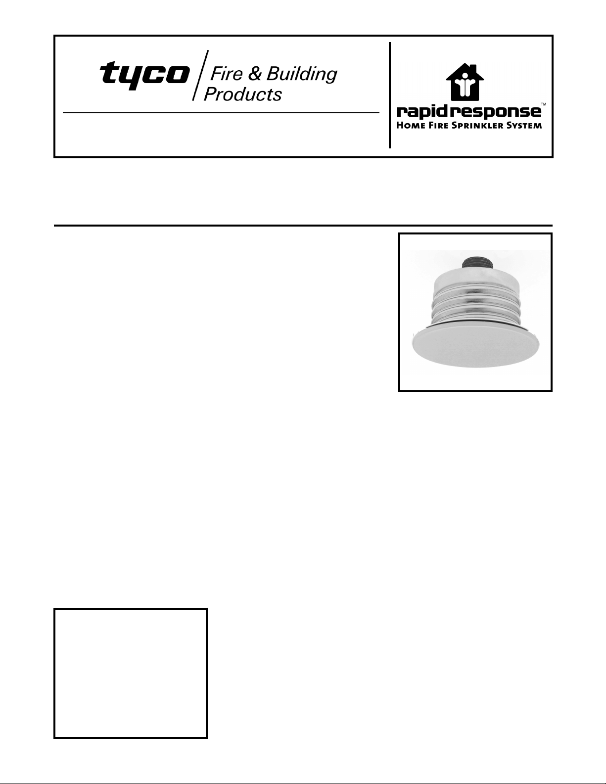
Series LFII Residential
Concealed Pendent Sprinklers, Flat Plate
4.2 K-factor
pressures, enabling smaller pipe sizes
General
Description
The Series LFII (TY2596) Residential
Concealed Pendent Sprinklers are
decorative, fast response, fusible solder sprinklers designed for use in residential occupancies such as homes,
apartments, dormitories, and hotels.
The cover plate a sse mbly conceals
the sprinkler opera ting co mponents
abovetheceiling.The flatprofile of the
cover plate provides the optimum aesthetically appealing sprinkler design.
In addition, the concealed design of
the Series LFII (TY2596) provides 1/2
inch (12,7 mm) vertical adjustment.
This adjustment reduces the accuracy
to which the fixed pipe drops to the
sprinklers must be cut to help assure
a perfect fit installation.
The Series LFII are to be used in wet
pipe residential sprinkler systems for
one- andtwo-family dwellings and mobile homes per NFPA 13D; wet pipe
residential sprinkler systems for residential occupancies up to and including four stories in height per NFPA
13R;or, wet pipe sprinkler systems for
the residential portions of any occupancy per NFPA 13.
The Series LFII (TY2596) has a 4.2
(60,5) K-factor that provides the requiredresidential flowratesat reduced
IMPORTANT
Always refer to Technical Data
Sheet TFP700 for the “INSTALLER
WARNING” that provides cautions
with respect to handling and installation ofsprinkler systems and components. Improper handling and installation can permanently damage
a sprinkler system or its components and cause the sprinkler to fail
tooperate in afire situationor cause
it to operate prematurely.
and water supply requirements.
The Series LFII (TY2596) has been
designed wi th heat sensiti vity and
water distribution characteristics
provento helpin thecontrol ofresidential fires and to improve the chance for
occupants to escape or be evacuated.
The Series LFII (TY2596) Residential
Concealed Pendent Sprinklers are
shipped with a Disposable Protective
Cap.The ProtectiveCap istemporarily
removed for installation, and then it
can be replaced to help protect the
sprinkler while the ceiling is being installed or finished. The tip of the Protective Cap can also be used to mark
the center of the ceiling hole into plaster board, ceiling tiles, etc. by gently
pushingthe ceiling productagainst the
Protective Cap. When the ceiling installation is complete the Protective
Cap is removed and the Cover Plate
Assembly installed.
WARNINGS
The Series LFII (TY2596) Residential
Concealed Pendent Sprinklers described herein must be installed and
maintained in complian ce with this
document, as well as with the applicable stand ar ds of the National Fir e Protection Association, in addition to the
standardsof any other authoritieshaving jurisdiction. Failure to do so may
impair the performance of these devices.
The owner is responsible for maintaining their fire protection system and devices in proper operating condition.
The installing contractor or sprinkler
manufacturer should be contacted
with any questions.
Sprinkler/Model
Identification
Number
SIN TY2596
Technical
Data
Approvals:
UL and C-UL Listed. NYC Approved
under MEA 44-03-E.
Maximum Working Pressure:
175 psi (12,1 bar)
Discharge Coefficient:
K=4.2GPM/psi
Temperature Rating:
160°F/71°C Sprinkler with
135°F/57°C Cover Plate
Vertical Adjustment:
1/2 inch (12,7 mm)
Finishes:
Cover Plate:
Flat White, Bright White, Chrome, or
Custom
Physical Characteristics:
Body ..............Brass
Cap . . . . . . . . . . . . . . Bronze
Saddle.............Brass
SealingAssembly..........
. . . . . Beryllium Nickel w/ Teflon†
Soldered Link Halves . . . . . Ni ck el
Lever . . . . . . . . . . . . . Bronze
Compression Screw . . . . . . Brass
Deflector........... Copper
1/2
(60,5 LPM/bar
1/2
)
Page 1 of 4 TFP440
JANUARY, 2006
Page 2
Page2of4
TFP440
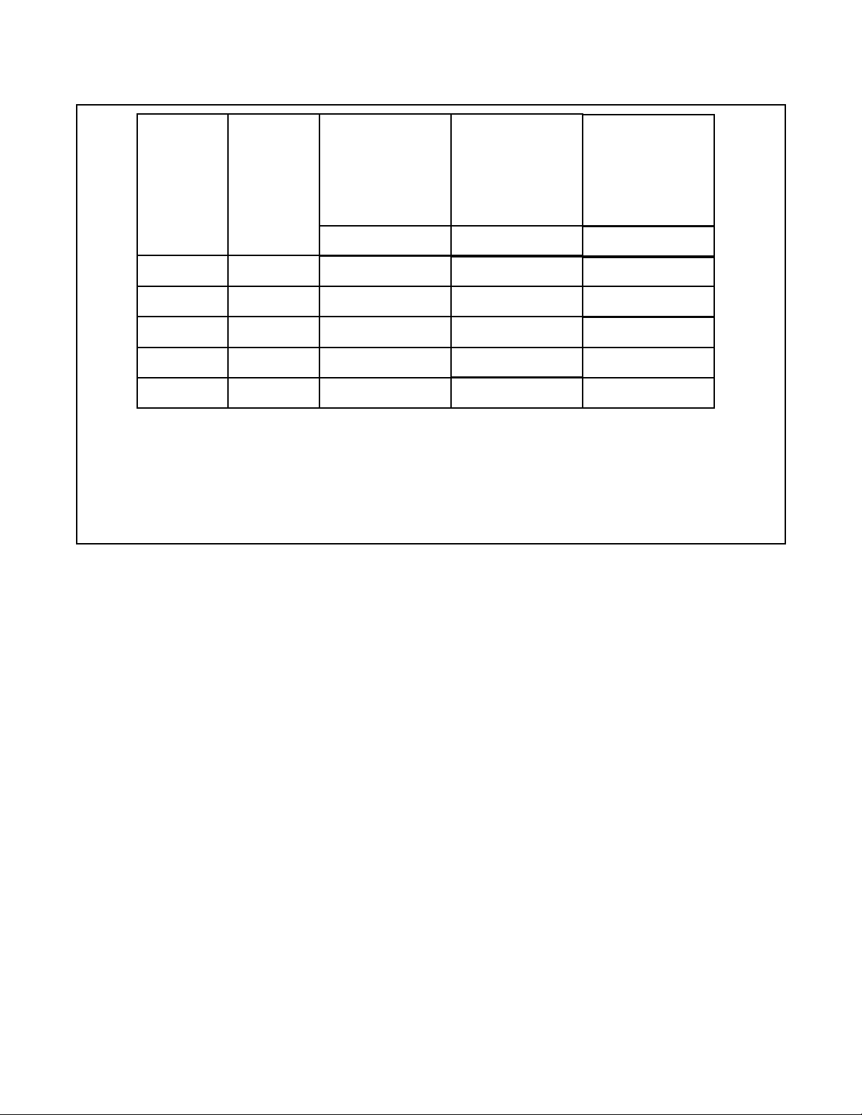
Minimum Flow
Maximum
Coverage
(a)
Area
Ft. x Ft.
(m x m)
12 x 12
(3,7 x 3,7)
14 x 14
(4,3 x 4,3)
16 x 16
(4,9 x 4,9)
18 x 18
(5,5 x 5,5)
20 x 20
(6,1 x 6,1)
(a) For coverage area dimensions less than or b etwee n those indicated, it is necessary to use the minimum required flow for the
next highest coverage area for which hydraulic design criteria are st ated.
(b) Requirement is based on minimum flow in GPM (LPM) from each sprinkler. The associated residua l pressures are calculated
using the nominal K-factor. Refer to Hy draulic Design Criteria Section for details.
Maximum
Spacing
Ft.
(m)
12
(3,7)
14
(4,3)
16
(4,9)
18
(5,5)
20
(6,1)
Residual Pressure
For Horizontal Ceiling
(Max. 2 Inch Rise
for 12 Inch Run)
160°F/71°C
Sprinkler
13 GPM (49,2 LPM)
9.6 psi (0,66 bar)
14 GPM (53,0 LPM)
11.1psi(0,77bar)
16 GPM (60,6 LPM)
14.5psi(1,00bar)
20 GPM (75,7 LPM)
22.7psi(1,57bar)
24 GPM (90,8 LPM)
32.7psi(2,25bar)
(b)
and
Minimum Flow
Residual Pressure
For Sloped Ceiling
(Greater Than 2 Inch
Rise Up To
Max. 4 Inch Rise
for 12 Inch Run)
160°F/71°C
Sprinkler
18 GPM (68,1 LPM)
18.4psi(1,27bar)
18 GPM (68,1 LPM)
18.4psi(1,27bar)
18 GPM (68,1 LPM)
18.4psi(1,27bar)
20 GPM (75,7 LPM)
22.7psi(1,57bar)
26 GPM (98,4 LPM)
38.3psi(2,64bar)
(b)
and
Minimum Flow
Residual Pressure
For Sloped Ceiling
(Greater Than 4 Inch
Rise Up To
Max. 8 Inch Rise
for 12 Inch Run)
160°F/71°C
Sprinkler
18 GPM (68,1 LPM)
18.4psi(1,27bar)
18 GPM (68,1 LPM)
18.4psi(1,27bar)
18 GPM (68,1 LPM)
18.4psi(1,27bar)
N/A
N/A
(b)
and
TABLE A
NFPA 13D AND NFPA 13R WET PIPE HYDRAULIC DESIGN CRITERIA
FOR THE SERIES LFII (TY2596) RESIDENTIAL CONCEALED PENDENT SPRINKLER
Guide Pin Housing . . . . . . Bronze
Guide Pins . . . . . . Stainless Steel
SupportCup .......... Steel
CoverPlate..........Copper
Retainer ............Brass
Cover Plate Ejection Spring . . . . .
............StainlessSteel
†DuPont Registered Trademark
Operation
When exposed to heat from a fire, the
Cover Pla te, w hic h i s no rma lly soldered to the Support Cup at three
points, falls away to expose the Sprinkler Assembly. At this pointthe Deflector supported by the Arms drops down
to its operated position. The fusible
link of the Sprinkler Assembly is comprised of two link halves that are soldered together with a thin layer of solder. When the ra ted temperature is
reached, the solder melts and the two
linkhalves separateallowing the sprinkler to activate and flow water.
Design
Criteria
The Series LFII (TY2596) Residential
Concealed Pendent Sprinklers are UL
and C-UL Listed for installation in accordance with the following cr iteria.
When conditions exist that are outside
NOTE
thescope of the providedcriteria, refer
to the Residen tial Sprinkler Design
Guide TFP490 for the manufacturer’s
recommendationsthat may be acceptable to the Authority Having Jurisdiction.
System Type. Only wet pipe systems
may be utilized.
Hydraulic Design. The minimum required sprinkler flow rate for systems
designed to NFPA 13D or NFPA 13R
are given in Table A as a function of
temperature rating and the maximum
allowable coverage areas. The sprinkler flow rate is the minimum required
discharge from each of the total
number of “design sprinklers” as
specified in NFPA 13D or NFPA 13R.
Forsystems designed to NFPA13, the
number of design sprinklers is to be
the four most hydraulically demanding
sprinklers. The minimum required dischargefrom each of thefour sprinklers
is to be the greater of the following:
• The flow rates given in Table A for
NFPA 13D and 13R as a function of
temperature rating and the maximum allowable coverage area.
• A minimum dischargeof 0.1gpm/sq.
ft. over the “design area” comprised
of the four most hydraulically demanding sprinklers for the actual
coverage areas being protected by
the four sprinklers.
Obstruction To Water Distribution.
Locations of sprinklers are to be in
accordance with the obstruction rules
of NFPA 13 for residential sprinklers.
Operational Sensitivity. The sprinklers are to be installed relative to the
ceiling mounting surface as shown in
Figure 3.
Sprinkler Spacing. The minimum
spacing between sprinklers is 8 feet
(2,4 m). The maximum spacing between sprinklers cannot exceed the
length of the coverage area (Ref. Table A) being hydraulically calculated
(e.g., maximum 12 feet for a 12 ft. x
12ft. coverage area, or 20 feet fora 20
ft. x 20 ft. coverage area).
Installation
The Series LFII (TY2596) must be installed in accordance with the following instructions:
NOTES
Damage to the fusible Link Assembly
during installation can be avoided by
handling the sprinkler by the frame
arms only (i.e., do not apply pressure
to the fusible link Assembly).
A leaktight 1/2 inchNPTsprinkler joint
should be obtained with a torque of 7
to 14 ft.lbs. (9,5 to 19,0 Nm). A maxi-
Page 3

TFP440
/
C
C
Page 3 of 4
BODY
(1/2" NPT)
CAP
SADDLE
SUPPORT
CUP WITH
ROLL FORMED
THREADS
GUIDE
PIN
GUIDE PIN
HOUSING
DEFLECTOR
THREAD INTO
SUPPORT CUP
UNTIL MOUNTING
SURFACE IS
FLUSH WITH
CEILING
SPRINKLER/SUPPORT CUP
ASSEMBLY
SEALING
ASSEMBLY
SPRINKLER
WRENCHING
AREA
COMPRESSION
SCREW
LEVER
SOLDER LINK
ELEMENT
DEFLECTOR
(OPERATED
POSITION)
RETAINER
WITH THREAD
DIMPLES
EJECTION
SPRING
mum of 21 ft.lbs. (28,5 Nm) of torque
is to be used to install sprinklers.
Higher levels of torque may distort the
sprinkler inlet with consequent leakage or impairment of the sprinkler.
Do not attempt to compensate for insufficientadjustment inan Escutcheon
Plate by under- or over-tightening the
Sprinkler. Readjust the position of the
sprinkler fitting to suit.
Step 1. The sprinkler must only be
installed in the pendent position and
with the centerline of the sprinkler perpendicular to the mounting surface.
Step 2 . Remove the Protective Cap.
Step 3. With pipe thread sealant ap-
plied to the pipe threads, and using
the W-Type 18 Wrench shown in Figure 2, install and tighten the Sprinkler/Support Cup Assembly into the fitting. The W-Type 18 Wrench will
accept a 1/2 inch ratchet drive.
H
WREN
RECESS
SOLDER
TAB
1/2"
NPT
COVER-
RETAINER
COVER PLATE/RETAINER
ASSEMBLY
COVER
PLATE
FIGURE 1
SERIES LFII (TY2596) RESIDENTIAL
CONCEALED PENDENT SPRINKLER
2-1
2" DIA.
(63,5 mm)
SPRINKLER-
SUPPORT CUP
ASSEMBLYASSEMBLY
3-3/16" DIA.
(81,0 mm)
1/2" (12,7 mm)
THREADED
ADJUSTMENT
1/8" GAP
(3,2 mm)
3/16"
(4,8 mm)
FACE OF
SPRINKLER
FITTING
1-15/16"±1/4"
(49,2 mm
±6,4 mm)
MOUNTING
SURFACE
TIP OPERATEDPOSITION
DISPOSABLE
PROTECTIVE CAP
SPRINKLER-
SUPPORT CUP
ASSEMBLY
OPERATED
SPRINKLER
COVER
PLATE
RETAINER
1/2" (12,7 mm)
1" (25,4 mm)
FIGURE 3
SERIES LFII (TY2596) RESIDENTIAL CONCEALED PENDENT SPRINKLER
INSTALLATION DIMENSIONS / PROTECTIVE CAP / ACTIVATED DEFLECTOR
PUSH WRENCH
IN TO ENSURE
ENGAGEMENT
WITH SPRINKLER
WREN
HINGAREA
FIGURE 2
W-TYPE 18
SPRINKLER WRENCH
DEFLECTOR IN
Page 4

Page4of4
TFP440
Step 4. Replace the ProtectiveCap by
pushing it upwards until it bottoms out
against the Support Cup. The Protective Cap helps prevent damage to the
Deflector and Arms during ceiling installation and/or during application of
the finish coating of the ceiling. It may
also be used to locate thecenter of the
clearance hole by gently pushing the
ceiling material against the center
point o f the Cap.
NOTE
As long as the protective Cap remains
in place, the system is considered to
be “Out Of Service”.
Step 5.After theceiling hasbeen completed with the 2-1/2 inch (63 mm)
diameter clearance hole and in preparation forinstalling the Cover Plate Assembly, remove and discard the Protective Cap, and verify that the
Deflector moves up and down freely.
Ifthe Sprinklerhas been damagedand
the Deflector does not move up and
down freely, replace the entire Sprinkler assembly. Do not attempt to modify or repair a damaged sprinkler.
Step 6. Screw on the Cover Plate Assembly until its flange comes in contact with the ceiling.
Do not continue to screw on the Cover
Plate Assembly such that it lifts a ceiling panel out of its normal position.
If the Cover Plate Assembly cannotbe
engaged with the Mounting Cup or the
Cover Plate Assembly cannot be engaged sufficiently to contact the ceiling, the Sprinkler Fitting must be repositioned.
Care and
Maintenance
The Serie s L FII (TY25 96) must be
maintained and serviced in accordance with the following instructions:
NOTES
Absence of an Escutcheon Plate may
delay the sprinkler operation in a fire
situation.
Before closing a fire protectionsystem
main control valve for maintenance
work on the fir e pro tection system
which it controls, permission to shut
down the affected fire protection system must be obtained from the proper
authorities and all personnel who may
be affected by this action must be notified.
Sprinklers which are found to be leaking or exhibiting visible signs of corrosion must be replaced.
Automatic sprink ler s must never be
painted, plated, coated, or otherwise
altered after leaving the factory. Modified or over heated sprinklers must be
replaced.
Care must be exercised to avoid damage - before, during, and after installation. Sprinkl er s d am a ged b y dr op ping, striking, wr ench twist/slippage,
or the like, must be replaced.
The owner is responsible for the inspection, testing, and maintenance of
their fire protection system and devices in comp lia nce with this document, as well as with the applicable
standards of the National Fire Protection Association (e.g., NFPA 25), in
addition to the standards of any other
authorities having jurisdiction. The installing contractor or sprinkler manufacturer should be contacted relative
to any questions.
NOTE
The owner must assure that the sprinklers are not used for hanging of any
objectsand that the sprinklersare only
cleaned by means of gently dusting
with a feather duster; otherwise, nonoperation in the event of a fire or inadvertent operation may result.
It is recommended that automatic
sprinkler systems be inspected,
tested, and maintained by a qualified
Inspection Service in accordance with
local requirements and/or national
codes.
Limited
Warranty
Products manufactured by Tyco Fire&
Building Products (TFBP) are warranted solely to the original Buyer for
ten (10) years against defects in material and workmanship when paid for
and properly installed and maintained
under normal use and service. This
warranty will expire ten (10) years
from date of shipment by TFBP. No
warranty is given for products or components manufactured by companies
not affiliated by ownership with TFBP
or for products and components which
havebeen subjectto misuse,improper
installation, corrosion, or which have
not been installed, maintained, modified or repaired in accordancewith applicable Standards of the National Fire
Protection Association, and/or the
standards of any other Authorities
Having Jurisdiction. Materials found
by TFBP to be defective shall beeither
repaired or replaced, at TFBP’s sole
option. TFBP neither assumes, nor
authorizesany personto assumefor it,
any other obligationin connection with
the sale of products or parts of prod-
ucts.TFBP shall not be responsiblefor
sprinkler systemdesign errors or inaccurate or incomplete information supplied by Buyer or Buy er’s representatives.
In no event shall TFBP be liable, in
contract, tort, strict liability or under
any other legal theory, for incidental,
indirect,special or consequentialdamages, including but not limited to labor
charges, regardless of whether TFBP
was informed about the possibility of
such damages, and in no event shall
TFBP’s liability exceed an amount
equal to the sales price.
The foregoing wa rr an ty is made in lieu
of any and all other warranties, express or implied, including warranties
of merchantability and fitness for a
particular purpose.
This limited warranty sets forth the exclusive remedy for claims based on
failure of or defect in products, materials or components, whether the claim
is made in contract, tort, strict liability
or any other legal theory.
This warranty will apply to the full extent permitted by law. The invalidity, in
whole or part, of any portion of this
warranty will not affect the remainder.
Ordering
Procedure
When placing an order, indicate the
full product name. Contact your local
distributor for availability..
Sprinkler Assembly:
SeriesLFII (TY2596), K=4.2,ResidentialConcealed Pendent Sprinkler without Cover Plate Assembly,
P/N 51-122-1-160.
Cover Plate Assembly:
Cover Plate Assembly having a (specify) finish for the Series LFII (TY2596),
K=4.2, Re sidential Concealed Pendent Sprinkler, P/N (specify).
Chrome . . . . . . . . . . . . . . . . . . P/N 56- 122-9-135
Off White . . . . . . . . . . . . . . . . . P/N 56-122-0-135
Bright White. . . . . . . . . . . . . . . P/N 56-122-4-135
Flat White . . . . . . . . . . . . . . . . P/N 56-122-5-135
White (RAL9010)* . . . . . . . . . . P/N 56-122-3-135
Custom . . . . . . . . . . . . . . . . . . P/N 56-122-X-135
*Eastern Hemisphere sales only.
Sprinkler Wr ench:
Specify: W-Type18 Sprinkler Wrench,
P/N 56-000-1-265.
TYCO FIRE & BUILDING PRODUCTS, 451 North Cannon Avenue, Lansdale, Pennsylvania 19446
 Loading...