

Page 1
800-381-9312
Technical Services
+1- 40 1-7 81- 822 0
www.tyco-fi re.com
RAPID RESPONSE Series LFII Residential Sprinklers
4.9 K-factor Flat-Plate Concealed Pendent
Wet Pipe and Dry Pipe Systems
General
Description
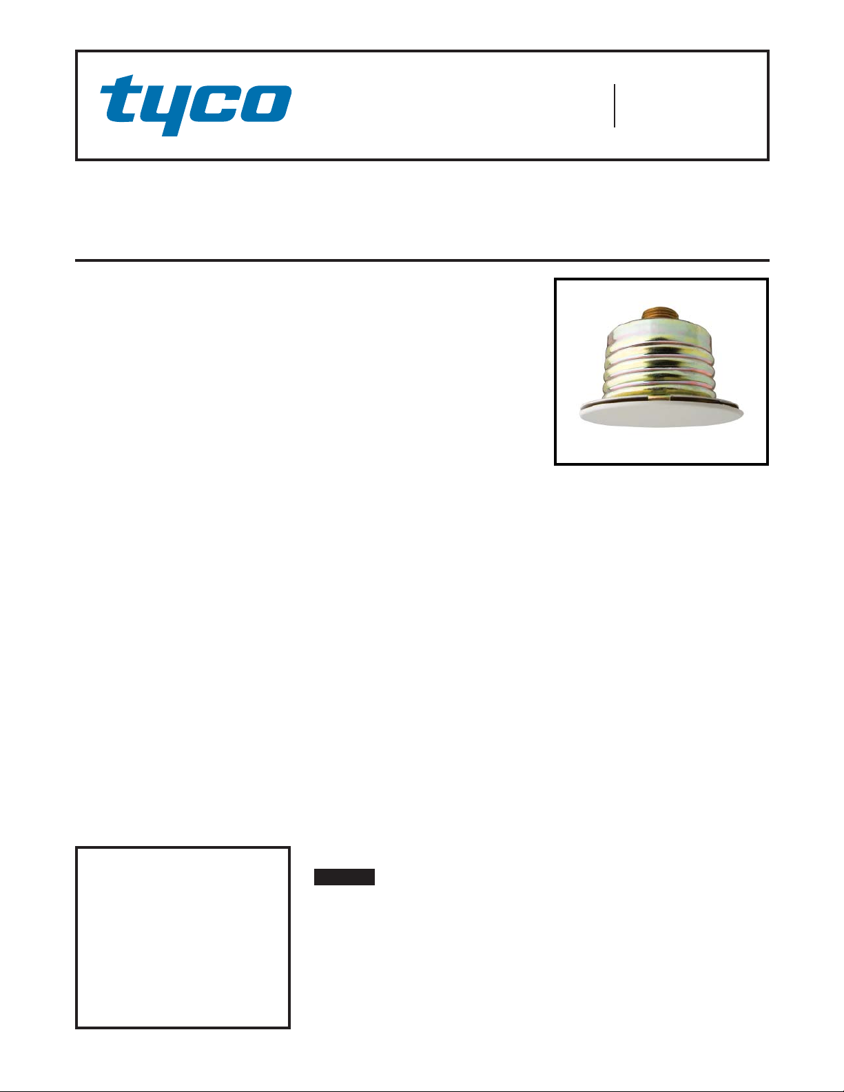
The TYCO RAPID RESPONSE Series
LFII Residential Flat-Plate Concealed
Pendent Sprinklers (TY2524) are decorative, fast response, fusible solder sprinklers designed for use in residential occupancies such as homes, apartments,
dormitories, and hotels.
The Cover Plate/Retainer Assembly conceals the sprinkler operating components above the ceiling. The at pro le
of the Cover Plate provides the optimum
aesthetically appealing sprinkler design.
Additionally, the concealed design of the
Series LFII Residential Flat-Plate Concealed Pendent Sprinklers provides 1/2
inch (12,8 mm) vertical adjustment. This
adjustment provides a measure of exibility when cutting xed sprinkler drops.
The Series LFII Residential Flat-Plate
Concealed Pendent Sprinklers are intended for use in the following systems:
• wet and dry pipe residential sprinkler systems for one- and two-family dwellings and mobile homes per
NFPA 13D
• wet and dry pipe residential sprinkler systems for residential occupancies up to and including four stories in height per NFPA 13R
• wet and dry pipe sprinkler systems
for the residential portions of any
occupancy per NFPA 13.
The Series LFII Residential Sprinklers
have been designed with heat sensitivity and water distribution characteristics
proven to help in the control of residen-
IMPORTANT
Always refer to Technical Data
Sheet TFP700 for the “INSTALLER
WARNING” that provides cautions
with respect to handling and installation of sprinkler systems and components. Improper handling and installation can permanently damage
a sprinkler system or its components
and cause the sprinkler to fail to
operate in a fi re situation or cause it
to operate prematurely.
tial res and to improve the chance for
occupants to escape or be evacuated.
The Series LFII Residential Flat-Plate
Concealed Pendent Sprinklers are
shipped with a Disposable Protective
Cap. The Protective Cap protects the
sprinkler during ceiling installation or
nish. After ceiling installation is complete, the Protective Cap is removed
and the Cover Plate/Retainer Assembly is installed. Removing the Protective Cap is required for proper sprinkler
performance.
Dry Pipe System Application
The Series LFII Residential Flat-Plate
Concealed Pendent Sprinkler offers a
laboratory approved option for designing dry pipe residential sprinkler systems, whereas, most residential sprinklers are laboratory approved for wet
systems only.
Through extensive testing and as referenced in U.S. Patent 7,712,543, it has
been determined that the number of design sprinklers (hydraulic design area)
for the Series LFII Residential Flat-Plate
Concealed Sprinklers (TY2524) need not
be increased over the number of design
sprinklers (hydraulic design area) speci ed for wet pipe sprinkler systems, as
is customary for density/area sprinkler
systems designed per NFPA 13, 13D,
or 13R.
Consequently, the Series LFII Residential Flat-Plate Concealed Sprinklers
(TY2524) offer the features of non-water lled pipe in addition to not having to
increase the number of design sprinklers
(hydraulic design area) for systems designed to NFPA 13, 13D, or 13R. Nonwater lled pipe will permit options for
areas sensitive to freezing.
NOTICE
The Series LFII Residential Flat-Plate
Concealed Pendent Sprinklers (TY2524)
described herein must be installed and
maintained in compliance with this document and the applicable standards of
the National Fire Protection Association,
in addition to the standards of any authorities having jurisdiction. Failure to
do so may impair the performance of
these devices.
The owner is responsible for maintaining their fi re protection system and devices in proper operating condition. The
installing contractor or sprinkler manufacturer should be contacted with any
questions.
Sprinkler
Identifi cation
Number (SIN)
TY2524
Page 1 of 6 APRIL 2012 TFP443
Page 2
TFP443
Page 2 of 6
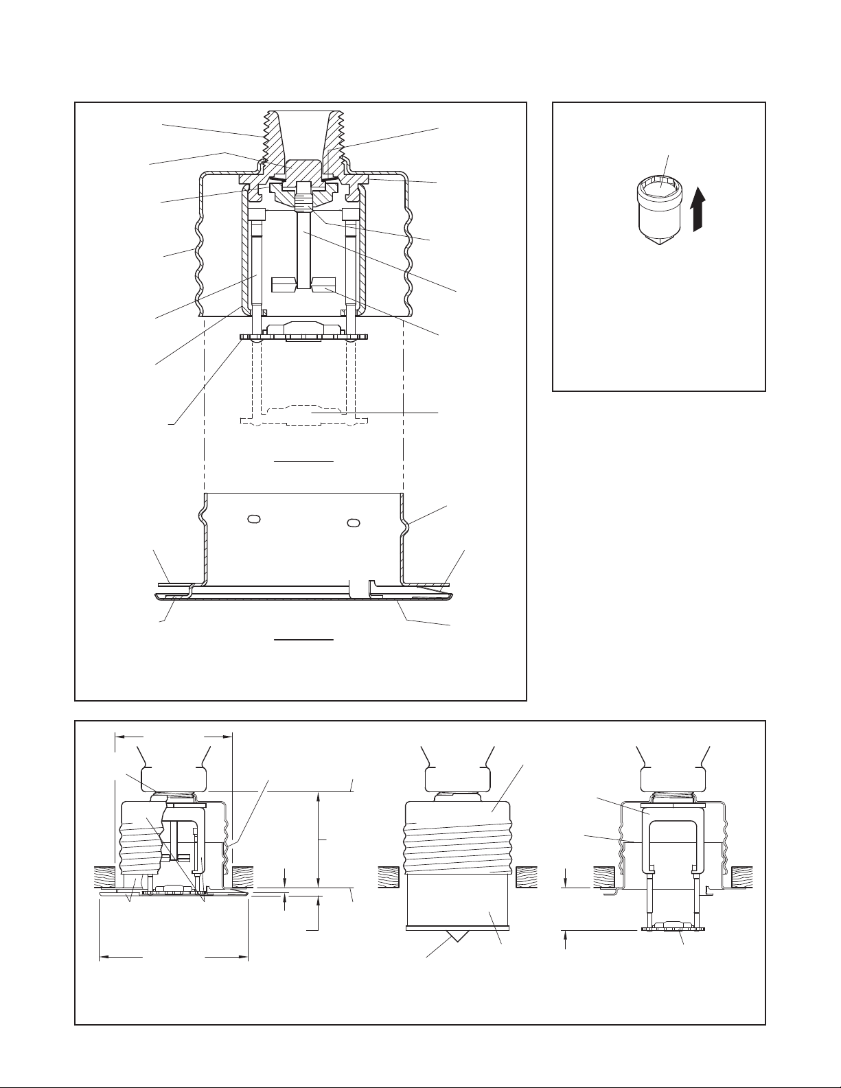
BODY
(1/2" NPT)
CAP
SADDLE
SUPPORT
CUP WITH
ROLL FORMED
THREADS
GUIDE
PIN
GUIDE PIN
HOUSING
DEFLECTOR
THREAD INTO
SUPPORT CUP
UNTIL MOUNTING
SURFACE IS
FLUSH WITH
CEILING
SPRINKLER/SUPPORT CUP
ASSEMBLY
SEALING
ASSEMBLY
SPRINKLER
WRENCHING
AREA
COMPRESSION
SCREW
LEVER
SOLDER LINK
ELEMENT
DEFLECTOR
(OPERATED
POSITION)
RETAINER
WITH THREAD
DIMPLES
EJECTION
SPRING
WRENCH
RECESS
PUSH WRENCH
IN TO ENSURE
ENGAGEMENT
WITH SPRINKLER
WRENCHING AREA
FIGURE 2
W-TYPE 18
— SPRINKLER WRENCH —
SOLDER
TAB
COVER PLATE/RETAINER
ASSEMBLY
COVER
PLATE
FIGURE 1
RAPID RESPONSE SERIES LFII RESIDENTIAL FLAT-PLATE CONCEALED
PENDENT SPRINKLER (TY2524)
— ASSEMBLY —
SPRINKLER-
SUPPORT CUP
ASSEMBLY
DISPOSABLE
1/2"
NPT
COVER-
RETAINER
2-1/2" DIA.
(63,5 mm)
SPRINKLER-
SUPPORT CUP
ASSEMBLYASSEMBLY
3-3/16" DIA.
(81,0 mm)
1/2" (12,7 mm)
THREADED
ADJUSTMENT
1/8" GAP
(3,2 mm)
3/16"
(4,8 mm)
FACE OF
SPRINKLER
FITTING
1-7/8"±1/8"
(47,6 mm
±3,2 mm)
MOUNTING
SURFACE
TIP OPERATED POSITION
PROTECTIVE CAP
FIGURE 3
PROTECTIVE CAP AND ACTIVATED DEFLECTOR
— INSTALLATION DIMENSIONS —
OPERATED
SPRINKLER
COVER
PLATE
RETAINER
7/8" (22,2 mm)
1-1/8" (28,6 mm)
DEFLECTOR IN
Page 3

TFP443
Page 3 of 6
Technical
Data
Approvals
UL and C-UL Listed
The TYCO RAPID RESPONSE Series
LFII Residential Flat-Plate Concealed
Pendent Sprinklers are only listed with
the Series LFII Concealed Cover Plates
having a factory-applied nish.
For details on approvals, refer to the Design Criteria section.
Maximum Working Pressure
175 psi (12,1 bar)
Discharge Coeffi cient
K=4.9 GPM/psi
Temp erat ure Rati ng
Sprinkler: 160°F (71°C)
Cover Plate: 139°F (59°C)
Vertical Adjustment
1/2 inch (12,7 mm)
Finishes
Refer to the Ordering Procedure section.
Physical Characteristics
Cover Plate/Retainer Assembly:
Cover Plate . . . . . . . . . . . . . Copper
Ejection Spring . . . . Stainless Steel
Retainer . . . . . . . . . . . . . . . . Brass
Sprinkler/Support Cup Assembly:
Body . . . . . . . . . . . . . . . . . . . Brass
Cap . . . . . . . . . . . . . . . . . . . Bronze
Saddle . . . . . . . . . . . . . . . . . . Brass
Sealing Assembly . . . . . . .Beryllium
Soldered Link Halves . . . . . . Nickel
Lever . . . . . . . . . . . . . . . . . . Bronze
Compression Screw . . . . . . . Brass
De ector . . . . . . . . . . . . . . . Bronze
Guide Pin Housing. . . . . . . . Bronze
Guide Pins . . . . . . . . . . . . . Bronze
Support Cup . . . . . . . . . . . . . . Steel
1/2
(70,6 LPM/bar
Nickel w/ TEFLON
1/2
)
Operation
When exposed to heat from a re, the
Cover Plate, which is normally soldered
to the Retainer at three points, falls away
to expose the Sprinkler/Support Cup Assembly. At this point, the De ector, supported by the Guide Pins, drops down
to its operated position.
The Solder Link Element of the Sprinkler/
Support Cup Assembly is comprised of
two link halves that are soldered together with a thin layer of solder. When the
rated temperature is reached, the solder melts and the two link halves separate, allowing the sprinkler to activate
and ow water.
Design
Criteria
The TYCO RAPID RESPONSE Series
LFII Residential Flat-Plate Concealed
Pendent Sprinklers (TY2524) are UL
and C-UL Listed for installation in accordance with this section:
Residential Sprinkler Design Guide
When conditions exist that are outside
the scope of the provided criteria, refer to the Residential Sprinkler Design
Guide TFP490 for the manufacturer's
recommendations that may be acceptable to the authority having jurisdiction.
System Type
Per the UL Listing, wet pipe and dry pipe
systems may be utilized. Per the C-UL
Listing, only wet pipe systems may be
utilized.
Refer to Technical Data Sheet TFP485
about the use of Residential Sprinklers
in residential dry pipe systems.
Hydraulic Design
(NFPA 13D and 13R)
For systems designed to NFPA 13D or
NFPA 13R, the minimum required sprinkler ow rate are given in Tables A and
B as a function of temperature rating
and the maximum allowable coverage
areas. The sprinkler ow rate is the minimum required discharge from each of
the total number of “design sprinklers”
as speci ed in NFPA 13D or NFPA 13R.
The number of “design sprinklers” speci ed in NFPA 13D and 13R for wet pipe
systems is to be applied when designing
dry pipe systems.
Hydraulic Design
(NFPA 13)
For systems designed to NFPA 13, the
number of design sprinklers is to be
the four most hydraulically demanding
sprinklers. The minimum required discharge from each of the four sprinklers
is to be the greater of the following:
• The ow rates given in Tables A and
B as a function of temperature rating
and the maximum allowable coverage area.
• A minimum discharge of 0.1 gpm/ft2.
over the “design area” comprised of
the four most hydraulically demanding sprinklers for the actual coverage
areas being protected by the four
sprinklers.
The number of “design sprinklers”
speci ed in NFPA 13 for wet pipe systems is to be applied when designing
dry pipe systems.
Dry Pipe System Water Delivery
When using the Series LFII Residential
Flat-Plate Concealed Pendent Sprinklers
(TY2524) in dry pipe sprinkler systems,
the time for water delivery exceed 15
seconds for the most remote operating sprinkler.
Obstruction to Water Distribution.
Sprinklers are to be located in accordance with the obstruction rules of
NFPA 13D, 13R, an d 13 as ap pl ic able
for residential sprinklers as well as with
the obstruction criteria described within
the Technical Data Sheet TFP490.
Operational Sensitivity
Install sprinklers relative to the ceiling
mounting surface as shown in Figure 3.
The Series LFII Residential Flat-Plate
Concealed Pendent Sprinklers must
not be used in applications where the
air pressure above the ceiling is greater
than that below. Down drafts through
the Support Cup can delay sprinkler operation in a re situation.
Sprinkler Spacing
The minimum spacing between sprinklers is 8 feet (2,4 m). The maximum
spacing between sprinklers cannot exceed the length of the coverage area
(Table A) being hydraulically calculated
(e.g., a maximum of 12 feet for a 12 ft. x
12 ft. coverage area or 20 feet for a 20
ft. x 20 ft. coverage area.)
Page 4

TFP443
Page 4 of 6
(c, d, e)
(b)
Sloped Ceiling
(c, d, e)
(Greater than 4 inch rise
up to maximum 8 inch
rise for 12 inch run)
160°F (71°C)
Sprinkler
17 GPM (64,3 LPM)
12.0 psi (0,83 bar)
17 GPM (64,3 LPM)
12.0 psi (0,83 bar)
17 GPM (64,3 LPM)
12.0 psi (0,83 bar)
22 GPM (83,3 LPM)
20.2 psi (1,39 bar)
24 GPM (90,8 LPM)
24.0 psi (1,65 bar)
Minimum Flow and Residual Pressure
Maximum
Coverage
(a)
Area
Ft. x Ft .
(m x m)
Maximum
Spacing
Ft.
(m)
Horizontal Ceiling
(Maximum 2 inch rise
for 12 inch run)
(c, d, e)
160°F (71°C)
Sprinkler
12 x 12
(3,7 x 3,7)
14 x 14
(4,3 x 4,3)
16 x 16
(4,9 x 4,9)
18 x 18
(5,5 x 5,5)
20 x 20
(6,1 x 6,1)
(a) For coverage area dimensions less than or between those indicated, use the minimum required ow for the next highest coverage area for which
Hydraulic Design section under the Design Criteria are stated.
(b) The Minimum Flow requirement is based on minimum ow in GPM (LPM) from each sprinkler. The associated residual pressures are calculated using
the nominal K-factor. Refer to “Hydraulic Design” in the Design Criteria section for details.
(c) For NFPA 13D 2010 applications, Horizontal Ceiling criteria shall be used for certain sloped ceiling con gurations up to 8:12 pitch.
Refer to TIA 1028R for allowed sloped ceiling limitations when using horizontal ceiling criteria.
(d) For NFPA 13R applications, Horizontal Ceiling criteria may be used for sloped ceiling con gurations up to 8:12 pitch when acceptable to
the local authority having jurisdiction.
(e) For NFPA 13 residential applications, the greater of 0.1 gpm/ft.
this table must be used.
12
(3,7)
14
(4,3)
16
(4,9)
18
(5,5)
20
(6,1)
13 GPM (49,2 LPM)
7.0 psi (0,48 bar)
13 GPM (49,2 LPM)
7.0 psi (0,48 bar)
13 GPM (49,2 LPM)
7.0 psi (0,48 bar)
17 GPM (64,3 LPM)
12.0 psi (0,83 bar)
20 GPM (75,7 LPM)
16.7 psi (1,15 bar)
2
over the design area or the ow in accordance with the criteria in
WET PIPE SYSTEM
Sloped Ceiling
(Greater than 2 inch rise
up to maximum 4 inch
rise for 12 inch run)
160°F (71°C)
Sprinkler
17 GPM (64,3 LPM)
12.0 psi (0,83 bar)
17 GPM (64,3 LPM)
12.0 psi (0,83 bar)
17 GPM (64,3 LPM)
12.0 psi (0,83 bar)
22 GPM (83,3 LPM)
20.2 psi (1,39 bar)
24 GPM (90,8 LPM)
24.0 psi (1,65 bar)
SERIES LFII RESIDENTIAL FL AT-PLATE CONCEALED PENDENT SPRINKLER (TY2524)
TABLE A
NFPA 13D, 13R, AND 13 HYDRAULIC DESIGN CRITERIA
— WET PIPE SYSTEMS —
Maximum
Coverage Area
Ft. x Ft .
(m x m)
(a)
Maximum Spacing
Ft.
Horizontal Ceiling Minimum Flow and Residual Pressure
(m)
Minimum Flow and Residual Pressure
(Maximum 2 Inch Rise for 12 Inch Run)
160°F (71°C) Sprinkler
DRY PIPE SYSTEM
12 x 12
(3,7 x 3,7)
14 x 14
(4,3 x 4,3)
16 x 16
(4,9 x 4,9)
18 x 18
(5,5 x 5,5)
20 x 20
(6,1 x 6,1)
(a) For coverage area dimensions less than or between those indicated, use the minimum required ow for the next highest
coverage area for which Hydraulic Design section under the Design Criteria are stated.
(b) The Minimum Flow requirement is based on minimum ow in GPM (LPM) from each sprinkler. The associated residual pressures
are calculated using the nominal K-factor. Refer to “Hydraulic Design” in the Design Criteria section for details.
(c) For NFPA 13 residential applications, the greater of 0.1 gpm/ft.
this table must be used.
12
(3,7)
14
(4,3)
16
(4,9)
18
(5,5)
20
(6,1)
15 GPM (56,8 LPM)
9.4 psi (0,65 bar)
15 GPM (56,8 LPM)
9.4 psi (0,65 bar)
16 GPM (60,6 LPM)
10,7 psi (0,74 bar)
17 GPM (64,3 LPM)
12.0 psi (0,83 bar)
21 GPM (79,5 LPM)
18,4 psi (1,27 bar)
2
over the design area or the ow in accordance with the criteria in
(b)
(c)
SERIES LFII RESIDENTIAL FL AT-PLATE CONCEALED PENDENT SPRINKLER (TY2524)
TABLE B
NFPA 13D, 13R, AND 13 HYDRAULIC DESIGN CRITERIA
— DRY PIPE SYSTEMS —
Page 5

TFP443
Page 5 of 6
Installation
The TYCO RAPID RESPONSE Series
LFII Residential Flat-Plate Concealed
Pendent Sprinklers must be installed in
accordance with this section:
General Instructions
Damage to the Solder Link Element during installation can be avoided by handling the sprinkler by the Support Cup
only; that is, do not apply pressure to the
Solder Link Element (Figure 1).
A leak-tight 1/2 inch NPT sprinkler joint
should be obtained by applying a minimum-to-maximum torque of 7 to 14
ft.-lbs. (9,5 to 19,0 Nm). Higher levels
of torque can distort the sprinkler inlet
with consequent leakage or impairment
of the sprinkler.
Do not attempt to compensate for insuf cient adjustment in the Cover Plate/
Retainer Assembly by under- or overtightening the sprinkler. Re-adjust the
position of the sprinkler tting to suit.
Step 1. Install pendent sprinklers in
the pendent position, with the centerline of the sprinkler perpendicular to the
mounting surface.
Step 2. Remove the Protective Cap.
Step 3. With pipe-thread sealant ap-
plied to the pipe threads, and using the
W-Type 18 Wrench shown in Figure 2,
install and tighten the Sprinkler/Support Cup Assembly into the tting. The
W-Type 18 Wrench accepts a 1/2 inch
ratchet drive.
Step 4. Replace the Protective Cap by
pushing it upwards until it bottoms out
against the Support Cup. The Protective Cap helps prevent damage to the
De ector and Guide Pins during ceiling
installation and/or during application of
the nish coating of the ceiling.
NOTICE
As long as the protective Cap remains
in place, the system is considered “Out
Of Service”.
Step 5. After the ceiling has been completed with the 2-1/2 inch (63 mm) diameter hole and in preparation for installing the Cover Plate/Retainer Assembly,
remove and discard the Protective Cap,
and verify that the De ector moves up
and down freely.
If the sprinkler has been damaged and
the de ector does not move up and
down freely, replace the entire sprinkler
assembly. Do not attempt to modify or
repair a damaged sprinkler.
Step 6. Screw on the Cover Plate/Retainer Assembly until its ange contacts
the ceiling. Do not continue to screw
on the Cover Plate/Retainer Assembly
such that it lifts a ceiling panel out of
its normal position.
If the Cover Plate/Retainer Assembly
cannot be engaged with the Mounting
Cup or the Cover Plate/Retainer Assembly cannot be engaged suf ciently to
contact the ceiling, the Sprinkler Fitting
must be repositioned.
Care and
Maintenance
The TYCO RAPID RESPONSE Series
LFII Residential Flat-Plate Concealed
Pendent Sprinkler (TY2524) must be
maintained and serviced in accordance
with ths section:
Before closing a re protection system
main control valve for maintenance work
on the re protection system that it controls, obtain permission to shut down the
affected re protection system from the
proper authorities and notify all personnel who may be affected by this action.
Absence of a Cover Plate may delay the
sprinkler operation in a re situation.
The owner must assure that the sprinklers are not used for hanging any objects and that the sprinklers are only
cleaned by means of gently dusting with
a feather duster; otherwise, non-operation in the event of a re or inadvertent
operation may result.
When properly installed, there is a nominal 1/8 inch (3,2 mm) air gap between
the lip of the Cover Plate and the ceiling, as shown in Figure 3. This air gap
is necessary for proper operation of the
sprinkler by allowing heat ow from a
re to pass below and above the Cover
Plate to help assure appropriate release
of the Cover Plate in a re situation. If the
ceiling needs repainting after sprinkler
installation, exercise care to ensure that
the new paint does not seal off any of
the air gap. Failure to do so may impair
sprinkler operation.
Factory painted Cover Plates must not
be repainted. They should be replaced,
if necessary, by factory painted units.
Non-factory applied paint may adversely
delay or prevent sprinkler operation in
the event of a re.
Do not pull the Cover Plate relative to the
Retainer. Separation may result.
Sprinklers which are found to be leaking
or exhibiting visible signs of corrosion
must be replaced.
Automatic sprinklers must never be
painted, plated, coated, or otherwise
altered after leaving the factory. Modi ed or overheated sprinklers must be
replaced.
Care must be exercised to avoid damage to the sprinklers - before, during,
and after installation. Sprinklers damaged by dropping, striking, wrench twist/
slippage, or the like, must be replaced.
The owner is responsible for the inspection, testing, and maintenance of
their re protection system and devices
in compliance with this document, as
well as with the applicable standards of
the National Fire Protection Association
(e.g., NFPA 25), in addition to the standards of any other authorities having jurisdiction. Contact the installing contractor or sprinkler manufacturer regarding
any questions.
Automatic sprinkler systems are recommended to be inspected, tested,
and maintained by a quali ed Inspection Service in accordance with local
requirements and/or national codes
.
Page 6

TFP443
Page 6 of 6
Limited
Warranty
Products manufactured by Tyco Fire
Production Products (TFPP) are warranted solely to the original Buyer for
ten (10) years against defects in material and workmanship when paid for
and properly installed and maintained
under normal use and service. This
warranty will expire ten (10) years from
date of shipment by TFPP. No warranty is given for products or components
manufactured by companies not af liated by ownership with TFPP or for
products and components which have
been subject to misuse, improper installation, corrosion, or which have not
been installed, maintained, modi ed or
repaired in accordance with applicable
Standards of the National Fire Protection Association, and/or the standards of
any other authorities having jurisdiction.
Materials found by TFPP to be defective shall be either repaired or replaced,
at TFPP’s sole option. TFPP neither assumes, nor authorizes any person to
assume for it, any other obligation in
connection with the sale of products
or parts of products. TFPP shall not be
responsible for sprinkler system design
errors or inaccurate or incomplete information supplied by Buyer or Buyer’s
representatives.
In no event shall TFPP be liable, in contract, tort, strict liability or under any
other legal theory, for incidental, indirect, special or consequential damages,
including but not limited to labor charges, regardless of whether TFPP was informed about the possibility of such
damages, and in no event shall TFPP’s
liability exceed an amount equal to the
sales price.
The foregoing warranty is made in lieu
of any and all other warranties, express
or implied, including warranties of merchantability and tness for a particular
purpose.
This limited warranty sets forth the exclusive remedy for claims based on failure of or defect in products, materials or
components, whether the claim is made
in contract, tort, strict liability or any other legal theory.
This warranty will apply to the full extent
permitted by law. The invalidity, in whole
or part, of any portion of this warranty
will not affect the remainder.
Ordering
Procedure
Contact your local distributor for availability. When placing an order, indicate
the full product description and Part
Number (P/N).
Sprinkler/Support Cup Assembly
Specify: Series LFII (TY2524), K=4.9
(70,6), Residential Flat-Plate Concealed
Pendent Sprinkler without Cover Plate/
Ret ain er A s semb ly, P/N 51-114 -1-160 .
Cover Plate/Retainer Assembly for
Horizontal or Sloped Ceiling
Applications
Specify: Series LFII (TY2524), K=4.9
(70,6), Residential Flat-Plate Concealed
Pendent Sprinkler Cover Plate/Retainer Assembly with (specify) nish, P/N
(specify):
Off White . . . . . . . . . . . . . . . . P/N 56-201-0-135
Pure White*
(RAL9010) . . . . . . . . . . . . . . P/N 56-201-3-135
Signal White**
(RAL9003) . . . . . . . . . . . . . . P/N 56-201-4-135
Standard White (Grey White)
(RAL9002) . . . . . . . . . . . . . . P/N 56-201-5-135
Custom . . . . . . . . . . . . . . . . . . .P/N 56-201-X-135
* Eastern Hemisphere sales only
** Previously known as Bright White
Note: All Custom Cover Plates are painted using Sherwin Williams Interior Latex Paint. Contact
TYCO Customer Ser vice with any questions related
to custom orders.
Optional Cover Plate/Retainer Assembly for Horizontal Ceiling
Applications Only
Specify: Series LFII (TY2524), K=4.9
(70,6), Residential Flat-Plate Concealed
Pendent Sprinkler Cover Plate/Retainer Assembly with (specify) nish, P/N
(specify):
Off White . . . . . . . . . . . . . . . . .P/N 56-122-0-135
Pure White*
(RAL9010) . . . . . . . . . . . . . . . . P/N 56-122-3-135
Signal White**
(RAL9003) . . . . . . . . . . . . . . . . P/N 56-122-4-135
Custom . . . . . . . . . . . . . . . . . . . P/N 56-122-X-135
* Eastern Hemisphere sales only
** Previously known as Bright White
Note: All Custom Cover Plates are painted using Sherwin Williams Interior Latex Paint. Contact
TYCO Customer Ser vice with any questions related
to custom orders.
Sprinkler Wrench
Specify: W-Type 18 Sprinkler Wrench,
P/N 56-000-1-265.
Copyright © 2012 Tyco Fire Protection Products. All rights reserved.
TEFLON is trademark of The DuPont Corporation.
 Loading...