

Page 1

intrusion
PowerSeries Pro
HS3032 / HS3128 / HS3248 USER MANUAL
WARNING: This manual contains information on limitations regarding product use and function and
information on the limitations as to liability of the manufacturer. The entire manual should be carefully read.
Page 2

Chapter 2
1.0 Quick Reference 5
2.0 Safety Inst ructions 7
3.0 The PowerSeries Pro Security System 8
3.1 General System Operation 8
3.2 Carbon Monoxide Detection 8
3.3 Fire Detection 8
3.4 Testing the System 8
3.5 Performing a Keypad and Siren test 9
3.6 Monitoring 9
3.7 Maintenance 9
3.8 Applicable models 9
4.0 Securing the Premises 10
4.1 Arming the System 10
4.1.1 Away Arming the System with the Keypad 10
4.1.1.1 Arming the system in Away mode 10
4.1.1.2 Canceling the arming sequence 11
4.1.2 Arming the system in Stay mode 11
4.1.3 Canceling the arming sequence 11
4.1.3.1 Silent Exit Delay 11
4.2 Arming the System with a 2-Way Wireless Key 12
4.3 Arming the System with a Proximity Tag 12
4.4 Night Arming 12
4.4.1 Arming the system in Night mode 12
4.4.2 Disarming a system that is in Night mode 12
4.5 No-entry arming 12
4.5.1 Arming the system using the No-entr y arming feature 13
4.5.2 Canceling the arming sequence 13
4.6 Exit Delay Time Restart 13
4.7 The Quick Exit feature 13
4.7.1 Exiting the premises using the Quick Exit feature 13
4.8 Bypassing Zones 13
4.8.1 Additional Bypass Features 14
4.8.1.1 Bypassing individual zones 14
4.8.1.2 Bypassing all open zones 14
4.8.1.3 Recalling the last bypassed zones 15
4.8.1.4 Clearing the Bypass Indication from all zones 15
4.9 Bypass Groups 15
4.9.1 Programming a Bypass group 15
4.9.2 Loading a Bypass group 15
4.10 Arming Tr oubles and Exit F aults 16
4.10.1 Arming Troubles 16
4.10.2 Correcting an Arming error 16
4.10.3 Audible Exit Faults 16
4.10.4 To Correct an Exit Fault 16
4.11 Disarming the System 16
4.12 Disarming the system with a keypad 16
4.13 Disarming the system with a 2-way Wir eless Key 16
4.14 Disarming the system with a proximity tag 17
4.14.1 Disar ming error 17
5.0 Alarms 18
5.1 Emergency Keys 18
5.2 Fire alarm 18
5.2.1 Silencing a fire alarm 18
5.2.2 Bells Silenced LCD display for fire alarms 18
5.3 Resetting Smoke Detectors 19
5.4 Carbon Monoxide Alarm - 4 beeps, long pause, 4 beeps 19
5.4.1 Bells Silenced LCD display for CO alarms 19
5.5 Intrusion (Burglary) Alarm - Continuous Siren 19
5.6 Alarm Cancel Window 19
5.7 Viewing Alarms in Memory 20
5.7.1 Alarm Messages 20
- 2 -
Page 3

Chapter 2
6.0 Wireless Keys 21
6.1 Using 2-way Wireless Keys 21
6.2 Using Proximity Tags 21
7.0 Managing Users 22
7.1 Access Code T ypes 22
7.2 Opening the Access Codes menu 23
7.3 Adding, Changing and Deleting Access Codes 23
7.3.1 Adding or changing user access codes 23
7.4 Enrolling and Deleting Proximity Tags 23
7.5 Naming a User 24
7.6 Assigning a Partition to a User Code 24
7.7 Configuring Additional User Options 25
8.0 User Functions [*] [6] 26
8.1 Event Buffer 26
8.2 Setting the Time and Date 26
8.3 Enabling/Disabling the Auto Arm/Disarm Feature 26
8.4 Setting the Auto Arm Time 27
8.5 Allowing the Installer to Service your System Remotely - DLS 27
8.6 User Callup 27
8.7 Late to Open 27
8.8 Changing the Brightness of the LCD keypad 28
8.9 Changing the Contrast of the LCD keypad 28
8.10 Setting the Buzzer volume 28
8.11 Setting the Voice Pr ompt volume 28
8.12 Setting the Voice Chime volume 29
8.13 Resetting the System 29
8.13.1 Engineer's Reset 29
8.13.2 Remote (Anti-code) Reset 29
8.14 Walk Test 29
9.0 Managing Partitions 31
9.1 Partitions 31
9.1.1 Single Partition Operation 31
9.1.2 Loaning a Keypad to Another Partition 31
9.2 Fire and CO Zone Types 32
10.0 Additional Features 33
10.1 Viewing a temperature in a zone 33
10.2 Turning the Chime ON/OFF 33
10.3 Audio Verification 33
10.4 Visual Verification 33
10.5 Command Outputs 33
10.6 Burglary Verification 34
10.7 Call Waiting 34
10.8 Fire Alarm Verification 34
10.9 System Lockout Due To Invalid Attempts 34
11.0 Troubleshooting 35
12.0 Reference Sheets 41
12.1 System Information 41
12.2 Service Contact Information 41
12.3 Access Codes 42
12.3.1 Sensor/Zone Information 43
13.0 Lo catin g Detectors and Escap e Plan 44
13.1 Smoke Detectors 44
13.2 Fire Escape Planning 45
13.3 Carbon Monoxide Detectors 46
14.0 Regulatory Ag ency Statements 47
14.1 FCC COMPLIANCE STATEMENT 47
14.2 IMPORTANT INFORMATION 47
14.3 Incidence of Har m 47
14.4 Changes in Telephone Company Equipment or Facilities 47
14.5 Equipment Maintenance Facility 47
14.6 Additional Information 47
- 3 -
Page 4

Chapter 2
14.7 INNOVATION, SCIENCE & ECONOMIC DEVELOPMENT CANADA (ISED CANADA) 48
14.8 FCC AND ISED CANADA FOR WIRELESS KEYPADS 48
14.9 EN Compliance 48
14.10 EUROPEAN CE COMPLIANCE ST ATEMENT 48
14.11 UK Compliance Statement 49
15.0 EULA 50
- 4 -
Page 5
Chapter 1
1.0 Quick Reference
The PowerSeries Pro Alarm System uses shortcut keys to access options or features on all models of
keypads. When using an LCD keypad, the PowerSeries Pro alarm system additionally uses a menu
based navigation system. Use the scroll keys to view the list of options contained within the current
menu.
Note: Some features must be enabled by the installer.
Note: Bypass Groups are not permitted in UL listed installations.
For SIA CP-01 classified installations, the Swinger Shutdown feature shall shut down the zone after a
programmable number of trips (the programmed default is 2). The zone is restored after a manual reset
by entering the access code at the time of disarming the alarm system, or it is reset automatically after 48
hours with no trips on any zones.
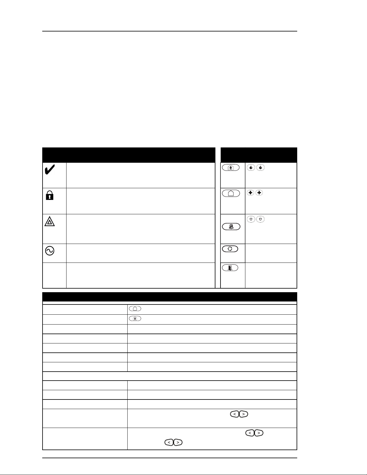
Statu s Lights
Ready - Indicates system normal. Must be on to arm the
system. All zones must be secured or bypassed and the
system disarmed for this light to activate.
Armed- Indicates the system is armed. If the Ready light and
the Armed light are both on, an Exit Delay is in progress.
Trouble - On indicates a system malfunction or tamper.
Flashing indicates that the keypad has a low battery
condition. Follow the instructions displayed or enter [*][2] to
view trouble. Correcting the trouble turns off the indicator.
AC Power - Indicates AC Power is present. The AC Power
light turns off when AC is absent.
Function
Keys
Stay
Arm
Away
Arm
Chime
Reset
Quick
Exit
Emergency Keys
Fire Alarm
Medical Alarm
Panic Alarm
Actio n Press
Away Arm
Stay Arm
for 2 seconds + [Access Code†]
for 2 seconds + [Access Code†]
Night Arm When armed in stay mode [*][1] + [Access Code†]
Disarm [Access Code]
No-Entry Arming [*][9] + [Access Code†]
Quick Arm /Quick Exit [*][0]
Cancel Arming Sequence [Access Code]
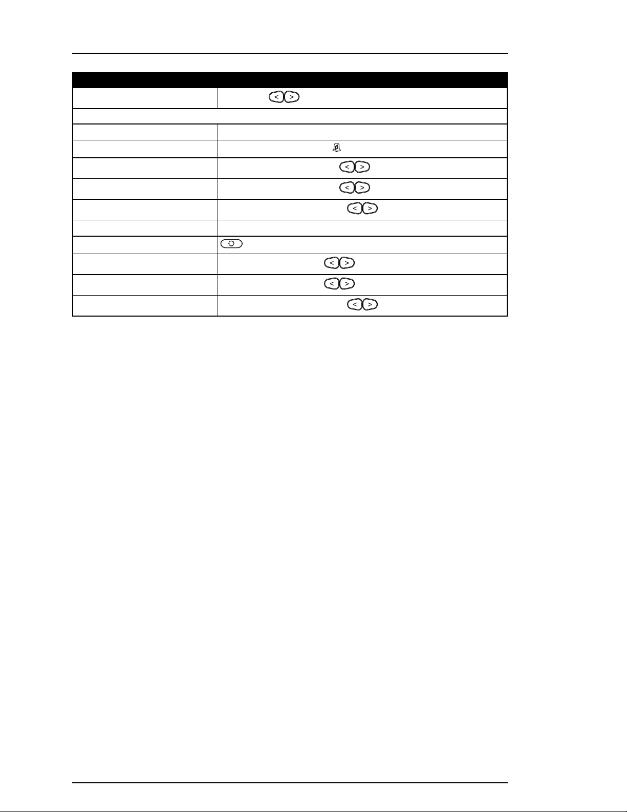
Bypassing - All bypass commands begin with [*][1] + [Access Code†]
Bypass Individual Zones [3 Digit Zone #]
Bypass All Open Zones [9][9][8]
Recall Last Bypass [9][9][9]
Clear Bypass
[0][0][0] OR [Scroll] Bypass Options + [*] + Clear Bypasses +
[*]
Program Bypass Group
[3 digit zone #s] + [9][9][5] OR [3 digit zone #s] + Bypass
Options + [*] + Prg Bypass Group + [*]
- 5 -
Page 6
Chapter 1
Actio n Press
Load Bypass Group
Common F un ctio ns
[9][9][1] OR Bypass Options + [*] + [Scroll] Bypass Group + [*]
Set Time and Date [*][6] [Master Code] + [0][1]
Turn Chime ON/OFF
Change Brightness
Change Contrast
Buzzer Volume
[*][4] + [Access Code†] OR
[*][6] [Master Code] + [1][2] +
[*][6] [Master Code] + [1][3] +
[*][6] + [Master Code] + [1][4] +
Add/Delete User [*][5] + [Master Code] + [Access Code] + 1
Reset Smoke Detectors
View Troubles
View Alarms
Perform System Test
OR [*][7][2]
[*][2] + [Access Code†] +
[*][3] + [Access Code†] +
[*][6] + [Master Code] + [0][4] +
† If configured by the installer.
- 6 -
Page 7

Chapter 2
2.0 Safety Instructions
North America
This equipment is cord connected, pluggable Type A, stationary with a non-detachable power supply
cord and must be installed by skilled persons only (persons who have training or experience in the
equipment technology, particularly in knowing the various energies and energy magnitudes used in the
equipment). It must be installed and used within an environment that has maximum pollution degree of 2,
over-voltages category II, in non-hazardous, indoor locations only.
Warning: This equipment has no mains on/off switch; if the equipment must be quickly disconnected, the
plug of the power supply cord serves as a means of disconnection; it is imperative that access to the
mains plug and associated mains socket/outlet is never obstructed.
International (EU, Australia, New Zealand)
This equipment is stationary-fixed and must be installed by Skilled Person only (Skilled Person is defined
as a person with relevant education or experience to enable him or her to identify hazards and to take
appropriate actions to reduce the risks of injury to themselves and others). It must be installed and used
within an environment that provides the pollution degree max 2, over voltages category II, in nonhazardous, indoor locations only.
Warning: When using equipment connected to the mains and/or to the telecommunication network, there
are basic safety instructions that should always be followed. Refer to the safety instructions provided with
this product and save them for future reference. To reduce the risk of fire, electric shock and/or injury,
observe the following.
l Do not attempt to open or service this product. Opening or removing the cover may expose you to
dangerous voltage or other risks. Servicing must be done by skilled persons only.
l l Use only authorized accessories with this equipment.
l Do not leave and/or deposit any object on the top of the cabinet of this equipment. The cabinet is
not designed to support any supplementary weight.
l Do not touch the equipment and its connected cables during an electrical storm; there may be a
risk of electric shock.
l l Never touch uninsulated wires or terminals unless the equipment has been disconnected from
the mains supply and from the telecommunication network.
l Ensure that cables are positioned so that accidents cannot occur. Connected cables must not be
subject to excessive mechanical strain.
l Do not spill any type of liquid on the equipment.
l Do not use the alarm system to report a gas leak if the system is near a leak.
l This equipment contains no user-serviceable parts, except for the keypad batteries.
l Dispose of used batteries as per local rules and regulations.
These safety instructions should not prevent you from contacting the distributor and/or the manufacturer
to obtain any further clarification and/or answers to any concerns.
- 7 -
Page 8

Chapter 3
3.0 The PowerSeries Pro Security System
The PowerSeries Pro has been designed to provide the greatest possible flexibility and convenience.
Read this manual carefully and have the installer provide instructions on how to operate the system and
which features have been implemented. All users of this system should be equally instructed in its use.
Fill out the "System Information" section with zone information and access codes and store this manual in
a safe place for future reference.
Note: The PowerSeries Pro security system includes specific false alarm reduction features and is
classified in accordance with ANSI/ SIA CP-01-2014 Control Panel Standard - Features for False Alarm
Reduction. Please consult the installer for further information regarding false alarm reduction features
built into the system as all are not covered in this manual.
3.1 General System Operation
This security system is made up of a PowerSeries Pro control panel, one or more keypads and various
sensors and detectors. The metal cabinet contains the system electronics and standby battery. The
keypad is used to send commands to the system and to display the current system status. The keypad(s)
are mounted in a convenient location inside the protected premises close to the entry/exit door(s). The
security system has several zones of area protection, each connected to one or more sensors (motion
detectors, glassbreak detectors, door contacts, etc.).
Note: Only the installer or service professional shall have access to the control panel.
3.2 Carbon Monoxide Detection
This equipment is capable of monitoring carbon monoxide detectors and providing a warning if carbon
monoxide is detected. Please read the Escape Planning guidelines in this manual and instructions that
are available with the carbon monoxide detector.
Note: Must be enabled and configured by installer.
Note: The equipment should be installed in accordance with NFPA 720.
3.3 Fire Detection
This equipment is capable of monitoring fire detection devices such as smoke detectors and providing a
warning if a fire condition is detected. Good fire detection depends on having adequate number of
detectors placed in appropriate locations. This equipment should be installed in accordance with NFPA
72 (N.F.P.A., Batterymarch Park, Quincey MA 02269). Carefully review the Escape Planning guidelines
in this manual.
Note: Must be enabled and configured by installer.
3.4 Testing the System
Tests all system keypad LEDs, keypad sounders, bells and/or sirens. To ensure the system continues to
function as intended, test your system weekly.
IMPORTANT: For UL HOME HEALTH CARE listed applications the system shall also be tested weekly
without AC power. To remove AC from the control unit, remove the screw from the restraining tab of the
plug in adapter and remove the adapter from AC outlet. After completing the test of the unit using only the
battery backup source, reconnect the plug in adapter and attach the screw through the restraining tab so
that the adapter is securely attached to the outlet.
IMPORTANT: Should the system fail to function properly contact the installation company.
IMPORTANT: All smoke detectors must be tested by the smoke detector installer once per year.
- 8 -
Page 9

Chapter 3
3.5 Performing a Keypad and Siren test
1. Press [*][6] and enter the [Master Code] to access User Functions.
Press [04] or use the scroll keys to navigate to System Test and press [*].
All keypad sounders, bells/sirens and keypad LEDs activate for two
seconds.
Press [#] to return to the Ready state.
Press (*) for <>
User Functions
Press (*) for <>
System Test
LCD Display
3.6 Monitoring
This system is capable of transmitting alarms, troubles and emergency information. If an alarm is initiated
by mistake, immediately call the central station to prevent an unnecessary response.
Note: For CP-01 systems, the monitoring function must be enabled by the installer before it is
operational. There is a communicator delay of 30 seconds in this control panel. It can be removed, or it
can be increased up to 45 seconds, at the option of the end-user by consulting with the installer. Fire type
alarms are normally reported without a delay.
3.7 Maintenance
Keep your alarm controller in optimal condition by following the instructions included within this manual
and/or marked on the product. The end user and/or installer are responsible for disposing of used
batteries according to local waste recovery and recycling regulations.
l Use the system test described in “Testing the System” to check the battery condition. We
recommend, however, that the standby batteries be replaced every 3-5 years.
l For other system devices such as smoke detectors, motion detectors or glassbreak detectors,
consult the manufacturer’s literature for testing and maintenance instructions.
l Lightly dust the security equipment with a slightly moistened cloth.
Note: Do not use abrasives, thinners, solvents or aerosol cleaners (spray polish) that may enter
through holes in the Alarm Controller and cause damage. Do not wipe the front cover with
alcohol, water or any other liquid.
3.8 Applicable models
This publication covers the following models:
Note: The X character refers to one of the following PG device operating frequencies: 4 refers to 433MHz,
8 refers to 868MHz, and 9 refers to 912-919MHz UL/ULC systems.
• HS3032
• HS3128
• HS3248
• HS2LCDPRO
• HS2LCDRFPROx
• HS2LCDWFPROx
• HS2LCDWFVPROx
• HS2TCHPRO
• HS2TCHPROBLK
- 9 -
Page 10

Chapter 4
4.0 Securing the Premises
The PowerSeries Pro provides multiple arming modes as described below:
Away Mod e
Stay Mode
Nigh t Mode
Note: Verify with the alarm company which modes are available. For SIA FAR listed panels, the Stay
Arming Exit Delay will be twice as long as the Away Arming Exit Delay.
Depending on the system configuration, there are multiple methods to arm the system.
Arm the system using a:
l Keypad
l 2-way Wireless Key
l Proximity Tag
4.1 Arming the System
The PowerSeries Pro system can be armed using a keypad, 2-way wireless key or a proximity tag.
Note: If your system is installed in accordance with SIA CP-01 Standard for False Alarm Reduction, the
security system arms in Stay Arm mode if the exit delay time expires and no one has exited the premises.
Use this mode when there is nobody on the premises. Away mode activates all
perimeter and interior sensors in the alarm system.
Use this mode when someone is on the premises. Stay mode partially activates the
alarm system by arming all perimeter sensors and bypassing all interior sensors.
Use when the perimeter and interior need to be armed but require limited movement
without activating the alarm (e.g., disable motion sensors in an area containing a
washroom). Night mode is similar to Stay mode but only bypasses internal sensors
configured as Night Zones.
4.1.1 Away Arming the System with the Keypad
Away mode activates the complete alarm system by:
• Arming all perimeter sensors.
• Arming all interior sensors.
4.1.1.1 Arming the system in Away mode
To arm the system in Away mode, complete the following steps:
1. Ensure that you close all windows and doors.
2. Ensure that the Ready indicator is on.
Note: You cannot arm the system until the Ready indicator is on.
3. Choose one of the following options:
• To quickly arm the system, press [*][0].
• To arm the system using the Away key, press and hold the Away key for 2 seconds. If it is
necessary, enter an access code, or present a proximity tag to the keypad reader.
If the system bypasses a zone, a warning appears on the keypad.
Note: For European installations (EN50131 certified), you can not arm the system without a valid user
code. If you do not have a valid user code, do not attempt to initiate the arming sequence for the alarm
system.
After you initiate the arming sequence, the system completes the following actions:
• The Armed indicator turns on.
• The Ready indicator remains lit.
• The Exit Delay time begins to count down.
• The keypad beeps six times, and continues to beep once each second. In the final 10 seconds, the
system beeps rapidly.
- 10 -
Page 11

Chapter 4
Note: For European installations (EN50131 certified), the Armed indicator turns on only after the Exit
Delay.
When the Exit Delay timer expires, the system is armed and the following actions occur:
• The Ready indicator turns off.
• The Armed indicator remains on.
• The keypad stops sounding.
Note: The installer configures the Exit Delay timer in accordance with the North American, Canadian, and
European certification requirements (UL, ULC, and EN50131).
4.1.1.2 Canceling the arming sequence
To cancel the arming sequence, complete the following step:
• Enter your access code, or present a proximity tag to the keypad reader.
4.1.2 Arming the system in Stay mode
Stay mode partially activates the alarm system by Arming all perimeter sensors, and bypassing all
interior sensors.
Note: For European installations (EN50131 certified), the Keypad Blanking feature activates after 30
seconds. You can see the status of the alarm system only after you enter a valid user code.
To arm the system in Stay mode, complete the following steps:
1. Ensure that you close all windows and doors.
2. Ensure that the Ready indicator is on.
3. Press and hold the Stay key for 2 seconds. If it is necessary, enter an access code, or present a
proximity tag to the keypad reader.
Note: Do not leave the premises.
If the system bypasses a zone, a warning appears on the keypad.
After you initiate the arming sequence, the system completes the following actions:
• The Armed indicator turns on.
• The Ready indicator remains lit.
• The Exit Delay timer begins counting down.
Note: For European installations (EN50131 certified), the Armed indicator turns on only after the Exit
Delay.
When the Exit Delay timer expires, the system is armed and the following actions occur:
• The Ready indicator remains lit.
• The Armed indicator remains on.
• The keypad stops sounding.
4.1.3 Canceling the arming sequence
To cancel the arming sequence, complete the following step:
• Enter your access code, or present a proximity tag to the keypad reader.
4.1.3.1 Silent Exit Delay
If you arm the system using the Stay key or the No Arming method [*] [9]:
• The warning beep is silenced
• The exit time doubles only for that exit period (CP-01 versions only).
Note: For non CP-01 versions, Standard Exit Time is used.
- 11 -
Page 12

Chapter 4
4.2 Arming the System with a 2-Way Wireless Key
If configured, the PowerSeries Pro system can be armed using the wireless keys provided with your
alarm system. To Arm the system with a 2-way wireless key, press the desired Arming mode button when
the system Ready indicator is on.
4.3 Arming the System with a Proximity Tag
Proximity tags can be used to arm/disarm the system or to perform a programmed function (e.g. used in
place of entering an access code or to unlock a storage room door).
To Arm the system with a proximity tag
• Present your proximity tag to a keypad with a proximity sensor when the system Ready indicator is
on.
• If configured by your installer, enter your access code.
Note: When arming with a proximity tag, the system arms in Away mode if you exit the premises. The
system arms in Stay mode if a motion sensor is installed and you don't exit the premises.
4.4 Night Arming
Night mode partially activates the alarm system by:
l Bypassing all internal sensors configured as Night zones.
l Arming all perimeter sensors.
l all other internal sensors.
Arming the system in Night mode is possible after the system has first been armed in Stay mode and [*][1]
is pressed at the keypad. The keypad can also be configured with a function key to arm the system in
Night Mode. To access armed interior areas when the system is armed in Night Mode, you must disarm
the system.
Note: Ensure that your installer has provided you with a list identifying all programmed night zones. Your
installer can configure a function key to arm the panel in Night mode without the system already being
armed in Stay mode.
4.4.1 Arming the system in Night mode
To arm the system in Night mode, complete the following steps:
1. Optional: If the system is configured, press and hold the Night Arm key for 2 seconds.
2. After you arm the system in Stay mode, press [*] [*] on any keypad, or press [*] [1].
3. Optional: If it is necessary, enter an access code or present a proximity tag to the keypad reader.
Note: The system arms all interior zones, except for devices that you program as Night Zones.
4.4.2 Disarming a system that is in Night mode
To disarm a system that is in Night mode, complete the following step:
• Enter your access code.
To gain access to interior areas that are armed during Night mode disarm the system by entering your
access code.
4.5 No-entry arming
The No-entry feature arms the system in Stay mode and completes the following actions:
• Removes the Entry Delay from configured zones.
• Arms all perimeter sensors.
• Bypasses all interior sensors.
Note: When you use the No-entry feature, an attempt to enter through a door or window creates an
instant alarm.
- 12 -
Page 13

Chapter 4
4.5.1 Arming the system using the No-entry arming feature
To arm the system using the No-entry arming feature, complete the following steps:
1. Ensure that the Ready indicator is on, and that the system is ready for arming .
2. Press [*] [9]. If it is necessary, enter an access code, or present a proximity tag to the keypad reader.
If the system bypasses a zone, a warning message appears on the keypad.
After you initiate the arming sequence, the system completes the following actions:
• The system flashes and has no entry delay.
• The keypad sounds with a fast beep.
• The system displays Exit Delay in Progress on the keypad.
When the Exit Delay timer expires, the system is armed .
4.5.2 Canceling the arming sequence
To cancel the arming sequence, complete the following step:
• Enter your access code, or present a proximity tag to the keypad reader.
4.6 Exit Delay Time Restart
This option restarts the exit delay timer if an entry/exit zone is tripped a second time before the end of the
exit delay. The exit delay timer can only be restarted once.
4.7 The Quick Exit feature
Use the Quick Exit feature if the system is already armed and you would like to leave without disarming
and rearming the system. Quick Exit uses the same hot keys as Quick Arming, and it provides you with a
2-minute exit delay to leave the premises without triggering an alarm. Once the door you leave from
closes, the quick exit timer will be canceled.
4.7.1 Exiting the premises using the Quick Exit feature
To exit a premises using the Quick Exit feature, complete the following steps:
1. If the system is armed and the Armed light is on, choose one of the following options:
• Press and hold the Quick Exit key for 2 seconds.
• Press [*] [0].
2. Exit the premises before the Exit Delay timer expires.
4.8 Bypassing Zones
Warning: If a zone is not operating properly, contact the installer immediately.
Bypassing zones intentionally unprotects specified zones the next time your system is armed. Depending
on the type of keypad, bypassed zones will be identified differently. Using an HS2LCD series keypad,
bypassed zones are indicated on the LCD screen as shown in the following table.
Note: For UL listed installations, zones can only be bypassed manually.
LCD Keypad Zone Indicatio ns
LCD Display Indication Description
Zone Label <>
none Zone is ready for arming.
Zone Label <>
O
Zone Label <>
B
O Zone is currently open. You may be unable to arm the
system.
B Zone is bypassed.
- 13 -
Page 14

Chapter 4
Bypassed zones:
l Must be configured before arming the system.
l Can be configured using a keypad.
l Allow for access to protected areas when the system is armed.
l Allow you to arm the system if a zone is temporarily out of service.
l Reduce the level of security.
l Will not sound an alarm.
l Are automatically cancelled each time the system is disarmed.
l Can be programmed together within bypass groups. For more information see “Bypass Groups”.
4.8.1 Additional Bypass Features
Recall Last
Bypass
Bypass All Open
Zones
Clear Bypass
Programming a
Bypass Group
Activating a
Bypass Group
Note: Ensure that no zones are unintentionally bypassed when arming the system.
Note: 24-hour zones can only be unbypassed manually.
Note: For security reasons, your installer has programmed the system to prevent you from bypassing
Recalls all zones that were bypassed the last time the bypass zone feature was
used.
Allows the user to quickly bypass all open zones with a single command.
Instantly clears all bypass conditions from the zones assigned to the partition.
Use when you consistently bypass the same zones. This feature allows you to store
in memory one group of bypassed zones per partition.
Loads a stored bypass group from memory.
certain zones (e.g., smoke detectors). For more information on fire zones see “Fire and CO Zone Types”.
4.8.1.1 Bypassing individual zones
To bypass individual zones, complete the following steps:
1. On the keypad, press [*] [1].
2. Optional: If it is necessary, enter an access code, or present a proximity tag.
3. To bypass a zone, choose one of the following options:
• Enter a three digit zone number.
• Use the [<] [>] keys to scroll to the zone, and press [*].
4. Optional: To toggle or un-do the bypassing of a zone, enter the three digit zone number, or press [*].
5. To exit Bypassing mode, press [*].
If the system is ready to arm, the Ready indictor is on.
4.8.1.2 Bypassing all open zones
To bypass all open zones, complete the following steps:
1. On the keypad, press [*] [1].
2. Optional: If it is necessary, enter an access code, or present a proximity tag to the keypad reader.
3. Choose one of the following options:
• Press [9] [9] [8].
• Use the [<] [>] keys to scroll to Bypass Options, and press [*].
• Use the [<] [>] keys to scroll to Bypass Open Zones, and press [*}
4. To exit Bypassing mode, press [*].
If the system is ready to arm, the Ready indicator is lit.
- 14 -
Page 15

Chapter 4
4.8.1.3 Recalling the last bypassed zones
To recall the last bypassed zones, complete the following steps:
1. On the keypad, press [*] [1].
2. Optional: If it is necessary, enter an access code, or present a proximity tag to the keypad reader.
3. Choose one of the following options:
• Press [9] [9] [9].
• Use the [<] [>] keys to scroll to Bypass Options, and press [*].
• Use the [<] [>] keys to scroll to Bypass Recall, and press [*].
4. To exit Bypassing mode, press [*].
If the system is ready to arm , the Ready indicator is on.
4.8.1.4 Clearing the Bypass Indication from all zones
To clear the Bypass Indication from all zones, complete the following steps:
1. On the keypad, press [*].
2. Optional: If it is necessary, enter an access code, or present a proximity tag to the keypad reader.
3. Choose one of the following options:
• Press [0] [0] [0].
• Use the [<] [>] keys to scroll to Clear Bypasses, and press [*].
4. To exit Bypassing mode, press [*].
4.9 Bypass Groups
Program frequently bypassed zones into the system as a bypass group. Using bypass groups avoids
individually bypassing each zone. One bypass group can be programmed per partition.
Note: This feature is not to be used in UL listed installations.
4.9.1 Programming a Bypass group
To program a Bypass group, complete the following steps:
1. On the keypad, press [*] [1].
2. Optional: If it is necessary, enter an access code or present a proximity tag to the keypad reader.
3. Choose one of the following options:
• Enter the three digit zone number of the zones you want to bypass.
• Scroll to the zone you want to bypass and press [*]
4. Choose one of the following options:
• To program the bypass group with the current bypassed zones, press [9] [9] [5].
• Use the [<] [>] keys to scroll to Bypass Options and press [*], and scroll to Program Bypass Group
and press [*].
5. To exit Bypassing mode, press [#].
4.9.2 Loading a Bypass group
To load a Bypass group, complete the following steps:
1. On the keypad, press [*] [1].
2. Optional: If it is necessary, enter an access code or present a proximity tag.
3. Choose one of the following options:
• Press [9] [9] [1], and if it is necessary, enter an access code or present a proximity tag.
- 15 -
Page 16

Chapter 4
• Use the [<] [>] keys to scroll to Bypass Options and press [*], and scroll to Bypass Group and press
[*].
4. To exit Bypassing mode, press [*].
4.10 Arming Troubles and Exit Faults
The PowerSeries Pro notifies you of troubles when you are attempting to arm the system or exit the
premises.
4.10.1 Arming Troubles
An error tone (long beep) sounds if the system is unable to arm. Arming trouble occur if:
l The system is not ready to arm (i.e., sensors are open).
l An incorrect user code is entered.
l A trouble is present and has not been viewed by the user. This operation must be enabled by the
installer.
4.10.2 Correcting an Arming error
1. Ensure all sensors are secure. Your keypad will identify any open sensors.
2. When the trouble light is on, enter [*][2] and enter [99] or scroll to the Acknowledge All Troubles
prompt and press [*]. NOTE: If your system has been programmed to prevent armingwhen a trouble
is present.
3. Try arming the system again.
4. If troubles persist contact your installer.
4.10.3 Audible Exit Faults
Note: This option must be enabled by your installer.
In an attempt to reduce false alarms, the Audible Exit Fault notifies you of an improper exit when arming
the system. Improper exits are caused by failing to securely close the Exit/Entry door.
Improper exits cause the following system notifications:
l The keypad emits one continuous beep.
l The bell or siren sounds for the duration of the entry delay until a valid user code is entered or
until the programmed Bell Time Out expires.
4.10.4 To Correct an Exit Fault
1. Re-enter the premises.
2. Disarm the system before the entry delay timer expires by entering your access code.
3. Follow the Away arming procedure again, making sure to close the entry/exit door properly. For
more details see: “Away Arming the System with the Keypad”.
4.11 Disarming the System
Depending on your system configuration, there are multiple methods you can use to disarm your system.
You can disarm the system using a keypad, 2-way wireless key or a proximity tag:
4.12 Disarming the system with a keypad
Note: When you enter the premises, the keypad sounds. To avoid an alarm condition, you must disarm
the system within a specific number of seconds.
To disarm the system with a keypad, complete the following step:
• Enter your access code, or present a proximity tag to the keypad reader.
4.13 Disarming the system with a 2-way Wireless Key
Note: When you enter the premises, the keypad sounds. To avoid an alarm condition, you must disarm
the system within a specific number of seconds.
To disarm the system with a 2-way Wireless Key, complete the following step:
• When the system is armed , and the Armed indicator is on, press the Disarm key.
- 16 -
Page 17

Chapter 4
Note: After you disarm a system with an HS2LCD keypad using a 2-way wireless key, ensure that you
check the alarm memory to determine if any alarms occurred during the armed period.
4.14 Disarming the system with a proximity tag
Note: When you enter the premises, the keypad sounds. To avoid an alarm condition, you must disarm
the system within a specific number of seconds.
To disarm the system with a proximity tag, complete the following step:
• When the system is armed , and the Armed indicator is on, present a proximity tag to the proximity
sensor on the keypad.
Note: The installer programs the Duration of Entry timer, and advises on the duration of the timer. Valid
entries are between 30 seconds and 4 minutes). For SIA CP-01 classified installations, the entry delay
must not exceed 45 seconds.
4.14.1 Disarming error
If your code is invalid, the system does not disarm and a 2-second error tone sounds. If this occurs, press
[#] and re-enter your access code.
- 17 -
Page 18

Chapter 5
Fire Alarm <>
Bells Silenced
5.0 Alarms
The system can generate different alarm sounds, each with a different purpose and priority.
Priority Type of Alarm What you hear
1 Fire Temporal (3 beeps then a pause) or pulsed siren (continuous beeping)
2 Carbon Monoxide 4 beeps, 5 second pause, 4 beeps
3 Intrusion (Burglary) Continuous siren
4 Flood 1 second on, 3 seconds off, repeating
Note: Medical alarm is silent, it only results in an alarm transmission to the monitoring station.
5.1 Emergency Keys
IMPORTANT: EMERGENCY USE ONLY!
Pressing both the emergency keys generates a Fire, Medical, or Panic Alarm, and alerts the monitoring
station. To generate a medical alarm, press both medical alarm keys simultaneously for 2 seconds. The
keypad beeps to indicate the alarm input has been accepted and sent to the monitoring station.
Fire Alarm
Medical Alarm
Panic Alarm
Verify with your alarm company that your system is equipped with emergency keys.
Having an optional audio verification module installed on your system allows the monitoring station to
open 2-way communication when notified of an alarm.
Note: Fire keys can be disabled by the installer.
5.2 Fire alarm
Warning: If the fire alarm sounds, follow your emergency evacuation plan immediately.
5.2.1 Silencing a fire alarm
If the fire alarm accidentally activates you can silence the alarm. To silence the alarm, complete the
following steps:
1. On the keypad, enter your access code.
2. Call your central station to avoid a fire dispatch.
5.2.2 Bells Silenced LCD display for fire alarms
If you silence a fire alarm by entering a user code, and the zone that initiated the fire alarm remains open,
a Bells Silenced message displays. The system automatically clears the message when all the fire zones
are restored on the system. When the Bells Silenced message displays, a user can still view all standard
base menu messages by using the manual Scroll button.
Note: The Bells Silenced message also overrides the automatic display of the Alarm Memory feature for
fire alarms.
Bells Silenced LCD d isplay
- 18 -
Page 19

Chapter 5
CO Alarm <>
Bells Silenced
5.3 Resetting Smoke Detectors
After an alarm condition, reset smoke detectors to exit the alarm condition.
Note: Verify with your alarm company if this function is required on your system.
To reset the sensors
1. Press and hold the reset key on the keypad for 2 seconds. If the reset is successful, the alarm
is cancelled.
2. If a smoke detector fails to reset, it may still be detecting an alarm condition. If unsuccessful, the
alarm will reactivate or continue. Contact your alarm system provider.
5.4 Carbon Monoxide Alarm - 4 beeps, long pause, 4 beeps
Warning: Carefully review your Carbon Monoxide Alarm Installation/User Guide to determine the
necessary actions required to ensure your safety and ensure that the equipment is operating correctly.
Incorporate the steps outlined in the guide into your evacuation plan.
Activation of your CO alarm indicates the presence of carbon monoxide (CO), which can be fatal. During
an alarm:
l The red LED on the CO detector flashes rapidly and buzzer sounds with a repeating cadence of 4
quick beeps, 5-second pause, 4 quick beeps.
l The siren connected to the control panel produces the same cadence as above.
l The keypad provides audible and visual indication of the CO alarm.
If the Carbon Mon oxide Alarm Sounds
1. Immediately move outdoors or to an open door/window.
2. Call emergency services or your fire department.
5.4.1 Bells Silenced LCD display for CO alarms
If you silence a CO alarm be entering a user code, and the zone that initiated the CO alarm remains
open, a Bells Silenced message displays. The system automatically clears the message when all the CO
zones are restored on the system. When the Bells Silenced message displays, a user can still view all
standard base menu messages by using the manual Scroll button.
Note: The Bells Silenced message also overrides the automatic display of the Alarm Memory feature for
CO alarms.
Bells Silenced LCD d isplay
5.5 Intrusion (Burglary) Alarm - Continuous Siren
Warning: If you are unsure of the source of the alarm approach with caution.
If the Intrusion alarm was accidental, complete the following steps:
1. Enter your Access Code to silence the alarm. If the code is entered within 30s (or the programmed
value of the alarm transmission delay) the transmission of the alarm to the monitoring station will be
cancelled.
2. Call your central station to avoid a dispatch.
5.6 Alarm Cancel Window
The control panel provides a period of time in which the user can cancel the alarm transmission
(minimum duration is 5 minutes). If the programmed alarm transmission delay has expired, canceling an
alarm sends a message to the monitoring station. Upon a successful transmission of the cancellation
message, the keypad beeps 6 times. Must be enabled and configured by the installer.
Note: For CP-01 systems, alarm transmission delay must not exceed 45 seconds.
- 19 -
Page 20

Chapter 5
5.7 Viewing Alarms in Memory
When an alarm occurs the keypad indicator illuminates. Viewing the Alarm Memory provides more
information on the sensor(s) that were activated.
To View Alarms in Memory
Press [*][3] or use the scroll keys to navigate to Alarm Memory and press [*].
5.7.1 Alarm Messages
LCD What it means
Burglary Verified Multiple burglary sensors were activated. Central station has been notified.
Burglary Not Verified A single burglary sensor was activated. Central station has been notified.
Hold-up Verified Multiple hold-up sensors were activated. Central station has been notified.
Hold-up Not Verified A single hold-up sensor was activated.
Fire Alarm Fire alarm has been triggered. Central station has been notified.
CO Alarm CO alarm has been triggered. Central station has been notified.
- 20 -
Page 21

Chapter 6
6.0 Wireless Keys
In addition to the keypad, the PowerSeries Pro system can be controlled using a variety of devices:
l 2-Way Wireless Keys
l Proximity Tags
6.1 Using 2-way Wireless Keys
Wireless keys allow users in close proximity of their premises the ability to readily arm/disarm their
system, and to call for help. When using compatible wireless keys there is one beep for arming and two
beeps for disarming. The wireless key buttons can also be programmed for various functions, including
Instant Stay Arm. Check with your installer for details.
Note: The panic feature has not been evaluated by UL for the PG9929/PG9939.
For additional information, refer to your 2-way Wireless Key Instruction Sheet.
6.2 Using Proximity Tags
Proximity tags can be used to arm/disarm the system, perform a programmed function and can also be
used in place of your user access code.
To operate, present the tag close to the tag reader icon ( ) on your keypad. The LED bar flashes 3
times upon a valid proximity tag being read by the keypad successfully.
Note: Proximity tags must be enrolled on the system (see "Enrolling and Deleting Proximity Tags").
- 21 -
Page 22

Chapter 7
7.0 Managing Users
The maximum number of access codes are as follows:
l 72 for HS3032
l 1000 for HS3128
l 1000 for HS3248
Each user access code can be:
l Uniquely labeled.
l Assigned a proximity tag. In order to operate, proximity tags must be enrolled in the system.
l Assigned to only operate specific partitions. For more information on partitions see: "Managing
Partitions".
l Configured with additional attributes. For more information see: "Configuring additional User
Options".
Note: Your installer configures all access codes to be either 4, 6, or 8 digits.
7.1 Access Code Types
The alarm system provides the following user access code types:
Cod e Add User Delete User Arm Disarm Access Codes User Functions Installer
Master
User
Supervisor
Duress
One-time user
All All Yes Yes Yes Yes No
No No Yes Yes No No No
All but Master All but Master Yes Yes Yes Yes No
No No Yes Yes No No No
No No Yes 1/day No No No
Installer and Master codes are system codes that can be changed but not deleted. The other codes are
user-defined and can be added or deleted as necessary. By default, access codes have the same
partition and attribute programming as the code used to program them.
Note: When using 8-digit access codes, the minimum number of variations are:
• 138888 for HS3032
• 100000 for HS3128
• 100000 for HS3248
There are no disallowed codes.
Master
Cod e
By default, the master code can access all partitions and can perform any keypad function.
This code can be used to program all access codes, including the supervisor and duress
codes. The master code number is [01].
User
Cod es
Supervisor
Cod es
This type of access code is used to arm and disarm assigned partitions and can access the
User Functions menu.
Use when you want to allow additional users to manage access codes [*5] or User
Functions [*6]. Supervisor codes created by the master code have the same attributes as
the master code. Supervisor codes created by another supervisor code have the same
attributes, except the supervisor attribute. After creation, attributes can be changed for all
supervisor codes. For information on how to program a supervisor code see "Configuring
additional User Options".
Duress
Cod es
A Duress Code is used if forced to access your keypad under threat. Duress codes function
the same as user access codes, except they transmit a Duress Report to your monitoring
station when used to perform any function on the system.
Duress codes cannot be used to change Access Codes [*5], User Functions [*6] or Installer
[*8] programming. For information on how to program a Duress Code, see "Configuring
additional User Options".
One Time
User Code
Used to grant someone one-time access to your home, i.e., a cleaning person or contractor.
The ability to disarm the system is reset at midnight or when the one-time user code is
keyed in by the master code user. For information on how to program a One Time User
Code, see "Configuring Additional User Options".
- 22 -
Page 23

Chapter 7
7.2 Opening the Access Codes menu
1. Press [*][5]
• OR
Press (*) for <>
Access Codes
LCD Display
• press [*] and use the scroll keys to navigate to Access Codes and
press [*] to select.
Enter Master or Supervisor code.
Enter User #
• or
Press (*) for <>
{User Label}
• scroll through the list of users and press [*].
To go back to the Ready state press [#].
7.3 Adding, Changing and Deleting Access Codes
Each configured user is assigned a number as follows:
• 01-72 for HS3032
• 01-1000 for HS3128
• 01-1000 for HS3248
A “-” beside a user ID indicates it is not programmed.
7.3.1 Adding or changing user access codes
To add or change user access codes, complete the following steps:
1. Enter the user number and press [*].
Enter a new 4, 6, or 8-digit access code. After entering a new code, the
display indication is changed to “P” from “-”. If a duplicate code is
Press (*) for < >
Access Code
Enter New Code
AAAA
LCD Display
entered, an error tone sounds. After the code is programmed, the
keypad returns to the previous menu.
To Delete a User Access Cod e LCD Display
Enter the user number and press [*].
Press [*]. The code is deleted and the flag is changed to “-” from “P”. After
the code is programmed, the keypad returns to the previous menu.
Note: Any proximity tags associated with deleted user codes must be re-enrolled.
Press (*) for <>
Access Code
Enter New Code
030516
7.4 Enrolling and Deleting Proximity Tags
When enrolling or deleting proximity tags for a user, the system provides a choice of options. For more
information see "Using Proximity Tags".
To Enroll a Proximity Tag LCD Display
1. From the desired user press [2] or scroll to Prox Tag and press [*].
2. If no tag is enrolled for this user you will be asked to present the tag
to the reader.
l If the card successfully enrolls the blue LED bar flashes.
l If the tag is invalid the following message is displayed.
Press (*) for <>
Prox Tag
Present Tag or
Press # to Exit
Tag Enrolled
Successfully
Invalid Tag
Not Enrolled
- 23 -
Page 24

Chapter 7
l If the tag is enrolled with another user the following message is
displayed.
To Delete a Proximity Tag
1. From the desired user press or scroll to Prox Tag and press [*].
2. If a Prox Tag is enrolled for this user you will be asked if you would
like to delete the Tag. Press [*] to delete the tag.
Duplicate Tag
Not Enrolled
LCD Display
Press (*) for <>
Prox Tag
* To Delete Tag
Press # to Exit
7.5 Naming a User
Adding or editing labels are accomplished by using the keypad to input the desired letters or numbers.
The following figure depicts the three letters and one number that corresponds to each keypad button.
The first press of the number key displays the first letter. The second press displays the second letter, etc.
[1] [2] [3]
A, B, C, 1 D, E, F, 2 G, H, I, 3
[4] [5] [6]
J, K, L, 4 M, N, O, 5 P, Q, R, 6
[7] [8] [9]
S, T, U, 7 V, W, X, 8 Y, Z, 9,0
[0]
Space
To Edit a User Lab el LCD Display
1. From the User Codes menu press [3] or scroll to User Labels and
press [*].
Press (*) for <>
User Labels
2. Use the arrow keys [<][>] to move the cursor to a blank space or
existing character.
3. Press the [#] key corresponding to the appropriate letter as shown in
the previous figure.
4. When the required letter or number is displayed use the arrow keys
to scroll to the next letter.
Program Name
{User 1 Label}
5. When finished, press the [*] key.
6. Use the [<][>] keys to scroll to save, then press [*].
7.6 Assigning a Partition to a User Code
User codes can be configured to have access only to specific partitions. For more information see
"Managing Partitions".
Note: Partitions are configured by your installer.
1. From the desired user press [4] or scroll to Partition Assign and
press [*].
2. Press [*] to select partition assignment for the user code, select Y
or N.
Press (*) for <>
Partition Assign
(*) To Toggle <>
{Partition Lb} Y
LCD Display
- 24 -
Page 25

Chapter 7
7.7 Configuring Additional User Options
Users can also be assigned the following feature options:
[1] Supervisor Code
[2] Duress Code
[3] Zone Bypass
[7] Bell Squ awk
Note: When using wireless keys to arm/disarm the system there will be:
[8] One Time Use
To Con figure Additional User Options LCD Display
1. From the desired user press [5] or scroll to User Options and press
[*].
2. Use the [<][>] keys to cycle through the User Options and press [*] to
toggle, configuring the displayed option.
For more information see "Access Code Types".
For more information see "Access Code Types".
Grants the user the ability to bypass zones.
Use to generate a bell squawk when arming/disarming the system.
l one bell squawk for arming
l two bell squawks for disarming.
l three squawk pairs when disarming with an alarm in memory.
For more information see "Access Code Types".
Press (*) for <>
User Options
(*) To Toggle <>
Bell Squawk Y
- 25 -
Page 26

Chapter 8
8.0 User Functions [*] [6]
The PowerSeries Pro allows for a variety of user configurable functions as listed below:
Event Buffer Auto Arm Time Late To Open Contrast Control User's Walk Test
Time and Date System Service/DLS Late To Open Time Buzzer Control Auto Arm/Disarm
Voice Chime User Call-Up Brightness Control Voice Prompt
Note: User Functions can only be modified when the system is disarmed.
To access the User Functio n menu LCD Display
1. Press [*][6]
• OR
press [*] and use the scroll keys to navigate to User Functions and press
[*] to select.
2. Enter Master code and scroll through the options listed above.
3. To go back to the Ready state press [*].
8.1 Event Buffer
The event buffer displays a list of the last 500 events on the HS3032, and the last 1000 events on the
HS3128/HS3248. You can only view the event buffer using an LCD keypad.
Press (*) for <>
User Functions
Present Tag or
Enter Code
To view the Event Buffer LCD Display
1. From the User Function menu [<][>] scroll to Event Buffer and press
[*].
2. Press [<][>] to scroll through the Event Buffer. When finished press [*]
to return to the Ready state.
Press (*) for <>
Event Buffer
000X-Message
Time/Date
8.2 Setting the Time and Date
To Set the Time and Date LCD Disp lay
1. From the User Function menu use the shortcut key [0][1] or press [<]
[>] to scroll to Time and Date and press [*].
2. Use the number keys to set the time and date. When finished press
[*] to return to the Ready state.
Select Option <>
Time and Date
HH:MM MM/DD/YY
11:12 01/14/13
8.3 Enabling/Disabling the Auto Arm/Disarm Feature
Note: This feature must be configured by installer.
To enable/disable Au to Arm/Disarm LCD Display
1. From the User Function menu use the shortcut key [0][2] or press [<]
[>] to scroll to Auto Arm/Disarm.
2. Press [*] to enable/disable the Auto Arm/Disarm feature.
3. When finished press [*] to return to the Ready state.
Press (*) for <>
Auto Arm/Disarm
Auto Arm/Disarm
is Enabled
Auto Arm/Disarm
is Disabled
or
- 26 -
Page 27

Chapter 8
8.4 Setting the Auto Arm Time
The system can be configured to auto arm at a specific time on each day of the week. If a specific time is
not configured for a day of the week the system will not arm automatically on that day.
Note: This feature must be configured by installer.
To Set the Au to Arm Time LCD Display
1. From the User Function menu use the shortcut key [0][3] or press [<]
[>] to scroll to Auto Arm Time.
2. Press [*] to open the days of the week sub menu. Scroll through the
days of the week and press [*] to set the time for that day.
3. Using a 24-hour format, set the desired time. After you enter the
fourth digit the screen will revert back to the previous day of the
Press (*) for <>
Auto Arm Time
Press (*) for <>
Sunday
Set 24Hr Time
Enter HH:MM 9999
week menu. Entering the time 9999 disables the Late-to-Open
feature for that day.
4. Continue setting the time for the desired days of the week. When
finished press [#] to return to the Ready state.
Note: If you set an invalid time the error tone will sound.
Set 24Hr Time
Enter HH:MM 9999
8.5 Allowing the Installer to Service your System Remotely - DLS
Occasionally, your installer may need to remotely access the Installer programming of your security
system using Downloading Software (DLS). In order for this to successfully occur, you may need to
manually allow access to your system.
Note: Access to this feature must be configured by installer.
To enable/disable System Service/DLS LCD Display
1. From the User Function menu use the shortcut key [05] or press[<][>]
to scroll to SystemServ/DLS.
2. Press [*] to enable/disable the SystemServ/DLS feature.
3. When finished press [#] to return to the Ready state.
Press (*) for <>
SystemServ/DLS
SystemServ/DLS
is Enabled
SystemServ/DLS
is Disabled
8.6 User Callup
Using DLS, User Call-up allows your system to make one attempt to connect to the installer’s remote
computer. For a successful connection, the remote computer must be waiting for the system’s call.
Note: Access to this feature must be configured by installer.
To perfo rm a User Callup LCD Display
1. From the User Function menu use the shortcut key [0][6] or press [<]
[>] to scroll to User Callup.
Press (*) for <>
User Callup
2. When finished press [#] to return to the Ready state.
8.7 Late to Open
The Late to Open feature provides notification if the alarm system is not disarmed by the programmed
time of day.
Note: Access to this feature must be configured by installer.
or
To enable/disable Late to Open LCD Display
1. From the User Function menu use the shortcut key [0][9] or press [<]
[>] to scroll to Late to Open.
2. Press [*] to enable/disable the Late to Open feature.
Press (*) for <>
Late to Open
Late to Open
is Enabled
or
- 27 -
Page 28

Chapter 8
3. When finished press [*] to return to the Ready state.
To set the Late to Open time LCD Display
1. From the User Function menu use the shortcut key [1][0] or press [<]
[>] to scroll to Late to Open Time.
2. Press [*] to open a days of the week sub menu. Scroll the days of the
week and press [*] to set the time for that day.
3. Using a 24-hour format, set the desired time. Once the fourth digit is
entered, the screen will revert back to the previous day of the week
Late to Open
is Disabled
Press (*) for <>
Late to Opn Time
Press (*) for <>
Sunday
Set 24Hr Time
Enter HH:MM 9999
menu. Entering the time 9999 disables the late to open feature for
that day.
4. Continue setting the time for the desired days of the week. When
finished press [#] to return to the Ready state.
Note: If you enter an invalid time the error tone will sound.
8.8 Changing the Brightness of the LCD keypad
To change the LCD b rightness LCD Display
1. From the User Function menu use the shortcut key [1][2] or press [<]
[>] to scroll to Bright Control and press [*].
2. Enter the 2-digit value or scroll to the desired brightness level and
press [*] to return to the previous menu.
3. Press [#] to return to the Ready state.
Press (*) for <>
Bright Control
Brightness <>
Level... XX
8.9 Changing the Contrast of the LCD keypad
To change the LCD co nt rast LCD Display
1. From the User Function menu use the shortcut key [1][3] or press [<]
[>] to scroll to Contrast Control and press [*].
2. Enter the 2-digit value or scroll to the desired contrast level and
press [#] to return to the previous menu.
Press (*) for <>
Contrast Control
Contrast <>
Level... XX
3. Press [#] to return to the Ready state.
8.10 Setting the Buzzer volume
To change Buzzer volume LCD Display
1. From the User Function menu use the shortcut key [1][4] or press [<]
[>] to scroll to Contrast Control and press [*].
2. Enter the 2-digit value or scroll to the desired volume level and press
[#] to return to the previous menu.
Press (*) for <>
Buzzer Control
Buzzer <>
Level... XX
3. Press [#] to return to the Ready state.
8.11 Setting the Voice Prompt volume
This feature is only available when using an HS2LCDWFVPRO wireless keypad.
To change Voice Prompt volume LCD Display
1. From the User Function menu use the shortcut key [1][5] or press [<]
[>] to scroll to Voice Prompt and press [*].
2. Enter the 2-digit value or scroll to the desired volume level and press
[#] to return to the previous menu.
3. Press [#] to return to the Ready state.
Press (*) for <>
Voice Prompt
Voice Prompt <>
Level... XX
- 28 -
Page 29

Chapter 8
8.12 Setting the Voice Chime volume
This feature is only available when using an HS2LCDWFVPRO wireless keypad.
To change Voice Chime volume LCD Display
1. From the User Function menu use the shortcut key [1][6] or press [<]
[>] to scroll to Voice Chime and press [*].
2. Enter the 2-digit value or scroll to the desired volume level and press
[#] to return to the previous menu.
3. Press [#] to return to the Ready state.
Press (*) for <>
Voice Chime
Voice Chime <>
Level... XX
8.13 Resetting the System
8.13.1 Engineer's Reset
If an alarm has occurred on your system, the system will not allow you to rearm (Ready light is OFF). If
"Reset Required" is displayed on your keypad, contact your installer. They will check and reset the
system for you.
Note: This feature must be enabled by your installer.
8.13.2 Remote (Anti-code) Reset
When configured by the installer, an alarm condition will cause the system to require a remote reset and
arming will no longer be possible after the system is disarmed. This feature ensures that the end user
contacts the monitoring station following an alarm condition. The system keypads will display that a
remote reset is required and will show a random 5-digit remote reset code. You must contact the
monitoring station and provide the code that's displayed on the keypad. The monitoring station operator
will provide a different 5-digit code that the user can enter at the system keypad, which will clear the
remote reset condition, allowing the panel to be armed again.
Some user functions are still available while the system is locked out. The user can loan the keypad to a
different partition, and can access [*][6] User Functions so the event buffer can be reviewed to determine
cause of the alarm condition. The [*][3] Alarms in Memory and [*][7] command output menus are also
available during the remote reset condition.
This feature is intended to be used with burglary zones. Fire alarms do not generate remote reset.
Each partition will generate a unique Remote Reset code on the system keypads and must be unlocked
separately.
8.14 Walk Test
This feature allows the user to verify the operation of system detectors and notify the central station that a
Walk Test is in progress.
Note: This feature must be enabled by the installer.
IMPORTANT: During a system (walk) test, do not activate any:
l Fire, Auxiliary or Police buttons
l Fire or CO sensors
A full system test is comprised of activating each sensor in turn. Open each door, window and walk in
areas with motion detectors. It is recommended you perform system tests during off-peak hours, such as
early morning or late evening. When a test is in progress, the Ready, Trouble and Armed LEDs flash.
To Initiate a Walk Test L CD Display
1. From the ready state press [*][6] and enter the [Master Code] to
access User Functions.
2. Press [08] or use the scroll keys [<][>] to navigate to Walk Test and
press [*]. The system activates all keypad sounders and bell/sirens
for two seconds and also notifies the central station that a walk test
has begun.
- 29 -
Press (*) for <>
User Functions
Press (*) for <>
Walk Test
Page 30

Chapter 8
3. Trigger each detector (zone) in sequence. A squawk occurs at the
keypad, all LEDs on the keypad will flash and the violation will be
recorded in the Event Buffer.
4. Restore zones. Press [*][6][Master Code][8] to end the Walk Test.
The system will notify the central station that the walk test has been
terminated.
Note: Fire zones, the 'F' key, and 2-wire smoke detectors are excluded from this test. Activation of these
zones will cause the system to exit the walk test then generate and transmit an alarm condition to the
monitoring station.
If a zone is not activated within 15 minutes of initiating the Walk Test, the system will automatically exit
the Walk Test and resume normal operation. An audible warning sounds the last 5 minutes to indicate
the Walk Test is ending.
Note: This feature is not available in CP-01 panels.
To Initiate/Cancel a Walk Test LCD Disp lay
1. From the User Function menu, use the shortcut key [08] or press [<]
[>] to scroll to Walk Test.
2. Press [*] to enable/disable the Walk Test feature.
Press (*) for <>
Walk Test
Walk Test
is Enabled
3. Or, when finished press [*] to return to the Ready state.
Walk Test
is Disabled
- 30 -
Page 31

Chapter 9
9.0 Managing Partitions
A partition is a limited area of the premises which operates independently from the other areas.
Partitioning a system can be beneficial if the property has outbuildings that need to be secured
independently of a main area or if the home has a separate apartment. Each partition can have its own
keypad, or a keypad can have access to all partitions. User access to partitions is controlled via access
code. A master code can access the entire system and partitions, while a user code is limited to assigned
partitions.
9.1 Partitions
Keypads can be configured to control an individual partition or all partitions.
Note: Access to this feature must be configured by installer.
9.1.1 Single Partition Operation
Single partition keypads provide access to alarm functionality for an assigned partition. Single partition
keypads behave as follows:
l Displays the armed state of the partition.
l Displays open zones, if assigned to the partition the keypad is on.
l Displays bypassed zones and allows zone bypassing or creating bypass groups of zones
assigned to the keypad partition.
l Displays system troubles (system low battery, system component faults/tampers).
l Displays alarms in memory that occurred on the partition.
l Allows the door chime to be enabled/disabled.
l System test (sounds bells/PGMs assigned to the partition).
l Label programming (zone, partition and user labels for the partition).
l Command output controls (outputs assigned to the partition, or global outputs such as smoke
detector reset).
l Temperatures.
9.1.2 Loaning a Keypad to Another Partition
Keypads can be loaned to operate on other partitions (LCD keypads only). When a keypad is loaned
from either the global state or from another partition, it may be configured to behave on the loaned
partition just as it would if it was originally assigned there.
An access code must be entered before loaning a keypad to another partition. An access code is also
required to perform any function on that partition.
To Loan a Keypad to Ano th er Partition LCD Display
1. Press and hold the [#] key for 2 seconds and enter the access code.
2. Scroll [<][>] to the desired partition, press [*] to select. The keypad is
temporarily loaned to this partition. If the keypad is inactive for more
than 30 seconds, it reverts to its original partition.
The status of each partition will be identified by a partition flag. For an explanation on partition flags, see
the following table.
Partitio n F lags
LCD Display Flag Description
1 2 3 4 5 6 7 8
R X A ! E - P N
R Partition is ready to be armed
X Partition is in exit delay
A Partition is armed
! Partition is in alarm
E Partition is in entry delay
- Partition is not configured
1-8 Partition number
1 2 3 4 5 6 7 8
R R - - - - - N
- 31 -
Page 32

Chapter 9
P Partition auto arm pre-alert
N Partition is not ready to be armed
Keypads can also be configured as global keypads, controlling all partitions. Global keypads must be
configured by your installer.
9.2 Fire and CO Zone Types
l If a Fire zone generates an alarm only the partition the fire zone is assigned to will go into alarm.
Other partitions retain their current state.
l If the [F] key on a global keypad is used to generate an alarm all enabled partitions will go into
alarm.
l One or more fire zones may be located on any partition.
l On alarm, the fire auto-scroll display appears on all partition keypads and on all global keypads.
Fire alarm silence and fire system reset may be done directly on any partition keypad. To silence
a fire or CO alarm from a global keypad requires that the global keypad be loaned to one of the
partitions.
- 32 -
Page 33

Press (*) for <>
Temperature
Basement <>
Motion 73°F
Chapter 10
10.0 Additional Features
10.1 Viewing a temperature in a zone
This feature displays the temperature for each active zone. To view the temperature in a zone, complete
the following steps:
Note: An installer must activate this feature.
1. On any partitioned keypad, from the Main menu press [*].
2. Choose one of the following options:
• To select a temperature, press [*].
• For quick access, press [*] [*], and scroll through the menu to view the temperature capable zones.
3. To exit, press [#].
LCD Displays for viewing the temperature in a zone
10.2 Turning the Chime ON/OFF
Turning the chime on audibly notifies you when an entry/exit sensor is activated.
To turn the Chime ON or OFF LCD Display
l
Press the Chime key or [*][4] to toggle the Chime function On
or Off for the current partition. An access code may be required to
change this setting.
Door Chime
Feature ON
Door Chime
Feature OFF
10.3 Audio Verification
Allows the monitoring station to initiate a 2-way audio (talk/listen) or 1-way audio (listen-in only) session
when an alarm has been received. This feature is used to verify the nature of the alarm or determine the
type of assistance required by the occupant.
Note: This is a supplementary feature that has not been investigated by UL/ULC.
Note: Must be enabled and configured by installer.
10.4 Visual Verification
Allows the monitoring station to use video clips captured from system motion cameras for verification of
any alarms.
Note: This is a supplementary feature that has not been investigated by UL/ULC.
Note: Must be enabled and configured by installer.
10.5 Command Outputs
While being useful for many applications, Command outputs are typically configured to operate items
such as garage doors or electric gates. Additionally, command outputs can be assigned to follow a
schedule configured by your installer.
This is a supplementary feature that has not been investigated by UL/ULC.
Must be configured by installer.
- 33 -
Page 34

Chapter 10
To Activate a Command Output LCD Disp lay
1. Press [*][7] and if required enter your [access code].
• OR
Output Control <>
Scroll to View
• press [*] and use the scroll keys to navigate to Output Control.
2. Press the number configured to the command output
• OR
Output
Activated
• use the scroll keys to navigate to the desired command output and
press [*].
To configure a Co mmand Output to Follow a Schedu le LCD Display
1. Press [*][7] then use the scroll keys to navigate to Follow Schedule
and press [*], followed by your access code.
• OR
• press [*][7][9][User Code].
2. Press the command output #(1-4) to select a schedule and if
required enter your [access code].
Output Control <>
Scroll to View
then
Press (*) to
Follow Schedule
Partition 1 <>
Command O/P 1 Y
• OR
• use the scroll keys to navigate to the desired command output and
press to toggle scheduling and if required enter your [access code].
10.6 Burglary Verification
The PowerSeries Pro system includes cross zone and sequential detection features that require an
activation on two or more zones, within a given time period, to generate a confirmed alarm and
immediate police response.
Note: This feature must be enabled and configured by your installer.
10.7 Call Waiting
The PowerSeries Pro system includes a programmable option for call waiting to prevent a call waiting
line from interfering with the alarm verification process. This option is disabled by default.
Note: This feature must be enabled and configured by your installer.
10.8 Fire Alarm Verification
Fire Alarm Verification is an available option for Fire zones. If configured, and the conditions for alarm
verification are met, the fire alarm sounds and an alarm transmission is sent to the monitoring station.
Note: This feature must be enabled and configured by your installer.
10.9 System Lockout Due To Invalid Attempts
If too many invalid access codes are entered, your system can be configured to automatically lockout
input from all keypads, wireless keys and proximity tags for a programmed duration. If this happens, wait
the programmed duration then try again.
When the system is locked out the following message is displayed.
LCD Display
Keypad Lockout
Note: This feature and lockout duration must be configured by your installer. Fire, Medical and Panic
keys are still active during a System Lockout.
- 34 -
Page 35

Chapter 11
11.0 Troubleshooting
Occasionally, you may have a problem with your Alarm Controller or telephone line. If this happens, your
Alarm Controller will identify the problem and displays an error message. Refer to the provided list when
you see an error message on the display. If additional help is required, contact your distributor for
service.
Note: There are no parts replaceable by the end-user within this equipment, except for the keypad
batteries. Dispose of used batteries as per local rules and regulations.
Trouble Conditions
When a trouble condition occurs your Alarm System identifies the problem and displays an error
message. Refer to the table below when you see an error message on the display. If additional help is
required, contact your distributor for service.
When the system detects a trouble condition the following occurs:
• The Trouble indicator turns on.
• The keypad beeps once every 10 seconds. Press the [*] key to silence the keypad beeps.
Press [*][2] to examine troubles. When viewing troubles, the trouble indicator flashes to identify the level
of trouble being viewed. One flash = level 1, two flashes = level 2 etc.
Arming of your system may be impeded by a trouble. To override this condition, enter [*][2], scroll to
Acknowledge All Troubles and press [*] or enter 999.
Trou ble
Con dition
Trouble
Level 1
Description Trou ble Types
Trou ble
Level 2
Trouble numbers are used to view the trouble. Trouble Notification identifies the range that may be
displayed on the keypad. When exploring the trouble levels, the Trouble indicator will flash to identify
which level you are currently viewing.
Service
Required
01 Assorted Trouble types.
Time and Date troubles can be
resolved by resetting the Time/Date.
To set Time/Date press [*][6][0][1].
For all other troubles call for service.
Bell Circuit 01
RF Jam 02
Loss of clock 04
Output 1 Fault 05
Warm Start
USB Wi-Fi
Connected
Power Unit Fail
System
Power Fail Bus
Repeater
Power Fail
3A Supply
Overcurrent Call for
Notificat ion
Level 3
Repeater
1-8
Power
Supply 1-4
service
- 35 -
Page 36

Chapter 11
Trou ble
Con dition
Trouble
Level 1
Description Trou ble Types
Battery Trouble 02 The system has detected a battery
trouble condition.
Call for service.
Trou ble
Level 2
Notificat ion
Low Battery 01 n/a
No Battery 02
n/a
Low Battery
04 Module 1-4
High-current
O/P
No Battery
05 Module 1-4
High-current
O/P
Low Battery
07 Module 1-4
1A Power
Supply
No Battery
1A Power
08 Power
supply 1-4
Supply
Low Battery
Bus Repeater
No Battery
Bus Repeater
Low Battery 1
3A Power
Supply
Low Battery 2
3A Power
Supply
No Battery 1
3A Power
Supply
No Battery 2
3A Power
Supply
10 Repeater
1-8
11 Repeater
1-8
13 Power
Supply
1-4
14 Power
Supply
1-4
15 Power
Supply
1-4
16 Power
Supply
1-4
Level 3
- 36 -
Page 37

Chapter 11
Trou ble
Con dition
Trouble
Level 1
Description Trou ble Types
Bus Voltage 03 A module has detected a low
voltage on its Corbus red terminal.
AC Troubles 04 The system is experiencing loss of
power.
Call for service.
If the building and/or neighbourhood
has lost electrical power, the system
will continue to operate on battery
for several hours.
Trou ble
Level 2
Notificat ion
Level 3
HSM2HOST 01 n/a
Keypad 02 Keypad 1-
16
Zone Expander 04 Zone
expander
1-30
1A Power
Supply
05 Power
Module 1-4
High-current
Output
06 Output
Module 1-4
System Area 07 n/a
Output
Expander
08 Module 1-
16
Audio Module 09 n/a
8 I/O Module 10 Module 1-
30
Bus Repeater 11 Repeater
1-8
Bus Fault
Bus Repeater
3A Power
Supply
12 Repeater
1-8
13 Power
Supply 1-4
Zone 01 Zone label
or 001-248
Keypad 02 Keypad 1-
16
Siren 03 Siren 1-16
Repeater 04 Repeater
1-8
Power Supply 05 Power
supply 1-4
High-current
Output
06 Output
terminal 14
System Area 07 n/a
Bus Repeater 08 Repeater
1-8
3A Power
Supply
09 Power
Supply 1-4
- 37 -
Page 38

Chapter 11
Trou ble
Con dition
Trouble
Level 1
Description Trou ble Types
Device Faults 05 The system has detected an issue
with one or more connected
devices. Call for service.
Device Battery 06 The system detected an issue with
one or more device batteries. For
zone, keypad and wireless key
battery troubles see the
accompanying documentation for
how to change the batteries.
Device Tampers 07 The system has detected a tamper
condition with one or more devices
on the system.
Call for service.
RF Delinquency 08 The system has detected wireless
signal interference that is causing
improper system operation.
Call for service.
Trou ble
Level 2
Notificat ion
Level 3
Zone 01 Zone label
or 001-248
Keypad 02 Keypad 1-
16
Siren 03 Siren 1-16
Repeater 04 Repeater
1-8
Device Mask 06 Zone 001-
248
Gas 07 Zone 001-
248
Heat 08 Zone 001-
248
CO 09 Zone 001-
248
Freeze 10 Zone 001-
248
Probe
Disconnected
11 Zone 001-
248
Fire 12 Zone 001-
248
Zone 01 Zone label
or 001-248
Keypad 02 Keypad 1-
16
Siren 03 Siren 1-16
Repeater 04 Repeater
1-8
User 05 Wireless
key 1-32
Zone 01 Zone label
or 001-248
Keypad 02 Keypad 1-
16
Siren 03 Siren 1-16
Repeater 04 Repeater
1-8
Audio Station 05 Station 1-4
Zones 01 Zone label
or 001-248
Keypad 02 Keypad 1-
16
Siren 03 Siren 1-16
Repeater 04 Repeater
1-8
- 38 -
Page 39

Chapter 11
Trou ble
Con dition
Module
Supervision
Trouble
Level 1
Description Trou ble Types
09 The system has detected a
supervisory trouble condition with
one or more modules on the system.
Call for service.
Module Tampers 10 The system has detected a tamper
condition with one or more modules
on the system. Call for service.
Trou ble
Level 2
Notificat ion
Level 3
HSM2HOST 01 n/a
Keypad 02 Keypad 1-
16
Zone Expander 04 Expander
1-30
Power
Supply
High-current
Output
05 Power
Supply 1-4
06 Output
terminal 14
Output
Expander
08 Output
module 116
Audio Module 09
I/O Module 10 Module 1-
30
Bus Repeater 11 Repeater
1-8
3A Supply 12 Power
Supply 1-4
HSM2HOST 01 n/a
Keypad 02 Keypad 1-
16
Zone Expander 04 Zone
Expander
1-30
Power
Supply
High-current
Output
05 Power
Supply 1-4
06 Output
terminal 14
Output
Expander
08 Output
module 116
Audio Module 09 n/a
I/O Module 10 Module 1-
30
Bus Repeater 11 Repeater
1-8
3A Power
Supply
12 Power
Supply 1-4
- 39 -
Page 40

Chapter 11
Trou ble
Con dition
Trouble
Level 1
Description Trou ble Types
Communications 11 The system has detected a
communication trouble. Call for
service.
Not Networked 12 The system has detected a network
trouble condition with one or more
modules on the system.
If the trouble does not restore within
20 minutes, call for service.
AUX Trouble
13
The system has detected a trouble
on the AUX terminal.
Limited
Exceeded
14 The system detects incompatibility
with third-party firmware.
Trou ble
Level 2
Notificat ion
Level 3
TLM 01 n/a
FTC 02 Receiver
1-4
SIM Lock 03 n/a
Cellular 04 n/a
Ethernet 05 n/a
Receiver 06 Receiver
1-4
Supervision
Receiver
07 Receiver
1-4
Alt Comm Fault 09 n/a
Alt Comm FTC 10 Receiver
1-4
Zone 01 Zone label
001-248
Keypad 02 Keypad 1-
16
Siren 03 Siren 1-16
Repeater 04 Repeater
1-8
User 05 Users
01-1000
Zone 01 Zone
Power
Supply
High-current
05 Power
Supply 1-8
06 Module 1-4
O/P
System Area 07 n/a
8 I/O Module 10 Module 1-
30
Bus Repeater 11 Repeater
1-8
3A Power
Supply Aux 1
3A Power
Supply Aux 2
12 Aux 1
Trouble
13 Aux 2
Trouble
Interactive Zone 01 n/a
Interactive Par 02 n/a
- 40 -
Page 41

Chapter 12
12.0 Reference Sheets
Fill out the following information for future reference and store this guide in a safe place.
12.1 System Information
o [F] FIRE
o [M] MEDICAL
o [P] PANIC
The Exit Delay Time is _______ seconds.
The Entry Delay Time is _______ seconds.
12.2 Service Contact Information
Central Station Information
Account #: _____________________ Telephone #: _____________________
Installer Information:
Company: _____________________ Telephone #: _____________________
Battery Installation / Service Date:
___________________________________
___________________________________
___________________________________
IMPORTANT: If you suspect a false alarm signal has been sent to the central monitoring station, call the
station to avoid an unnecessary response.
- 41 -
Page 42

12.3 Access Codes
Master Code [01] : _________________________
Code Access Code Code Access Code Code Access Code Code Access Code
Note: Copy this page as needed to record additional access codes.
- 42 -
Page 43

12.3.1 Sensor/Zone Information
Sensor Protected Area Sen sor Type Sensor Protected Area Sensor T ype
Note: Copy this page as needed to record additional zone information..
- 43 -
Page 44

Chapter 13
13.0 Locating Detectors and Escape Plan
The following information is for general guidance only and it is recommended that local fire codes and
regulations be consulted when locating and installing smoke and CO alarms.
13.1 Smoke Detectors
Research has shown that all hostile fires generate smoke to a greater or lesser extent. Experiments with
typical fires in homes indicate that detectable quantities of smoke precede detectable levels of heat in
most cases. For these reasons, smoke alarms should be installed outside of each sleeping area and on
each storey of the home.
The following information is for general guidance only and it is recommended that local fire codes and
regulations be consulted when locating and installing smoke alarms.
It is recommended that additional smoke alarms beyond those required for minimum protection be
installed. Additional areas that should be protected include: the basement; bedrooms, especially where
smokers sleep; dining rooms; furnace and utility rooms; and any hallways not protected by the required
units. On smooth ceilings, detectors may be spaced 9.1m (30 feet) apart as a guide. Other spacing may
be required depending on ceiling height, air movement, the presence of joists, uninsulated ceilings, etc.
Consult National Fire Alarm Code NFPA 72, CAN/ULC-S553-02 or other appropriate national standards
for installation recommendations.
l Do not locate smoke detectors at the top of peaked or gabled ceilings; the dead air space in these
locations may prevent the unit from detecting smoke.
l Avoid areas with turbulent air flow, such as near doors, fans or windows. Rapid air movement
around the detector may prevent smoke from entering the unit.
l Do not locate detectors in areas of high humidity.
l Do not locate detectors in areas where the temperature rises above 38ºC (100ºF) or falls below
5ºC (41ºF).
l Smoke detectors must always be installed in USA in accordance with Chapter 29 of NFPA 72, the
National Fire Alarm Code: 29.5.1.1.
Where required by applicable laws, codes, or standards for a specific type of occupancy, approved
single- and multiple-station smoke alarms shall be installed as follows:
1. In all sleeping rooms and guest rooms.
2. Outside of each separate dwelling unit sleeping area, within 6.4 m (21 ft) of any door to a sleeping
room, the distance measured along a path of travel.
3. On every level of a dwelling unit, including basements.
4. On every level of a residential board and care occupancy (small facility), including basements and
excluding crawl spaces and unfinished attics.
5. In the living area(s) of a guest suite.
6. In the living area(s) of a residential board and care occupancy (small facility).
Figure 1
Figure 2
Figure 3
- 44 -
Page 45

Chapter 13
Figure 3a
Figure 4
13.2 Fire Escape Planning
There is often very little time between the detection of a fire and the time it becomes deadly. It is very
important that an emergency escape plan be developed and rehearsed.
l Study the possible escape routes from each location within the house. Since many fires occur at
night, special attention should be given to the escape routes from sleeping quarters.
l Escape from a bedroom must be possible without opening the interior door.
Consider the following when making your escape plans:
l Make sure that all border doors and windows are easily opened. Ensure that they are not painted
shut, and that their locking mechanisms operate smoothly.
l If opening or using the exit is too difficult for children, the elderly or handicapped, plans for rescue
should be developed. This includes making sure that those who are to perform the rescue can
promptly hear the fire warning signal.
l If the exit is above the ground level, an approved fire ladder or rope should be provided as well
as training in its use.
l Exits on the ground level should be kept clear. Be sure to remove snow from exterior patio doors
in winter; outdoor furniture or equipment should not block exits.
l Each person should know the predetermined assembly point where everyone can be accounted
for (e.g., across the street or at a neighbor's house). Once everyone is out of the building, call the
fire department.
l A good plan emphasizes quick escape. Do not investigate or attempt to fight the fire, and do not
gather belongings as this can waste valuable time. Once outside, do not re-enter the house. Wait
for the fire department.
l Write the fire escape plan down and rehearse it frequently so that should an emergency arise,
everyone will know what to do. Revise the plan as conditions change, such as the number of
people in the home, or if there are changes to the building’s construction.
l Make sure your fire warning system is operational by conducting weekly tests. If you are unsure
about system operation, contact your installer.
We recommend that you contact your local fire department and request further information on fire safety
and escape planning. If available, have your local fire prevention officer conduct an in-house fire safety
inspection.
Figure 5
- 45 -
Page 46

Chapter 13
13.3 Carbon Monoxide Detectors
Carbon monoxide is colorless, odorless, tasteless, and very toxic, it also moves freely in the air. CO
detectors can measure the concentration and sound a loud alarm before a potentially harmful level is
reached. The human body is most vulnerable to the effects of CO gas during sleeping hours; therefore,
CO detectors should be located in or as near as possible to sleeping areas of the home. For maximum
protection, a CO alarm should be located outside primary sleeping areas or on each level of your home.
Figure 5 indicates the suggested locations in the home.
Do NOT place the CO alarm in the following areas:
l Where the temperature may drop below -10ºC or exceed 40ºC
l Near paint thinner fumes
l Within 5 feet (1.5m) of open flame appliances such as furnaces, stoves and fireplaces
l In exhaust streams from gas engines, vents, flues or chimneys
l Do not place in close proximity to an automobile exhaust pipe; this will damage the detector
PLEASE REFER TO THE CO DETECTOR INSTALLATION AND OPERATING INSTRUCTION SHEET
FOR SAFETY INSTRUCTIONS AND EMERGENCY INFORMATION.
- 46 -
Page 47

14.0 Regulatory Agency Statements
14.1 FCC COMPLIANCE STATEMENT
CAUTION: Changes or modifications not expressly approved by Digital Security Controls could void your authority to use this equipment.
This equipment has been tested and found to comply with the limits for a Class B digital device, pursuant to Part 15 of the FCC Rules. These limits are designed to
provide reasonable protection against harmful interf erence in a residential installation. This equipment generates, uses and can radiate radio frequency energy and,
if not installed and used in accordance with the instructions, may cause harmful interfer ence to radio communications. However, there is no guarantee that
interference will not occur in a particular installation. If this equipment does cause harmful interference to radio or television reception, which can be determined
by turning the equipment off and on, the user is encouraged to tr y to correct the interference by one or more of the f ollowing measures:
- Re-orient the receiving antenna.
- Increase the separation between the equipment and receiver.
- Connect the equipment into an outlet on a circuit different from that to which the receiver is connected.
- Consult the dealer or experienced radio/television technician for help.
The user may find the following booklet prepared by the FCC useful: 'How to Identify and Resolve Radio/Television Interference Problems'. This booklet is
available f rom the U.S. Government Printing Off ice, Washington D.C. 20402, Stock # 004- 000-00345-4.
The keypads represented in this manual can be used with the following Control Units: HS3032, HS3128, and HS3248
14.2 IMPORTANT INFORMATION
This equipment complies with Part 68 of the FCC Rules and, if the product was approved July 23, 2001 or later, the requirements adopted by the ACTA. On the
side of this equipment is a label that contains, among other information, a product identifier. If r equested, this number must be provided to the Telephone Company.
HS3032 Product Identifier US:F53AL01AHS3256
HS3128 Product Identifier US:F53AL01AHS3256
HS3248 Product Identifier US:F53AL01AHS3256
USOC Jack: RJ-31X
Telephone Connection Requirements
A plug and jack used to connect this equipment to the premises wiring and telephone network must comply with the applicable FCC Par t 68 rules and requirements
adopted by the ACTA. A compliant telephone cord and modular plug is provided with this product. It is designed to be connected to a compatible modular jack that
is also compliant. See installation instructions for details.
Ringer Equivalence Number (REN)
The REN is used to determine the number of devices that may be connected to a telephone line. Excessive RENs on a telephone line may result in the devices not
ringing in response to an incoming call. In most but not all areas, the sum of RENs should not exceed five (5.0). T o be certain of the number of devices that may be
connected to a line, as determined by the total RENs, contact the local Telephone Company. For products approved after July 23, 2001, the REN for this product is
part of the product identifier that has the format US: AAAE Q##TXXXX. The digits represented by ## are the REN without a decimal point (e.g., 03 is a REN of
0.3). For ear lier products, the REN is separately shown on the label.
14.3 Incidence of Harm
If this equipment causes harm to the telephone network, the telephone company will notify you in advance that temporary discontinuance of service may be
required. But if advance notice is not practical, the T elephone Company will notify the customer as soon as possible. Also, you will be advised of your right to file
a complaint with the FCC if you believe it is necessary.
14.4 Changes in Telephone Company Equipment or Facilities
The T elephone Company may make changes in its facilities, equipment, operations or procedures that could affect the operation of the equipment. If this happens
the Telephone Company will provide advance notice in order for you to make necessar y modifications to maintain uninterrupted service.
14.5 Equipment Maintenance Facility
If trouble is experienced with this equipment f or repair or warranty information, contact the facility indicated below. If-the equipment is causing harm to the
telephone network, the Telephone Company may request that you disconnect the equipment until the problem is solved. This equipment is of a type that is not
intended to be repaired by the end user. Tyco Atlanta Distribution Center, 2600 West Pointe Dr ., Lithia Springs, GA 30122
14.6 Additional Information
Connection to party line service is subject to state tariffs. Contact the state public utility commission, public service commission or corporation commission for
information. Alarm dialing equipment must be able to seize the telephone line and place a call in an emergency situation. It must be able to do this even if other
equipment (telephone, answering system, computer modem, etc.) already has the telephone line in use. To do so, alarm dialing equipment must be connected to a
properly installed RJ-31X jack that is electrically in ser ies with and ahead of all other equipment attached to the same telephone line. Proper installation is depicted
in the figure below. I f you have any questions concerning these instructions, you should consult your telephone company or a qualified installer about installing the
RJ-31X jack and alarm dialing equipment for you.
- 47 -
Page 48

14.7 INNOVATION, SCIENCE & ECONOMIC DEVELOPMENT CANADA (ISED CANADA)
NOTICE: The models HS3032, HS3128, and HS3248 meet the applicable ISED Canada Terminal Equipment T echnical Specifications. This is confirmed by the
registration number. T he abbreviation, ISED, before the registration number signifies that registration was performed based on a Declar ation of Conformity
indicating that ISED Canada technical specifications were met. I t does not imply that ISED Canada approved the equipment.
The Ringer Equivalence Number ( REN) for this ter minal equipment is 0.1. The REN assigned to each terminal equipment provides an indication of the maximum
number of terminals allowed to be connected to a telephone interface. The termination on an interface may consist of any combination of devices subject only to
the requirement that the sum of the Ringer Equivalence Numbers of all devices does not exceed 5.
HS3032 Registration number I C:160A-HS3256
HS3128 Registration number I C:160A-HS3256
HS3248 Registration number IC:160A-HS3256
14.8 FCC AND ISED CANADA FOR WIRELESS KEYPADS
Warning: To comply with FCC and ISED Canada RF exposure compliance requirements, the HS2LCDRFPRO9 or HS2LCDWFPRO9, and HS2LCDWFVPRO9
keypads should be located at a distance of at least 20 cm from all persons during normal operation. The antennas used for this product must not be co-located or
operated in conjunction with any other antenna or tr ansmitter. This device complies with FCC Rules Part 15 and with ISED Canada license-exempt RSS standard
(s). Operation is subject to the following two conditions: (1) This device may not cause harmful interf erence, and (2)this device must accept any interfer ence that
may be received or that may cause undesired operation.
ISED:160A – HS2KRFP9
Models: HS2LCDRFPRO9, HS2LCDWFPRO9, HS2LCDWFVPRO9 (operating in 912-919MHz band) are compliant with applicable FCC Part 15.247 and IC
RSS-210 rules.
The term “I SED” before the radio certification number only signifies that ISED Canada technical specifications wer e met.
AVERTISSEMENT! Pour répondre aux exigences de conformité de la FCC et ISDE Canada sur les limites d'exposition aux radiofréquences (RF), les clavier
HS2LCDRFPRO9 ou HS2LCDWFPRO9, HS2LCDWFVPRO9 doivent être installés à une distance minimale de 20 cm de toute personne lors de leur
fonctionnement usuel. Ces derniers ne doivent pas être situés au même endroit, ni être en fonction avec une autre antenne ou un autre transmetteur. Le present
appareil est conforme aux CNR ISDE Canada applicables aux appareils radio exempts de licence. L'exploitation est autorisee aux deux conditions suivantes: (1)
l'appareil ne doit pas produire de brouillage, et ( 2) l'utilisateur de l'appareil doit accepter tout brouillage radioelectrique subi, meme si le brouillage est susceptible
d'en compromettre le fonctionnement.
14.9 EN Compliance
This product meets the requirements of Class II, Grade 3 equipment as per EN 50131-1:2006 + A1:2009 +A2:2017 Standard. This product is suitable f or use in
systems with the following notification options:
- A (use of two remotely powered warning devices and single path SP3 internal dialer or Ethernet path or plug-in cellular module required),
- B (self powered warning device (wireless siren) and single path SP3 internal dialer or Ethernet path or plug-in cellular module required),
- C (dual path DP2 internal dialer and alternate Ethernet or plug-in cellular communicator required)
- D (single path SP4 inter nal Ethernet path or plug-in cellular communicator with encryption enabled required)
- E (dual path DP3 internal Ethernet path and plug-in cellular communicator required)
The Model HS3032, HS3128, and HS3248 Contr ol panels have been certif ied by Telefication according to EN50131-1:2006 + A1:2009 +A2:2017, EN50131-3:2009
Type B, EN50131-6:2017 Type A, EN50131-10:2014 and EN50136-2:2013 for Gr ade 3, Class II, ATS Configur ations SP3 (phone line path only), SP4 (Ethernet or
cellular path only), DP2 ( dual path with phone line primary path and Ethernet or Cellular secondary path) and DP3 (dual path with Ethernet or Cell primary path
and Cellular or Ethernet as secondary path.
14.10 EUROPEAN CE COMPLIANCE STATEMENT
This product is in conformity with the Electromagnetic Compatibility Directive 2014/30/EU, the Low Voltage Directive 2014/35/EU, and the ROHS2 Directive
2011/65/EU.
SIMPLIFIED EU DECLARATION OF CONFORMITY
Hereby, Tyco Safety Pr oducts Canada Ltd declares that the radio equipment type is in compliance with Directive 2014/53/EU. The full text of the EU declarations
of conformity for the models mentioned below are available at the following internet addresses:
HS2LCDPRO: http://dsc.com/pdf /1903004
HS2LCDRFPRO8: http://dsc.com/pdf/1903005
HS2LCDWFPRO8_HS2LCDWFVPRO8: http://dsc.com/pdf/1903006
HS2TCHPRO(BLK): http://dsc.com/pdf/1903007
Frequency Band / Maximum Power
g1 433.22MHz – 434.62MHz/10mW
h1.4 868.0MHz – 868.6MHz/10mW
h1.5 868.7MHz – 869.2MHz/10mW
a3 119MHz – 135MHz - 66 dbµA/m @10m
- 48 -
Page 49

European single point of contact: T yco Safety Products, Voltaweg 20, 6101 XK Echt, Netherlands
14.11 UK Compliance Statement
In the UK this product is suitable for use in systems installed to conform to PD 6662:2017 at Grade 3 and environmental class II with the following notification
options: A, B, C, D, E .
Where HS3032, HS3128, and HS3248 are used with a single path signaling method (such as the Integrated Digital Dialer), please note the following limitation:
Important
Your attention is drawn to the fact that failure or compromise of single path signaling cannot be passed to the police. While the failure persists, subsequent alarms
cannot be notified to the alarm receiving centre and passed to the police.
Setting Methods
The HS3032, HS3128, and HS3248 are capable of supporting the completion of the full setting procedure by the following methods:
a) push button switch, mounted outside the supervised premises; or b) protective switch (i.e., door contact) fitted to the final exit door of the alar med premises or
area. The setting procedure is a two-stage process of initiating the setting procedure within the supervised premises (e.g., using Mini Prox Tag (MPT) or user
code) followed by completion of setting by one of the two methods mentioned above. Please check with the Installer which method has been enabled for your
system.
Unsettin g Methods
The HS3032, HS3128, and HS3248 are capable of supporting the following unsetting methods in accordance with BS8243:
6.4.2 Prevention of entry to the supervised premises before the alarm system is unset. Unsetting using remote key before entering the supervised premises causes or
permits the initial entry door to be unlocked.
6.4.5 Completion of unsetting using a digital key (e.g., MPT or PG8929, PG8939, PG8949) either before entering the protected premises (use PG8929, PG8939,
PG8949) or after entering the protected premises (use MPT). The entry delay is activated if the initial entry door is opened before the HS3032, HS3128, HS3248
has been unset. During the entry time, it is possible to unset the alar m system using a digital key only. Complete unsetting before programmed entry delay expires.
Important
If using a remote device to remotely set/unset your intruder alarm system, your attention is drawn to the fact that whenever a premises is unattended but its intruder
alarm system(s) is (are) not fully set, any related insur ance cover might be inoperative. For advice on this matter, it is r ecommended that you consult your insurer
(s).”
- 49 -
Page 50

Chapter 15
15.0 EULA
IMPORTANT - READ CAREFULLY: DSC Software purchased with or without Products and Components is copyrighted and is
purchased under the following license terms:
This End-User L icense Agreement (“EULA”) is a legal agreement between You (the company, individual or entity who acquired
the Software and any related Har dware) and Digital Security Controls, a division of Tyco Safety Products Canada Ltd. ( “DSC”),
the manufacturer of the integrated security systems and the developer of the software and any related products or components
(“HARDWARE”) which You acquired.
If the DSC software product (“SOFTWARE PRODUCT” or “SOFT WARE”) is intended to be accompanied by HARDWARE,
and is NOT accompanied by new HARDWARE, You may not use, copy or install the SOFTWARE PRODUCT. T he
SOFTWARE PRODUCT includes computer softwar e, and may include associated media, printed materials, and “online” or
electronic documentation.
Any software provided along with the SOFT WARE PRODUCT that is associated with a separate end-user license agreement is
licensed to You under the terms of that license agreement.
By installing, copying, downloading, storing, accessing or otherwise using the SOFTWARE PRODUCT, You agree
unconditionally to be bound by the terms of this EUL A, even if this EUL A is deemed to be a modification of any previous
arrangement or contract. I f You do not agree to the terms of this EULA, DSC is unwilling to license the SOFTWARE
PRODUCT to You, and You have no right to use it.
SOFTWARE PRODUCT LI CENSE
The SOFTWARE PRODUCT is protected by copyright laws and international copyright treaties, as well as other intellectual
property laws and treaties. T he SOFTWARE PRODUCT is licensed, not sold.
1. GRANT OF LICENSE T his EULA grants You the following rights:
(a) Software Installation and Use - For each license You acquire, You may have only one copy of the SOFTWARE PRODUCT
installed.
(b) Storage/Network Use - T he SOFTWARE PRODUCT may not be installed, accessed, displayed, run, shared or used
concurrently on or from different computer s, including a workstation, terminal or other digital electronic device (“Device”). In
other words, if You have several workstations, You will have to acquire a license for each workstation where the SOFTWARE
will be used.
(c) Backup Copy - You may make back-up copies of the SOFTWARE PRODUCT, but You may only have one copy per license
installed at any given time. You may use the back-up copy solely for archival purposes. Except as expressly provided in this
EUL A, You may not otherwise make copies of the SOFTWARE PRODUCT, including the printed materials accompanying the
SOFTWARE.
2. DESCRIPTION OF OTHER RIGHT S AND L IMITATIONS
(a) Limitations on Reverse Engineering, Decompilation and Disassembly - You may not reverse engineer, decompile, or
disassemble the SOFTWARE PRODUCT, except and only to the extent that such activity is expressly permitted by applicable law
notwithstanding this limitation. You may not make any changes or modifications to the Software, without the written permission of
an officer of DSC. You may not remove any proprietary notices, mar ks or labels from the Software Product. You shall institute
reasonable measures to ensure compliance with the terms and conditions of this EULA.
(b) Separation of Components - The SOFTWARE PRODUCT is licensed as a single product. Its component parts may not be
separated for use on more than one HARDWARE unit.
(c) Single INTE GRATED PRODUCT - If You acquired this SOFTWARE with HARDWARE, then the SOFTWARE
PRODUCT is licensed with the HARDWARE as a single integrated product. In this case, the SOFTWARE PRODUCT may only
be used with the HARDWARE as set forth in this EULA.
(d) Rental - You may not rent, lease or lend the SOFTWARE PRODUCT. You may not make it available to others or post it on a
server or web site.
(e) Software Product Transfer - You may transfer all of Your rights under this EULA only as part of a permanent sale or transfer
of the HARDWARE, provided You retain no copies, You transfer all of the SOFT WARE PRODUCT (including all component
parts, the media and printed materials, any upgrades and this EULA), and provided the recipient agrees to the terms of this EULA.
If the SOFTWARE PRODUCT is an upgrade, any transfer must also include all prior versions of the SOFTWARE PRODUCT.
(f) Termination - Without prejudice to any other rights, DSC may terminate this EULA if You fail to comply with the terms and
conditions of this EULA. In such event, You must destroy all copies of the SOFTWARE PRODUCT and all of its component
parts.
(g) Trademarks - This EULA does not grant You any rights in connection with any trademarks or service marks of DSC or its
suppliers.
3. COPYRIGHT - All title and intellectual property rights in and to the SOFTWARE PRODUCT (including but not limited to any
images, photographs, and text incorporated into the SOFTWARE PRODUCT), the accompanying printed mater ials, and any copies
of the SOFTWARE PRODUCT, are owned by DSC or its suppliers. You may not copy the printed materials accompanying the
SOFTWARE PRODUCT. All title and intellectual property rights in and to the content which may be accessed through use of the
SOFTWARE PRODUCT are the property of the respective content owner and may be protected by applicable copyright or other
intellectual property laws and treaties. T his EULA grants You no rights to use such content. All r ights not expressly granted under
this EULA are reserved by DSC and its suppliers.
4. EXPORT RESTRICTIONS - You agree that You will not export or re-export the SOFTWARE PRODUCT to any country,
person, or entity subject to Canadian expor t restrictions.
5. CHOI CE OF LAW - This Software License Agreement is governed by the laws of the Pr ovince of Ontario, Canada.
6. ARBIT RATION - All disputes arising in connection with this Agreement shall be determined by final and binding arbitration in
accordance with the Arbitration Act, and the parties agree to be bound by the arbitrator’s decision. The place of arbitration shall
be Toronto, Canada, and the language of the arbitration shall be English.
- 50 -
Page 51

Chapter 15
7. LIMITE D WARRANTY
(a) NO WARRANTY - DSC PROVIDE S THE SOFTWARE “AS IS” WITHOUT WARRANTY. DSC DOE S NOT
WARRANT THAT THE SOFTWARE WILL MEET YOUR REQUIREMENTS OR THAT OPERATION OF THE
SOFTWARE WILL BE UNINTERRUPTED OR ERROR-FREE.
(b) CHANGE S IN OPERATING ENVIRONMENT - DSC shall not be responsible for problems caused by changes in the
operating characteristics of the HARDWARE, or for problems in the interaction of the SOFTWARE PRODUCT with non-DSCSOFTWARE or HARDWARE PRODUCTS.
(c) LIMITATION OF LIABILITY; WARRANT Y RE FLE CTS ALL OCATION OF RISK - IN ANY EVENT, I F ANY
STAT UTE IMPLIE S WARRANTIES OR CONDIT IONS NOT STAT ED IN THIS LICENSE AGREEMENT, DSC’S
ENT IRE LI ABILIT Y UNDE R ANY PROVISION OF THIS LICENSE AGREEMENT SHALL BE L IMITED TO THE
GREATER OF T HE AMOUNT ACTUALLY PAID BY YOU T O L ICENSE THE SOFTWARE PRODUCT AND FIVE
CANADIAN DOLLARS (CAD$5.00). BECAUSE SOME JURISDICTIONS DO NOT ALLOW THE EXCLUSION OR
LIMITATION OF LIABILITY FOR CONSE QUE NTIAL OR INCIDENTAL DAMAGES, THE ABOVE L IMITATION
MAY NOT APPLY TO YOU.
(d) DISCLAIMER OF WARRANTIES - T HIS WARRANTY CONTAINS THE ENTIRE WARRANTY AND SHAL L BE I N
LIEU OF ANY AND ALL OTHER WARRANTIES, WHET HER EXPRESSED OR IMPLIED (INCLUDING ALL
IMPLIED WARRANTIES OF MERCHANT ABIL IT Y OR FIT NESS FOR A PARTICULAR PURPOSE) AND OF ALL
OTHER OBLIGATIONS OR L IABILI TIES ON THE PART OF DSC. DSC MAKE S NO OT HER WARRANTIE S. DSC
NEITHER ASSUMES NOR AUTHORIZES ANY OTHER PE RSON PURPORTING TO ACT ON ITS BEHALF TO
MODIFY OR TO CHANGE THIS WARRANT Y, NOR TO ASSUME FOR IT ANY OTHER WARRANTY OR LIABILITY
CONCERNING THIS SOFTWARE PRODUCT.
(e) EXCLUSIVE REMEDY AND LIMIT ATION OF WARRANTY - UNDER NO CIRCUMSTANCES SHALL DSC BE
LIABLE FOR ANY SPECIAL, INCIDE NTAL, CONSEQUENT IAL OR INDIRECT DAMAGES BASED UPON BREACH
OF WARRANTY, BREACH OF CONTRACT, NEGLIGE NCE, STRICT LIABILITY, OR ANY OTHE R LEGAL
THE ORY. SUCH DAMAGES INCLUDE, BUT ARE NOT LIMIT ED TO, L OSS OF PROFITS, LOSS OF THE
SOFTWARE PRODUCT OR ANY ASSOCIATE D EQUIPMENT , COST OF CAPITAL, COST OF SUBSTITUTE OR
REPLACEMENT EQUIPMENT, FACILI TIES OR SERVICES, DOWN TIME, PURCHASERS TIME, THE CLAI MS OF
THIRD PARTIES, INCLUDING CUSTOMERS, AND INJURY TO PROPERTY.
WARNING: DSC recommends that the entire system be completely tested on a regular basis. However, despite frequent testing,
and due to, but not limited to, criminal tampering or electrical disruption, it is possible for this SOFTWARE PRODUCT to fail to
perform as expected.
Always ensure you obtain the latest version of the User Guide. Updated versions of this User Guide are available by contacting
your distributor.
- 51 -
Page 52

The trademarks, logos, and service marks displayed on this document are registered in the United States [or other countries]. Any
29010102R002
misuse of the trademarks is strictly prohibited and Tyco Security Products will aggressively enforce its intellectual property rights to the
fullest extent of the law, including pursuit of criminal prosecution wherever necessary. All trademarks not owned by Tyco Security
Products. are the property of their respective owners, and are used with permission or allowed under applicable laws. Product offerings
and specifications are subject to change without notice. Actual products may vary from photos. Not all products include all features.
Availability varies by region; contact your sales representative.
© 2018 Tyco Security Products. All Rights Reserved.
www.dsc.com
 Loading...