

Page 1

8 Port 10/100Mbit/s Ethernet
Smart Switch with Fibre Uplink
-
Product User Guide
Introduction
This compact Tyco Electronics/AMPNetconnect auto-negotiating
Ethernet workgroup smart switch enables SOHO users and small
size workgroups to have high speed, low latency LAN connections
to the main network using a fibre link.
The automatic sensing of the connected 10/100Mbit/s data rate
and the detection of either a switch/hub or PC connected to the
Ethernet copper ports eliminates the need for any Ethernet crossover cables and greatly simplifies installation.
Package Contents
Unpack the contents and verify them against the items below:-
1. Ethernet switch
2. AC Power cable.
3. Four rubber feet.
4. Console port serial cable
If any item is damaged or missing, please contact your dealer.
(EMEA) PL0349 Issue 1
Page 2

8 Port Ethernet Smart Switch With Fibre Uplink
Features
8 Auto-sensing 10/100Base-T RJ-45 Ethernet ports
1 Fibre Uplink Port (100Base-FX Format)
Full auto-MDI/MDI-X on all Ethernet copper ports
removes the need for cross-over cables
Meets IEEE 802.3, .3u and .3x Ethernet standards
Uses store-and-forward switching to separate collision
domains and provide abnormal packet filtering
Console port enables basic management of the switch
Supports up to 7 port based VLANs
Integral 4K MAC address table automatic learning
Large 2Mb packet buffer
Very high backplane bandwidth
Supports back-pressure & flow control
Numerous diagnostic LED indicators
Very compact, stand-alone or 10” rack mounting
Optional 19” rack mounting
FCC Class A and CE mark certification
Technical Support and Service
If you require technical advice for these products, please see the
FAQ pages on the web address http://www.lan-electronics.com
If you still have problems, please contact us using the support form
located on the above web site.
If you have a faulty unit then please contact us through the web
site to arrange for a replacement unit. The faulty unit must be
returned to us as part of the replacement agreement.
Tyco Electronics Page 2
Page 3
8 Port Ethernet Smart Switch With Fibre Uplink
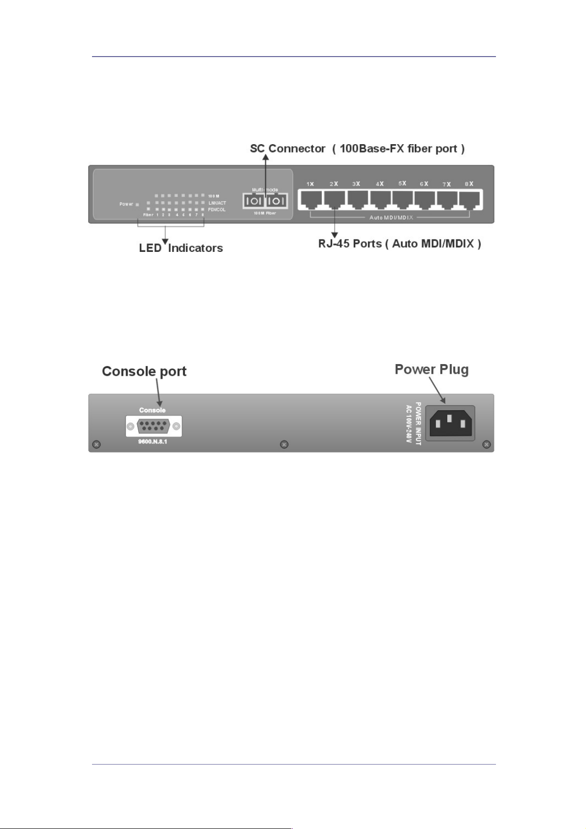
Front Panel
The front panel of the switch has the LED indicators, the fibre
uplink port and the RJ-45 Shielded/Unshielded Ethernet Ports.
Figure 1 - Switch Front Panel
Rear Panel
The rear panel of the switch contains the IEC style power inlet
connector and the console management connector.
Figure 2 –Switch Rear Panel
Ports
RJ-45 Ports. These Ethernet RJ-45 ports support both
shielded and unshielded cabling systems. Each port autonegotiates the 10/100Mbit/s network speed and autodetects the connected device type which eliminates the
need for cross-over cables.
Fibre Port. The switch has a fibre uplink port that can be
connected to 100Base-FX devices. Different optical
connector formats are available (ST/SC/MT-RJ) together
with singlemode and multimode fibres.
Console Port. This port enables the administrator to
change switch settings such as port values, VLANs etc.
AC Power Connector This connector accepts any
standard IEC 320 style power connector.
Tyco Electronics Page 3
Page 4

8 Port Ethernet Smart Switch With Fibre Uplink
Product Models
The following table shows the model numbers of the switches that
are available:-
Product Part Number
Switch with SC multimode connector 0-1591038-x
Switch with ST multimode connectors 0-1591040-x
Switch with MT-RJ multimode connector 0-1591042-x
Switch with SC singlemode connector 0-1591044-x
Table 1 - Product Codes
Where –x is the code for the country. Consult the web site for the
country code table.
Installation
Copper and Fiber Cabling Guidelines
1. The RJ-45 ports can be connected to unshielded twisted pair
(UTP) or shielded twisted pair (STP) cabling systems compliant
with the IEEE 802.3u 100Base TX standard for Category 5. The
cable between the switch and the link partner device (router,
hub, workstation, etc.) must be less than 100 metres long.
2. The switch auto-detects the type of connected device (PC or
hub) and automatically configures the RJ-45 port to avoid the
need for an Ethernet cross-over cable.
3. The fibre link must use either 50 or 62.5/125 micron multi-mode
or 9/125 micron singlemode cable (dependant on model). You
can link two devices over a distance of up to 2km for multimode
or 15km on singlemode. See optical budget specifications.
4. The console port is an RS232 port and should not be used for
cable distances greater than 20 metres. Use the supplied data
cable wherever possible.
Desktop Installation
1. Fit the self-adhesive rubber feet to the underside of the switch.
2. Locate the switch in a clean, flat and safe position that has easy
access to AC power. Ensure that there is sufficient clearance
around the switch to enable air circulation.
Tyco Electronics Page 4
Page 5

8 Port Ethernet Smart Switch With Fibre Uplink
Completing The Installation
When the switch has been installed as specified above, then the
unit can be configured as detailed below:-
1. Connect the AC power cable to the switch. The green Power
LED on the front panel of the switch should light.
2. Connect the Cat. 5/5e twisted pair cables from the network
partner devices to the RJ-45 ports on the switch. When a
network connection is obtained, the green LK/ACT LED
associated with the port will light.
3. Connect the fibre link to the partner device (media converter,
fibre NIC card or fibre switch etc). Verify that the green LK/ACT
LED for the fibre port is lit which indicates that the optical link is
valid.
4. If advanced modes such as port configuration or port-based
VLANs are needed, then use the console port to configure the
switch. See the console port instructions on page 7.
5. If legacy devices that do not support auto-negotiation are
connected to the RJ-45 ports, then it may be necessary to
program the switch to match the speed and duplex modes of
the partner devices. See page 9
6. Note that auto-negotiation can take up to 30 seconds to
complete depending on the partner device.
Tyco Electronics Page 5
Page 6

8 Port Ethernet Smart Switch With Fibre Uplink
LED Indicators
The diagnostic LED indicators located on the front panel of the
switch provide real-time information about switch status. The
following table describes the LED status and meaning.
LED Colour Function
Power Green Power on
10/100
LK/ACT
FDX/COL
LK/ACT
FDX/COL
Green The UTP port is operating at 100Mbit/s
Off
Green Ethernet link pulses are present
Blinks Port transmitting or receiving packets
Off No device is attached or faulty cable
Orange The port is in full-duplex mode
Blinks Collisions in half-duplex mode
Off The port is in half-duplex mode
Green Ethernet fibre pulses are present
Blinks Port transmitting or receiving packets
Off No device is attached or faulty cable
Orange The port is in full-duplex mode
Blinks Collisions in half-duplex mode
Off
The UTP port is operating at 10Mbit/s or
no partner device is attached
The port is in half duplex mode or not
connected correctly
Tyco Electronics Page 6
Page 7

8 Port Ethernet Smart Switch With Fibre Uplink
Configuring The Console Port
The switch has a console port on the rear panel that can be used
to provide simple control and configuration of the unit. The
following port controls are available:-
• Port Data Rate
• Port Duplex Mode
• Port Based VLAN Assignment
A PC can be used to communicate with the switch using the
console port. A terminal emulation program such as Windows
Terminal or HyperTerminal is configured to the following settings:-
• Com Port 1 or 2
• Speed = 9600
• Data Bits = 8
• Parity = None
• Stop Bits = 1
• Flow Control = None
Figure 3 - Console Port Settings
Connect the PC RS232 serial port to the Console port using the
data cable supplied with the switch. Enter any key and the screen
should now show the top-level console display.
Tyco Electronics Page 7
Page 8

8 Port Ethernet Smart Switch With Fibre Uplink
This entry screen is
displayed when the
connection is first
established with the
switch. Select the
required option.
Note that the options
3 and 4 are
immediate and do
not have any
confirmation steps.
Figure 4 - Entry Screen
The port setting
screen is selected
by entering 1 in the
entry menu.
The screen then
shows the current
state of all the
switch ports similar
to the image to the
right.
To change a port
setting, enter the
port number (1..9)
and a new screen is
displayed similar to
Figure 6 on the next
page.
Figure 5 – Port Setting Screen - 1
Tyco Electronics Page 8
Page 9

8 Port Ethernet Smart Switch With Fibre Uplink
This screen enables
the port speed and
duplex mode to be
controlled.
The default is autonegotiation which is
the best method for
most new networks.
However, some
legacy systems may
need to use fixed
duplex and speeds,
so these can be
applied on the switch
using this menu.
Select the option 1..5
to change port
settings or select 6 to
return to the main
menu.
Figure 6 - Port Configuration - 2
Simple port based VLANs can be created by selecting option 2
from the entry menu. There are 2 steps to create VLANs. First
draw a map that shows a matrix of ports and VLANs.
Then select the port
and the required
VLAN ID (1..7). To
Figure 7 - Port VLAN Configuration
add the port to the
VLAN, enter option 1
and then enter option
3 to save the setting.
Repeat this for all
required VLAN and
port combinations.
Note that the switch
resets each time the
VLAN state is viewed.
This is normal.
Figure 8 - VLAN Configuration
Tyco Electronics Page 9
Page 10

8 Port Ethernet Smart Switch With Fibre Uplink
Trouble Shooting
Power
1. Verify that the AC power is present and that the external fusing
is correct and compliant with national requirements. The green
Power LED should be lit to indicate that the switch is powered
correctly.
Data Problems
1. Ensure that the Ethernet partner device (switch, router, NIC etc)
connected to the RJ-45 UTP port of the switch is set for autonegotiation. If this Ethernet partner device does not support
auto-negotiation, then you need to program that device to
operate at 100Mbit/s half duplex or 10Mbit/s half duplex or
program this switch using the console port.
2. If the switch and the partner device cannot auto-negotiate then
both units automatically revert to the lower level of half-duplex
operation. This issue is common to all auto-negotiating Ethernet
devices and the symptoms of incorrect negotiation include data
errors and fragmented packets.
3. Auto-negotiation can take up to 30 seconds to complete
depending on the partner device.
4. Ensure that the switch is not overheating due to obstructed
airflow around the side vents.
5. Select the proper fibre cable for your network. See page 4 for
the supported cable types and installation settings.
6. Ensure that the optical loss budget of the fibre uplink is within
the limits specified on page 11. Note that optical patch cables
and other joints and splices can introduce additional optical
losses that reduce the working distance of the fibre link.
7. Restore factory settings by selecting option 3 on the main menu
of the console port.
Console Problems
1. Verify that the PC has been set up with the correct serial link
settings as detailed on page 7.
2. Ensure that the serial data cable supplied with the switch is
used.
If you still have problems and need further advice, please see
Technical Support section on page 2 to obtain more information.
Tyco Electronics Page 10
Page 11

8 Port Ethernet Smart Switch With Fibre Uplink
Fibre Uplink Port Specifications
The switch has a 100Base-FX optical fibre uplink port that
operates at the 1310nm optical wavelength for both the multimode
and singlemode models.
The fibre size used for multimode links is 50/125 or 62/125 micron.
The fibre size used for singlemode links is 8/125 or 9/125 micron.
The maximum distance between any two fibre optic devices is
determined by a number of factors including optical link loss, the
type and number of patch cords and joints in the link, the launch
power of the transmitter and the sensitivity of the receiver. These
variables make calculating the maximum working distance
between two converters quite difficult and so it is best to design
networks using optical loss budgets rather than using just working
distance.
Plug-In Fiber Ethernet
Module Type
Average
Launch
Power dB
Average
Power
Loss Budget
dBm
Average
Sensitivity
dB
Multimode Converter (SC)
Multimode Converter (ST)
Multimode Converter (MT-RJ)
Singlemode Converter (SC)
Table 2 - Optical Specifications
-18dB
-18dB
-16dB
12dBm -30dB
12dBm -30dB
14dBm -30dB
-18dB 12dBm -30dB
Tyco Electronics Page 11
Page 12

8 Port Ethernet Smart Switch With Fibre Uplink
Product Specifications
Standards
Compliance
IEEE 802.3 10Base-T Ethernet
IEEE 802.3u 100 BASE-TX Fast Ethernet
IEEE 802.3u 100 Base-FX Fast Ethernet
ANSI/IEEE standard 802.3 N-way
Auto-Negotiation
Max Forwarding
Rate
14,880 pps Ethernet port (10Mbit/s)
148,800 pps Fast Ethernet port (100Mbit/s)
Packet Size 64 to 1522 Bytes
LED Indicators Power, Speed, Link Activity, Duplex/Coll.
Ethernet LAN
Network Cable
2-pair UTP/STP Cat. 3, 4, 5 cable EIA/TIA586 100-ohm
Fibre Uplink 100Base-FX using SC, ST or MT-RJ
connectors multimode or SC singlemode
Console 9600bit/s, 1 Stop bit, No Parity, No Flow
Control
MAC Table 4K Addresses
VLANs Up to 7 Port Based VLANs
Switch
1.8Gbit/s
Bandwidth
Dimensions 250mm x 132mm x 37mm (W x D x H)
Mounting
Format
Standalone or rackmount with optional
adapter plates (0-1591068-0)
Weight 1.2Kg
Temperature 0ºC to 45ºC (32ºF to 113ºF) (Operating)
Humidity 10% to 90% (Non-condensing)
Power
IEC 320 Format Main Cord
Connection
Power Supply 100v to 240v AC, 50/60Hz auto-ranging.
Power 21 Watts (Max.)
EMI FCC Class A and CE Mark
Table 3 - Product Specifications
Tyco Electronics Page 12
 Loading...