

Page 1
PGx312
PowerG2-Way Wireless MagneticCont act Device
with Hard-Wired Input Installation Instructions.
Introduction
The PGx312is a two-way wireless PowerG magnetic
contact device. Thedevice has the following features:
l Weatherproof,water-resistant outdoor transceiver
l Flat and curved surface installation
l Battery pull tab for autoenrollment
l Functions atextreme temperatures( -40°C to
66°C / -40°F to151 °F) and is IP66certified
Note:ULtestingtemperatures:-35°C to 66°C
(-31 °F to151 °F)
l Battery life ofup to5 years (with typical
commerical use)
l Integratedmagnetic sensor
l Maximum magnetic gapof 44.5 mm (1.75 in.) on
woodand 31.8 mm (1.25 in.) on metal
l Magnetic sensor toggle if the auxiliary inputonly is
required
l Separatetransmissions from sensor andauxiliary
inputthat trigger thesame RF transmitter.
l Front and back tamper protection( back tamper not
available in USmarket)
l Automatic periodic supervision atr egular intervals
l PowerGtwo-w ay FHSS TDMA technology
l Anti-maskingprotection, based on panel software
version
l Auxiliary hard-wired input, programmable as
either normally open (NO), normally closed (NC),
endof line (EOL, or double end ofli ne (DEOL) for
usew ithadditional device. DEOLfunctionalityi s
based onpanel version software.
l Supports temperature level reports accordingto
PowerGpanel software version
l Paintableusing non-metallic paint. Recommended
paints includeKrylon 'Fusionfor Plastic', RustOleum 'Plastic', and Dupli-Color 'Vinyl & Fabric
Coating'.
Enrolling thePGx312
1. Enter into the installer menuand select 02: ZONES
/ DEVICES.
2. SelectADD N EW DEVICES.
3. Beginthe auto-enrollment process by pulling the
tab,inserting the batteries,or enteringthe device
ID.
4. Selectthe desiredzone number.
5. Configure thelocation,zone type, and chime parameters.
6. Configure thedetector.
Note:
l If the magnetic contactdevice is already enrolled,
configure the magnetic contactdevice parameters
usingthe ModifyD evices option– see step 2.
l To configurethe device parameters, select the
Device Settingsoptionand refer to Configuringthe
Device Parameters.
l To enroll thedevice, power onthe device bypulling
thebattery tab or insert thebatteries. Both methods
will activatethe auto-enrollment process. Alternatively,enter theID:107-XXXX (thenumber of the
deviceprinted on the label).
l If the device was not automatically enrolled, press
theenrollment buttonas seenin Figure 1B.
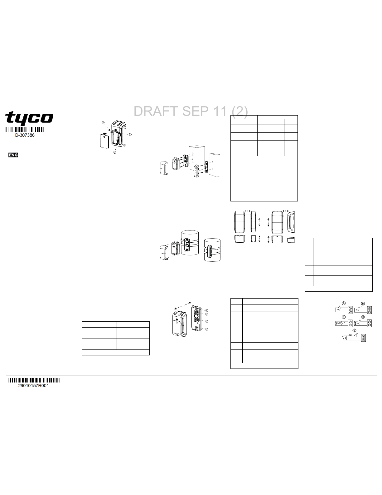
A:Enrollment tab B:Enrollment button
C:Ta mperswitch
Figure 1: Enrollment options
Installation
This equipmentis designed tobe installed byqualified
service persons only. Placethe device abovethe door
or window on the fixed frameand the magnet on the
movablepart ofthe door or window. Do not place the
magnet more than44.5 mm (1.75 in) from the marked
side of thedevice.
To monitor outdoor areas, you can mount the PGx312
ona curved surface,such as afence pole or simil ar.
Note:
l Oncethe battery cover is removed, a tamper mes-
sageis transmittedto thepanel. Subsequent
removal ofthe battery prevents transmissionof the
TAMPER RESTOREalert, leavingthe receiver in
permanent alert. Toavoid this,press thetamper
switch whenyou removethe battery.
l It is recommendedto wait about1 minuteafter bat-
tery removal before insertingthe new batteries.
Caution! Risk of explosion ifthe battery is replacedby
ani ncorrect type. Dispose ofthe used battery according
to the manufacturer’s instructions.
Attention! Some modelshave aback tamper switch
behind the device. As longas thedevice is seatedfir mly
within the bracket, the switchl ever will be pressed
against aspecial break-away bracket segment that is
looselyconnected tothe bracket. Be sureto fasten the
break-away segment tothe wall. Ifthe detector uniti s
forcibly removed from the wall, this segment will break
away from the bracket,causing the tamper switch to
open.
Locald iagnosticst est
A local diagnostic test establishesthe signal strength of
a device ini tscurrent position during the installationprocess. Toperform this mandatory test,complete the following:
1. Separate the decorativecover from thedevice and
unscrew the battery cover. See steps 1to 3 of
Mounting the PGx312.
2. Press thetamper switch onceand release it.
3. Openthe door or window andverify thatdetection
is indicated by a redLED flash.
After two seconds,the LEDflashes three times in
oneof threecolors to indicatethe signal strength.
LEDresponse Reception
Green LEDflashes Strong
Yellow LED flashes Good
Red LEDflashes Poor
No flashes No communication
Table1: LEDreceptionresponse
Important! Reliable receptionmust beassured. There-
fore," poor" signal strengthi snot acceptable. Ifyou
receive a"poor" signal from thedetector, relocate it and
re-test until a "good" or "strong" signalstr engthis
received(i nregions requiring UL-compliant installation,
only “strong” signal strength is permitted).
Note:
l For UL, only strong signal strength is acceptable.
l For detailed diagnostics testinstructions,r efer to
thecontrol panel Installer Guide.
l After this step, reattachthe battery cover.
l The LED lighti soff in normal conditions.
Mounting th ePGx312
Figure 2: Mounting on a flat surface
1. Insert aflat-headscrewdriver into the slotprovided
andpush upward to removethe decorativecover.
2. Unscrew thelower screw from thedevice cover.
3. Separate the device from the bracket.
4. Mark anddril l the required number of holes in the
mounting surface.
5. Screw in the bracket with four screws provided.
6. Reattach thedevice to thebracket.
7. Mountthe magnet base withtwo suppliedscrews
to an adjacent surfaceand attachthe magnetto the
magnet bracket.
Figure 3: Mounting on a curved sur face with straps
To mount the device ona curvedsurface, use straps
(not included)as seen in Figure 3.
Note:
l Use holes A andD i nFigure 4 for standard mount-
ing.Add holes B and C inFigure 4 for tamper protection.
l Align the device and magnetaccordingto thespe-
cificationsin RangeCoverage Directions.
A:Stan dardmo unting
C:Ta mperprot ection
B:Ta mperprot ection
D:Stan dardmo unting
Figure 4: Devic e and bracket separ ation
Range coveragedirections
Non-metallic surface Supports Metallic surface
Open Close Direction Open Close
71 mm
(2.8 in.)
52 mm
(2.0 in.)
X
48 mm
(1.9 in.)
35 mm
(1.4 in.)
40 mm
(1.6 in.)
33 mm
(1.3 in.)
Y (up)
32 mm
(1.3 in.)
25 mm
(1.0 in.)
22 mm
(0.9 in.)
17 mm
(0.7 in.)
Y(down)
17 mm
(0.7 in.)
8 mm
(0.3 in.)
85 mm
(3.3 in.)
55 mm
(2.2 in.)
Z
80 mm
(3.1 in.)
60 mm
(2.4 in.)
Table2 - Range coverage directions
Note:
l The values statedabovem ay vary byup to
10%.For steel installations, the gaps cannot be
less than 3.2 mm (0.1in.).
l For roller shutter assembly, themagnetneedsto
bem ounted 25mm to 35m m (1.0in. to1.4 in.)
from thedevices (onthe Xplane). For all other
installations, ami nimum gapof 5 mm (0.2i n.) is
needed.
l Whenm ountingon asli de door, refer to X. When
mounting on ar oller shutter, refer toY. When
mounting on anormal door, refer toZ .
Parallelmagne t Perpendicularm agnet
Figure 5: Range cove rage directions
Note:
l For UL commercial installations, themaximum
openingto activateis 50.8m m (2i n.).
l Y (up) refers tothe upper half ofthe Y plane.Y
(down) refers to the bottom half of thedevice on
theY plane.
l Whenm ountingthe magnetperpendicular tothe
device,align themagnetwi th the faceof the device
as seen inthe perpendicular magnet image.
Configuring the device parameters
Enter thecontrol panel DEVICE SETTINGSmenu and
follow the configuration instructions for thePGx312magneticcontact device as described in Table 3.
Option Configuration instructions
Magnetic
sensor
Determine whether toenable or disable the
magnetic sensor.
Optional settings :Enable (default) or Dis-
abled.
Input #1
Define the external input according to the
install er's requirements.
Optional settings :Disabled(default), NO,
NC,EOL, or DEOL.
Note:DEOL support is dependent onpanel
software version.
Antimask
Determine whether toenable or disable the
anti-masking.
Optional settings :D isabled (default)or
Enabled(default).
Note: This feature is dependenton panel soft-
warev ersion.
Table3 - Magnetic device parameters
Wiring the auxiliaryinput
Note:
l For UL installations,the device connected tothe ini-
tiatingcir cuit must be locatedi nthe same room as
thetransmitter.
l For UL installations,connectto UL listedres-
idential burglar alarm accessories only.
l For ULC installations,connectU LC listed products
only tothe auxiliary wiring input.
l An alarm messagetransmits oncethe loop is
openedor short circuited.
To connectthis devicew ithanother nearby device by
auxiliary input, completethe followingsteps:
1. Remove the jacket atthe end ofthe cable to
expose the wires within.
2. Perforatethe silicongasket witha 0.8m m
(1/32in.) pin.
3. Pass each wire throughan entry holeand out the
opposite side.
4. Remove the insulationfrom the end of eachwir e.
5. Connect each wire tothe relevant terminal, ref-
erencing Auxiliary Wir ingOptions.
6. Screw theterminal closedusing aflat headscrew-
driver.
Note:
l Use a22 AWG AUX cable (3.0 mm, 0.12 in.jacket
diameter) for this installation.
l Use acable shorter than3 m (10 ft) for theAUX
connection.
l Seal theauxiliary wir ing gasket withR TVSilicone
adhesive sealant.
Auxiliary wiring options
Youcan add more devices tothe circuit of the PGx312
for NC, NO, EOL, or DEOL applications. Each applicationtype is as follows:
NC Excl usiv ely use series connected NCs ensorcon-
tacts if the auxili ary input of the PGx312 is
defined as a normally c losed (NC) type.A nEO L
resistor is not required.
NO Exclusi vely use parallel connected NO sensor
contacts if the auxili ary input of the PGx312 is
defined as NO type. An EOL resis toris not
required.
EOL For EOL supervision, NCor NOsensorc ontacts
can be used. A 5.6kΩEO Lresi stormust be wired
at the farend of the zone loop.
DEOL For DEOL supervision, only N.C. contacts should
be used. A 5.6kΩEO Lresi stormust be wired at
the farend of the zone loop.
Table4:Auxiliary wiringoptions
Note:Figure 6 Eill ustratesa DEOL resistor setupthat
is available dependenton panel software version.
A: N.O. switch
B: N.C. switch
C: EOL ;N.O. switch ;
use5.6 kΩ resistor
D: EOL ;N.C. switch ;
use5.6 kΩ resistor
E: DEOL; N.C. switch
only ;use 5.6kΩ
resistor
Figure 6:Auxi liary wiring options
Calibrating theanti-mask
The anti-mask featureenablesthe detectionof attemptedsabotage, for example, sensor obstruction.
Note:
©2018 Tyco Security Products,Toronto,C anada www.dsc.com
Tech.Support:1-800-387-3630
D-307386 Rev.0 (09/18)
DRAFT SEP 11 (2)
Page 2
l This feature is dependent on panel software ver-
sion.
l Begin theanti-mask calibration process whenthe
deviceand magnetare in thefinal installation position.T his must bethe shortestdistance between
them agnet and the device.
l For theproper operation ofthe AM function, align
them agnet with the sensor decorativecover during
calibration. See Figure5 for parallel andperpendicular magneti nstallation.
Pre-requisites:
l To receivean alert for magnet interference, enable
theanti-masking configuration on the device settingsm enu.
l Completethe anti-masking learning process after
enrollment(see Enrollingthe PGx312) andw iththe
deviceand magneti nthe final installation position.
To enablethe anti-mask feature, completethe following
steps:
1. Positionthe device and magnet pointers to face
eachother withr eference toRange CoverageDi r-
ections.
2. Ensurethe device and magnet are placed nomore
than5 mm apart on the Z plane. SeeRangeC over-
ageDir ections.
Note: During theanti-mask learning process, the
sensor andthe magnet mustbe stable for 10
seconds.
3. Press and hold theenroll buttonfor 6-8 secondsto
start the anti-mask learning process.
Note: Do notrelease the enrollment button while
theyellow LED is lit. Release the buttonafter the
greenLED lightsat 6 secondsand before 8
seconds.
If successful, the greenLED flashesthree times.If
unsuccessful,the redLED flashesthree times.
Note: If thedoor is openwhile the enroll buttonis
pressed, theanti-mask learning process is ignored.
Miscellaneouscomments
DSC wireless systems are very reliableand are tested
to high standards. However, dueto low transmitting
power andl imitedrange (required by FCC andother
regulatory authorities), there are somel imitations tobe
considered as follows:
A. Receivers may beblocked byr adio signals occurring onor near their operatingfrequencies, regardless of
thedigital codeused.
B. A receiver responds only toone transmitted signal at
a time.
C. Wireless devices should betestedr egularly to
determine whether there aresources ofinterferenceand
to protectagainst faults.
Specifications
FrequencyBand (MH z):Europeand rest of world:
433-434,868-869. USA:912-919
MaximumT xPower:
10dBm (10mW)@433MHz
14dBm (25mW) @868MHz
15dBm (30mW) @915MHz
Alarm input:Oneinternal and one auxiliary
Supervision:Signalling at4-mi nutei ntervals
Tamperalert:Report when atamper event occurs
Communication protocol:PowerG
Powersupply: Tyce C
Battery type: 2 x 1.5 VAA Ultimate Lithium Energizer
battery only
Battery life expectancy: 5 years with typical commercial transmissionsper day (not tested by UL)
Low batteryt hreshold: 3.0V
Battery supervision: Automatic transmissionof bat-
tery conditiondata as partof theperiodic status report
andim mediately uponlow battery detection.
Operating Temperature:-40°C to 66°C (- 40°F to
151°F)
Note:UL testingtemperatures: -35°C to 66°C
(-31 °F to151 °F)
Relative Humidity (RH):Averagerelative humidity of
approximately 75% non-condensing. For 30 days per
year relative humidity may vary between85% and 95%
noncondensing.
Note:For UL installations, relative humidity is 93%.
Dimensions(LxW xD): 105 mm x 52 mm x 35mm
(4.1 in. x 2.0 in.x 1.4 in.)
Device weight (including battery): 154 g( 5.4 oz)
Color: Dark grey
UL/ULC notes
TheP G9312has beenlistedby UL for commerciala ndresidentialburglary applicationsand byU LCforre sidentialburglar yapplications in accordance withthe
requirementsin theStandardsUL 634and ULC/ORDC634for Doorand Window
Contact.For UL/ULC installationsuse thisdevic eonly in conjunctionwithcompatibleDSC wireless receivers: HSM2HOST9,HS2LCDRF(P )9,HS2ICNRF(P)
9,PG9920, WS900-19,and WS900-29.
Europe: CE/EN(E N50131-2-6GRA DE2, CLASS IV,
EN50131-6 TypeC) listedPG8312: 868MHz PG4312:433
MHz.According toEN 50131-1,this equipmentcan beapplied in
installedsys temsup toand includingSecu rity Grade2,E nvironmentalClass IV.UK:The PG8312 is suitable for usein systemsinstalledto conformtoPD6 662atGrade 2and
environmentalclass IVB S8243.
SIMPLIFIED EU DECLARATION OF CONFORMITY
Hereby, Tyco SafetyPr oductsCanada Ltddeclares thattheradio equipmenttype
isin compliancewith Directive2014/53/EU .Thefulltextof the EUdeclaration of
conformityis availableatthe followinginterneta ddress:www.dsc.com
PG4312:http://dsc.com/pdf/1808001
PG8312:http://dsc.com/pdf/1808002
Frequency Bands Maximum Power
868.0MHz -868.6 MHz 14dBm (25mW)
868.7MHz -869.2MHz 14dBm (25mW)
433.22MHz -434.64MHz 10dBm (10mW)
European singlepoint ofcontact:Tyco Safety Products,Voltaweg 20,6101 XK
Echt,Netherlands.
FCC COMPLIANCE STATEMENT
WARNING!Changes ormodificationsto this unitnotexpress lyapproved bythe
party responsiblefor compliance couldvoid theuser’s authoritytooper atethe
equipment.
Thisdev icehas beentestedand foundto comply with thelimitsfor aClass B digital
device,p ursuanttoPa rt15of theFCC Rules.These limitsar edesigned to provide
reasonable protectionagainstharmfulinterference inresidential installations.This
equipmentgenerates usesand can radiater adiofrequency energyand, ifnot
installedand usedin accordance withtheinstructions, may causehar mfulinterference tor adio andtelevisionr eception.
However, there isno guaranteethatinterference willnot occur inapar ticular installation.Ifthisdevic edoes causes uchinterference,whic hcan beverifiedb yturning
thedevice offando n,theuser isencour agedtoeliminatetheinterference byone
or more ofthefollowingmeasures:
–R e-orientorr e-locatetherec eivingantenna.
–Incre asethedistance betweenthe deviceand thereceiver .
–C onnectthedevice toan outleton acirc uitdifferentfromthe onethatsupplies
power to ther eceiver.
–C onsultthedealer oran experienced radio/TV technician.
FCCID: F5318PG9312
Innovation Science and Economic Dev elopment Canada
(ISED)Statement
Thisequipmentc omplies withFCC andISE DCanada RFradiationexpo surelimits
setforth for anuncontrolledenv ironment.
Thisdev icecomplies withFCC RulesP art15 andwithISED Canada licenceex emptRSS standard(s). Operation issubject tothe followingtwo conditions:
(1) This devicemay notcause harmfulinterference,and (2)this devicemust
accept anyinterference thatmay bereceiv edor thatmay causeunde siredoperation.
Lepr esentappareiles tconformeaux CNRd 'ISED Canadaapplicab les aux
appareils radioexemptsd elicence.L'ex ploitationestautorisee aux deuxconditionssuiva ntes :(1) l'appareilned oitpas produire debrouillage,et( 2)l'utilisateur
del'appar eildo itacc epter toutbrouillage radioelectriquesubi, memesi lebrouillagees tsusceptibled'en compromettre lefonctionnement.
War ranty
(a) NOWARRA NTY- DSC PROVIDES THESOFTWARE “AS IS” WITHOUT
WARRA NTY. DSCDOE SNOT WARRANTTHA TTHE SOFTWARE WILL
MEET YOURRE QUIREMENTS ORTHAT OPERATIONOF THE
SOFTWAREWILL BEU NINTERRUP TED ORER ROR-FREE.
(b) CHANGES INOPER ATING ENVIRONMENT- DSC shallnotbe responsible
forproblems caused bychanges inthe operatingcharacteristics ofthe
HARDWA RE,or for problemsinthe interaction oftheSOFTWARE PRODUCT
withnon-DS C-SOFTWARE orHAR DWAREP RODUCTS.
(c) LIMITATIONOFLIAB ILITY;WARRA NTYREFLE CTSALLOCA TIONOF
RISK -IN ANYE VENT,IFA NYSTA TUTE IMPLIES WARRANTIES OR
CONDITIONSNOT STATEDIN THISLICENSE AGRE EMENT,DSC’S ENTIRE
LIABILITYUND ERANY PROV ISIONOF THIS LICENSE AGREEMENT
SHALL BE LIMITEDTO THEGREA TEROF THE AMOUNTACTUA LLYP AID
BY YOUTO LICENSE THES OFTWARE PRODUCT ANDFIVE CANADIAN
DOLLARS (CAD$5.00). BECAUSE SOME JURISDICTIONSDO NOTALLOW
THE EXCLUSION ORLIMITATIONOF LIABILITY FORC ONSEQUENTIAL OR
INCIDENTAL DAMAGES,THE ABOV ELIMITATIONMAY NOTA PPLY TO
YOU.
(d) DISCLAIMEROF WARRANTIES -THIS WARRANTY CONTAINSTHE
ENTIRE WARRANTY AND SHALLB EIN LIEU OFANY AND ALLOTHE R
WARRA NTIES, WHETHERE XPRES SEDOR IMPLIED (INCLUDINGALL
IMPLIEDWAR RANTIESOF MERCHANTABILITY ORFITNESS FORA
PARTICULAR PURP OSE) AND OFALL OTHEROB LIGATIONSOR
LIABILITIES ONTHE PART OFDSC. DSCMAK ESN OOTHER
WARRA NTIES. DSCNE ITHER ASSUMES NOR AUTHORIZES ANY OTHER
PERS ONPURP ORTINGTO ACTON ITS BEHALF TOMODIFY ORTO
CHANGE THISWA RRANTY,NOR TOASS UMEFOR ITAN YOTHER
WARRA NTY ORLIABILITY CONCERNINGTHIS SOFTWAREP RODUCT.
(e) EXCLUSIVE REMEDY AND LIMITATIONOFWA RRANTY- UNDER NO
CIRCUMSTANCES SHA LLDSC BE LIABLE FOR ANYS PECIAL,
INCIDENTAL,CONS EQUENTIALOR INDIRECTDA MAGES BAS EDUP ON
BREA CHOF WARRANTY,B REACH OFCONTRACT,NE GLIGENCE,
STRICTLIAB ILITY,OR ANYOTHE RLEGAL THEORY.S UCHDA MAGES
INCLUDE,B UTARE NOTLIMITEDTO,LOS SOFP ROFITS,LOSS OFTHE
SOFTWARE PRODUCT ORANY ASS OCIATED EQUIPMENT,COST OF
CAPITAL, COSTOFS UBSTITUTEOR REPLACE MENT EQUIPMENT,
FACILITIES ORS ERVICES, DOWNTIME,PURCHA SERS TIME,THE
CLAIMS OFTHIRD PARTIES, INCLUDINGC USTOMERS ,AND INJURY TO
PROPE RTY.WARNING:
DSC recommendsthatthe entire systembe completelytested ona regularbasis.
However, despitefrequenttesting,and dueto,butnot limitedto,criminaltampering
or electrical disruption,itispo ssibleforthis SOFTWARE PRODUCTto failto performas expected.The termIC before the radiocertificationnumbers ignifiesthat the
IndustryC anadatechnicals pecifications weremet.ThisC lass B digitalapparatus
complieswith CanadianICES- 003.Thisdevice complieswith RSS-247 of
IndustryC anada.Operationis subjecttothe followingtwo conditions:(1) this
device maynotc auseinterference,and (2)this device mustac ceptany interference,including interference thatmaycaus eundesired operationofthe device.
Cetappareil numériquede laclasse Bes tconformeà lanormeN MB- 003du
Canada.Ce dispositifsatisfaitaux exigences d’IndustrieCanada, prescrites dans
ledoc umentCNR- 247.sonutilisationes tautoriséeseulementaux conditions
suivantes:( 1)ilne doitpas produirede brouillageet( 2)l’utilisateur dudispositifdoit
êtreprêt àacce pter toutbrouillage radioélectriquereçu, mêmesi cebr ouillagees t
susceptible decompromettrele fonctionnementdudis positif.
©2018 Tyco Security Products,Toronto,C anada www.dsc.com
Tech.Support:1-800-387-3630
D-307386 Rev.0 (09/18)
DRAFT SEP 11 (2)
 Loading...