

Page 1
© 2010 Tyco Safety Products PAGE 1 of 7
M600 SERIES
01B-04-D12
55/10
Registered Company: Thorn Security Ltd. Registered Office: Dunhams Lane Letchworth Garden City Hertfordshire SG6 1BE
EQUIPMENT:
PUBLICATION:
ISSUE No. & DATE:
MR601TEx INTRINSICALLY SAFE ENHANCED OPTICAL SMOKE DETECTOR
PRODUCT APPLICATION AND DESIGN INFORMATION
1. INTRODUCTION
The MR601TEx Intrinsically Safe High Performance Optical
Smoke Detector forms part of the M600Ex series of plug in
detectors for ceiling mounting. The detector plugs into the
5BEx 5” Universal IS Base and is intended for two-wire
operation on the majority of the control equipment currently
manufactured by the company. The Intrinsically Safe High
Performance Optical detector is available in one sensitivity
setting only.
2. INTRINSIC SAFETY
The detectors are for use in potentially explosive gas and dust
atmospheres (zone 0 gas, zone 20 dust).
The detectors are designed to comply with EN/IEC 600790:2006, EN/IEC 60079-11:2007 and EN/IEC61241-11:2006 for
Intrinsically Safe apparatus. They are certified:
ATEX code:
II 1 GD
Certificate: BAS01ATEX1134X
Gas/Dust code: Ex ia IIC T5
Ex iaD 20 T100°C
IECEx Certificate: IECEx BAS 07.0056X
These detectors are designed and manufactured to protect
against other hazards as defined in paragraph 1.2.7 of Annex II
of the ATEX Directive 94/9/EC.
2.1 DETECTOR USE
It is recommended that the detector is used in conjunction with
a suitable isolator or shunt diode safety barrier in a certified
Intrinsically Safe system, ie, System 620.
2.2 SPECIAL CONDITIONS OF SAFE USE
The apparatus has a plastic enclosure which constitutes a
potential electrostatic hazard. The enclosure must be cleaned
only with a damp cloth.
3. OPERATING PRINCIPLE
The MR601TEx operates by sensing the optical scatter from
smoke particles generated in a fire. While the optical scatter
detector can give good detection performance for the majority
of fires, some fast burning fires produce little visible smoke and
some produce very black smoke, neither of which are easily
detected by the optical scatter detector. (Such fires are
represented in EN54-7 by Polyurethane and Heptane type fires
respectively). These fires do, however, produce high heat
outputs with an associated rise in air temperature.
The detector has been designed to offer improved detection of
such fires, by detecting the rapid rate-of-rise of air temperature
and under these conditions, increasing the smoke detection
sensitivity. This gives an earlier detection of such fires and a
broader detection capability than a standard detector.
The MR601TEx detector has two sensing systems as follows:
• An optical chamber with associated electronics
to measure the presence of smoke by light
scatter.
• A thermistor with its associated electronics to
detect the presence of hot air draughts or high
temperatures.
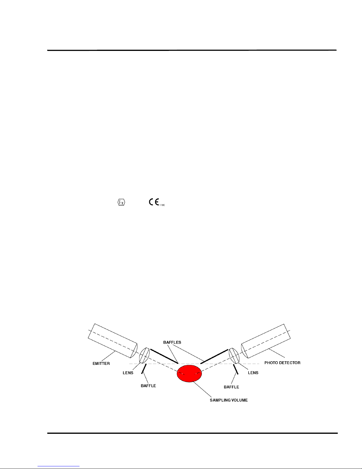
Fig. 1 Optical System Schematic
Page 2

M600 SERIES
01B-04-D12
55/10
PAG E 2 o f 7
SMOKE
PATH
SAMPLING
VOLUME
FINS
Fig. 2 Measuring Chamber Showing Smoke Flow Path
3.1 OPTICAL SYSTEM
The MR601TEx detects visible particles produced in fires
by using the light scattering properties of the particles. The
detector uses the optical arrangement shown
diagrammatically in Fig. 1.
The optical system consists of an infra-red emitter and
receiver, with a lens in front of each, so arranged that their
optical axes cross in the sampling volume. The emitter,
with its lens, produces a narrow beam of light which is
prevented from reaching the receiver by the baffles. When
smoke is present in the sampling volume a proportion of the
light is scattered, some of which reaches the receiver. For a
given type of smoke, the light reaching the photodetector is
proportional to the smoke density. The amplified output
from the sensor can be used to activate an alarm circuit at a
predetermined threshold.
FINS
REFERENCE
SENSING
Fig. 3 Thermal Measuring System
Page 3
M600 SERIES
01B-04-D12
55/10
© 2010 Tyco Safety Products PAGE 3 of 7
Registered Company: Thorn Security Ltd. Registered Office: Dunhams Lane Letchworth Garden City Hertfordshire SG6 1BE
EQUIPMENT:
PUBLICATION:
ISSUE No. & DATE:
STATUS
LED
IR
EMITTER
PHOTO
DIODE
SENSOR
AMPLIFIER
GAIN
TIMER/
OSCILLATOR
SYNCHRONOUS
DETECTOR
COMPARATOR
REF
SENSING
THERMISTOR
REFERENCE
THERMISTOR
1
2
COMPARATOR
THRESHOLD
LED
OUTPUT
SWITCH
COUNTER
LINE A IN
LINE A OUT
LINE B IN/OUT
BRIDGE
BASE
R
L1
L2
L
REMOTE LED
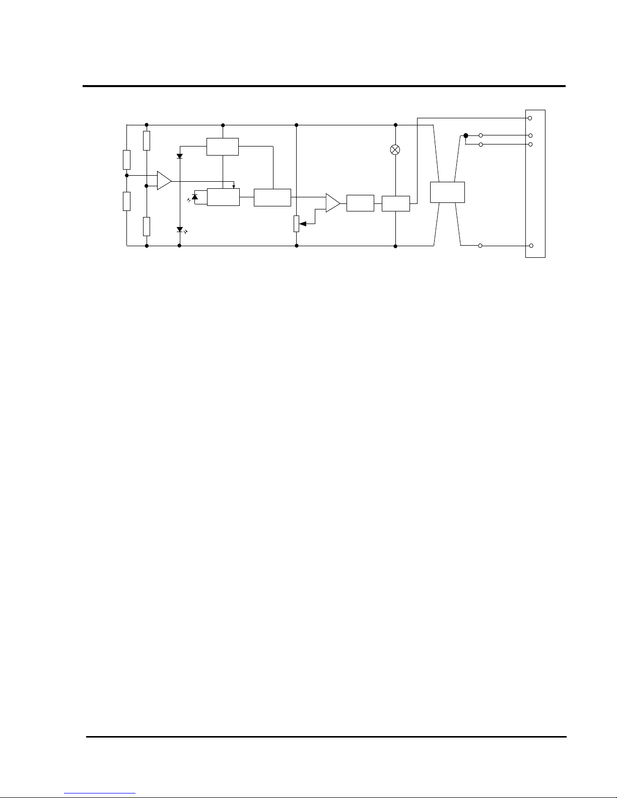
Fig. 4 Block Schematic of Detector
3.2 FEATURES OF MEASURING CHAMBER
The MR601TEx uses vertical chevrons to exclude ambient
light.
Smoke incident on the detector is channelled into the
detector by the outer cover fins (Fig. 2) and passes through
the vertical chevrons. The smoke is deflected into the
optical chamber and through the sampling volume before
passing out the other side of the detector.
The emitter (Fig. 1) is a GaAlAs solid state type operating
in the near infra-red (880nm peak), while the detector is a
matched silicon photodiode. These devices, together with
their associated lenses, are held in place by the chamber
mouldings. The design of the optical system is such that the
presence of small insects such as thrips, should not cause
false alarms.
3.3 THERMAL MEASURING SYSTEM
Refer to Fig. 3.
This is designed to detect the presence of horizontally
moving hot air draughts moving across the ceiling which
occur in a fast burning fire.
The measuring system consists of two fast responding
negative temperature thermistors. A sensing thermistor is
located above the labyrinth under the cover in the airstream
and will detect any sudden changes in the air temperature or
draughts of hot air moving across the ceiling. The second
thermistor is located out of the airflow within the smoke
labyrinth and has a longer time constant and is used as a
temperature reference to compare the sensing thermistor
against. At a given temperature differential between the
two thermistors, the comparator will switch and increase the
gain of the amplifier, thereby increasing the sensitivity of
the sensor. Fins located on the top of the labyrinth are
designed to increase air turbulence and the efficiency of the
sensing thermistor.
3.4 CIRCUIT OPERATIONS
A simplified block schematic of the detector is given in
Fig. 4.
The emitter is subjected to a pulse stream only every 10s in
order to reduce the quiescent current. The pulse signal
received by the photodiode is fed to a high-gain
amplifier. If smoke is present, the pulse signal received
varies in proportion to the smoke density.
The amplifier output is fed via an integrator, the output of
which is compared to a preset threshold
level. Sophisticated synchronous detection techniques are
used to reduce the effects of noise and spurious transients.
The gain of the front end amplifier is controlled by the
thermistor bridge circuit. When the temperature differential
between the two thermistors exceeds a certain value, the
amplifier gain increases. Under these conditions the High
Performance Optical detector is more sensitive to the
presence of smoke and is said to be in ‘Enhanced Mode’.
When the detector is in the ‘Enhanced Mode’, the detector
will only alarm if a smoke signal is present. The presence
of rising temperature alone cannot cause an alarm.
If the signal amplitude exceeds a threshold level, then the
emitter samples the smoke every two seconds. The sample
period remains at two seconds if the signal is above the
threshold. When the counter has counted three consecutive
pulses above the threshold, the output stage is latched into
the alarm condition. If however, the amplitude of the
second or third pulse is below the threshold, then the pulse
period reverts to 10 seconds and the counter resets. The
switching of the output stage lights the alarm LED and
provides drive for the remote LED indicator.
The critical front end of the circuit is run off a 12V regulator
to make it independent of supply voltage.
The detector is polarity conscious.
Page 4

M600 SERIES
01B-04-D12
55/10
PAG E 4 o f 7
Fig. 5 Overall Dimensions of MR601TEx
43
109
3.5 WIRING
Loop cabling is connected to base terminals as follows:
L-VE
L1 +VE IN
L2 +VE OUT
R Remote LED Drive
4. MECHANICAL CONSTRUCTION
The major components of the detector are:
• Body Assembly
• Printed Circuit
• Optical Chamber
• Optical Chamber Cover
• Thermistor
• Light Pipe
• Outer Cover
4.1 ASSEMBLY
The body assembly consists of a plastic moulding which has
four embedded detector contacts which align with contacts
in the 5BEx base. The moulding incorporates securing
features to retain the detector in the base.
The PCB is soldered to the body contacts. These contacts
act as a mechanical fixture during assembly and provide
electrical contact between the contacts and the PCB. The
PCB is then potted.
The chamber cover is clipped to the body over the optical
chamber ensuring the thermistor protrudes through the
cover. The light pipe is slotted into the chamber
cover. Finally, the outer cover is clipped to the body.
4.2 TEST AND FINAL ASSEMBLY
The detectors are fully functionally tested and their
sensitivities set in a smoke tunnel to ensure correct
calibration. The sealing ring and labels are then fitted to
complete detector assembly.
5. TECHNICAL SPECIFICATION
5.1 MECHANICAL
Dimensions
The dimensions of the MR601TEx detector are shown in
Fig. 5.
Materials
Body and cover: FR110 ‘BAYBLEND’
Fire Resistant
Fig. 6 MR601TEx Enhanced Optical Smoke Detector
with 5BEx 5” Base
Page 5

M600 SERIES
01B-04-D12
55/10
© 2010 Tyco Safety Products PAGE 5 of 7
Registered Company: Thorn Security Ltd. Registered Office: Dunhams Lane Letchworth Garden City Hertfordshire SG6 1BE
EQUIPMENT:
PUBLICATION:
ISSUE No. & DATE:
0
5
10
15
20
25
30
35
0 2 4 6 8 10 12 14 16 18
Detector Voltage (V)
Detecor Current [mA]
Fig. 7 Alarm Load Presented to the Controller
Wei ght
Detector: 0.128kg
Detector + base: 0.174kg
5.2 ENVIRONMENTAL
Operating Temperature: -20oC to +70oC
(please see note below).
Storage Temperature: -25
o
C to +80oC
Note:
1) The operating temperatures quoted exceed
the ATEX Certification limits.
2) Operation below 0
o
C is not recommended
unless steps are taken to eliminate
condensation and hence ice formation on the
detector.
Relative Humidity: 95% non-condensing
Shock: )
Vibration: )
Impact: ) To EN54-7
Corrosion: )
5.3 ELECTROMAGNETIC COMPATIBILITY
The detector complies with the following:
Product family standard EN50130-4 in respect of
Conducted Disturbances, Radiated Immunity,
Electrostatic Discharge, Fast Transients and Slow High
Energy
EN 61000-6-3 for Emissions
5.4 ELECTRICAL CHARACTERISTICS
The alarm load presented to the controller is shown in Fig. 7.
The following characteristics shown in Table 1 are taken at
25
o
C with a supply voltage of 20V unless otherwise
specified.
Intrinsic Safety Rating:
Maximum Voltage for safety (U
i
): 28V
Maximum Current for Safety (I
i
): 93mA
Maximum Power Input (P
i
): 650mW
Equivalent Inductance (L
i
): 0
Equivalent Capacitance (C
i
): 0
5.5 PERFORMANCE CHARACTERISTICS
The fundamental parameter used to define the sensitivity of
an optical smoke detector is the level of smoke which will
just produce an alarm under ‘ideal’ conditions. This
parameter, known as the response threshold value, is
normally measured in a smoke tunnel and is defined in
terms of the obscuration produced by the smoke over a one
metre path. The response threshold value is normally given
in dB/m, (or % per m).
Characteristics Min. Typ. Max. Unit
Operating Voltage (d.c.) 16 20 28 V
Average Quiescent Current 90 110 μA
Switch-on-Surge 130 μA
Stabilisation Time 60 sec
Alarm Current See Fig. 6 mA
Holding Voltage 5 V
Holding Current 1 mA
Reset Time 2 5 sec
Remote LED Drive Remote LED via 3.4k
Table. 1 Electrical Characteristics
Page 6

M600 SERIES
01B-04-D12
55/10
PAG E 6 o f 7
Interpretation of response threshold value is somewhat
complicated by the fact that the measurement is given in
terms of obscuration, whereas the detector works by
scattering from the smoke particles. The response threshold
(m) value will therefore, depend on the colour of the
smoke. Black smokes give less scattering than light smokes
for given values of obscuration as shown in Fig. 8.
Sensitivities are invariably specified for ‘grey’ smokes as
produced by typical smouldering fires. Values for the
MR601TEx are given below.
5.5.1 RESPONSE TO RATE OF CHANGE
OF TEMPERATURE
The detector will not be enhanced by slow rates of change of
temperature, or by cold air draughts moving across the
ceiling creating negative rates of change of
temperature. The detector is designed to detect sudden
horizontal draughts of hot air produced by fast burning
fires. The enhancement switching point has been set to
allow the detection of TF1 type fires.
Normal response threshold = 0.19 dB/m, 2.7%/m typical.
Enhanced mode threshold = 0.08 dB/m, 1.1%/m typical.
5.6 RESPONSE TO FIRE TESTS
The response of an optical scatter detector to a fire will
depend to a large extent on the colour of the smoke produced
in the fire. However, other factors such as the detector
smoke entry characteristics, the development of the fire and
the thermal lift produced by the fire are important. In order
to evaluate the response under realistic conditions, detectors
are subjected to test fires which cover a range of fire
types. These tests are defined in EN54 Pt 7. The
MR601TEx passes the following Fire Tests:
Fig. 8 Response Threshold vs Smoke Colour
Note: TF2 to TF5 are mandatory test fires required to
meet EN54 Pt 7.
The MR601TEx is designed to respond to the mandatory
tests TF2 to TF5 as required by BS5445 Pt 7. The
MR601TEx gives an earlier response to TF5 fires than the
MR601 due to its thermal circuit detecting the heat
generated by this test of fire and the MR601TEx being
‘enhanced’. For the same reason the MR601TEx will
detect test fire TF1 (open wood cellulosic flaming fire)
which is not normally detected by optical smoke detectors demonstrating the detectors broader detection capability.
The MR601TEx does not respond to TF6 liquid
(methylated spirit) which although having a rapidly rising
temperature, does not generate any optical scattering. This
shows that the High Performance Optical detector will not
respond to hot air draughts without the presence of smoke.
6. INSTALLATION
RECOMMENDATIONS
It is not recommended that the MR601TEx be installed in
areas where it is likely to be regularly enhanced, since in
this condition the detector is extra sensitive and there is a
possibility of unwanted alarms from low ambient smoke
levels.
The MR601TEx is designed to become enhanced by
detecting a rapid temperature rise (>10°C) in air moving
horizontally across the ceiling. Siting sensors in positions
where air is being blown through the detector should
therefore, be particularly avoided, eg, close to ceiling ducts
or ceiling mounted industrial heaters; or areas of forced
ventilation, such as ducts and under floor voids of computer
suites.
Also, not recommended are areas open to the outdoors, such
as cargo handling bays, or areas where the detector may
become contaminated.
The MR601TEx is not recommended for use in applications
where a heater jacket is required.
The MR601TEx is primarily aimed at benign
environments.
TF1 open cellulosic (wood-flaming)
TF2 smouldering pyrolysis
TF3 glowing smouldering (cotton)
TF4 open plastics (polyurethane foam)
TF5 liquid (n-heptane)
Table 2: Response to Fire Tests
Page 7

M600 SERIES
01B-04-D12
55/10
© 2010 Tyco Safety Products PAGE 7 of 7
Registered Company: Thorn Security Ltd. Registered Office: Dunhams Lane Letchworth Garden City Hertfordshire SG6 1BE
EQUIPMENT:
PUBLICATION:
ISSUE No. & DATE:
7. CPD INFORMATION
8. DETECTOR IDENTIFICATION
The detector is identified by the logo label, as shown in
Fig. 9.
0832
Tyco Safety Products
Dunhams Lane
Letchworth SG6 1BE
UK
0832-CPD-0248
MR601TEx
Application & Design 01B-04-D12
Installation Instructions 01B-04-I3
Service Instructions 01B-04-S2
06
EN 54-7: 2000 + A1: 2002
Conventional Intrinsically Safe high
performance photoelectric smoke detector
with heat enhancement for use in fire
detection and alarm systems in buildings
tyco
Fig. 9 Detector identification
GREEN
9. ORDERING INFORMATION
MR601TEx Intrinsically Safe
Enhanced Optical Smoke Detector: 516.054.011.Y
5BEx 5” Universal IS Base: 517.050.023
JM/jm
5
th
May 2010
 Loading...