

Page 1
MP-902 PG2
Wireless outdoor curtain PIR detector with anti-masking and pet immunity
1. Overview
The MP-902 PG2 is a smart, wireless outdoor curtain PIR detector with
anti-masking. It is suppor ted by the PowerMaster alarm system and uses
PowerG two-way communication protocol.
The detector has the following features:
l
Two channel Pyro ( patented) thermal sensor output
l
Microprocessor-controlled temperature compensation
l
White light protection
l
Adjustable pet immunity selector with three options: no pet, a small pet
weighing less than 3 kg or 6.6 lb, or a pet weighing less than 18 kg
or 40 lb.
l
Adjustable detection sensitivity
l
Parabolic and elliptical optics (patented)
l
Target Specific Imaging™ (TSI) technology distinguishes between
humans and pets weighing up to 18 kg or 40 lbs
l
True Motion Recognition™ algorithm (patented) distinguishes
between the tr ue motion of an intruder and any other disturbances
which may cause false alarms.
l
Cross-direction detection: both directions, left to right, and right to left.
l
Active smart anti-masking ability recognizes spray and dust (patented)
l
No vertical adjustment is needed.
l
Long-life battery which is due to the ultralow current consumption
l
Front and back tamper protection (patented)
l
Supports temperature and light level reports according to the PowerG
panel version
Note:For UL installations, onlyuse the device with UL listed control units.
2. Installation advice
Installation instructions
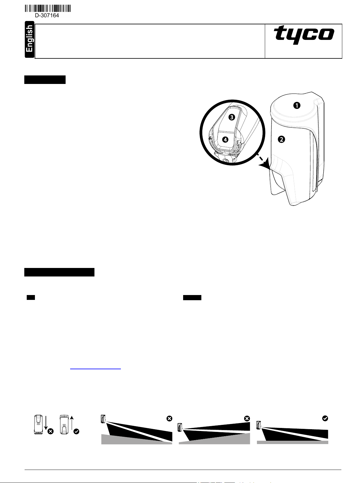
Figure 1: MP-902 PG2
1. Bracket
2. Detector
3. Indication LED
4. PIR opticalwindow
Qualified service persons onlycan install the MP-902 PG2. Before you install the device, consider the following points:
Do:
l Installthe MP-902 PG2 according to the Standard for Installation and
Classification of Burglar and Holdup Alarm Systems,UL 681.
l Mount the detector so that the expected movement of the intruder will
cross the PIR beam.
l Mount the device on a vertical surface and as straight as possible.
l Mount the device upright. See Figure 2.
l Direct the detector at a stable surface, such as a wall or fence, to
provide a curtain detection boundary for better detection.
l Mount the device at a height that agrees with your pet immunity
preference. See Setting the pet immunity for more information.
l Consider weather conditions that can trigger false alarms, suchas
Do not:
l Installthe device over sloped ground. See Figure 3.
l Installthe device close to tree branches as weather conditions can
cause movement, resulting in false alarms
l Installthe device in hazardous locations
l Installthe device in areas with a pollution degree higher than pollution
degree 2
l Installthe device in circuits above overvoltages category II
l Obscure the field of view of the detector
l Co-locate or operate the antennas used for this product in conjunction
with any other antenna or tr ansmitter
l Mount the device on surfaces where surface vibration can occur
moving tree branches or leaves, and other related environmental
conditions
l Locate the device at least 20 cm from all per sons during normal
operation to comply with FCC and ISED Canada RF exposure
compliance requirements
Figure 2:
Mounting orientation
Figure 3: Flat grou nd installation
D-307164 MP-902 PG2 Installation instructions 1
Page 2
Notes:
l PIR beams can extend past the set range coverage distance if you direct the detector at an open space.
l To calibrate the detector sensitivity to identify persons more accurately, set the detector detection range. For more information, see Configuring the
detector parameters .
l To protect a window, mount the detector on an upper corner of the window frame so that the PIR beams ar e parallelwith the glasspane.
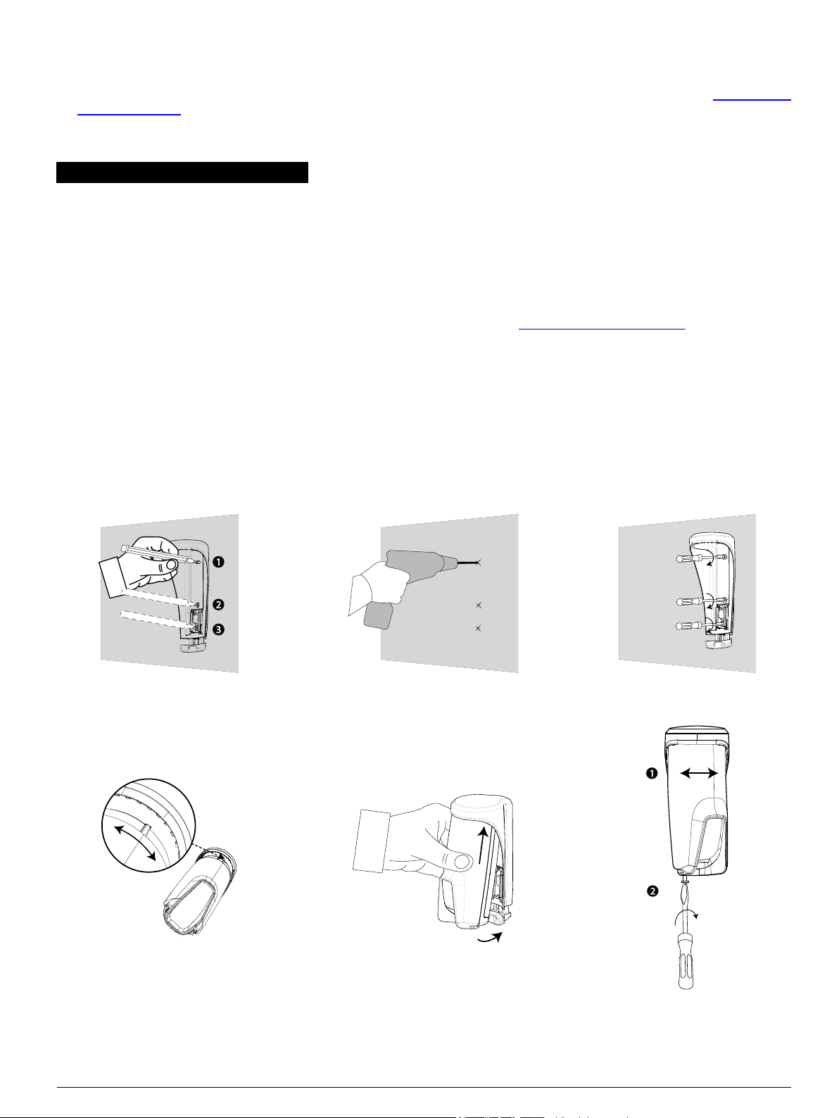
3. Mounting the MP-902 PG2
To mount the MP-902 PG2, complete the following steps:
1. Use the uppermost and middle holes in the device bracket to mark two holes in the mounting surface. See Hole Number 1 and Hole Number 2 in
Figure 4.
2. Optional:To availof tamper protection, use the bottommost hole in the break-away segment of the bracket to mark a third hole in the mounting
surface. See Hole Number 3 in Figure 4.
3. Drillthe required holes in the mounting surface according to the markings and insert the wall plugs. See Figure 5.
4. Fasten the bracket to the mounting surface with screws. See Figure 6.
5. Insert the batteries into the detector and close the battery cover. For more information, see Inserting or replacing the batteries.
6. Insert the top of the detector into the bracket. As you insert the detector, choose a slot in the bracket that positions the detector to cover the area
that requires protection. See Figure 7 and Figure 8.
Note:When you complete Step 6, a blinking LED indicates the start of the tamper self-calibrating procedure.
Note: When the detector is resting on the unscrewed bracket, it can be rotated freely to a more exact final position. See Hole Number 1 in Figure
9.
7. While the LED is blinking, tighten the bottom screw to close the bracket. See number 2 in Figure 9.
Note: If the yellow LED stops blinking before the screw is tightened adequately, remove the detector from the bracket and wait three seconds.
Repeat Step 6 to start the self-calibrating procedure.
Figure 4:
Marking the screw holes
Figure 7:
Figure 8: Slotting into the device
Figure 5:
Drilling the screw holes
Figure 6:
Fastening the bracket
Rotatio n slot
Figure 9:
Closing the bracket
D-307164 MP-902 PG2 Installation instructions 2
Page 3
4. Enrolling the MP-902 PG2
To enroll the MP-902 PG2, from the Installer menu, select 02:ZONES/DEVICES, and complete the steps in the following procedure:
Notes:
l Use only in conjunction with UL/ULC listed control panels for UL/ULC listed installations.
l If you enr oll the MP-902 PG2 in PowerMaster panels with version 19.4 or lower, the detector enrollsas an outdoor PIR motion detector. The device
enrolls in the panel with the device ID, 130-xxxx, and the name, Motion Outd. .
1. From the installation menu, click02:ZONES/DEVICES.
2. Select ADD NEW DEVICES.
3. When the panel displaysENROLL NOW or ENTER ID:xxx-xxxx, enroll the device with one of the following methods: pullthe enrollment tab or
insert the batteries to power on the device and start the auto-enrollment pr ocess.
Note:If the device does not automatically enroll, press the enrollment button or enter the device ID:xxx- xxxx in the panel. The device ID is
printed on the label.
4. To change the device number, click the arrow button or type the zone number.
5. To configure the location, zone type and chime parameter s, select Z0x.LOCATION, Z0x.ZONE TYPE, and Z0x.SET CHIME, and set the
configurations you require.
6. From the MODIFY DEVICES menu, select PARTIT IONS.
7. Enter the partition numbers you want to assign the device to with the keypad.
Note: You can assign a single partition, or multiple partitions.
Notes:
l After you enroll the detector, you can configure the detector parameter s and assign partitions. See Configuring the detector parameters for more
information.
l PARTITIONS appears only if the panel supports partitioning and the feature was enabled prior to this pr ocedure. For more information, refer to
Partitioning in the PowerMasterinstallation guide.
5. Configuring the detector parameters
5.1. Modifying the MP-902 PG2
To modify the MP-902 PG2, enter the DEVICE SETTINGS menu and follow the configuration instructions as described in Table 2.
Table 2: Modifying the d evice
Option Con fig urin g instructions
Alarm LED Activate or deactivate the alarm LED indication.
PIR range Select one of the three ranges, according to your installation preference.
Outdoor anti-mask Enable or disable the outdoor anti-masking feature.
Alarm hours Set the motion detector to alarm always or onlywhen it isdark.
Alarm direction
VERY HOT
> 35°C
(>95°F)
Optional settings: LED ON (default) and LED OFF.
See Setting the detector range.
Optional settings: Disabled (default) and Enab led.
Note:For UL/ULC installation, only use the alarm hours feature for night protection as a supplement to the protection
already covering the area.
Optional settings: Day and night (default) and Nig ht only.
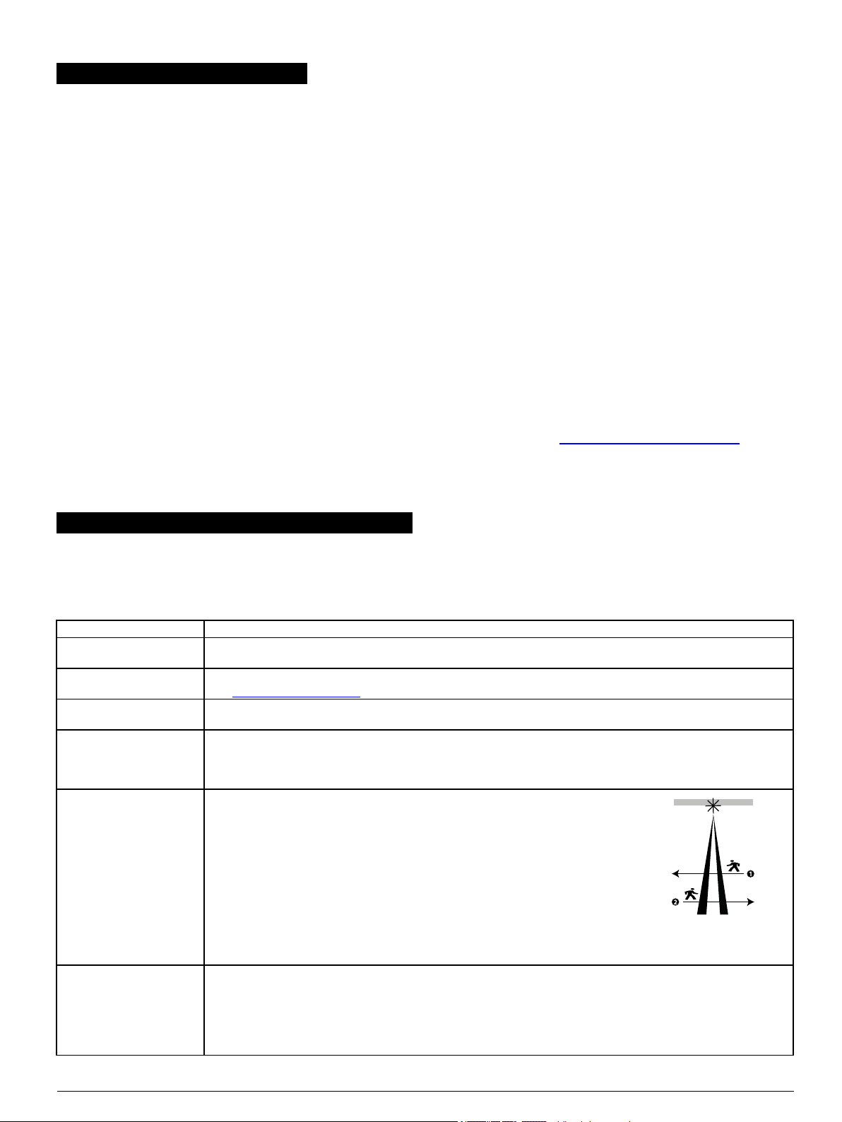
Define the detection direction.
The alarm direction function can reduce the probability of false alarms by mor e than
half when the detector is pr otecting a door or a gate. With this function, the device can
differentiate between property inhabitants exiting, and potential intruders entering the
premises.
Note:T his feature is onlyavailablein PowerMaster panels version 20.2 and higher.
Optional settings: Both (default), Left to right, Right to left.
See Figure 10 for the alarm direction diagram. In Figure 10, Number 1 shows a Right
to left detection pattern and Number 2 shows a Left to right detection pattern. The
right and left directionsrefer to the point of view of the installer while observing the
Figure 10: Direction
detector in itsfixed position.
Define whether or not the control panel reports a VERYHOT alert when the temperatur e rises above the threshold
value for at least the duration of time specified in the alert delay value. The alert restore occurs when the temperatur e
drops 1°C or 1.8°F below threshold for at least the dur ation of the restore delay value.
Note: The default thresh old value for VERYHOT is 35°C or 95°F. The default alert delay value and the default
restore delay value is 10 minutes.
Optional settings: See Table 3.
detection
D-307164 MP-902 PG2 Installation instructions 3
Page 4

COLD
< 19°C
(<66°F)*
Define whether or not the control panel reports a COLD alert when the temperature drops below the thresh old value
for at least the duration specified in the alert delay value. The alert restore occurs when the temperature rises1°C or
1.8°F above the thresh old value for at least the duration of the restore delay value.
Note: The default thresh old value for COLD is 19°C or 66°F. The default alert delay value and default restore
delay value is10 minutes.
Optional settings: See Table 3.
FREEZING
< 7°C
(<45°F)*
Define whether or not the control panel reports a FREEZING alert when the temper ature drops below the thresh old
value for at least the duration specified in the alert delay value. The alert restore occurs when the temperature rises
1°C or 1.8°F above the threshold value for at least the duration of the restore delay value.
Note: The default thresh old value for FREEZING is 7°C or 45°F. The default alert delay value and default restore
delay value is10 minutes.
Optional settings: See Table 3.
Disarm activity Define the length of time that the sensor continuesto detect motion during the disarm process.
Optional settings: NOT Active (default), YES – no delay, YES + 5 s delay, YES + 15 s delay, YES + 30 s delay,
YES + 1 min , YES + 2 min , YES + 5 min , YES + 10 min, YES + 20 min, YES + 60 min
Notes:
l To generate an alarm or restore transmission, the temperature must pass beyond the threshold value for the required duration.
l The user can give access to the installer to remotely enable or disable the indication LED.
5.2. Configuring the temperature alerts
Configure each of the four temperature alerts: VERY HOT, COLD, FREEZING, and FREEZER. Table 3 describes the temperature configuration
setting options.
Table 3: T emperature configu ration settings
Option Con fig urin g instructions
Threshold Displays the last saved th reshold value. To change the default value, clickthe back or next button to decrease or increase the value
and clickOK.
Disable
/Enable
Alert delay Define the amount of time to passbefore an alert isrepor ted when the temperature exceedsthe defined default duration.
Resto re
delay
Defines whether or not the panel willreport an alert or not.
The alert delay time values are:
Immediately, 1 min, 2 min, 10 min, 15 min, 20 min, 30 min
Defines the amount of time to pass before a restoration alert is reported when the temperature returns below the threshold value.
The resto re delay time valuesare:
Immediately, 1 min, 2 min, 10 min, 15 min, 20 min, 30 min
5.3. Setting the detector range
From the PowerMaster panel installer menu, select 02:ZONES/DEVICES and follow the menu path displayed in Table 4 to configure the device
detection range.
Note:If you enroll the MP-902 PG2 in PowerMaster panels with version 19.4 or lower, the detector enrollsas an outdoor PIR motion detector. The
device enrolls in the panel with the device ID, 130-xxxx, and the name, Motion Outd. .
Table 4: Set tin g the detector range
Panel Device type Menu path and option s Rang e
V20.2 and higher MP-902 PG2
S.OutCurtain
ID: 129-xxxx
V19.4 and lower TOWER-20AM
Motion Outd.
ID: 130-xxxx
Notes:
The range refers to Number 2 in Figure 11.
The symbolsignifies the detector point of view and the beginning of the PIR curtain.
>02:ZONES/ DEVICES>
>DEVICE SETTINGS>
>PIR RANGE>
Long
Medium
Short
>02:ZONES/DEVICES>
>DEVICE SETTINGS>
>PIR SENSITIVITY>
High
Low
One region
8 m
5 m
3 m
8 m
3 m
8 m
D-307164 MP-902 PG2 Installation instructions 4
Page 5

1. 2 m (6.56 ft) 4. 1.9 m (6.23 ft)
2. 8 m (26.25 ft) 5. 0.25 m (0.82 ft)
3. 0.75 m (2.46 ft)
Figure 11: Detection beam pattern
6. Inserting or replacing the batteries
Warning: If you replace the batteries with an incorrect type, there is a risk of explosion.
Note:When you replace the batteries, wait one minute after the batteries are removed before you insert the new batteries.
To insert or replace the batteries, complete the following steps:
1. Unscrew the bottom screw of the bracket and remove the detector. See Figure 12 and Figure 13.
2. Presson the snap located at the top of the battery cover with your thumb to open the battery cover. See Figure 14.
3. Optional:To replace the batteries, remove the old batteries and insert the batteries with the (+) and (-) symbols matching the illustration found in
the battery compartment. See Number 2 in Figure 15.
4. Optional:To activate the batteries of a new device, pull the battery tab while holding the batter ies in place with your thumb. See Figure 16.
5. To close the battery compartment, insert the bottom section of the battery cover first and then press and hold the snap while closing the top part of
the cover. See Number 1 and Number 2 in Figure 17.
6. Insert the device into the bracket and tighten the bottom screw of the bracket. For more information, see Step 6 and Step 7 in Mounting the MP-
902 PG2
Note:Dispose of used batteries according to the manufacturer instructions and according to localrules and regulations.
Figure 13: Removing the detector from b racket
Figure 12: Unscrewing the bracket
D-307164 MP-902 PG2 Installation instructions 5
Page 6

Figure 14: Opening the battery cover
Figure 15: Enrollment bu tt on and battery polarity
1. Enrollment button
2. Battery polarity
Figure 16: Pulling the battery tab Figure 17: Closing the b attery cover
7. Setting the pet immunity
The pet immunity feature allows pets to pass through the PIR curtain without triggering a false alarm.
The pet immunity selector is located in the battery compartment. See Figure 18.
Remove the battery cover and the right-hand side battery before you configure the pet selector. See Inserting or removing the batteries for more
information.
Choose the devicemounting height and configure the pet immunityselector according to the following guidelines:
l If you do not have a pet and do not expect other pets or rodents to enter the protected area, set the pet immunity selector to Setting 4 and mount the
detector at a height of 1.6 m/5.25 ft to 2 m/6.56 ft. The best mounting height for this setting is 2 m or 6.56 ft.
l If you have a small pet that weighs lessthan 3 kg or 6.6 lb, or if there are rodents in the area, set the pet immunityselector to Setting 2 and mount the
detector at a height of between 1.8 m or 5.9 ft and 2 m or 6.56 ft.
l If you have a pet that weighs lessthan 18 kg or 40 lb, set the pet immunityselector to Setting 1 and mount the detector at a height of 2 m or 6.56 ft.
Pet immunity selector
l Setting 1: Pet < 18 kg or 40 lbs (default)
l Setting 2: Smallpet < 3 kg or 6.6 lb or rodents
l Setting 3:No function
l Setting 4: No pet
Note:Setting 3 in the pet mask selector has no function.
Figure 18: Pet immunity selector
D-307164 MP-902 PG2 Installation instructions 6
Page 7

8. Performing a walk test
Before you permanently mount the device, temporarilymount the device and perform a walktest.
Note: The walk test is considered a local diagnostic test.
1. Insert the batteries or closethe battery cover to start the device's90 second stability period.
Note:The LED flashes red during this period.
2. Walking through the far end of the detector's PIR curtain.
Note: The LED lightsred each time it detects motion and then blinksthree times.
3. Compare the LED blink response to the reception value in Table 5.
4. Repeat the test untilyou receive a strong signal.
Note: If you receive a poor signal, relocate the device untilyou receive a good or strong signalstrength.
5. When you receive a good or strong signal, repeat the process from the other direction. See Figure 10.
The device automatically enters normal mode 15 minutes after you complete the walk test procedure.
Notes:
l Perform a walk test of the coverage area at least once a week to ensure that the detector is working correctly.
l For detailed diagnosticstest instructions, refer to the control panel installation guide.
l The MP-902 PG2 can be configured to detect movement with the following settings:Left to right, Rig ht to left, and Both. For more information,
see the alarm direction setting in Modifying the device.
Table 5: Walk t est sign al strength indicat ion
LED response Reception
3 Green blinks Strong
3 Orange blinks Good
3 Red blinks Poor
No blinks No communication
9. LED operation
Table 6 provides the types of LED indications and their corr esponding events.
Table 6: L ED indication significan ce
LED Indicatio n Event
Red LED blinks Stabilization (Warm-up 90 s)
Red LED on 0.2 s Tamper open/close
Red LED on 2 s Intruder alarm
Yellow LED on Anti-masking detection, diagnosticmode
Yellow LED blinks slowly (0.2 s on, 30 s off) Anti-masking, normal mode
Yellow LED blinks Back tamper self-calibration
10. Temperature Display
To ensure that the zone temperatur e and light data display are on the correct panel, refer to 6.2 Conducting a Periodic Test in the relevant wireless
panel installation guide.
11. Compatible receivers
This device can be used with PowerMaster panels that use PowerG technology.
l For UL installations, the detector is for use with UL listed control units only.
l Onlydevicesoperating in band 912-919 MHz are UL/ULC listed.
D-307164 MP-902 PG2 Installation instructions 7
Page 8

12. Specifications
GENERAL
Detector type Specialtwo-channel PIR outputs
OPTICAL
Lens data Mirror type, common parabolic-elliptic surface
Detector mirror max.
Up to 8 m or 26.2 ft/6°
coverage
Detection ranges Select 3 m, 5 m or 8 m. Alternatively,select 9.8 ft, 16.4 ft, or 26.3 ft. See Table 4.
Sensitivity The minimum difference between the temperature of the ambient background and a person is 3°C at 0.3 m/s.
ELECTRICAL
Power supply Type C
Internal battery Two 3 V lithium battery, type CR-123A.
Note:For UL installations, use Panasonic and GP only.
Nominal battery
1450 mAh
capacity
Battery life (typical
use)
Minimum: 1 year
Typicaluse: 3 years
Note: The measurement of batter y life with typical use is not verified by UL.
Low battery thr eshold 4 V
Battery power test The power supply is type C in accordance with EN50131-6 Documentation - Clause 6.
The battery power test is performed when the batteries are first inserted and periodically every several hours.
Curr ent consumption Quiescent average: 30 μA
Maximum during transmission: 150 mA
FUNCTIONAL
Alarm period 2 seconds
Pet immunity Up to 18 kg (40 lb)
Pet configurations l Setting 1: Pet < 18 kg or 40 lbs (default)
l Setting 2: Smallpet < 3 kg or 6.6 lb or rodents
l Setting 3:No function
l Setting 4: No pet
WIRELESS
Frequency Europe and rest of world: 433-434 MHz, 868-869 MHz
USA and Canada: 912-919 MHz
Note:Onlydevices in frequency band 915 MHz ar e UL/ULC listed.
Max Tx power 10 dBm @ 433 MHz, 14 dBm @ 868 MHz
Communication
PowerG
protocol:
Supervision Signalsat 256 second intervals.
Tamper alert Reports when a tamper event occurs and following any subsequent messages until the tamper switch is restored.
MOUNTING
Mounting type: Wall mounting
Mounting height: 1.6 - 2 m (5.25 - 6.56 ft)
Horizontal adjustment: -90° to +90° in 10° steps
ENVIRONMENTAL
RF immunity 20 V/m up to 1000 MHz, 10 V/m up to 2700 MHz
Operating
temperatures
- 35°C to 60°C (-31°F to 140°F)
Note:For UL/ULC installation, the operating temperature has been evaluated up to 66°C.
Humidity Average relative humidityof up to approximately 75% non-condensing. For 30 days per year the relative humiditymay vary
between 85% and 95% non- condensing.
For UL installations: 5% to 93% with no condensation
Storage temper atures -35°C to 60°C (-31°F to 140°F)
PHYSICAL
Size (diameter ) 145 mm x 71 mm x 62 mm (5.7 in. x 2.8 in. x 2.45 in.)
Weight ( with battery) 283 g (10 oz)
Color White
D-307164 MP-902 PG2 Installation instructions 8
Page 9

13. Compliance with standards
The MP-902 PG2 complies with the f ollowing standards:
Europe: EN 300220, EN 301489, EN 50130-4, EN 62368-1, EN 60950-22, EN 50131-2-2 Grade 2, Class IV IP55,
EN 50130-5, EN 50131-6 Type C.
The PowerG peripheral deviceshave two-way communication functionality, providing additionalbenefits as described in the technical
brochure. This functionality has not been tested to complywith the respectivetechnicalrequirements and should therefore be
considered outside the scope of the product's certification.
Hereby, Visonic Ltd. declares that the radio equipment type MP-902 PG2 is in compliance with Directive2014/53/EU.
The full text of the EU declaration of conformity isavailable at the following internet address:
http://www.visonic.com/download-center.
USA: FCC- CFR 47 Part 15
Canada: IC RSS - 247
USA: UL639
Canada: ULC-S306
This device complies with Par t 15 of the FCC Rulesand with Industry Canada license-exempt RSS standard(s). Operation is subject to the following
two conditions:(1) This device may not cause harmful interference, and (2) this device must accept any interference received, including interference
that may causeundesired operation.
Le present appareil est conforme aux CNR d'Industrie Canada applicablesaux appareils radio exempts de licence.L'exploitation est autorisee aux
deux conditions suivantes :(1) l'appareil ne doit pas produire de brouillage, et (2) l'utilisateur de l'appareil doit accepter tout brouillage radioelectrique
subi, meme si le brouillage est susceptible d'en compromettre le fonctionnement.
To comply with FCC Section 1.1310 for human exposure to radio frequency electromagnetic fields and IC requirements, implement the following
instruction:
A distance of at least 20cm. between the equipment and all persons should be maintained during the operation of the equipment.
Le dispositif doit être placé à une distanced'au moins 20 cm à partir de toutes lespersonnes au cours de son fonctionnement normal. Les antennes
utilisées pour ce produit ne doivent pas être situés ou exploités conjointement avec une autre antenne ou transmetteur.
NOTE: This equipment has been tested and found to comply with the limitsfor a Class B digital device, pursuant to part 15 of the FCC Rules. These
limits are designed to provide r easonable protection against harmful interference in a residentialinstallation. T his equipment generates, uses and can
radiate radio frequency energy and, if not installed and used in accordance with the instructions, may cause harmful interference to radio
communications. However, there is no guarantee that interference willnot occur in a particular installation. If this equipment does cause harmful
interference to radio or television reception, which can be determined by turning the equipment off and on, the user is encouraged to try to correct the
interference by one or mor e of the following measures:
l Reorient or r elocate the receiving antenna.
l Increase the separation between the equipment and receiver.
l Connect the equipment into an outlet on a circuit different from that to which the receiver is connected.
l Consult the dealer or an experienced radio/TV technician for help.
- This ClassB digitalapparatus complies with Canadian ICES-003.
- Cet appareil numerique de la classe B est conforme a la norme NMB-003 du Canada.
WARNING! Changes or modificationsto this unit not expresslyapproved by the party responsiblefor compliance could void the user’s authority to
operate the equipment.
W.E.E.E. Product Recycling Declaration
For information regarding the recycling of this product you m ust contact the company from which you originally purchased i t. If you are discarding this product and not returning i t for repair then
you must ensure that it is returned as i dentifiedby your supplier. This product is not to be thrown away with everyday waste.
Directive 2002/96/EC Waste Electrical and Electronic Equipment.
EMAIL: info@visonic.com
INTERNET: www.visonic.com
TYCO SECURITY PRODUCTS 2018D-307164 MP-902 PG2 Rev. 1, 12/18
D-307164 MP-902 PG2 Installation instructions 9
 Loading...