

Page 1
Worldwide
Contacts
www.tyco-fire.com
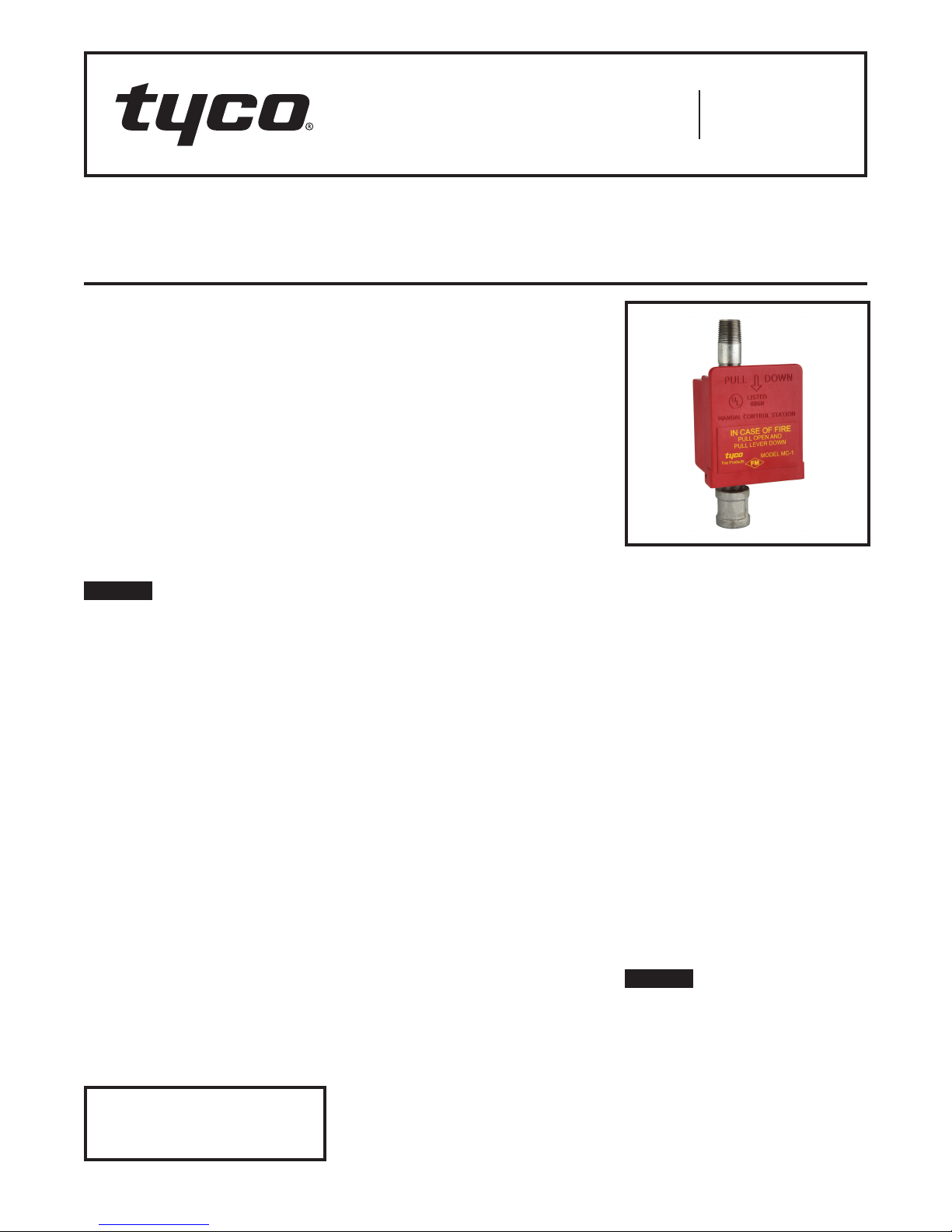
Model MC-1 (MC-2) Manual Control Station
For Deluge And Preaction Systems
Manual Release Service
Assembly
General
The box and cover in Figure 1 are thermoplastic. The elastomer water seal is TEFLON.
Description
The TYCO Model MC-1 (MC-2) Manual
Control Station provides a tamper
resistant means for emergency release
(that is, operation) of TYCO Automatic
Water Control Valves. Interconnection with the valves may be direct via
hydraulic (wet) pilot line or indirect via
pneumatic (dry) pilot line to a Model
DP-1 Dry Pilot Actuator.
The MC-2 Manual Control Station is a
modified MC-1 designed for use as a
trim component for the Model DV-5a
Automatic Water Control Valve.
NOTICE
The Model MC-1 Manual Control
Station described herein must be
installed and maintained in compliance
with this document, as well as with the
applicable standards of the NATIONAL
FIRE PROTECTION ASSOCIATION, in
addition to the standards of any other
authorities having jurisdiction. Failure
to do so may impair the performance
of these devices.
The owner is responsible for maintaining their fire protection system and
devices in proper operating condition.
The installing contractor or sprinkler
manufacturer should be contacted with
any questions.
Technical
Data
Approvals
UL and UL Listed
FM Approved
Working Water Pressure
20 to 300 psi (1,4 to 20,7 bar)
Minimum Ambient Temperature
Dry Pilot Lines: −50°F (−46°C)
Wet Pilot Lines: 40°F (4°C)
IMPORTANT
Refer to Technical Data Sheet
TFP2300 for warnings pertaining to
regulatory and health information.
Operation
Operating instructions are imprinted on
the Cover, and the Cover is hinged to
the Box and is held up in its normally
closed position by a polystyrene Break
Rod. The Break Rod is inserted through
corresponding holes in the top of the
Cover and interior of the Box, and the
Break Rod does not extend above the
top of the Cover so as to prevent unnoticed tampering (that is, the Cover can
only be opened by breaking the Break
Rod).
After actuation of the MC-1, interference between a boss on the interior
of the Cover and the Operating Lever
prevents closing of the Cover, before
the Operating Lever is raised. As an
added precaution, the Cover has been
weighted such that it will not remain
closed unless a Break Rod has been
placed in position.
Opening of the Model MC-1 Manual
Control Station relieves hydraulic or
pneumatic pressure, as applicable,
which permits the automatic water
control valve to open and allow a flow
of water into the system piping.
Installation
When the TYCO Model MC-1 (MC-2)
Manual Control Station is provided as
a trim component for TYCO Automatic
Water Control Valves, MC-1 (MC-2)
must be installed in accordance with
the specific instructions provided with
the TYCO Automatic Water Control
Valve Technical Data Sheets.
When the MC-1 is utilized for remote
locations on either wet or dry pilot lines,
the following instructions apply:
Step 1. The piping to the MC-1 is to
be securely mounted, and the MC-1 is
to be located 4-1/2 ft to 6 ft above the
floor/ground level.
Step 2. The MC-1 is to be installed vertically (so that the Cover will fall open
when the Break Rod is not in place), in
plain view, and in a readily accessible
location.
Step 3. When used with a wet pilot line,
piping from the outlet of the MC-1 is
to be directed to a suitable drain such
that there will be no accidental damage
to property or danger to persons when
the MC-1 is operated. When used on
dry pilot lines, the outlet piping is to be
directed towards the rear of the MC-1
and away from the operator.
Design
Criteria
The TYCO Model MC-1 (MC-2) Manual
Control Station located at the TYCO
Automatic Water Control Valve is to be
reset in accordance with the specific
instructions provided with the TYCO
Automatic Water Control Valve Technical Data Sheets.
When the MC-1 is utilized for remote
locations on either wet or dry pilot
lines, it is reset by raising the Operating Lever, closing the Cover, and inserting a replacement Break Rod.
NOTICE
In order to ensure the proper maximum
pull open force for the Cover, use only
P/N 92-289-1-008 replacement Break
Rods.
It is recommended that a supply of
spare Break Rods be maintained on
hand.
Page 1 of 2 AUGUST 2018 TFP1382
Page 2
TFP13 82
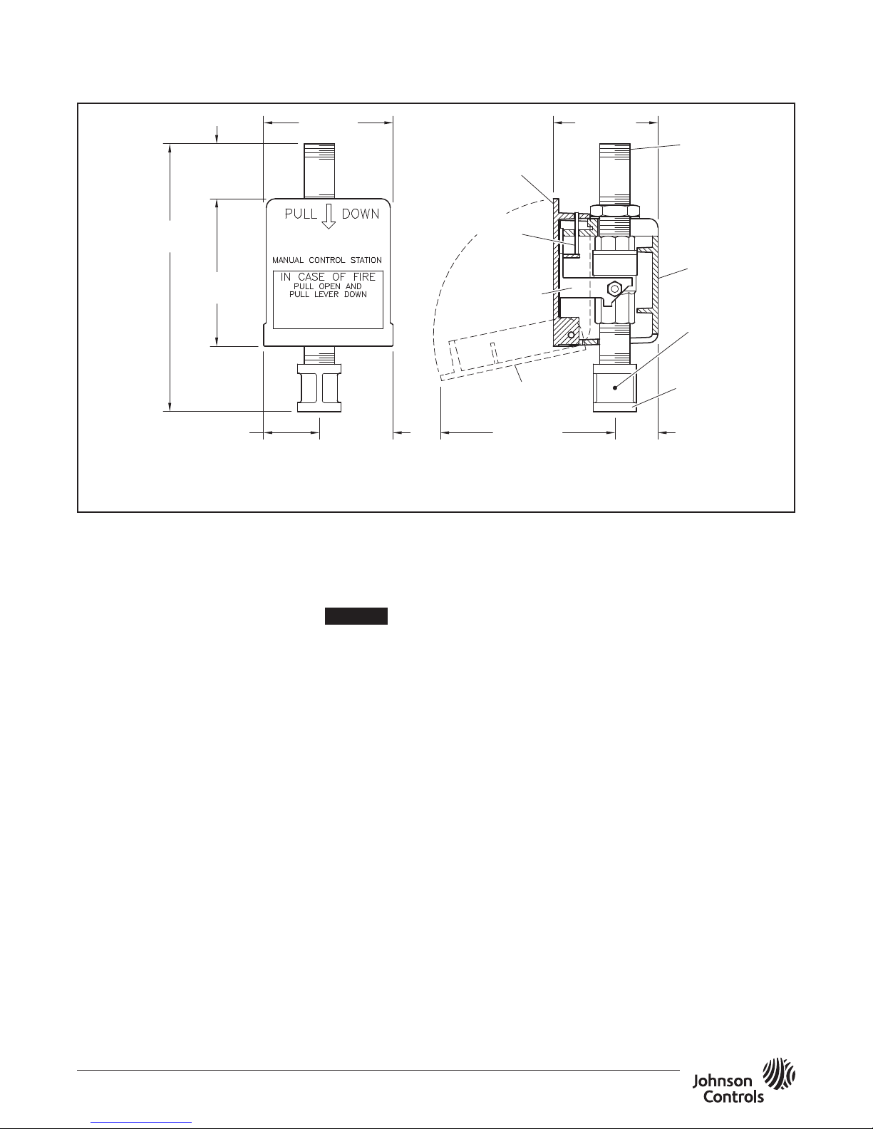
3-9/16"
2-7/8"
(30,2 mm)
(123,8 mm)
(52,4 mm)
(38,4 mm)
(188,7 mm)
Page 2 of 2
1-1/2"
(38,4 mm)
7-7/16"
4-1/8"
(104,8 mm)
1-1/2"
Note: When the MC-1 is ordered as a MC-2 repair trim component for the Model DV-5a
Automatic Water Control Valve, the assembly is provided without the drain coupling.
MODEL MC-1 (MC-2) MANUAL CONTROL STATION
Care and
Maintenance
The following inspection procedure
must be performed as indicated, in
addition to any specific requirements
of the NFPA, and any impairment must
be immediately corrected.
Before closing a fire protection system
control valve for inspection or maintenance work on the fire protection
system that it controls, permission to
shut down the effected fire protection
system must first be obtained from
the proper authorities and all personnel who may be affected by this action
must be notified.
The owner is responsible for the
inspection, testing, and maintenance of
their fire protection system and devices
in compliance with this document, as
well as with the applicable standards
of the NATIONAL FIRE PROTECTION
ASSOCIATION (e.g., NFPA 25), in addition to the standards of any authority
having jurisdiction. The installing contractor or product manufacturer should
be contacted relative to any questions.
Automatic sprinkler systems are recommended to be inspected, tested,
and maintained by a qualified Inspection Service.
(90,5 mm)
COVER
HANDLE
BREAK
ROD
OPERATING
LEVER
2-1/16"
FIGURE 1
After placing a fire protection system
in service, notify the proper authorities
and advise those responsible for monitoring proprietary and/or central station
alarms.
NOTICE
Unless appropriate precautions are
taken, operation of the MC-1 (MC-2)
when performing an inspection will
result in operation of the deluge or preaction systems and/or alarms.
Notify the owner and the fire department, central station, or other signal
station to which the system serves or
alarms are connected before performing inspections.
The Model MC-1 (MC-2) Manual
Control Station must be inspected
quarterly in accordance with this
section.
Step 1. Verify that the MC-1 (MC-2)
opens with ease when operated.
Step 2. Verify that flow out of the MC-1
(MC-2)increases to a rate which will trip
the deluge or preaction valve.
Step 3. Inspect the drain for evidence of continued leakage past the
MC-1 (MC-2). Determine and correct
the cause of the leakage problem, as
applicable.
Step 4. Verify that the MC-1 (MC-2)
is reset properly using only a
P/N 92-289-1008 Break Rod.
COVER
(OPEN)
4-7/8"
(73,0 mm)
1/2" NPT
INLET
BOX
SEE
NOTE
1/2" NPT
OUTLET
(DRAIN)
1-3/16"
Limited
Warranty
For warranty terms and conditions, visit
www.tyco-fire.com.
Ordering
Procedure
Contact your local distributor for availability. When placing an order, indicate
the full product name and Part Number
(P/N).
MC -1
Specify: Model MC-1 Manual Control
Station with galvanized steel fittings,
P/N 52-289-2-001
MC-2
Specify: Model MC-1 (MC-2) Manual
Control Station with galvanized steel
fittings for use with DV-5a Valve,
P/N 54-500-2-000
Note: Contact your local distributor
for MC-1 and MC-2 with black steel
fittings.
Replacement Break Rod
Specify: Replacement Break Rod for
Model MC-1 Manual Control Station,
P/ N 92- 289 -1-0 0 8
1400 Pennbr ook Pa rkwa y, Lans dale, PA 1944 6 | Teleph one +1-215- 362-070 0
© 2018 John son Control s. All right s reserved. A ll specifica tions and ot her informa tion shown wer e current as o f document rev ision date an d are subject t o change wit hout notice.
NATIONAL FIRE P ROTECTION ASSOCIATIO N and NFPA are register ed trademarks of N ational Fire Protec tion Associati on;
TEFLON is a regi stered tradema rk of DuPont
 Loading...