

Page 1
™
LOT
Use By
Status: Approved Doc#: AW10001726 Effective Date: nulldate
kENDALL
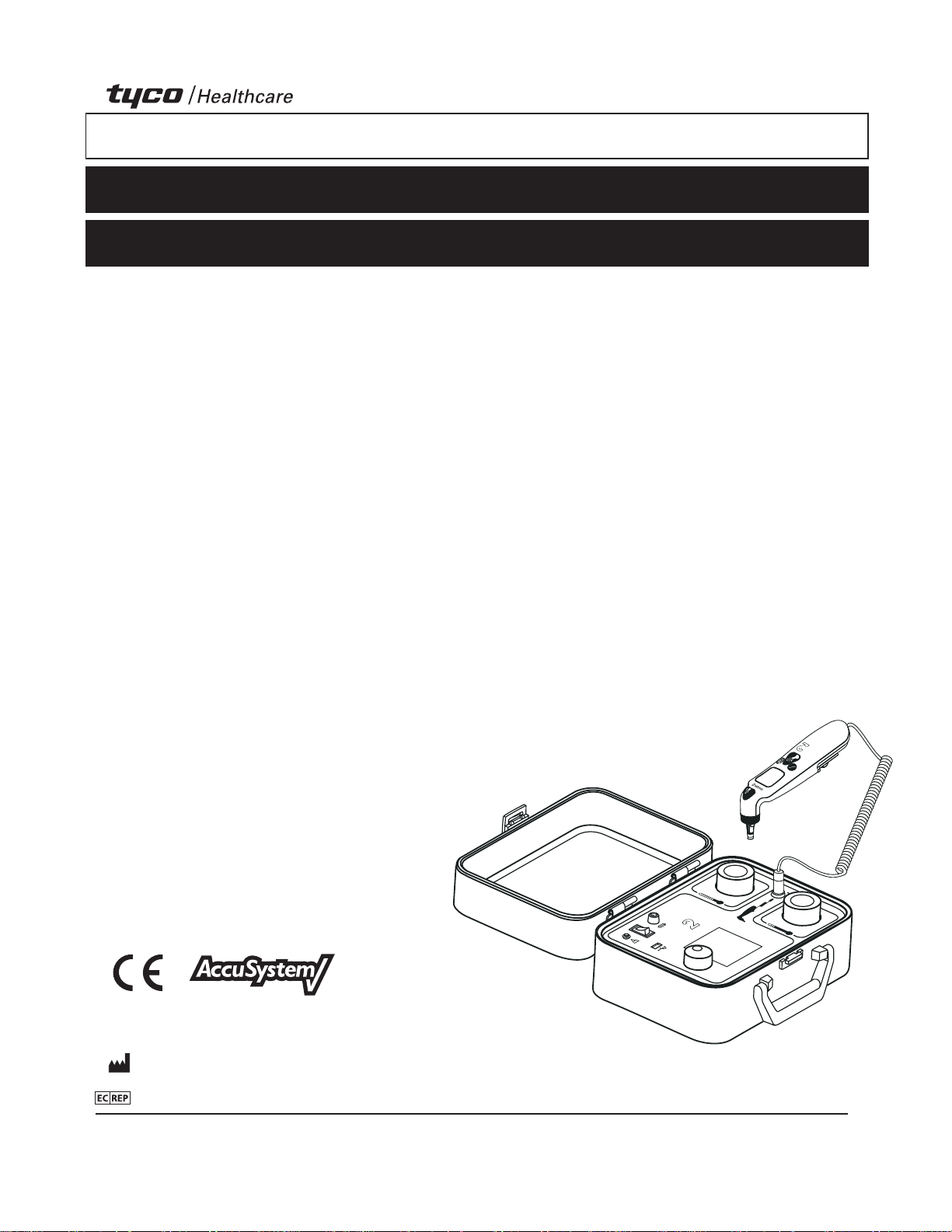
GENIUS™
2
Checker / Calibrator
Checker / Calibrator
Operation and Service Manual
Appareil de vérification/Calibrateur
Manuel d’utilisation et d’entretien
Prüfgerät/Kalibrator
Benutzer- und Service-Handbuch
Sistema di controllo della
calibrazione/calibratore
Manuale operativo e di assistenza
Verificador de calibración
Manual de operación y servicio
Kalibreringsenhet
Användar- och servicemanual
Validator
Gebruiks- en onderhoudshandleiding
Verificador/Calibrador
Manual de utilização e assistência
Ελεγκτής βαθμονόμησης
Εγχειρίδιο λειτουργίας και σέρβις
Ověřovač/Kalibrátor
Uživatelská a servisní příručka
Ellenőrző/kalibráló készülék
Működtetési és karbantartási kézikönyv
Контрольно-измерительное
устройство/Калибратор
Руководство по эксплуатации и
техническому обслуживанию
Kalibrator
Instrukcja obsługi i serwisowania
Kontrolör/Kalibratör
Kullanım ve Servis Kılavuzu
Kontroll- og kalibreringsapparat
Bruker- og servicehåndbok
™
™
GENIUS
F
º
C
º
Kalibrointilaite
Käyttö- ja huolto-opas
Kontrol- og kalibreringsapparat
Betjenings- og servicehåndbog
GENIUS
Checker / Calibrator
™ Trademark of Tyco Healthcare Group LP or its affiliates.
TYCO HEALTHCARE GROUP LP • 15 HAMPSHIRE ST. • MANSFIELD, MA 02048 • MADE IN U.S.A. • ©2008 TYCO HEALTHCARE GROUP LP • ALL RIGHTS
RESERVED • 090909 • PRODUCT INFO IN U.S. • 1-800-962-9888 • www.tycohealthcare.com
TYCO HEALTHCARE U.K. LTD GOSPORT, PO13 0AS, U.K.
182563-01
10/23/2008 Artwork#s: WN 182563-01 Job#: 16245
F/C˚
™
F/C˚
Page 2

Status: Approved Doc#: AW10001726 Effective Date: nulldate
Table of Contents
English
Page
Section I - Functional Description ...................................................................................................................................................1
Section II - Precautions and Warnings ........................................................................................................................................... 2
Section III - Icon Identification ........................................................................................................................................................ 3
Section IV - Required Equipment .................................................................................................................................................... 4
Section V - System Setup .................................................................................................................................................................. 4
Section VI - Operational Procedure ................................................................................................................................................. 5
Apply Power .................................................................................................................................................................................. 5
Start-up Screen ............................................................................................................................................................................. 5
Reminder Screen ........................................................................................................................................................................... 5
Main Menu .................................................................................................................................................................................... 5
Preferences .................................................................................................................................................................................... 5
Language Selection ....................................................................................................................................................................... 5
Set User/Site Information .............................................................................................................................................................. 5
Set Date and Time ......................................................................................................................................................................... 6
Check Calibration ........................................................................................................................................................................... 6
Section VII - Error Messages ............................................................................................................................................................. 8
Section VIII - Checker/Calibrator Specifications............................................................................................................................ 9
Section IX - Cleaning Instructions ................................................................................................................................................... 9
Section X - Troubleshooting ........................................................................................................................................................... 10
Section XI - Customer Service ........................................................................................................................................................ 11
Section XII - Warranty ..................................................................................................................................................................... 11
Section XIII - Electromagnetic Conformity Declaration ............................................................................................................. 12
This product contains software solely owned by Tyco Healthcare Group LP. Tyco Healthcare Group LP grants the user a non-exclusive,
limited license to use the software according to the operating instructions. A copy of the license can be obtained from Tyco Healthcare
Group LP.
10/23/2008 Artwork#s: WN 182563-01 Job#: 16245
Page 3
Status: Approved Doc#: AW10001726 Effective Date: nulldate
Section I - Functional Description
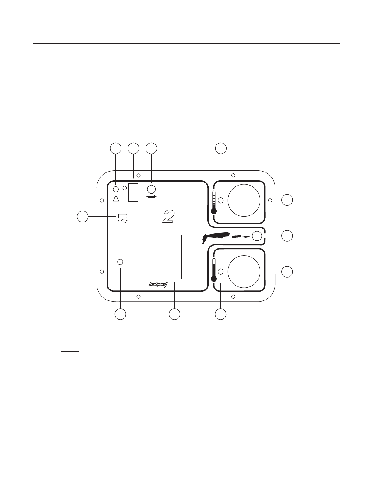
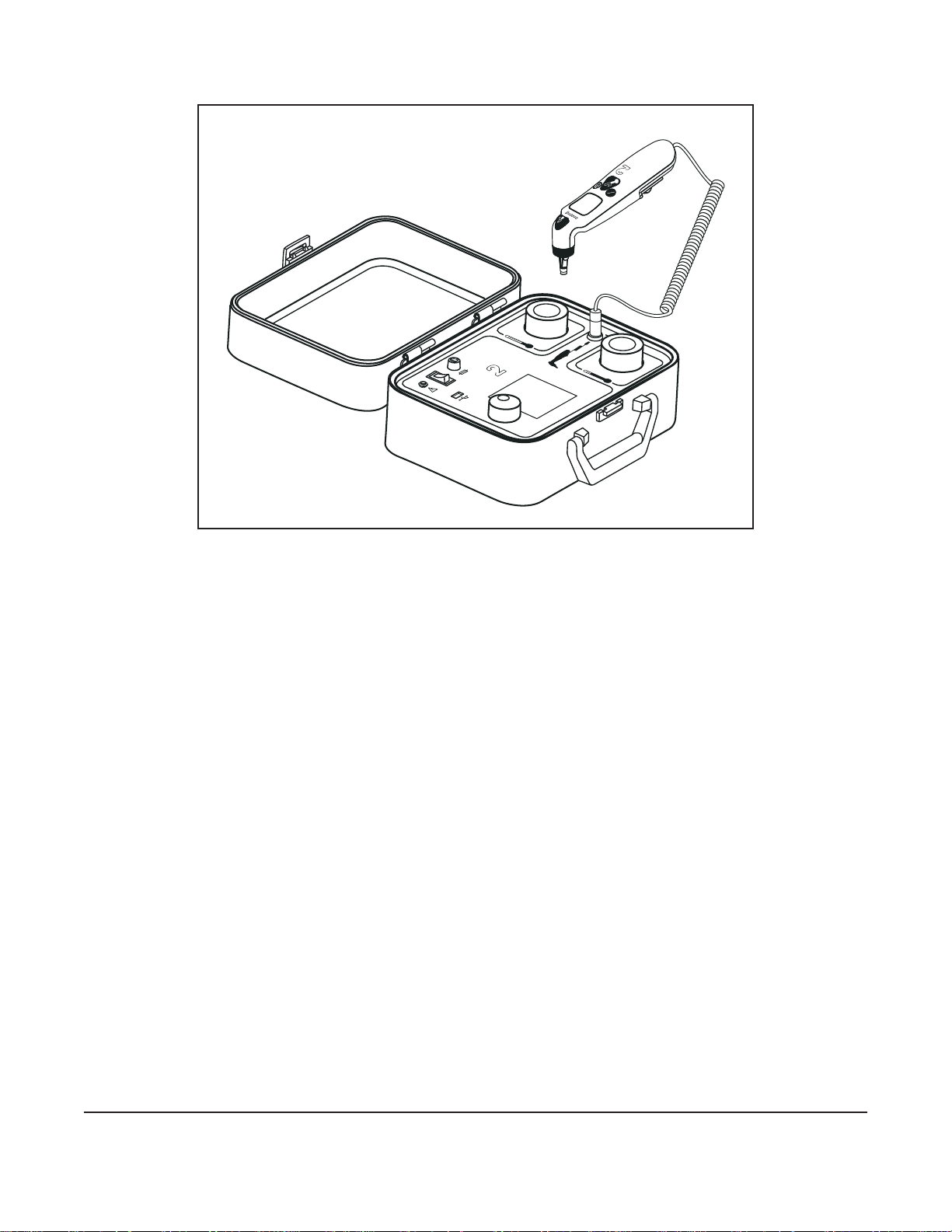
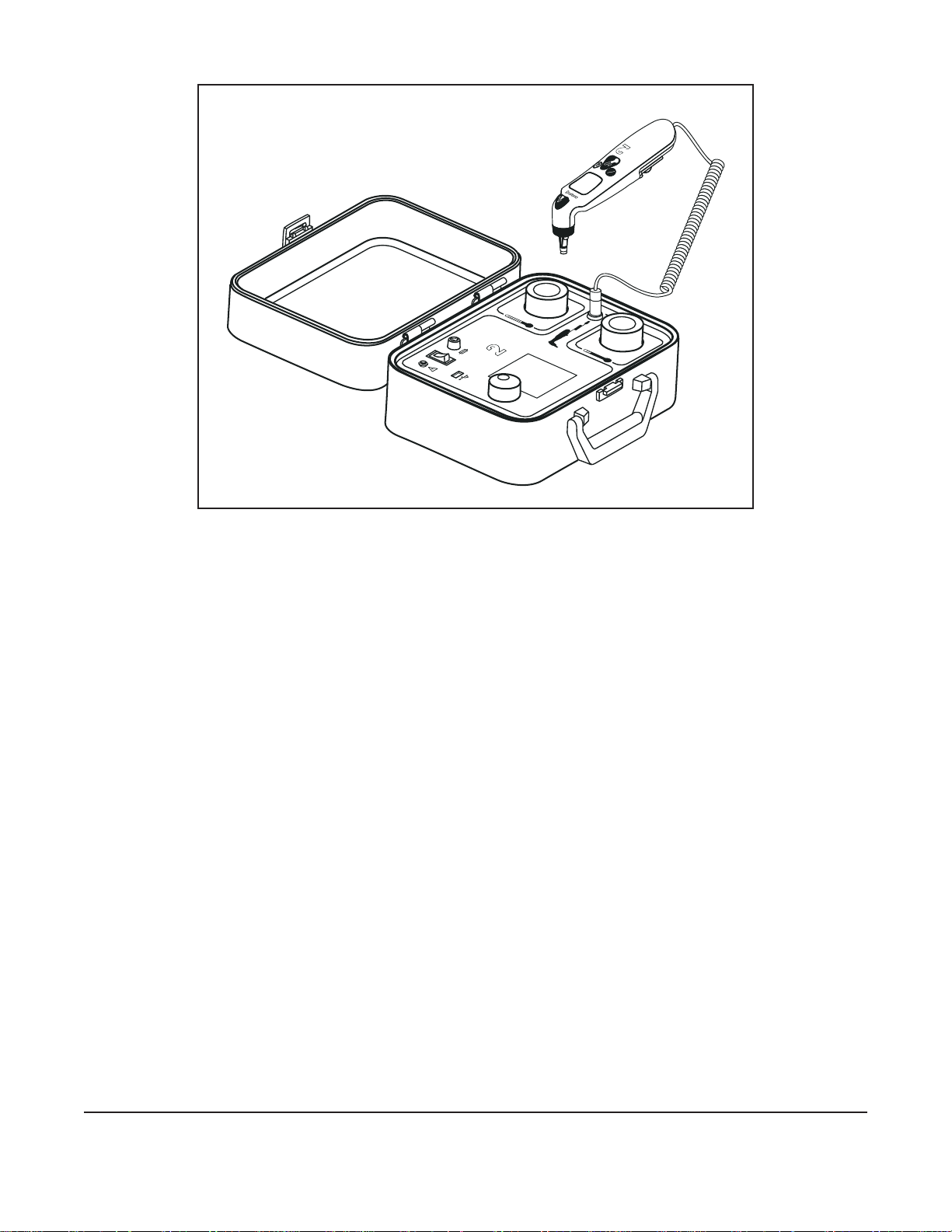
This manual describes the operation of the GENIUS 2 Checker/Calibrator. This device has been developed to check the accuracy
of the GENIUS 2 Tympanic Thermometer and automatically recalibrate the thermometer, if necessary. In addition, the GENIUS 2
Checker/Calibrator has the capability to generate a test report for each thermometer tested and save it to a USB ash drive. The
GENIUS 2 Checker/Calibrator will work with all GENIUS 2 Thermometer software revisions.
The GENIUS 2 Checker/Calibrator contains two independently controlled infrared calibration targets that are similar to factory
calibration targets. These “blackbody” targets are designed to have ecient radiative heat transfer and produce infrared radiation
that approximates the human ear at temperatures of 32.2° C (90.0° F ) and 40.6° C (105.0° F ).
1 2 3 4
F 3.15A 250V
11
GENIUS
™
F/C˚
Checker / Calibrator
™
F/C˚
8 910
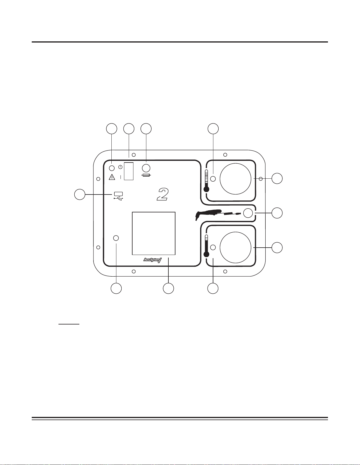
Figure 1 - Front Panel Layout
Legend
1 Power Connector 7 High Temperature Target
2 Power Switch 8 High Temperature Target LED
3 Fuse Holder 9 LCD Display
4 Low Temperature Target LED 10 Encoder Knob
5 Low Temperature Target 11 USB port
6 GENIUS 2 Thermometer Connector
5
6
7
GENIUS™ 2 Checker / Calibrator
1
10/23/2008 Artwork#s: WN 182563-01 Job#: 16245
Operation and Service Manual
Page 4

Status: Approved Doc#: AW10001726 Effective Date: nulldate
Section II - Precautions and Warnings
• The GENIUS 2 Checker/Calibrator is designed to be operated as specified in this manual. Protection provided by the safety
devices in the GENIUS 2 Checker/Calibrator may be impaired if the device is not used in accordance with the directions contained
in this manual.
• The GENIUS 2 Checker/Calibrator enclosure is not waterproof. Avoid spilling liquid of any kind onto the front panel of the device.
Likewise, the GENIUS 2 Checker/Calibrator is powered from an AC power source. Avoid the potential for contact between liquid
and any external surface of the device while connected to the mains source.
• The surface quality of the interior of the reference blackbody targets is critical to their operation as efficient infrared radiators.
Care should be exercised when working near the entrance to the blackbody targets to ensure that no contact is made with the
surface inside the rubber flaps.
• In the event of a blown fuse, replace the fuse with a fuse that exactly matches the rated voltage, current, and form factor as
specified in the GENIUS 2 Checker/Calibrator Specifications section of this manual. Make sure the device is disconnected from
the AC power source before changing a blown fuse.
• This device should not be used in the presence of flammable anesthetics. There is risk of an explosion in the presence of these
anesthetics.
• There are no user-serviceable components in this device. Do not remove the front panel. Refer servicing to qualified service
personnel.
• Use only the supplied power module with this device.
• When prompted to insert the GENIUS 2 Thermometer into one of the blackbody targets, there is a 60 second window of time to
accomplish the insertion. If the time delay exceeds this period, the procedure will be terminated.
• Prior to checking/calibrating a GENIUS 2 Thermometer, ensure that the thermometer lens is clean. Effective cleaning will ensure
that the calibration tolerances are correctly verified. Refer to the cleaning instructions in the Genius 2 Thermometer operating
manual.
• When installing a GENIUS 2 probe cover on to the tip of the GENIUS 2 Thermometer, use only covers that are in a cassette and
not released. Try to avoid all hand contact with the probe covers in order to prevent inaccurate readings. Do not reuse probe
covers. Use only GENIUS 2 probe covers.
• Let the GENIUS 2 Checker /Calibrator warm up after power-up for at least 15 minutes before use. Make sure that the GENIUS 2
Thermometers, probe covers and the GENIUS 2 Checker/Calibrator have had enough time to equilibrate to room temperature
before proceeding. Allow a longer warm up period if the device or thermometers were at the extreme limits of allowed
ambient temperature. The portability of the GENIUS 2 Checker/Calibrator will allow for relocation of the device to areas that
meet the ambient temperature requirements.
• To maintain Electromagnetic Compatibility (EMC) conformance, use a USB flash drive that is CE marked and meets EN55022
standard.
• Do not put or rest the GENIUS 2 Thermometer on the surface of the GENIUS 2 Checker/Calibrator at any time. The thermal
sensors inside the thermometer probe tip will detect the heat transferred from the blackbody targets through the front panel
surface. This will cause instability of the thermometer sensors, which will produce erroneous temperature readings.
• The GENIUS 2 Checker/Calibrator may only be used indoors, in an area free from drafts and wide ambient temperature swings.
• The USB port on the front panel is intended to be used with only a USB Flash memory drive. No other USB devices should be
inserted into the USB port. The USB flash memory drive should be installed prior to device power-up.
• In the event that the GENIUS 2 Checker/Calibrator is dropped, return the unit to the factory for re-calibration.
GENIUS™ 2 Checker / Calibrator
2
10/23/2008 Artwork#s: WN 182563-01 Job#: 16245
Operation and Service Manual
Page 5
SN
Status: Approved Doc#: AW10001726 Effective Date: nulldate
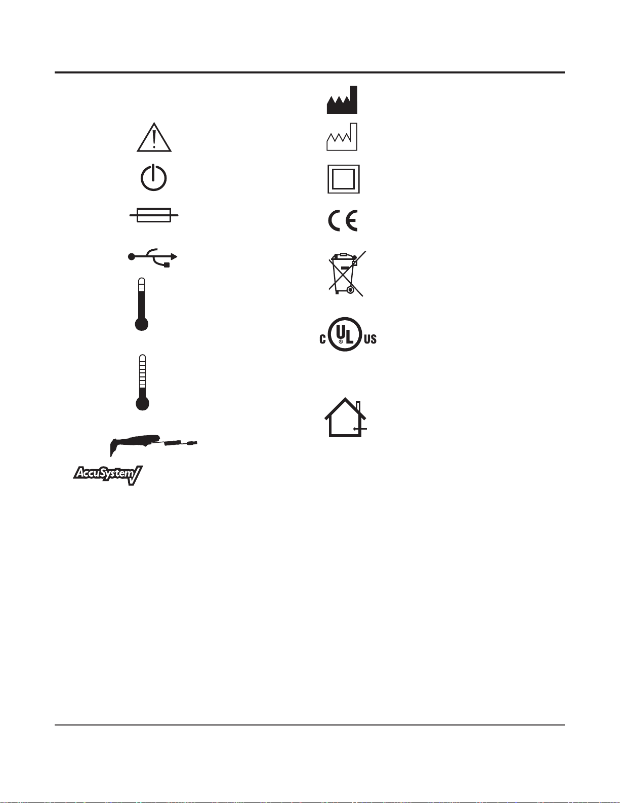
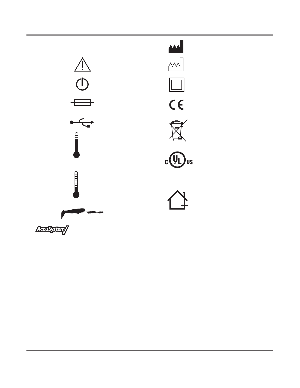
Section III - Icon Identification
F/C˚
Serial Number
Consult Accompanying
Documents
Standby Power
Replace with Same
Rated Fuse
USB Port Dispose of as Electrical
High Temperature Target
LISTED
(LABORATORY EQUIPMENT)
46EA
Low Temperature Target
Manufacturer
Date of Manufacture
Double or Reinforced
Insulation Protection
CE Mark
and Electronic Waste
UL Listing Information
F/C˚
Caution: Indoor Use Only
GENIUS 2 Thermometer
Connection
™
The GENIUS 2 Infrared Tympanic Thermometer is a reliable and accurate temperature-taking device. The reason for the
accuracy of the GENIUS 2 Thermometer is the design, controlled calibration methods and stringent manufacturing controls. One
of the most critical functional parts of a thermometer is the ACCUSYSTEM√ probe cover produced by Tyco Healthcare/Kendall. The
GENIUS 2 Thermometer ACCUSYSTEM√ probe cover, when placed on a GENIUS 2 Thermometer, serves as an infection control barrier
between the patient and the device and the medium for heat transmission from the patient to the thermometer. The functionality
of the GENIUS 2 Thermometer ACCUSYSTEM√ probe cover is extremely important for preventing device contamination and also for
allowing accurate patient temperature measurements.
The reason the GENIUS 2 Infrared Tympanic Thermometer and GENIUS 2 Thermometer ACCUSYSTEM√ probe covers have
satised our customers’ expectations is due to the integration of these two parts during the manufacturing process. The GENIUS 2
Thermometer ACCUSYSTEM√ probe cover molding process parameters are tightly controlled at Tyco Healthcare/Kendall to minimize
variation and produce consistent and reliable products. The special grades of thermoplastic materials are also tightly controlled and
are specically chosen to deliver consistent temperature measurements with GENIUS 2 Thermometers. The factory calibration and
nal determination of an acceptable GENIUS 2 Thermometer is dependent on the use of acceptable Tyco Healthcare/Kendall
GENIUS 2 Thermometer ACCUSYSTEM√ probe covers. The use of generic probe covers or other probe covers not produced by
Tyco Healthcare/Kendall is not supported or sanctioned by Tyco Healthcare/Kendall. The use of unauthorized GENIUS 2 Thermometer
probe covers could jeopardize the accuracy of the GENIUS 2 Thermometer. Check your probe cover carton for the ACCUSYSTEM√ logo
to be certain that your thermometer will deliver an accurate temperature every time it is utilized.
GENIUS™ 2 Checker / Calibrator
3
10/23/2008 Artwork#s: WN 182563-01 Job#: 16245
Operation and Service Manual
Page 6
Status: Approved Doc#: AW10001726 Effective Date: nulldate
Section IV - Required Equipment
1. GENIUS 2 Checker/Calibrator
2. Power module with AC adapter
3. Probe cable
4. Operator’s Manual
5. GENIUS 2 Thermometers to be tested
6. GENIUS 2 disposable probe covers
7. Small Phillips screwdriver
Section V - System Setup
The following actions should precede use of the GENIUS 2 Checker/Calibrator:
1. Connect the correct AC plug adapter for your country to the power module.
2. Connect the power module cable to the power jack on the front panel.
3. Connect the power module to an AC power outlet.
4. Turn the unit on via the switch on the front panel.
5. Let the GENIUS 2 Checker/Calibrator unit warm up for at least 15 minutes.
6. Set aside a cassette with new GENIUS 2 probe covers.
7. Let the GENIUS 2 Thermometers equilibrate to the room temperature.
8. Prepare the GENIUS 2 Thermometers by thoroughly cleaning the lenses prior to use. Refer to the GENIUS 2 Thermometer
operating manual for cleaning instructions.
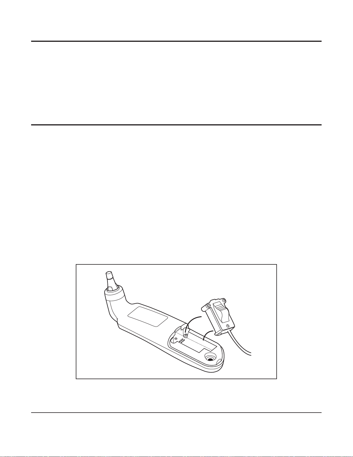
9. Remove the battery compartment access panel by using a small Phillips screwdriver. Remove all three AAA batteries.
10. Connect the probe cable round connector to the front panel of the GENIUS 2 Checker/Calibrator.
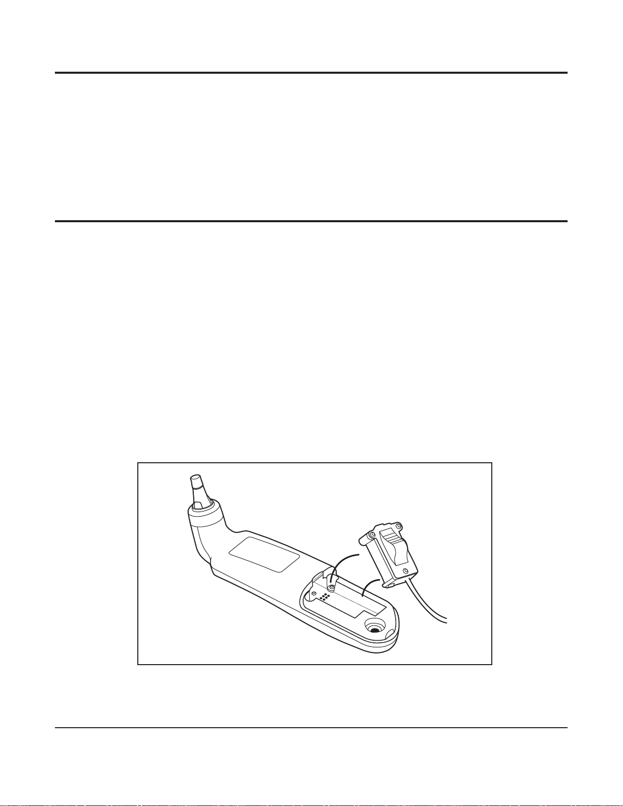
11. Connect the other end of the probe connector into the battery compartment. The connector will snap into place where the
batteries were. Refer to Figure 2.
Figure 2 - Insertion of Probe Connector into GENIUS 2 Battery Compartment
GENIUS™ 2 Checker / Calibrator
4
10/23/2008 Artwork#s: WN 182563-01 Job#: 16245
Operation and Service Manual
Page 7

Status: Approved Doc#: AW10001726 Effective Date: nulldate
Section VI - Operational Procedure
The following procedure will describe the steps required to operate the GENIUS 2 Checker/Calibrator. In order to facilitate familiarity
with the product, it would be advisable to use this section of the manual during the calibration check of the rst few thermometers.
Installation of USB Flash Drive (Optional)
Install a USB ash drive into the USB port located on the front panel if a report le written to the USB ash drive is desired. If the USB
ash drive is installed after performing a calibration check, an error message may occur when attempting to write the report le if
the operator does not wait for the USB ash drive to complete initialization. If the GENIUS 2 Checker/Calibrator is powered o, all
internal memory (not yet saved to the USB ash drive) will be lost.
Apply Power
Make sure the AC-adapter end of the power module is plugged into a grounded outlet. Connect the power module to the front panel
power connector. Apply power to the GENIUS 2 Checker/Calibrator by using the power switch on the front panel.
Start-up Screen
The rst screen on the LCD display is the Initialization Screen, which displays the software revision and date of the GENIUS 2
Checker/Calibrator. If there is an internal problem during initialization, an Error screen will be displayed (See Section VII).
Reminder Screen
The next screen on the LCD display is a reminder to let the GENIUS 2 Checker/Calibrator warm-up for at least 15 minutes after
applying power. This will let the infrared blackbody targets warm up to the proper temperatures. To exit this screen, press the
encoder knob.
Main Menu
The Main Menu screen is displayed next. This screen has four menu options:
Check Calibration
Preferences
Set User/Site Information
Set Time/Date
To enter any menu option, use the encoder knob to scroll over and highlight the desired menu option, then press the encoder knob.
Preferences
The Preferences menu is used to setup the language option. Press the encoder knob to enter the Language Selection screen.
Language Selection
The Language Selection screen lists the available languages for the LCD screen text. To select a language, scroll over the selection and
it will be highlighted. Press the encoder knob to complete the selection and return to the Main Menu screen. The selected language
will be stored in non-volatile memory and will be used next time the unit is powered on.
Set User/Site Information
The Set User/Site Information screen is used to enter the operator’s name and the organization and/or site information. This
information will be written to the test report le.
To enter the information, use the encoder knob to scroll through the alphabet for a given letter position in the operator name or site
information. When the correct letter is shown, press the encoder knob to select the letter and advance to the next letter position. To
enter a space, just press the encoder knob when a space or blank letter is shown in that letter position. The user name can be up to
20 letters long. Use the encoder knob to scroll to the organization eld and enter a name for the site in a similar manner. To exit the
menu, scroll to the DONE text and press the encoder knob.
GENIUS™ 2 Checker / Calibrator
10/23/2008 Artwork#s: WN 182563-01 Job#: 16245
5
Operation and Service Manual
Page 8

Status: Approved Doc#: AW10001726 Effective Date: nulldate
Set Date and Time
The Set Date and Time screen menu option is used to setup the date and time that is used on the test report. The time and date are
internally stored and automatically updated when the unit is powered up.
To enter time, use the encoder knob to select the hours and minutes. Note: the hours is setup using a 24 hour clock format, where
1PM is entered as 13:00 etc. When the value is correct, push the encoder knob to move to the next eld of the time and then to the
date eld. The date eld is setup using a MMDDYYYY format. After the last eld of the date is entered, the next encoder push will exit
this menu and return to the Main Menu. Note: the time and date are shown at the bottom of the Main Menu.
Check Calibration
This menu option performs the calibration check of a GENIUS 2 Thermometer, and if required, automatically recalibrates the
thermometer using a series of step-by-step screens. Before entering this menu option, make sure that the required equipment listed
in Section IV is available. This includes a cassette with unused (new) probe covers.
Step 1:
Warm up of infrared blackbody targets. This screen is displayed while the targets are checked for proper temperature. Both the Low
Target and the High Target are checked, and when they are at the correct temperature, the screen will change to “OK” for each target.
There is a prompt to press the encoder knob to continue to the next screen. If either target cannot reach the correct temperature,
an Error message screen will be displayed. If this happens, check to be sure the GENIUS 2 Checker/Calibrator is within the correct
ambient (room) temperature range, and has been given at least 15 minutes of warm up time since power was switched on.
Step 2:
Inspect the GENIUS 2 Thermometer that will be tested. Ensure that the thermometer lens is not scratched and is free from ear
wax and/or other contaminants. If the thermometer lens is “dirty”, clean the lens according to the instructions in the GENIUS 2
Thermometer operating manual. Once the thermometer lens is clean, connect the GENIUS 2 Thermometer to the Checker/Calibrator
by plugging the round end of the thermometer interface cable into the round connector socket on the GENIUS 2 Checker/Calibrator
front panel (refer to Figure 3). Open the battery door of the thermometer by using a small Phillips screwdriver. Remove the batteries
and set aside. Connect the other end of the thermometer probe cable into the battery compartment, making sure the connector
“snaps” into place securely. Refer to Figure 2 in Section V.
Note: A new probe cover must be used prior to every target insertion. Finger oils on previously used probe covers or re-used
probe covers that have been heated by GENIUS 2 Checker/Calibrator target can cause erroneous readings which may
result in a failed calibration check or recalibration. Therefore, it is extremely important that a new probe cover is used
each time.
Step 3:
Press the encoder knob to continue, then install a new GENIUS 2 probe cover onto the GENIUS 2 Thermometer. Make sure to use a
cover that is held in the cassette. Once the cover is on the thermometer, do not point the probe tip at any object, including hands,
ngers or LCD display, as this will cause an inaccurate temperature reading. Inspect the probe cover to make sure it is fully seated (no
space between the cover and the tip base) and no holes, tears, or wrinkles are present in the plastic lm. When the cover is on, insert
the probe tip into the Low temperature target, which will have a blinking LED indicator next to it. Make sure that the probe tip is fully
inserted into the target well. Refer to Figure 3 for proper insertion. In order to avoid a time-out error, insert the covered probe tip into
the target within 60 seconds from the time the encoder knob is pressed.
GENIUS™ 2 Checker / Calibrator
6
10/23/2008 Artwork#s: WN 182563-01 Job#: 16245
Operation and Service Manual
Page 9
Status: Approved Doc#: AW10001726 Effective Date: nulldate
™
GENIUS
F
º
C
º
™
F/C˚
™
GENIUS
Checker / Calibrator
F/C˚
Figure 3 - Proper Insertion of GENIUS 2 Probe Tip into Target
Step 4:
The insertion of the probe tip into the target will automatically be detected and the screen display will change to “Press GENIUS 2
Thermometer scan button.” Press the scan button on the GENIUS 2 Thermometer while it is inserted into the Low temperature target.
The GENIUS 2 Thermometer will output 3 short beeps as it takes the temperature of the blackbody target. After the temperature is
taken, the next screen will display.
Step 5:
Withdraw the thermometer from the Low temperature target and eject the probe cover. The screen display will change to “Install a
new probe cover and insert probe into the High target.” Again, use a new GENIUS 2 probe cover from the cassette and be careful not
to point the probe tip at any object, including hands, ngers or LCD display. Inspect the probe covers to make sure it is fully seated
(no space between the cover and the tip base) and no holes, tears, or wrinkles are present in the plastic lm. When the cover is on,
insert the probe tip into the High temperature target, which will have a blinking LED indicator next to it. Make sure that the probe tip
is fully inserted into the target well.
Step 6:
The insertion of the probe tip into the High target will automatically be detected and the screen display will change to “Press
GENIUS 2 Thermometer scan button.” Press the scan button on the GENIUS 2 Thermometer while it is inserted into the High
temperature target. The GENIUS 2 Thermometer will output 3 short beeps as it takes the temperature of the blackbody target. After
the temperature is taken, the next screen will display.
Step 7:
If the GENIUS 2 thermometer is within specied accuracy limits, a Results screen will be displayed showing the thermometer serial
number along with an indication that the thermometer passed calibration check. If the GENIUS 2 thermometer is found to be outside
the specied accuracy limits , the display will indicate to the user that the GENIUS 2 Checker/Calibrator is entering into a calibration
sequence that requires the user to repeat Steps 3 through 6 three more times in order to gather recalibration data. Following the
last pass through Steps 3 through 6, the GENIUS 2 Checker/Calibrator will attempt to recalibrate the GENIUS 2 thermometer. If the
recalibration is successful, a Results screen will be displayed showing the thermometer serial number along with an indication that
the thermometer passed calibration. If the recalibration is unsuccessful or the thermometer is unable to be calibrated, a Results
screen will be displayed showing the thermometer serial number along with an indication that the thermometer failed calibration.
GENIUS™ 2 Checker / Calibrator
7
10/23/2008 Artwork#s: WN 182563-01 Job#: 16245
Operation and Service Manual
Page 10

Status: Approved Doc#: AW10001726 Effective Date: nulldate
Step 8:
After the pass/fail Results screen has been displayed, press the encoder knob to display a second Results screen containing the target
temperatures, the GENIUS 2 readings, and the target versus thermometer variances.
Step 9:
The next screen will display “Write report to USB ash drive?” and display Yes and No below. If a report is desired, insert a ash
drive into the front panel USB port. Note: allow about 30 seconds after insertion for the USB ash drive to initialize. Use the encoder
knob to scroll to either Yes or No and press the encoder knob to make a selection. If No is selected, the screen returns to the Main
Menu. If Yes is selected, a report is written to the USB ash drive, using the thermometer serial number for lename and .TXT as the
le extension. The le contains the test results as well as other information such as serial number, date, time, user name, and
organization. This le is a simple ASCII text le and is only available in English. This le can be read by MicrosoftTM Windows
programs such as Microsoft™ Notepad and sent to a printer. After the le is written, the display will show “Push knob to continue.”
Press the encoder knob to return to the Main Menu.
Step 10:
After completing a calibration check/recalibration, remove the probe connector from the battery compartment, using a rocking
motion to free the connector. Then reinstall the 3 AAA batteries, observing the proper polarity orientation. Finally, reinstall
the battery compartment cover and tighten the screw.
Step 11:
Remove USB ash drive before closing the lid of the case. The lid should be closed when the GENIUS 2 Checker/Calibrator is not in use.
Section VII - Error Messages
The error messages will have a number associated with them, such as Error 1, etc. The following is an explanation of the errors:
Error 1: Internal Error
This error is an indication of a problem within the GENIUS 2 Checker/Calibrator. If this error persists after cycling power o and
back on, return the unit for factory servicing.
Error 2: Unable to communicate with GENIUS 2 Thermometer.
This error is an indication of either a lack of communication or a miscommunication between the GENIUS 2 Thermometer and
the GENIUS 2 Checker/Calibrator. Check both ends of the thermometer probe cable, especially the end that connects inside
the battery compartment. The pins in the thermometer probe cable can lose spring action if they are bent or damaged. After
inspecting the probe cable, re-attempt the calibration check. If the problem persists, try a dierent GENIUS 2 Thermometer, if
available. If this does not resolve the problem, return the unit for factory servicing, along with the thermometer cable and the
GENIUS 2 Thermometer that indicated this error.
Error 3: Timeout
This error is an indication that the operator took too long to perform an operation. This error might be seen when connecting
to the GENIUS 2 Thermometer, or while installing a probe cover on the thermometer. The timeout is set for one minute. Try
repeating the operation that gave this error.
Error 4: Target Out of Range
This error is an indication that one of the blackbody targets is not within the range of temperature allowed. Check that the
unit is being operated within the allowed ambient temperature operating range. Refer to Section VIII. If operating within the
specied ambient conditions does not eliminate the error, the blackbody target(s) may be damaged. Return the unit for factory
servicing.
Error 5: USB Flash Drive Write Error
This error is an indication of a problem when writing the report le to a USB ash drive. Check that the write protect switch on
the USB drive is in the “o ” position. Make sure that there is sucient free space on the drive, and that security or encryption
features are not in use.
Error 6: Ambient Temperature Out of Range
This error is an indication that the ambient temperature is not within the specied range for performing an accurate recalibration.
Check that the unit is being operated within the allowed ambient temperature operating range. Refer to Section VIII.
GENIUS™ 2 Checker / Calibrator
10/23/2008 Artwork#s: WN 182563-01 Job#: 16245
8
Operation and Service Manual
Page 11

Status: Approved Doc#: AW10001726 Effective Date: nulldate
Error 7: Wrong Target
This error is an indication that the GENIUS 2 Thermometer has been inserted into wrong target or was inserted into the target
prematurely. Please take care to follow the instructions on the screen and not perform steps prior to the instructions being
displayed.
The Error screen will be displayed for 60 seconds before returning to the Main Menu. To exit the Error screen sooner, press the
encoder knob.
Section VIII - Checker/Calibrator Specifications
Temperature Set Points
Low Target . . . . . . . . . . . . . . . . . . . . . . . . . . . . . . . . . . . . . . . . . . . . . . . . . 32.2 °C +/- 0.3 °C (90.0 °F +/- 0.5 °F)
High Target . . . . . . . . . . . . . . . . . . . . . . . . . . . . . . . . . . . . . . . . . . . . . . . . 40.6 °C +/- 0.3 °C (105.0 °F +/- 0.5 °F)
Target Temperature Accuracy . . . . . . . . . . . . . . . . . . . . . . . . . . . . . . . . . . . . . . .Initial Limit +/- 0.03 °C (0.05 °F)
. . . . . . . . . . . . . . . . . . . . . . . . . . . . . . . . . . . . . . . . . . . . . . . . . . . . . . . . . . . . Post year 1 +/- 0.06 °C (0.10 °F)
GENIUS 2 Thermometer Accuracy After Recalibration*
Readings between 36. 0 °C and 39.0°C (96.8 °F and 102.2 °F) . . . . . . . . . . . . . . . . . . . . . . . . +/- 0.2 °C (+/- 0.4 °F)
Readings less than 36. 0 °C (96.8 °F) or greater than 39.0°C (102.2 °F) . . . . . . . . . . . . . . . . . . . . +/- 0.3 °C (+/- 0.5 °F)
Warm-up Time Before Use . . . . . . . . . . . . . . . . . . . . . . . . . . . . . . . . . . . .15 minutes (from non-extreme ambient)
Ambient Temperature Operating Range . . . . . . . . . . . . . . . . . . . . . . . . . . . . . . . . . . . . 21.1-26.7 °C (70-80 °F)
Relative Humidity Operating Range . . . . . . . . . . . . . . . . . . . . . . . . . . . . . . . . . . . 50 +/- 20%, non-condensing
Altitude Range . . . . . . . . . . . . . . . . . . . . . . . . . . . . . . . . . . . . . . . . . . . . . . . . . . Up to 2000 meters (6563 feet )
Storage Temperature Range . . . . . . . . . . . . . . . . . . . . . . . . . -25 °C - 55 °C (-13°F - 131°F ) 85% RH non-condensing
Approximate Size
Length . . . . . . . . . . . . . . . . . . . . . . . . . . . . . . . . . . . . . . . . . . . . . . . . . . . . . . . . . . . . . . . . 31.1 cm (12.25” )
Depth . . . . . . . . . . . . . . . . . . . . . . . . . . . . . . . . . . . . . . . . . . . . . . . . . . . . . . . . . . . . . . . . . .15.9 cm (6.25” )
Width . . . . . . . . . . . . . . . . . . . . . . . . . . . . . . . . . . . . . . . . . . . . . . . . . . . . . . . . . . . . . . . . . 26.0 cm (10.25” )
Weight . . . . . . . . . . . . . . . . . . . . . . . . . . . . . . . . . . . . . . . . . . . . . . . . . . . . . . . . . . . . . . . . . 3.3 kg (7.2 lbs )
Power Requirements. . . . . . . . . . . . . . . . . . . . . . . . . . . . . . . . . . . . . . . . . . . . . . . 100-240V 0.8-0.4A 47-63Hz
Fuse Requirements . . . . . . . . . . . . . . . . . . . . . . . . . . . . . . . . . . . . . . . . . . . . . Schurter FSF 5 x 20mm Fast Blow
. . . . . . . . . . . . . . . . . . . . . . . . . . . . . . . . . . . . . . . . . . . . . . . . . . . . . . . . . . Low Breaking Capacity 250 V, 3.15A
Recommended Checker/Calibrator Calibration Interval . . . . . . . . . . . . . . . . . . . . . . . . . . . . . . . . . . One Year
ESD Immunity . . . . . . . . . . . . . . . . . . . . . . . . . . . . . . . . . . . . . . . . Meets IEC 61000-4-2 Non-continuous Criteria C
Pollution Degree. . . . . . . . . . . . . . . . . . . . . . . . . . . . . . . . . . . . . . . . . . . . . . . . . . . . . . . . . . . . . . . . . . 2
Installation Category. . . . . . . . . . . . . . . . . . . . . . . . . . . . . . . . . . . . . . . . . . . . . . . . . . . . . . . . . . . . . . . II
. . . . . . . . . . . . . . . . . . . . . . . . . . . . . . . . . . . . . . . . . . . . . . . . . . . . . . . . . . . . . . . . . . . . . . Indoor Use Only
*Post recalibration accuracy using the GENIUS 2 Checker/Calibrator may not necessarily be equivalent to factory calibration
Section IX - Cleaning Instructions
CAUTION: DO NOT IMMERSE THE Checker/Calibrator, CABLES, OR POWER CORD IN WATER OR OTHER CLEANING SOLUTION; CLEAN
USING A DAMP (NOT WET) CLOTH. FAILURE TO FOLLOW CLEANING PROCEDURES DESCRIBED HEREIN COULD RESULT IN HAZARDS TO
USERS.
As with any AC powered electrical device, care must be taken to prevent liquid from entering the Checker/Calibrator to avoid
electrical shock hazard, re hazard, or damage to electrical components.
GENIUS™ 2 Checker / Calibrator
10/23/2008 Artwork#s: WN 182563-01 Job#: 16245
9
Operation and Service Manual
Page 12

Status: Approved Doc#: AW10001726 Effective Date: nulldate
General Cleaning Instructions
Cleaning of the GENIUS 2 Checker/Calibrator may be performed as follows:
• FIRST, UNPLUG THE GENIUS 2 Checker/Calibrator FROM POWER SOURCE. NEVER CLEAN THE DEVICE WHILE CONNECTED TO THE
MAINS SUPPLY.
• A mild detergent should be used for general cleaning of outside surfaces. Also, a cloth damped with isopropyl alcohol can be
used to clean the unit. DO NOT USE abrasives or solvents. Avoid excess moisture around the target assemblies and the electrical
connectors.
• Do not attempt to clean the target below the rubber flaps.
• Do not clean the target nests or flaps with alcohol.
If there is any doubt about the compatibility of a cleaning agent with part of this equipment or its materials contact
Tyco Healthcare/Kendall customer service (See Section XI).
Section X - Troubleshooting
Some of the common problems are as follows:
Problem Probable Cause Corrections
GENIUS 2 Checker / Calibrator will
not power up
Test report does not write to USB
flash drive
Multiple GENIUS 2 thermometers
fail recalibration
Error 6 repeatedly appears while
testing the same GENIUS 2
thermometer
GENIUS 2 thermometer seems
to read high or low following a
successful recalibration
GENIUS 2 Checker / Calibrator not receiving AC power Check AC power connections
Blown fuse Replace fuse
USB flash drive not formatted Use PC or laptop to format flash drive
USB flash drive write protected Use PC or laptop to turn off write protection
USB flash drive does not contain enough free memory space Use PC or laptop to delete unnecessary items or use different USB flash drive
USB flash drive incompatible with GENIUS 2 Checker/Calibrator Use different USB flash drive
GENIUS 2 Checker / Calibrator has not had enough time to detect
the newly inserted USB flash drive
Probe cover stuck in one of the blackbody targets Remove probe cover from blackbody target using small needle-nose pliers or
Dirty probe cover Use a new probe cover for each reading. Do not re-use a probe cover. Probe
Dirty thermometer lens Clean the thermometer lens per the instructions in the GENIUS 2 operating
GENIUS 2 thermometer not seated correctly Ensure that the GENIUS 2 thermometer is completely seated in the target and
GENIUS 2 thermometers, probe covers, and/or checker/calibrator
not at room temperature.
Potential power consumption issue with GENIUS 2 thermometer Repeat calibration check / recalibration with a different GENIUS 2
Probe cover reused during calibration check / recalibration Repeat calibration check / recalibration using a new probe cover prior to
Retry write process
hemostats. Do not scratch the interior surface of the target.
covers should never be touched by hand.
manual.
at the proper angle.
Ensure that the GENIUS 2 thermometers, probe covers, and/or checker/
calibrator have had enough time to equilibrate to room temperature before
proceeding.
thermometer and return problem thermometer for factory servicing.
every target insertion during the process.
GENIUS™ 2 Checker / Calibrator
10
10/23/2008 Artwork#s: WN 182563-01 Job#: 16245
Operation and Service Manual
Page 13

Status: Approved Doc#: AW10001726 Effective Date: nulldate
Section XI - Customer Service
The GENIUS 2 Checker/Calibrator requires factory calibration and inspection once a year. Notify and return the device to Tyco
Healthcare/ Kendall on or before the calibration date for the Checker/Calibrator. The Checker/Calibrator will display a message one
month prior to the calibration date as a reminder.
CAUTION: THERE ARE NO SERVICEABLE PARTS INSIDE, RETURN TO FACTORY FOR SERVICE.
In the event that it is necessary to return a unit for repair, please observe the following:
1. Contact Tyco Healthcare/Kendall as shown below, or your local customer service representative for an Authorized Return Number
and shipping instructions.
2. Ship insured parcel to your local service contact or the appropriate location below.
United States Canada Outside US & Canada
Tyco Healthcare Group LP Tyco Healthcare Canada Tyco Healthcare Group LP
98.6 Faichney Drive 7300 Trans Canada Highway Unit 2 Talisman Business Center, London Road
Watertown, NY 13601 Pointe-Claire, QC Bicester, OX26 6HR, UK
1-800-448-0190 or H9R 1C7 +44-1869-328065
(315) 788-5246 1-877-664-8926 or
(514) 695-1220
Parts Listing
Please contact your local customer service center or sales representative for the parts listed below.
Description
GENIUS 2 Checker/Calibrator . . . . . . . . . . . . . . . . . . . . . . . . . . . . . . . . . . . . . . . . . . . . . . . . . . . . . . . . . .303097
Refurbished GENIUS 2 Checker/Calibrator. . . . . . . . . . . . . . . . . . . . . . . . . . . . . . . . . . . . . . . . . . . . . . . . . . .303096
Section XII - Warranty
Tyco Healthcare/Kendall warrants the GENIUS 2 Checker/Calibrator to be free of defects in materials and workmanship under normal
use and service for a period of 1 year from the date of delivery by Tyco Healthcare/Kendall to the rst purchaser. Liability hereunder
is limited to repair or replacement, at Tyco Healthcare/Kendall’s option, at Tyco Healthcare/Kendall service facility for any product,
which shall under normal use and service, appear to Tyco Healthcare/Kendall to have been defective in material or workmanship. This
warranty shall not apply to, and Tyco Healthcare/Kendall shall not be responsible for, any loss arising in connection with the purchase
of any product that has been repaired by anyone other than Tyco Healthcare/Kendall or its authorized representative, or which has
been subject to misuse, neglect, or accident, or which has been used otherwise than in accordance with the instructions furnished by
Tyco Healthcare/Kendall. Tyco Healthcare/Kendall neither assumes nor authorizes any representative or other person to assume for it
any liability other than as expressly set forth herein.
Tyco Healthcare/Kendall DISCLAIMS ALL OTHER WARRANTIES, EXPRESSED OR IMPLIED, INCLUDING ANY IMPLIED WARRANTY OF
MERCHANTABILITY OR FITNESS FOR A PARTICULAR PURPOSE OR APPLICATION OTHER THAN AS EXPRESSLY SET FORTH IN THE PRODUCT
LABELING. IN NO EVENT WILL Tyco Healthcare/Kendall BE LIABLE FOR ANY INCIDENTAL, INDIRECT, OR CONSEQUENTIAL DAMAGES IN
CONNECTION WITH THE PURCHASE OR USE OF THIS PRODUCT.
GENIUS™ 2 Checker / Calibrator
10/23/2008 Artwork#s: WN 182563-01 Job#: 16245
11
Operation and Service Manual
Page 14

Status: Approved Doc#: AW10001726 Effective Date: nulldate
Section XIII - Electromagnetic Conformity Declaration
The Genius 2 Checker/Calibrator has been built and tested according to IEC/EN61010-1 and EN61326-1 standards
The Checker/Calibrator is intended for use in the electromagnetic environment specied below. The user of the equipment should
assure that it is used in such an environment.
Emissions Test Compliance Electromagnetic Environment -Guidance
Conducted and Radiated
Emissions (EN61326-1)
Harmonic Current
(EN61000-3-2)
Voltage Fluctuation and Flicker
(EN61000-3-3)
Radiated Disturbance Immunity
(EN61000-4-3)
Conducted Disturbance
Immunity (EN61000-4-6)
Power Frequency Magnetic Field
Immunity (EN61000-4-8)
Voltage Dips and Interrupts
Immunity (EN61000-4-11)
Electrical Fast Transient/Bursts
Immunity (EN61000-4-4)
Group 1, Class B The Checker / Calibrator emissions are very low and are not likely
to cause interference in nearby electronic equipment.
Class A
Complies
Complies
Complies
Complies
Complies
Complies
Surge Immunity (EN61000-4-5) Complies
Electrostatic Discharge
(EN61000-4-2)
GENIUS™ 2 Checker / Calibrator
Meets Criteria C,
Non-Continuous
12
10/23/2008 Artwork#s: WN 182563-01 Job#: 16245
Operation and Service Manual
Page 15

Status: Approved Doc#: AW10001726 Effective Date: nulldate
JOB NO. ......................................................................................................16245
ARTWORK NO. ................................................................................... 182486-02
PACKAGE TYPE .....................................................................................CD Manual
SIZE ..................................................................................................... 8.5" X 11"
PRINTED ........................................................................................................ N/A
INK COLOR ..................................................................................................BLACK
BAR CODE INK COLOR ......................................................................................N/A
10/23/2008 Artwork#s: WN 182563-01 Job#: 16245
Page 16

Status: Approved Doc#: AW10001726 Effective Date: nulldate
Table des matières
Français
Page
Section I – Description fonctionnelle ............................................................................................................................................. 1
Section II - Précautions et avertissements .................................................................................................................................... 2
Section III – Description des icônes ................................................................................................................................................ 3
Section IV – Matériel requis ............................................................................................................................................................ 4
Section V - Configuration du système ............................................................................................................................................ 4
Section VI - Procédure opérationnelle ........................................................................................................................................... 5
Brancher ........................................................................................................................................................................................ 5
Ecran de démarrage ...................................................................................................................................................................... 5
Ecran Rappel ................................................................................................................................................................................. 5
Menu principal .............................................................................................................................................................................. 5
Préférences .................................................................................................................................................................................... 5
Sélection de la langue ................................................................................................................................................................... 5
Dénir les informations sur l’utilisateur/site ................................................................................................................................. 5
Régler la date / heure .................................................................................................................................................................... 6
Contrôler l’étalonnage ................................................................................................................................................................... 6
Section VII – Messages d’erreur ....................................................................................................................................................... 8
Section VIII – Caractéristiques de l’appareil de vérification/calibrateur ................................................................................. 9
Section IX - Instructions de nettoyage ......................................................................................................................................... 10
Section X — Dépannage ................................................................................................................................................................ 10
Section XI – Service client .............................................................................................................................................................. 11
Section XII - Garantie ...................................................................................................................................................................... 11
Section XIII - Déclaration de conformité électromagnétique .................................................................................................. 12
Ce produit contient un logiciel détenu uniquement par Tyco Healthcare Group LP. Tyco Healthcare Group LP accorde à l’utilisateur une
licence limitée et non exclusive lui permettant d’utiliser le logiciel en fonction des instructions de fonctionnement. Il est possible de se
procurer un exemplaire de cette licence auprès de Tyco Healthcare Group LP.
10/23/2008 Artwork#s: WN 182563-01 Job#: 16245
Page 17
Status: Approved Doc#: AW10001726 Effective Date: nulldate
Section I - Description fonctionnelle
Ce manuel décrit le fonctionnement de l’appareil de vérication/calibrateur GENIUS 2. Cet instrument a été développé pour vérier
la précision du thermomètre auriculaire GENIUS 2 et réétalonne automatiquement le thermomètre, si nécessaire. De plus, l’appareil
de vérication/calibrateur GENIUS 2 peut générer un rapport de test pour chaque thermomètre testé et l’enregistrer sur une clé USB.
L’appareil de vérication/calibrateur GENIUS 2 fonctionnera avec toutes les versions logicielles de thermomètres GENIUS 2.
L’appareil de vérication/calibrateur GENIUS 2 contient deux cibles d’étalonnage infrarouges contrôlées indépendamment qui sont
similaires aux cibles d’étalonnage usine. Ces cibles « corps noir » sont conçues pour orir un transfert thermique radiatif ecace et
produire un rayonnement infrarouge proche de l’oreille humaine à des températures de 32,2° C et 40,6° C.
1 2 3 4
F 3.15A 250V
11
GENIUS
™
F/C˚
Checker / Calibrator
™
F/C˚
8 910
Figure 1 - Disposition du panneau avant
Légende
1 Prise d’alimentation 7 Cible haute température
2 Interrupteur d’alimentation 8 DEL cible haute température
3 Porte-fusibles 9 Achage à cristaux liquides
4 DEL cible basse température 10 Bouton de commande
5 Cible basse température 11 Port USB
6 Connecteur du thermomètre GENIUS 2
5
6
7
GENIUS™ 2 Appareil de vérification /Calibrateur
10/23/2008 Artwork#s: WN 182563-01 Job#: 16245
1
Manuel d’utilisation et d’entretien
Page 18

Status: Approved Doc#: AW10001726 Effective Date: nulldate
Section II - Précautions et avertissements
• L’appareil de vérification/calibrateur GENIUS 2 est conçu pour être utilisé comme indiqué dans ce manuel. La protection fournie
par les dispositifs de sécurité dans l’appareil de vérification/calibrateur GENIUS 2 peut être mise à mal si le dispositif n’est pas
utilisé conformément aux instructions contenues dans ce manuel.
• Le boîtier de l’appareil de vérification/calibrateur GENIUS 2 n’est pas étanche. Eviter de renverser du liquide, de quelque nature
que ce soit, sur le panneau avant de l’instrument. De même, l’appareil de vérification/calibrateur GENIUS 2 est alimenté depuis
une source c.a. Eviter tout contact potentiel entre du liquide et toute surface externe de l’instrument lorsque ce dernier est relié
au secteur.
• La qualité de la surface de l’intérieur des cibles corps noir de référence est essentielle à leur fonctionnement en tant que
radiateurs infrarouges efficaces. Lorsque l’on travaille à proximité de l’entrée des cibles corps noir, il est impératif de s’assurer
qu’aucun contact n’est réalisé avec la surface à l’intérieur des rabats en caoutchouc.
• Si un fusible vient à griller, le remplacer par un fusible correspondant exactement à la tension nominale, à l’intensité et aux
dimensions spécifiées dans la section Caractéristiques de l’appareil de vérification/calibrateur GENIUS 2 de ce manuel. Avant de
changer un fusible grillé, s’assurer que l’instrument est déconnecté de la source d’alimentation c.a.
• Cet instrument ne doit pas être utilisé en présence d’anesthésiques inflammables. Ces anesthésiques génèrent un risque
d’explosion.
• Aucune des pièces de cet instrument ne peut être réparée par l’utilisateur. Ne pas retirer le panneau avant. Confier l’entretien à
un technicien qualifié.
• Utiliser uniquement le module d’alimentation fourni avec cet instrument.
• Après avoir été invité à insérer le thermomètre GENIUS 2 dans une des cibles corps noir, l’utilisateur dispose de 60 secondes. La
procédure est interrompue si ce délai est dépassé.
• Avant de vérifier/d’étalonner un thermomètre GENIUS 2, s’assurer que la lentille du thermomètre est propre. Un nettoyage
efficace assurera que les tolérances d’étalonnage sont correctement vérifiées. Se reporter aux instructions de nettoyage du
manuel d’utilisation du thermomètre Genius 2.
• Lors de la mise en place d’une protection de sonde GENIUS 2 sur l’extrémité du thermomètre GENIUS 2, utiliser uniquement
des embouts se trouvant dans une cassette et non libérée. Essayer d’éviter tout contact manuel avec les embouts afin d’empêcher
toutes valeurs imprécises. Ne pas réutiliser les embouts. N’utiliser que des embouts GENIUS 2.
• Avant de l’utiliser, accorder au moins 15 minutes de préchauffage à l’appareil de vérification/calibrateur GENIUS 2 après sa mise
sous tension. S’assurer qu’un délai suffisant a été accordé aux thermomètres GENIUS 2, aux embouts et à l’appareil de vérification/
calibrateur GENIUS 2 pour s’équilibrer à la température ambiante avant de poursuivre. Accorder une période de réchauffement
supérieure si l’appareil ou les thermomètres se trouvaient aux limites extrêmes de la température ambiante autorisée. La
portabilité de l’appareil de vérification/calibrateur GENIUS 2 permettra un repositionnement de l’appareil dans des zones
répondant aux exigences de température ambiante.
• Pour maintenir le respect de la compatibilité électromagnétique (CEM), utiliser une clé USB marquée CE et conforme à la norme
EN55022.
• Ne jamais placer ou poser le thermomètre GENIUS 2 sur la surface de l’appareil de vérification/calibrateur GENIUS 2. Les capteurs
thermiques à l’intérieur de l’extrémité de la sonde du thermomètre détectent la chaleur transmise des cibles corps noir via
la surface du panneau avant. Cela entraîne une instabilité des capteurs du thermomètre, qui produisent alors des valeurs de
température erronées.
• L’appareil de vérification/calibrateur GENIUS 2 ne peut être utilisé qu’en intérieur, dans une zone à l’abri des courants d’air et
d’importantes variations de la température ambiante.
• Le port USB sur le panneau avant est conçu pour être utilisé uniquement avec une clé USB. Aucun autre périphérique USB ne doit
être inséré dans ce port USB. La clé USB doit être installée avant la mise sous tension de l’instrument.
• Dans l’éventualité où l’appareil de vérification/calibrateur GENIUS 2 tomberait, retourner l’unité à l’usine pour un nouvel
étalonnage.
GENIUS™ 2 Appareil de vérification /Calibrateur
10/23/2008 Artwork#s: WN 182563-01 Job#: 16245
2
Manuel d’utilisation et d’entretien
Page 19
SN
Status: Approved Doc#: AW10001726 Effective Date: nulldate
Section III - Description des icônes
F/C˚
Numéro de série
Consulter la
documentation jointe
Alimentation de secours
Fabricant
Date de fabrication
Isolation double ou
renforcée
Remplacer par un fusible
de même intensité
Marque CE
Port USB Remplacer par un
fusible de même
intensité
Cible haute température
Informations relatives
LISTED
(LABORATORY EQUIPMENT)
46EA
à la classication UL
Cible basse température
F/C˚
Mise en garde :
Connexion de
thermomètre GENIUS 2
™
utilisation en interne
uniquement
Le thermomètre infrarouge auriculaire GENIUS 2 est un dispositif able et précis de relevé de la température. Sa conception, ses
procédures d’étalonnage contrôlées et les vérications très strictes réalisées lors de sa fabrication font du thermomètre GENIUS 2
un appareil d’extrême précision. La qualité et la précision du thermomètre reposent sur un certain nombre de pièces essentielles,
notamment les embouts ACCUSYSTEM√ de Tyco Healthcare/Kendall. Lorsqu’ils sont placés sur un thermomètre GENIUS 2, ces
embouts servent de barrière anti-infection entre le patient et le thermomètre, mais aussi de vecteur de transmission thermique
entre eux. L’utilisation d’un embout ACCUSYSTEM√ pour thermomètre GENIUS 2 est extrêmement importante an d’éviter la
contamination de l’appareil et de garantir la prise de températures précises.
Si le thermomètre infrarouge auriculaire GENIUS 2 et les embouts ACCUSYSTEM√ pour thermomètre GENIUS 2 répondent bien aux
attentes de nos clients, c’est parce qu’ils sont associés dès le processus de fabrication.
Pour réduire au minimum les variations et assurer la fabrication de produits uniformes et ables, les paramètres de moulage des
embouts ACCUSYSTEM√ pour le thermomètre GENIUS 2 sont étroitement contrôlés par Tyco Healthcare/Kendall. Les matières
thermoplastiques employées sont de classes particulières. Elles sont strictement contrôlées et leur sélection rigoureuse permet
d’obtenir des mesures de température uniformes sur les thermomètres GENIUS 2. L’étalonnage en usine et la certication nale de
chaque thermomètre GENIUS 2 s’appuient sur l’utilisation d’embouts ACCUSYSTEM√ pour thermomètre GENIUS 2 de Tyco Healthcare/
Kendall acceptables. L’utilisation d’embouts génériques ou de marque autre que Tyco Healthcare/Kendall n’est pas recommandée ni
agréée par Tyco Healthcare/Kendall. L’utilisation d’embouts non certiés pour le thermomètre GENIUS 2 risque d’altérer la précision
de ses mesures. Pour être certain d’obtenir des températures précises à chaque utilisation, vérier sur le carton des protections de
sonde la présence du logo ACCUSYSTEM√.
GENIUS™ 2 Appareil de vérification /Calibrateur
10/23/2008 Artwork#s: WN 182563-01 Job#: 16245
3
Manuel d’utilisation et d’entretien
Page 20
Status: Approved Doc#: AW10001726 Effective Date: nulldate
Section IV - Matériel requis
1. Appareil de vérication/Calibrateur GENIUS 2
2. Module d’alimentation avec adaptateur c.a.
3. Câble de la sonde
4. Manuel d’utilisation
5. Thermomètres GENIUS 2 à tester
6. Embouts GENIUS 2 jetables
7. Petit tournevis cruciforme
Section V - Configuration du système
Avant d’utiliser l’appareil de vérification/calibrateur GENIUS 2, procéder comme suit :
1. Connecter sur le module d’alimentation la prise de courant à ches c.a. correspondant au pays d’utilisation.
2. Connecter le câble du module d’alimentation sur la prise sur le panneau avant.
3. Connecter le module d’alimentation sur une prise de courant c.a.
4. Mettre l’unité sous tension via le commutateur sur le panneau avant.
5. Accorder au moins 15 minutes de préchauage à l’appareil de vérication/calibrateur GENIUS 2.
6. Mettre de côté une cassette contenant des embouts GENIUS 2 neufs.
7. Attendre que les thermomètres GENIUS 2 s’équilibrent à la température ambiante.
8. Préparer les thermomètres GENIUS 2 en nettoyant soigneusement les lentilles avant utilisation. Consulter les instructions de
nettoyage dans le manuel d’utilisation du thermomètre GENIUS 2.
9. Retirer le panneau d’accès au compartiment des piles à l’aide d’un petit tournevis cruciforme. Retirer les trois piles AAA.
10. Connecter le connecteur rond du câble de la sonde sur le panneau avant de l’appareil de vérication/calibrateur GENIUS 2.
11. Connecter l’autre extrémité du connecteur de la sonde dans le compartiment des piles. Le connecteur se mettra en place là où les
piles se trouvaient. Voir Figure 2.
Figure 2 - Insertion du connecteur de sonde dans le compartiment des piles GENIUS 2
GENIUS™ 2 Appareil de vérification /Calibrateur
10/23/2008 Artwork#s: WN 182563-01 Job#: 16245
4
Manuel d’utilisation et d’entretien
Page 21

Status: Approved Doc#: AW10001726 Effective Date: nulldate
Section VI - Procédure opérationnelle
La procédure suivante décrira les étapes requises pour utiliser l’appareil de vérication/calibrateur GENIUS 2. An de se familiariser
plus facilement avec ce produit, il est conseillé d’utiliser cette section du manuel pendant la vérication d’étalonnage des quelques
premiers thermomètres.
Installation de la clé USB (Facultatif)
Installer une clé USB dans le port USB situé sur le panneau avant si un rapport doit être enregistré sur la clé USB. Si la clé USB est
installée après la vérication de l’étalonnage, un message d’erreur peut se produire lors de la tentative de sauvegarde d’un rapport
si l’opérateur n’attend pas que la clé USB soit entièrement initialisée. Si l’appareil de vérication/calibrateur GENIUS 2 est mis hors
tension, toute la mémoire interne (pas encore sauvegardée sur la clé USB) sera perdue.
Brancher
S’assurer que l’extrémité de l’adaptateur c.a. du module d’alimentation est reliée à une prise mise à la terre. Connecter le module
d’alimentation sur le connecteur d’alimentation du panneau avant. Mettre l’appareil de vérication/calibrateur GENIUS 2 sous
tension à l’aide de l’interrupteur d’alimentation sur le panneau avant.
Ecran de démarrage
Le premier écran sur l’achage à cristaux liquides est l’écran Initialisation, qui ache la version logicielle et la date de l’appareil de
vérication/calibrateur GENIUS 2. En cas de problème interne au moment de l’initialisation, un écran d’erreur s’ache (Voir Section VII).
Ecran Rappel
L’écran suivant sur l’achage à cristaux liquides est un rappel indiquant d’accorder au moins 15 minutes de préchauage à l’appareil
de vérication/calibrateur GENIUS 2 avant de le mettre sous tension. Cela permet aux cibles corps noir infrarouges de préchauer aux
bonnes températures. Appuyer sur le bouton de commande pour quitter cet écran.
Menu principal
Puis c’est l’écran Menu principal qui s’ache. Cet écran est doté de quatre options de menu :
Contrôler l’étalonnage
Préférences
Dénir les informations sur l’utilisateur/site
Régler la date/heure
Toute option de menu peut être activée en utilisant le bouton de commande pour atteindre et sélectionner l’option de menu
souhaitée, puis en appuyant sur ce bouton de commande.
Préférences
Le menu Préférences est utilisé pour congurer l’option de langue. Appuyer sur le bouton de commande pour activer l’écran de
sélection de la langue.
Sélection de la langue
L’écran Sélection de la langue répertorie les langues disponibles pour le texte de l’achage à cristaux liquides. Pour sélectionner une
langue, atteindre celle choisie et elle sera surlignée. Appuyer sur le bouton de commande pour achever la sélection et revenir sur
l’écran Menu principal. La langue sélectionnée est stockée dans une mémoire non volatile et utilisée à la prochaine mise en marche
de l’unité.
Définir les informations sur l’utilisateur/site
L’écran Dénir les informations sur l’utilisateur/site est utilisé pour saisir le nom de l’opérateur et les informations relatives à la
société et/ou au site. Ces informations sont consignées dans le chier du rapport de test.
Pour saisir les informations, utiliser la roue du bouton de commande pour parcourir l’alphabet et atteindre une lettre donnée dans
le nom de l’opérateur ou les informations relatives au site. Une fois la lettre souhaitée achée, appuyer sur le bouton de commande
pour sélectionner la lettre et passer à la lettre suivante. Pour saisir un espace, il sut d’appuyer sur le bouton de commande
lorsqu’un espace ou une lettre vierge est achée à l’emplacement de cette lettre. Le nom d’utilisateur peut comprendre jusqu’à 20
lettres. Utiliser la roue du bouton de commande pour atteindre le champ Société et saisir un nom pour le Site de la même façon. Pour
quitter ce menu, atteindre TERMINE puis appuyer sur le bouton de commande.
GENIUS™ 2 Appareil de vérification /Calibrateur
5
Manuel d’utilisation et d’entretien
10/23/2008 Artwork#s: WN 182563-01 Job#: 16245
Page 22

Status: Approved Doc#: AW10001726 Effective Date: nulldate
Régler la date / heure
L’option de menu de l’écran Régler la date / heure est utilisée pour congurer la date et l’heure utilisées sur le rapport de test. L’heure
et la date sont stockées en interne et automatiquement mises à jour lorsque l’unité est mise sous tension.
Pour saisir l’heure, utiliser le bouton de commande pour sélectionner les heures et les minutes. Remarque : les heures sont
congurées à l’aide d’un format 24 heures, où 1h00 de l’après-midi est saisie au format 13h00, etc. Lorsque la valeur est correcte,
pousser le bouton de commande pour passer au champ suivant de l’heure puis au champ de date. Le champ de date est conguré
au format MMJJAAAA. Une fois le dernier champ de date renseigné, l’activation suivante du bouton de commande ferme ce menu et
ramène au Menu principal. Remarque : l’heure et la date s’achent en bas du Menu principal.
Contrôler l’étalonnage
Cette option de menu procède au contrôle de l’étalonnage d’un thermomètre GENIUS 2 et, si requis, réétalonne le thermomètre à
l’aide d’une série d’écrans par étapes. Avant d’actionner cette option de menu, s’assurer que le matériel requis répertorié dans la
Section IV est disponible. Cela inclut une cassette comprenant des embouts inutilisés (neufs).
Etape 1 :
préchauage des cibles corps noir infrarouges. Cet écran s’ache lorsque les cibles sont contrôlées an de s’assurer qu’elles sont à
la bonne température. La Cible basse et la Cible haute sont toutes deux vériées et, lorsqu’elles sont à la bonne température, l’écran
passe sur « OK » pour chacune des cibles. Puis l’utilisateur est invité à actionner le bouton de commande pour passer à l’écran suivant.
Si l’une des cibles ne peut pas atteindre la bonne température, un écran de message d’erreur s’ache. Dans cette éventualité,
s’assurer que l’appareil de vérication/calibrateur GENIUS 2 se trouve dans la bonne plage de température ambiante et qu’il a
bénécié d’un délai de préchauage d’au moins 15 minutes avant sa mise sous tension.
Etape 2 :
inspecter le thermomètre GENIUS 2 qui sera testé. S’assurer que la lentille du thermomètre n’est pas rayée ni souillée par du cérumen
et/ou autres impuretés. Si la lentille du thermomètre est « sale », la nettoyer comme indiqué dans les instructions du manuel
d’utilisation du thermomètre GENIUS 2. Une fois que la lentille du thermomètre est propre, connecter le thermomètre GENIUS 2
sur l’appareil de vérication/calibrateur en branchant l’extrémité ronde du câble d’interface du thermomètre dans la prise ronde du
connecteur sur le panneau avant de l’appareil de vérication/calibrateur GENIUS 2 (voir Figure 3). Ouvrir le compartiment des piles
du thermomètre à l’aide d’un petit tournevis cruciforme. Retirer les piles et les mettre de côté. Connecter l’autre extrémité du câble
de sonde du thermomètre dans le compartiment des piles, en s’assurant que le connecteur « s’enclenche » fermement en place. Voir
Figure 2 de la Section V.
Remarque : utiliser un nouvel embout avant chaque insertion cible. Les traces de doigts sur des embouts déjà utilisés ou
réutilisés qui ont été chauées par la cible de l’appareil de vérication/calibrateur GENIUS 2 peuvent entraîner
des valeurs erronées susceptibles de générer un échec de réétalonnage ou de vérication de l’étalonnage. Par
conséquent, il est extrêmement important d’utiliser un nouvel embout à chaque fois.
Etape 3 :
appuyer sur le bouton de commande pour continuer, puis installer un nouvel embout GENIUS 2 sur le thermomètre GENIUS 2.
S’assurer d’utiliser un des embouts de la cassette. Une fois l’embout sur le thermomètre, ne pas orienter l’extrémité de la sonde vers
un objet, pas même des mains, des doigts ou un écran à cristaux liquides. En eet, cela entraînerait des valeurs de température
imprécises. Inspecter l’embout an de s’assurer qu’il est bien en place (pas d’espace entre l’embout et la base de l’extrémité) et qu’il
n’y a pas de trous, de ssures ou de plis sur le lm plastique. Une fois la protection en place, insérer l’extrémité de la sonde dans la
cible de basse température, à côté de laquelle se trouve une DEL clignotante. Veiller à insérer à fond l’extrémité de la sonde dans le
puits cible. Voir Figure 3 pour une insertion correcte. An d’éviter les erreurs générées par dépassement du temps imparti, insérer
l’extrémité de la sonde avec embout dans la cible dans un délai de 60 secondes à compter de l’activation du bouton de commande
GENIUS™ 2 Appareil de vérification /Calibrateur
6
Manuel d’utilisation et d’entretien
10/23/2008 Artwork#s: WN 182563-01 Job#: 16245
Page 23
Status: Approved Doc#: AW10001726 Effective Date: nulldate
™
GENIUS
F
º
C
º
™
F/C˚
™
GENIUS
Checker / Calibrator
F/C˚
Figure 3 - Insertion correcte de l’extrémité de la sonde GENIUS 2 dans la cible
Etape 4 :
l’insertion de l’extrémité de la sonde dans la cible sera automatiquement détectée et l’écran passera sur « Appuyer sur le bouton de
balayage du thermomètre Genius 2 ». Appuyer sur le bouton de balayage du thermomètre GENIUS 2 pendant qu’il est inséré dans la
cible basse température. Le thermomètre GENIUS 2 émet 3 courts bips pendant qu’il relève la température de la cible corps noir. Une
fois la température relevée, l’écran suivant s’ache.
Etape 5 :
retirer le thermomètre de la cible basse température et éjecter l’embout. L’achage passe sur « Installer un nouvel embout puis
insérer la sonde dans la cible haute ». Là encore, utiliser un nouvel embout GENIUS 2 de la cassette et prendre soin de ne pas orienter
l’extrémité de la sonde en direction d’un objet, y compris les mains, doigts ou un écran à cristaux liquides. Inspecter les embouts an
de s’assurer qu’ils sont bien en place (pas d’espace entre l’embout et la base de l’extrémité) et qu’il n’y a pas de trous, de ssures ou
de plis sur le lm plastique. Une fois l’embout en place, insérer l’extrémité de la sonde dans la cible de haute température, à côté de
laquelle se trouve une DEL clignotante. Veiller à insérer à fond l’extrémité de la sonde dans le puits cible.
Etape 6 :
l’insertion de l’extrémité de la sonde dans la cible haute sera automatiquement détectée et l’écran passera sur « Appuyer sur le
bouton de balayage du thermomètre Genius 2 ». Appuyer sur le bouton de balayage du thermomètre GENIUS 2 pendant qu’il est
inséré dans la cible haute température. Le thermomètre GENIUS 2 émet 3 courts bips pendant qu’il relève la température de la cible
corps noir. Une fois la température relevée, l’écran suivant s’ache.
Etape 7 :
si le thermomètre GENIUS 2 se situe dans les limites de précisions indiquées, un écran Résultats s’ache indiquant le numéro de série
du thermomètre ainsi qu’une note signiant que le thermomètre a passé le contrôle d’étalonnage avec succès. Si le thermomètre
GENIUS 2 est détecté en dehors des limites de précision indiquées, l’écran précise à l’utilisateur que l’appareil de vérication/
calibrateur GENIUS 2 entre dans une séquence d’étalonnage qui requiert que l’utilisateur répète les étapes 3 à 6 à trois reprises
supplémentaires an de recueillir les données de réétalonnage. Après le dernier passage des étapes 3 à 6, l’appareil de vérication/
calibrateur GENIUS 2 essaie de réétalonner le thermomètre GENIUS 2. Si le réétalonnage réussit, un écran Résultats s’ache
GENIUS™ 2 Appareil de vérification /Calibrateur
10/23/2008 Artwork#s: WN 182563-01 Job#: 16245
7
Manuel d’utilisation et d’entretien
Page 24

Status: Approved Doc#: AW10001726 Effective Date: nulldate
indiquant le numéro de série du thermomètre ainsi qu’une note signiant que le thermomètre a passé l’étalonnage avec succès. Si le
réétalonnage échoue ou si l’étalonnage du thermomètre est impossible, un écran Résultats s’ache indiquant le numéro de série du
thermomètre ainsi qu’une note signiant que l’étalonnage du thermomètre a échoué.
Etape 8 :
après l’achage de l’écran Résultats d’échec/de réussite, appuyer sur le bouton de commande pour acher un deuxième écran
Résultats contenant les températures cibles, les valeurs du GENIUS 2 et les écarts entre la cible et le thermomètre.
Etape 9 :
l’écran suivant indique « Enregistrer le rapport sur la clé USB ? » suivi de Oui et Non. Si un rapport est souhaité, insérer une clé dans
le port USB sur le panneau avant. Remarque : la clé USB doit s’initialiser environ 30 secondes après l’insertion. Utiliser le bouton de
commande pour atteindre Oui ou Non puis appuyer sur le bouton de commande pour eectuer une sélection. Si Non est sélectionné,
l’écran revient sur le Menu principal. Si Oui est sélectionné, un rapport est enregistré sur la clé USB, en utilisant le numéro de série
du thermomètre pour le nom de chier et .TXT comme extension de chier. Ce chier contient les résultats du test ainsi que d’autres
informations comme le numéro de série, la date, l’heure, le nom d’utilisateur et l’organisation. Ce chier est un simple chier texte
ASCII. Il n’est disponible qu’en anglais. Ce chier peut être lu par des programmes MicrosoftTM Windows tels que Microsoft™Notepad
et envoyé vers une imprimante. Une fois ce chier enregistré, l’écran indique « Appuyer sur le bouton pour continuer ». Appuyer sur le
bouton de commande pour revenir au Menu principal.
Etape 10 :
après avoir terminé la vérication de l’étalonnage / le réétalonnage, retirer le connecteur de la sonde du compartiment des piles à
l’aide d’un mouvement d’oscillation pour libérer le connecteur. Puis réinstaller les 3 piles AAA, en respectant bien la polarité. Enn,
réinstaller le couvercle du compartiment des piles et serrer les vis.
Etape 11 :
retirer la clé USB avant de fermer le couvercle du boîtier. Le couvercle doit être fermé lorsque l’appareil de vérication/calibrateur
GENIUS 2 n’est pas en cours d’utilisation.
Section VII - Messages d’erreur
Les messages d’erreur seront associés à un numéro, comme Erreur 1, etc. Voici une explication des erreurs :
Erreur 1 : Erreur interne
Cette erreur indique un problème dans l’appareil de vérication/calibrateur GENIUS 2. Si cette erreur persiste après avoir coupé puis
rallumé l’alimentation, retourner l’unité à l’usine pour réparation.
Erreur 2 : Impossible de communiquer avec le thermomètre GENIUS 2.
Cette erreur indique un manque de communication ou une erreur de communication entre le thermomètre GENIUS 2 et l’appareil
de vérication/calibrateur GENIUS 2. Vérier les deux extrémités du câble de la sonde du thermomètre, tout spécialement celle
branchée dans le compartiment des piles. Les ches du câble de sonde du thermomètre peuvent perdre de leur ressort si elles sont
pliées ou endommagées. Après avoir inspecté le câble de sonde, réessayer la vérication de l’étalonnage. Si ce problème persiste,
essayer un autre thermomètre GENIUS 2, si disponible. Si cela ne résout pas le problème, retourner l’unité pour réparation en usine,
ainsi que le câble du thermomètre et le thermomètre GENIUS 2 ayant indiqué cette erreur.
Erreur 3 : Expiration
Cette erreur indique que l’opérateur a mis trop longtemps à eectuer une opération. Cette erreur peut se produire lors de la
connexion au thermomètre GENIUS 2 ou de l’installation d’un embout sur le thermomètre. L’expiration est dénie sur une minute.
Essayer de répéter l’opération à l’origine de cette erreur.
Erreur 4 : Cible hors plage
Cette erreur indique qu’une des cibles corps noir n’est pas dans la plage de température autorisée. Vérier que l’unité est utilisée
dans la plage de fonctionnement température ambiante autorisée. Voir Section VIII. Si le fonctionnement dans les conditions de
GENIUS™ 2 Appareil de vérification /Calibrateur
10/23/2008 Artwork#s: WN 182563-01 Job#: 16245
8
Manuel d’utilisation et d’entretien
Page 25

Status: Approved Doc#: AW10001726 Effective Date: nulldate
température ambiante dénies n’élimine pas l’erreur, il est possible que la ou les cibles corps noirs soient endommagées. Retourner
l’unité à l’usine pour réparation.
Erreur 5 : Erreur d’écriture sur la clé USB
Cette erreur indique un problème lors de l’écriture du rapport sur une clé USB. Vérier que la languette de protection en écriture sur
la clé USB est sur « arrêt ». S’assurer de disposer d’un espace susant sur la clé, et que les fonctions de sécurité ou de cryptage ne
sont pas en cours d’utilisation.
Erreur 6 : Température ambiante hors plage
Cette erreur indique que la température ambiante ne se situe pas dans la plage indiquée pour la réalisation d’un réétalonnage précis.
Vérier que l’unité est utilisée dans la plage de fonctionnement température ambiante autorisée. Voir Section VIII.
Erreur 7 : Erreur de cible
Cette erreur indique que le thermomètre GENIUS 2 a été inséré dans une mauvaise cible ou qu’il a été inséré dans la cible
prématurément. Veiller à suivre les instructions à l’écran et à attendre les instructions avant de passer à l’étape suivante.
L’écran Erreur s’ache pendant 60 secondes avant de revenir au Menu principal. Pour quitter l’écran Erreur avant cela, appuyer sur le
bouton de commande.
Section VIII – Caractéristiques de l’appareil de vérification/calibrateur
Points de consigne de température
Cible basse . . . . . . . . . . . . . . . . . . . . . . . . . . . . . . . . . . . . . . . . . . . . . . . . . . . . . . . . . . . . . .32,2 °C +/- 0,3 °C
Cible haute . . . . . . . . . . . . . . . . . . . . . . . . . . . . . . . . . . . . . . . . . . . . . . . . . . . . . . . . . . . . . .40,6 °C +/- 0,3 °C
Précision de la température cible . . . . . . . . . . . . . . . . . . . . . . . . . . . . . . . . . . . . . . . . Limite initiale +/- 0,03 °C
. . . . . . . . . . . . . . . . . . . . . . . . . . . . . . . . . . . . . . . . . . . . . . . . . . . . . . . . . . . . Après la 1ère année +/- 0,06 °C
Précision du thermomètre GENIUS 2 après réétalonnage*
Valeurs comprises entre 36 °C et 39 °C. . . . . . . . . . . . . . . . . . . . . . . . . . . . . . . . . . . . . . . . . . . . . . . . . . . +/- 0,2 °C
Valeurs inférieures à 36 °C ou supérieures à 39 °C . . . . . . . . . . . . . . . . . . . . . . . . . . . . . . . . . . . . . . . . . . . . +/- 0,3 °C
Temps de chauffage avant utilisation . . . . . . . . . . . . . . . 15 minutes (depuis une température ambiante non-extrême)
Plage de températures de fonctionnement ambiantes . . . . . . . . . . . . . . . . . . . . . . . . . . . . . . . .21,1-26,7 °C
Plage de fonctionnement d’humidité relative. . . . . . . . . . . . . . . . . . . . . . . . . . . 50 +/- 20 %, sans condensation
Plage d’altitude . . . . . . . . . . . . . . . . . . . . . . . . . . . . . . . . . . . . . . . . . . . . . . . . . . . . . . .Jusqu’à 2 000 mètres
Plage de température de stockage . . . . . . . . . . . . . . . . . . . . . . . . . . . . . . . -25 °C - 55 °C 85 % HR non condensée
Taille approximative
Longueur
. . . . . . . . . . . . . . . . . . . . . . . . . . . . . . . . . . . . . . . . . . . . . . . . . . . . . . . . . . . . . . . . . . . 31,1 cm
Profondeur. . . . . . . . . . . . . . . . . . . . . . . . . . . . . . . . . . . . . . . . . . . . . . . . . . . . . . . . . . . . . . . . . . 15,9 cm
Largeur . . . . . . . . . . . . . . . . . . . . . . . . . . . . . . . . . . . . . . . . . . . . . . . . . . . . . . . . . . . . . . . . . . . . 26,0 cm
Poids . . . . . . . . . . . . . . . . . . . . . . . . . . . . . . . . . . . . . . . . . . . . . . . . . . . . . . . . . . . . . . . . . . . . . . . .3,3 kg
Alimentation . . . . . . . . . . . . . . . . . . . . . . . . . . . . . . . . . . . . . . . . . . . . . . . . . . . 100-240 V 0,8-0,4 A 47-63 Hz
Fusibles . . . . . . . . . . . . . . . . . . . . . . . . . . . . . . . . . . . . . . . . . . . . . . . . . . Schurter FSF 5 x 20 mm à fusion rapide
. . . . . . . . . . . . . . . . . . . . . . . . . . . . . . . . . . . . . . . . . . . . . . . . . . . . . . . Capacité de coupure basse 250 V, 3,15 A
Intervalle d’étalonnage recommandé pour l’appareil de vérification/calibrateur . . . . . . . . . . . . . . . . . .Un an
Immunité DES . . . . . . . . . . . . . . . . . . . . . . . . . . . . . . . . . . . . . . . .Conforme à IEC 61000-4-2 critère C non continu
Niveau de pollution. . . . . . . . . . . . . . . . . . . . . . . . . . . . . . . . . . . . . . . . . . . . . . . . . . . . . . . . . . . . . . . . 2
Catégorie d’installation . . . . . . . . . . . . . . . . . . . . . . . . . . . . . . . . . . . . . . . . . . . . . . . . . . . . . . . . . . . . . II
. . . . . . . . . . . . . . . . . . . . . . . . . . . . . . . . . . . . . . . . . . . . . . . . . . . . . . . . . . . Utilisation en interne uniquement
*La précision après réétalonnage à l’aide de l’appareil de vérication/calibrateur GENIUS 2 peut ne pas être équivalente à l’étalonnage en usine
GENIUS™ 2 Appareil de vérification /Calibrateur
10/23/2008 Artwork#s: WN 182563-01 Job#: 16245
9
Manuel d’utilisation et d’entretien
Page 26
Status: Approved Doc#: AW10001726 Effective Date: nulldate
Section IX - Instructions de nettoyage
ATTENTION : NE PAS IMMERGER L’appareil de vérication/calibrateur, LES CABLES OU LE CORDON D’ALIMENTATION DANS L’EAU OU
DANS TOUTE AUTRE SOLUTION DE NETTOYAGE ; POUR LE NETTOYAGE, UTILISER UN CHIFFON HUMIDE (MAIS PAS MOUILLE). LE NONRESPECT DES PROCEDURES DE NETTOYAGE DECRITES DANS CETTE BROCHURE PEUT EXPOSER LES UTILISATEURS A DES DANGERS.
Comme avec tout appareil électrique sous tension, il convient d’éviter tout contact de l’appareil de vérication/calibrateur avec un
liquide an d’éviter tout risque d’électrocution, d’incendie ou d’endommagement des composants électriques.
Instructions de nettoyage générales
Procéder comme suit pour nettoyer l’appareil de vérication/calibrateur GENIUS 2 :
• TOUT D’ABORD, DEBRANCHER l’appareil de vérification/calibrateur GENIUS 2 DE LA SOURCE D’ALIMENTATION. NE JAMAIS NETTOYER
L’APPAREIL LORSQU’IL EST CONNECTE AU SECTEUR.
• Il convient d’utiliser un détergent doux pour le nettoyage global des surfaces externes. De même, un chiffon humidifié avec de
l’isopropanol peut être utilisé pour nettoyer l’unité. NE PAS UTILISER d’abrasifs ou de solvants. Eviter tout excès d’humidité autour
des ensembles cibles et des connecteurs électriques.
• Ne pas essayer de nettoyer la cible sous les rabats en caoutchouc.
• Ne pas nettoyer les niches ou rabats cibles avec de l’alcool.
S’il existe un doute concernant la compatibilité d’un agent nettoyant avec des pièces de cet équipement ou ses matériaux, contacter
le service client de Tyco Healthcare/Kendall (Voir section XI).
Section X - Dépannage
Problème Cause possible Correction
L’appareil de vérification/calibrateur
GENIUS 2 ne s’allume pas
Le rapport de test ne se copie pas
sur la clé USB
Plusieurs thermomètres GENIUS 2
échouent au réétalonnage
L’erreur 6 se répète régulièrement
lors du test d’un même
thermomètre GENIUS 2
Le thermomètre GENIUS 2 semble
relever des valeurs élevées ou
basses après un réétalonnage réussi
L’appareil de vérification/calibrateur GENIUS 2 ne reçoit pas
d’alimentation c.a.
Fusible grillé Remplacer le fusible
La clé USB n’est pas formatée Utiliser un PC de bureau ou portable pour formater la clé
La clé USB est protégée en écriture Utiliser un PC de bureau ou portable pour désactiver la protection en écriture
La clé USB ne dispose pas de suffisamment de mémoire disponible Utiliser un PC de bureau ou portable pour effacer les éléments inutiles ou
La clé USB est incompatible avec l’appareil de vérification/
calibrateur GENIUS 2
L’appareil de vérification/calibrateur GENIUS 2 n’a pas disposé de
suffisamment de temps pour détecter la clé USB récemment insérée
Embout coincé dans une des cibles corps noir Retirer l’embout de la cible corps noir à l’aide de petites pinces hémostatiques
Embout sale Utiliser un nouvel embout pour chaque relevé. Ne pas réutiliser un embout.
Lentille de thermomètre sale Nettoyer la lentille du thermomètre selon les instructions du manuel
Thermomètre GENIUS 2 mal installé S’assurer que le thermomètre GENIUS 2 est bien en place dans la cible et
Thermomètres GENIUS 2, embouts et/ou appareil de vérification/
calibrateur hors température ambiante.
Possibilité d’un problème de consommation d’énergie du
thermomètre GENIUS 2
Embout réutilisé pendant la vérification d’étalonnage / le
réétalonnage
Vérifier les connexions d’alimentation c.a.
utiliser une autre clé USB
Utiliser une autre clé USB
Réessayer le processus d’écriture
ou demi-rondes. Ne pas rayer la surface interne de la cible.
Ne jamais toucher les embouts avec les mains.
d’utilisation GENIUS 2.
suivant l’angle adéquat.
S’assurer qu’un délai suffisant a été accordé aux thermomètres GENIUS 2,
aux embouts et/ou à l’appareil de vérification/calibrateur GENIUS 2 pour
s’équilibrer à la température ambiante avant de poursuivre.
Répéter la vérification d’étalonnage / le réétalonnage avec un autre
thermomètre GENIUS 2 et retourner le thermomètre posant problème à
l’usine pour réparation.
Répéter la vérification d’étalonnage / le réétalonnage en utilisant un nouvel
embout avant toute insertion cible au cours du processus.
GENIUS™ 2 Appareil de vérification /Calibrateur
10/23/2008 Artwork#s: WN 182563-01 Job#: 16245
10
Manuel d’utilisation et d’entretien
Page 27

Status: Approved Doc#: AW10001726 Effective Date: nulldate
Section XI - Service client
L’appareil de vérication/calibrateur GENIUS 2 nécessite un étalonnage et une inspection en usine une fois par an. En notier Tyco
Healthcare/Kendall et lui retourner l’instrument au plus tard à la date d’étalonnage de l’appareil de vérication/calibrateur. A titre de
rappel, l’appareil de vérication/calibrateur ache un message un mois avant la date d’étalonnage.
MISE EN GARDE : AUCUNE DES PIECES NE PEUT ETRE REPAREE. RETOURNER A L’USINE POUR REPARATION.
Si le produit doit être retourné pour réparation, respecter les consignes suivantes :
1. Contacter Tyco Healthcare/Kendall comme indiqué ci-dessous, ou au service client local, pour obtenir un numéro d’autorisation
de retour et des instructions de transport.
2. Envoyer en recommandé au service local ou à l’adresse ci-dessous.
Etats-Unis Canada En dehors des Etats-Unis et du Canada
Tyco Healthcare Group LP Tyco Healthcare Canada Tyco Healthcare Group LP
98.6 Faichney Drive 7300 Trans Canada Highway Unit 2 Talisman Business Center, London Road
Watertown, NY 13601 Pointe-Claire, QC Bicester, OX26 6HR, RU
1-800-448-0190 ou H9R 1C7 +44-1869-328065
(315) 788-5246 1-877-664-8926 ou
(514) 695-1220
Liste des pièces
Contacter le centre de service client local ou le représentant pour les pièces répertoriées ci-dessous.
Description
Appareil de vérication/Calibrateur GENIUS 2 . . . . . . . . . . . . . . . . . . . . . . . . . . . . . . . . . . . . . . . . . . . . . . . .303097
Appareil de vérication/Calibrateur GENIUS 2 remis à neuf. . . . . . . . . . . . . . . . . . . . . . . . . . . . . . . . . . . . . . . . .303096
Section XII - Garantie
Tyco Healthcare/Kendall garantit que l’appareil de vérication/calibrateur GENIUS 2 est exempt de défauts de matériaux et de
fabrication, dans des conditions d’utilisation et d’entretien normales, pendant une durée de 1 an à compter de la date de livraison
par Tyco Healthcare/Kendall à l’acheteur initial. La présente garantie est limitée à la réparation ou au remplacement dans un
centre de maintenance de la société Tyco Healthcare/Kendall, et à la discrétion de cette dernière, de tout produit pouvant, dans des
conditions d’utilisation et d’entretien normales, apparaître à Tyco Healthcare/Kendall comme présentant un défaut de matériaux ou
de fabrication. Tyco Healthcare/Kendall décline toute responsabilité quant aux pertes liées à l’achat d’un produit non réparé par ses
soins ou par un de ses représentants agréés, ayant été soumis à une mauvaise utilisation, une négligence ou un accident, ou ayant
été utilisé au mépris des instructions fournies. Ces conditions, individuellement ou collectivement, annulent la présente garantie. En
outre, Tyco Healthcare/Kendall dénie à tout représentant ou tiers le droit d’assumer à sa place des responsabilités autres que celles
expressément stipulées dans la présente.
Tyco Healthcare/Kendall REJETTE TOUTE AUTRE GARANTIE, QU’ELLE SOIT EXPRESSE OU TACITE, Y COMPRIS TOUTE GARANTIE TACITE DE
BONNE QUALITE MARCHANDE OU D’ADEQUATION A UN USAGE PARTICULIER OU UNE APPLICATION AUTRE QUE CELLE EXPRESSEMENT
STIPULEE SUR L’ETIQUETAGE DU PRODUIT. EN AUCUN CAS LA SOCIETE Tyco Healthcare/Kendall NE SAURAIT ETRE TENUE RESPONSABLE
DES EVENTUELS DOMMAGES ACCESSOIRES, INDIRECTS OU CONSECUTIFS LIES A L’ACHAT OU A L’UTILISATION DE SES PRODUITS.
GENIUS™ 2 Appareil de vérification /Calibrateur
10/23/2008 Artwork#s: WN 182563-01 Job#: 16245
11
Manuel d’utilisation et d’entretien
Page 28

Status: Approved Doc#: AW10001726 Effective Date: nulldate
Section XIII - Déclaration de conformité électromagnétique
L’appareil de vérication/calibrateur Genius 2 a été construit et testé conformément aux normes IEC/EN61010-1 et EN61326-1.
L’appareil de vérication/calibrateur est conçu pour une utilisation dans l’environnement électromagnétique spécié ci-dessous.
L’utilisateur du matériel doit veiller à se conformer à un tel environnement.
Tests d’émission Niveau de
conformité
Emissions de conduction et de
rayonnement (EN61326-1)
Courant harmonique Classe A
Fluctuations et oscillations de
tension (EN61000-3-3)
Immunité aux perturbations par
rayonnement (EN61000-4-3)
Immunité aux perturbations par
conduction (EN61000-4-6)
Immunité aux champs
magnétiques de fréquence
industrielle (EN61000-4-8)
Immunité aux baisses et coupures
de tension (EN61000-4-11)
Groupe 1, classe B Les émissions de l’appareil de vérication/calibrateur sont très
Conforme
Conforme
Conforme
Conforme
Conforme
Environnement électromagnétique – Commentaires
faibles et ne risquent pas de causer des interférences sur les
appareils électroniques environnants.
Immunité aux rafales /
transitoires rapides électriques
(EN61000-4-4)
Immunité aux surtensions
(EN61000-4-5)
Immunité aux décharges
(EN61000-4-2)
GENIUS™ 2 Appareil de vérification /Calibrateur
Conforme
Conforme
Conforme au critère
C, non continu
10/23/2008 Artwork#s: WN 182563-01 Job#: 16245
12
Manuel d’utilisation et d’entretien
Page 29

Status: Approved Doc#: AW10001726 Effective Date: nulldate
Inhaltsverzeichnis
Deutsch
Seite
Abschnitt I – Beschreibung der Funktionen ................................................................................................................................. 1
Abschnitt II – Vorsichtsmaßnahmen und Warnhinweise ............................................................................................................ 2
Abschnitt III – Symbolerläuterung ................................................................................................................................................. 3
Abschnitt IV – Erforderliche Ausrüstung ....................................................................................................................................... 4
Abschnitt V – Systemeinrichtung ................................................................................................................................................... 4
Abschnitt VI – Betrieb ...................................................................................................................................................................... 5
Anlegen der Spannungsversorgung .............................................................................................................................................. 5
Startbildschirm ............................................................................................................................................................................. 5
Erinnerungsbildschirm .................................................................................................................................................................. 5
Hauptmenü ................................................................................................................................................................................... 5
Einstellungen ................................................................................................................................................................................ 5
Sprachauswahl .............................................................................................................................................................................. 5
Benutzer-/Standort-Daten einstellen ............................................................................................................................................ 5
Uhrzeit/Datum einstellen .............................................................................................................................................................. 6
Kalibrierung überprüfen ................................................................................................................................................................ 6
Abschnitt VII – Fehlermeldungen ................................................................................................................................................... 8
Abschnitt VIII – Technische Daten des Prüfgeräts/Kalibrators .................................................................................................. 9
Abschnitt IX – Reinigungsanleitung ............................................................................................................................................ 10
Abschnitt X – Fehlersuche und -behebung .................................................................................................................................. 10
Abschnitt XI – Kundendienst ......................................................................................................................................................... 11
Abschnitt XII – Gewährleistung .................................................................................................................................................... 11
Abschnitt XIII – Angaben zur elektromagnetischen Störfreiheit ............................................................................................ 12
Dieses Produkt enthält Software, die im alleinigen Eigentum von Tyco Healthcare Group LP steht. Tyco Healthcare Group LP gewährt dem
Benutzer die nicht ausschließliche begrenzte Lizenz zur Nutzung der Software gemäß der Bedienungsanleitung. Eine Kopie der Lizenz
kann bei Tyco Healthcare Group LP angefordert werden..
10/23/2008 Artwork#s: WN 182563-01 Job#: 16245
Page 30
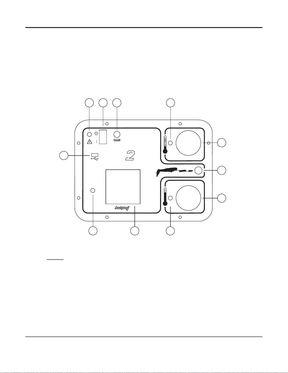
Status: Approved Doc#: AW10001726 Effective Date: nulldate
Abschnitt I - Beschreibung der Funktionen
In diesem Handbuch wird der Betrieb des GENIUS 2-Prüfgeräts/Kalibrators beschrieben. Dieses Gerät dient zum Überprüfen der
Genauigkeit des GENIUS 2-Ohrthermometers und zur automatischen Neukalibrierung, falls erforderlich. Außerdem kann mit
dem GENIUS 2-Prüfgerät/Kalibrator ein Testbericht für jedes getestete Thermometer erstellt und auf einem USB-Flash-Laufwerk
gespeichert werden. Das GENIUS 2-Prüfgerät/Kalibrator kann für alle Softwareversionen der GENIUS 2-Thermometer verwendet
werden.
Das GENIUS 2-Prüfgerät/Kalibrator enthält zwei unabhängig kontrollierte Infrarot-Kalibrierungsziele, ähnlich den werkseitigen
Kalibrierungszielen. Diese „Schwarzstrahler“-Ziele sind so konzipiert, dass sie einen ezienten Strahlungsübergang der Wärme
aufweisen und Infrarotstrahlung produzieren, die das menschliche Ohr mit Temperaturen von 32,2° C und 40,6° C nachempndet.
1 2 3 4
F 3.15A 250V
11
GENIUS
™
F/C˚
Checker / Calibrator
™
F/C˚
8 910
Abbildung 1 – Anordnung auf dem vorderen Bedienfeld
Legende
1 Netzanschluss 7 Hochtemperaturziel
2 Netzschalter 8 LED für Hochtemperaturziel
3 Sicherungen 9 LCD-Anzeige
4 LED für Niedertemperaturziel 10 Encoder-Knopf
5 Niedertemperaturziel 11 USB-Schnittstelle
6 Anschluss für GENIUS 2-Thermometer
5
6
7
GENIUS™ 2-Prüfgerät/Kalibrator
1
10/23/2008 Artwork#s: WN 182563-01 Job#: 16245
Benutzer- und Service-Handbuch
Page 31

Status: Approved Doc#: AW10001726 Effective Date: nulldate
Abschnitt II - Vorsichtsmaßnahmen und Warnhinweise
• Das GENIUS 2-Prüfgerät/Kalibrator muss gemäß der Anleitung in diesem Handbuch betrieben werden. Wenn das Gerät nicht
entsprechend den Anweisungen in diesem Handbuch eingesetzt wird, kann dies die Schutzfunktion der Sicherheitseinrichtungen
im GENIUS 2-Prüfgerät/Kalibrator beeinträchtigen.
• Das Gehäuse des GENIUS 2-Prüfgeräts/Kalibrators ist nicht wasserdicht. Achten Sie darauf, dass keine Flüssigkeit auf das
Bedienfeld des Geräts gelangt. Zudem liegt Wechselspannung am GENIUS 2-Prüfgerät/Kalibrator an. Achten Sie darauf, dass keine
Flüssigkeit mit der Außenfläche des Geräts in Berührung kommt, solange dieses an das Stromnetz angeschlossen ist.
• Die Oberflächenqualität an den Innenseiten der Schwarzstrahler-Referenzziele ist von kritischer Bedeutung für ihren Betrieb als
effiziente Infrarotstrahler. Achten Sie bei Arbeiten in der Nähe der Öffnung zu den Schwarzstrahler-Zielen sorgfältig darauf, die
Oberfläche innerhalb der Gummiklappen nicht zu berühren.
• Durchgebrannte Sicherungen müssen durch Sicherungen ersetzt werden, die in Nennspannung, Strom und Formfaktor genau
den Angaben im Abschnitt „Spezifikationen für das GENIUS 2-Prüfgerät/Kalibrator“ entsprechen. Trennen Sie das Gerät von der
Spannungsversorgung, bevor Sie eine durchgebrannte Sicherung austauschen.
• Dieses Gerät darf nicht in Gegenwart entzündlicher Anästhetika eingesetzt werden. In Gegenwart dieser Anästhetika besteht
Explosionsgefahr.
• Dieses Gerät enthält keine vom Benutzer zu wartenden Komponenten. Nehmen Sie die Frontplatte nicht ab. Lassen Sie
Wartungsarbeiten von qualifizierten Servicetechnikern durchführen.
• Verwenden Sie mit diesem Gerät nur das mitgelieferte Netzteil.
• Nach der Aufforderung, das GENIUS 2-Thermometer in eines der Schwarzstrahler-Ziele einzuführen, haben Sie dafür 60 Sekunden
Zeit. Wird dieses Zeitfenster überschritten, wird der Vorgang beendet.
• Vergewissern Sie sich vor dem Prüfen/Kalibrieren eines GENIUS 2-Thermometers, dass die Thermometerlinse sauber ist. Durch
sorgfältiges Reinigen wird sichergestellt, dass die Kalibrierungstoleranzen korrekt überprüft werden. Anleitungen zum Reinigen
finden Sie im Benutzerhandbuch des GENIUS 2-Thermometers.
• Verwenden Sie beim Anbringen einer GENIUS 2-Messhülse auf der Spitze des GENIUS 2-Thermometers nur Hülsen, die sich in einer
Kassette befinden. Fassen Sie die Messhülsen möglichst nicht an, um ungenaue Messwerte zu vermeiden. Messhülsen dürfen
nicht wiederverwendet werden. Verwenden Sie nur GENIUS 2-Messhülsen.
• Lassen Sie vor der Verwendung das GENIUS 2-Prüfgerät/Kalibrator nach dem Einschalten mindestens 15 Minuten aufwärmen.
Geben Sie den GENIUS 2-Thermometern, Messhülsen und dem GENIUS 2-Prüfgerät/Kalibrator genügend Zeit, sich an die
Raumtemperatur anzupassen, bevor Sie fortfahren. Liegt die Ausgangstemperatur nahe dem zulässigen Grenzwert der
Umgebungstemperatur, sollten Sie dem Gerät und den Thermometern eine längere Aufwärmphase zugestehen. Dadurch,
dass das GENIUS 2-Prüfgerät/Kalibrator tragbar ist, können Sie es an einen Ort umplatzieren, der den Anforderungen an die
Umgebungstemperatur gerecht wird.
• Um die elektromagnetische Verträglichkeit (EMV) zu gewährleisten, ein USB-Flash-Laufwerk verwenden, das das CE-Kennzeichen
trägt und der Norm EN55022 entspricht.
• Legen Sie das GENIUS 2-Thermometer niemals auf die Oberfläche des GENIUS 2-Prüfgeräts/Kalibrators oder lassen es dort liegen.
Die Thermosensoren im Innern der Sondenspitze des Thermometers erfassen die Wärme, die von den Schwarzstrahler-Zielen über
die vordere Bedienfläche übertragen wird. Hierdurch werden die Thermometersensoren instabil und es kommt zu fehlerhaften
Temperaturmessergebnissen.
• Das GENIUS 2-Prüfgerät/Kalibrator darf nur in geschlossenen Räumen ohne Zugluft und ohne große Schwankungen der
Umgebungstemperatur eingesetzt werden.
• Die USB-Schnittstelle vorne am Gerät ist nur für den Einsatz eines USB-Flash-Speicherlaufwerks vorgesehen. In die USBSchnittstelle dürfen keine anderen USB-Geräte eingesteckt werden. Das USB-Flash-Speicherlaufwerk ist vor dem Einschalten des
Geräts zu installieren.
• Falls das GENIUS 2-Prüfgerät/Kalibrator fallen gelassen wird, lassen Sie es im Werk neu kalibrieren.
GENIUS™ 2-Prüfgerät/Kalibrator
2
10/23/2008 Artwork#s: WN 182563-01 Job#: 16245
Benutzer- und Service-Handbuch
Page 32

SN
Status: Approved Doc#: AW10001726 Effective Date: nulldate
Abschnitt III - Symbolerläuterung
F/C˚
F/C˚
Seriennummer
Siehe Begleitdokumente
Standby-Betrieb
Hersteller
Herstellungsdatum
Doppelte oder
verstärkte Isolierung
Durch eine Sicherung mit
derselben Nennspannung
CE-Zeichen
ersetzen
USB-Schnittstelle Als Elektro- und
Elektronik-Altgerät
entsorgen
Hochtemperaturziel
Angaben zur UL-Liste
LISTED
(LABORATORY EQUIPMENT)
46EA
Niedertemperaturziel
Vorsicht: Nur für
den Gebrauch in
geschlossenen
GENIUS
Räumen vorgesehen
2-Thermometeranschluss
™
Das Infrarot-Ohrthermometer GENIUS 2 ist ein verlässlich und genau arbeitendes Temperaturmessgerät. Die Genauigkeit des
GENIUS 2-Thermometers liegt in seinem Design, den kontrollierten Kalibrierungsmethoden und den strikten Fertigungskontrollen
begründet. Eines der wichtigsten Funktionselemente von Thermometern ist die von Tyco Healthcare/Kendall hergestellte
ACCUSYSTEM√-Messhülse. Die GENIUS 2 Thermometer-ACCUSYSTEM√-Messhülse dient nach ihrer Platzierung auf einem GENIUS
2-Thermometer als Infektionsschutz zwischen Patient und Gerät sowie als Medium für die Wärmeübertragung vom Patienten zum
Thermometer. Die Funktionalität der GENIUS 2 Thermometer-ACCUSYSTEM√-Messhülse ist von größter Bedeutung für die Verhütung
von Gerätekontaminationen sowie auch für die Durchführung genauer Temperaturmessungen beim Patienten.
Das Infrarot-Ohrthermometer GENIUS 2 und die GENIUS 2 Thermometer-ACCUSYSTEM√-Messhülsen erfüllen die Erwartungen
unserer Kunden durch die Integration dieser beiden Komponenten während des Herstellungsprozesses. Die Parameter des
Formverfahrens für die GENIUS 2 Thermometer-ACCUSYSTEM√-Messhülsen werden von Tyco Healthcare/Kendall strengstens
überwacht, um Schwankungen zu minimieren und einheitliche und zuverlässige Produkte zu gewährleisten. Auch die speziellen
Thermoplastgüteklassen werden strikt kontrolliert; sie wurden speziell im Hinblick auf die Gewährleistung einheitlicher
Temperaturmessungen mit GENIUS 2-Thermometern gewählt. Die werkseitige Kalibrierung und die Endabnahme eines akzeptablen
GENIUS 2-Thermometers sind abhängig vom Einsatz akzeptabler GENIUS 2 Thermometer ACCUSYSTEM√-Messhülsen von Tyco
Healthcare/Kendall. Der Gebrauch generischer Messhülsen oder sonstiger, nicht von Tyco Healthcare/Kendall hergestellter
Messhülsen wird von Tyco Healthcare/Kendall weder unterstützt noch gebilligt. Der Gebrauch nicht genehmigter GENIUS 2
Thermometer-Messhülsen könnte die Genauigkeit des GENIUS 2-Thermometers gefährden. Zur Gewährleistung genauer
Temperaturmesswerte bei jedem Einsatz des Thermometers achten Sie bitte darauf, dass der Messhülsenkarton das ACCUSYSTEM√Logo aufweist.
GENIUS™ 2-Prüfgerät/Kalibrator
3
Benutzer- und Service-Handbuch
10/23/2008 Artwork#s: WN 182563-01 Job#: 16245
Page 33

Status: Approved Doc#: AW10001726 Effective Date: nulldate
Abschnitt IV - Erforderliche Geräte
1. GENIUS 2-Prüfgerät/Kalibrator
2. Netzteil mit Netzstecker
3. Meßsondenkabel
4. Bedienungsanleitung
5. Zu überprüfende GENIUS 2-Thermometer
6. GENIUS 2-Einweg-Messhülsen
7. Kleiner Kreuzschlitzschraubendreher
Abschnitt V – Systemeinrichtung
Führen Sie vor der Verwendung des GENIUS 2-Prüfgeräts/Kalibrators folgende Schritte durch:
1. Schließen Sie den AC-Steckeradapter für Ihr Land an das Netzteil an.
2. Verbinden Sie das Netzteil mit der Stromanschlussbuchse an der Vorderseite des Geräts.
3. Schließen Sie das Netzteil an eine Steckdose an.
4. Schalten Sie das Gerät mit dem Schalter auf dem Bedienfeld ein.
5. Lassen Sie das GENIUS 2-Prüfgerät/Kalibrator mindestens 15 Minuten lang warmlaufen.
6. Legen Sie eine Kassette mit neuen GENIUS 2-Messhülsen bereit.
7. Geben Sie den GENIUS 2-Thermometern Zeit, sich an die Raumtemperatur anzupassen.
8. Bereiten Sie die GENIUS 2-Thermometer durch gründliche Reinigung der Linsen vor. Anleitungen zum Reinigen nden Sie im
Benutzerhandbuch des GENIUS 2-Thermometers.
9. Entfernen Sie den Deckel des Batteriefachs mit einem kleinen Kreuzschlitzschraubendreher. Nehmen Sie die drei AAA-Batterien
heraus.
10. Schließen Sie den runden Sondenkabelanschluss auf der Vorderseite des GENIUS 2-Prüfgeräts/Kalibrators an.
11. Schließen Sie das andere Ende des Sondenanschlusses im Batteriefach an. Das Anschlussstück rastet im Batteriefach ein. Siehe
Abbildung 2.
Abbildung 2 – Einstecken des Sondenanschlusses in das Batteriefach des GENIUS 2-Thermometers
GENIUS™ 2-Prüfgerät/Kalibrator
10/23/2008 Artwork#s: WN 182563-01 Job#: 16245
4
Benutzer- und Service-Handbuch
Page 34

Status: Approved Doc#: AW10001726 Effective Date: nulldate
Abschnitt VI - Betrieb
Das folgende Verfahren beschreibt die für den Betrieb des GENIUS 2-Prüfgeräts/Kalibrators notwendigen Schritte. Es empehlt sich,
bei der Kalibrierungsprüfung der ersten Thermometer diesen Abschnitt des Handbuchs zur Hand zu haben, um sich schneller mit
dem Gerät vertraut zu machen.
Installation des USB-Flash-Laufwerks (Optional)
Installieren Sie an der USB-Schnittstelle am vorderen Bedienfeld ein USB-Flash-Laufwerk, wenn Sie möchten, dass eine Berichtsdatei
auf das USB-Flash-Laufwerk geschrieben wird. Wenn das USB-Flash-Laufwerk nach Durchführung einer Kalibrierungsprüfung
installiert wird, wird u. U. bei dem Versuch, die Berichtsdatei zu schreiben, eine Fehlermeldung angezeigt, wenn der Bediener nicht
wartet, bis das USB-Flash-Laufwerk seine Initialisierung beendet hat. Wenn das GENIUS 2-Prüfgerät/Kalibrator ausgeschaltet wird,
wird der gesamte interne Speicher (der noch nicht auf dem USB-Flash-Laufwerk gespeichert wurde) gelöscht.
Anlegen der Spannungsversorgung
Stellen Sie sicher, dass der Netzstecker am einen Ende des Netzteils in eine geerdete Steckdose eingesteckt ist. Schließen Sie
das Netzteil an die Stromanschlussbuchse auf der Vorderseite des Geräts an. Schalten Sie die Spannungsversorgung des GENIUS
2-Prüfgeräts/Kalibrators ein, indem Sie an der Vorderseite des Geräts den Netzschalter betätigen.
Startbildschirm
Der erste Bildschirm auf der LCD-Anzeige ist der Initialisierungsbildschirm, der die Softwareversion des GENIUS 2-Prüfgeräts/
Kalibrators und deren Datum anzeigt. Tritt bei der Initialisierung ein internes Problem auf, wird ein Fehlerbildschirm angezeigt (siehe
Abschnitt VII).
Erinnerungsbildschirm
Der nächste Bildschirm auf der LCD-Anzeige enthält eine Erinnerung daran, dass das GENIUS 2-Prüfgerät/Kalibrator nach dem
Einschalten mindestens 15 Minuten lang warmlaufen muss. Dadurch können die Infrarot-Schwarzstrahler-Ziele die richtige
Temperatur erreichen. Um diesen Bildschirm auszublenden, drücken Sie den Encoder-Knopf.
Hauptmenü
Anschließend wird der Bildschirm mit dem Hauptmenü angezeigt. Dieser Bildschirm enthält vier Menüoptionen:
Kalibrierung überprüfen
Einstellungen
Benutzer-/Standort-Daten einstellen
Uhrzeit/Datum einstellen
Um eine der Menüoptionen aufzurufen, verwenden Sie den Encoder-Knopf, indem Sie zu der Option blättern, sie markieren und
dann den Encoder-Knopf drücken.
Einstellungen
Das Menü „Einstellungen“ dient zum Einstellen der Sprachoption. Drücken Sie den Encoder-Knopf, um den Bildschirm zur
Sprachauswahl aufzurufen.
Sprachauswahl
Der Sprachauswahlbildschirm listet die für den Text auf dem LCD-Bildschirm verfügbaren Sprachen auf. Um eine Sprache auswählen,
verschieben Sie die Auswahlmarkierung zum gewünschten Eintrag, so dass dieser markiert ist. Drücken Sie den Encoder-Knopf,
um die Auswahl vorzunehmen und zum Hauptmenübildschirm zurückzukehren. Die gewählte Sprache wird in den permanenten
Speicher geschrieben und auch beim nächsten Einschalten des Geräts wieder verwendet.
Benutzer-/Standort-Daten einstellen
Im Bildschirm „Benutzer-/Standort-Daten einstellen“ werden der Name des Anwenders, die Organisation und/oder
Standortinformationen eingegeben. Diese Angaben werden in die Testberichtdatei geschrieben.
GENIUS™ 2-Prüfgerät/Kalibrator
10/23/2008 Artwork#s: WN 182563-01 Job#: 16245
5
Benutzer- und Service-Handbuch
Page 35

Status: Approved Doc#: AW10001726 Effective Date: nulldate
Zur Eingabe der Informationen blättern Sie mit dem Encoder-Knopf durch das Alphabet bis zum gewünschten Buchstaben im
Anwendernamen bzw. der Standortinformation. Wenn Sie den richtigen Buchstaben erreicht haben, drücken Sie den Encoder-Knopf,
um den Buchstaben auszuwählen, und fahren Sie mit dem nächsten Buchstaben fort. Zur Eingabe eines Leerzeichens drücken Sie
einfach den Encoder-Knopf, wenn an der Zeichenposition ein Leerzeichen oder Leerbuchstabe angezeigt wird. Der Benutzername
darf aus maximal 20 Buchstaben bestehen. Blättern Sie mit dem Encoder-Knopf zum Feld „Organisation“ und geben Sie nach
derselben Methode einen Namen für den Standort ein. Um das Menü zu beenden, blättern Sie zum Eintrag „FERTIG“ und drücken
den Encoder-Knopf.
Uhrzeit/Datum einstellen
Die Menüoption „Uhrzeit/Datum einstellen“ dient zum Einstellen des Datums und der Uhrzeit, die auf dem Testbericht angegeben
werden. Datum und Uhrzeit werden intern gespeichert und beim Einschalten des Geräts automatisch aktualisiert.
Zur Eingabe der Uhrzeit wählen Sie die entsprechenden Zahlen für Stunden und Minuten mit dem Encoder-Knopf aus. Hinweis: Die
Stundenangabe wird im 24-Stunden-Format eingegeben, so dass 1 Uhr mittags beispielsweise als 13:00 eingegeben werden muss.
Wenn der richtige Wert gewählt wurde, drücken Sie den Encoder-Knopf, um zum nächsten Feld der Uhrzeit und anschließend zum
Datumsfeld zu gelangen. Das Datum wird im Format MMTTJJJJ eingegeben. Wenn Sie nach der Eingabe der letzten Datumszier den
Encoder-Knopf drücken, verlassen Sie dieses Menü und kehren zum Hauptmenü zurück. Hinweis: Uhrzeit und Datum werden am
unteren Rand des Hauptmenüs angezeigt.
Kalibrierung überprüfen
Mit dieser Menüoption wird die Kalibrierungsprüfung eines GENIUS 2-Thermometers durchgeführt und das Thermometer, falls nötig,
automatisch neu kalibriert, wobei schrittweise eine Reihe von Bildschirmen angezeigt werden. Vergewissern Sie sich vor der Eingabe
dieser Menüoption, dass die in Abschnitt IV genannte erforderliche Ausrüstung verfügbar ist. Dazu gehört u. a. eine Kassette mit
unbenutzten (neuen) Messhülsen.
Schritt 1:
Aufwärmen der Infrarot-Schwarzstrahler-Ziele. Dieser Bildschirm wird angezeigt, während die Ziele auf die richtige Temperatur
geprüft werden. Sowohl das Nieder- als auch das Hoch-Ziel werden überprüft. Wenn sie die richtige Temperatur haben, zeigt der
Bildschirm für jedes Ziel „OK“ an. Sie werden aufgefordert, den Encoder-Knopf zu drücken, um zum nächsten Bildschirm zu gelangen.
Erreicht eines der beiden Ziele nicht die richtige Temperatur, wird ein Bildschirm mit einer Fehlermeldung angezeigt. Überprüfen
Sie in diesem Fall, dass das GENIUS 2-Prüfgerät/Kalibrator im korrekten Umgebungstemperaturbereich (Raumtemperatur) liegt und
nach dem Einschalten mindestens 15 Minuten lang warmlaufen konnte.
Schritt 2:
Inspizieren Sie das zu testende GENIUS 2-Thermometer. Stellen Sie sicher, dass die Thermometerlinse nicht verkratzt ist und keine
Verunreinigungen durch Ohrenschmalz und/oder andere Substanzen aufweist. Ist die Thermometerlinse verschmutzt, säubern Sie
sie gemäß den Anleitungen im Benutzerhandbuch des GENIUS 2-Thermometers. Wenn die Thermometerlinse sauber ist, verbinden
Sie das GENIUS 2-Thermometer mit dem Prüfgerät/Kalibrator, indem Sie das runde Ende des Thermometer-Schnittstellenkabels
in die runde Anschlussbuchse auf der Vorderseite des GENIUS 2-Prüfgeräts/Kalibrators stecken (siehe Abbildung 3). Önen Sie das
Batteriefach des Thermometers mit einem kleinen Kreuzschlitzschraubendreher. Nehmen Sie die Batterien heraus und legen Sie sie
zur Seite. Schließen Sie das andere Ende des Thermometersondenkabels im Batteriefach an und achten Sie dabei darauf, dass der
Stecker richtig einrastet. Siehe Abbildung 2 in Abschnitt V.
Hinweis: Für jedes Einstecken in ein Ziel muss eine neue Messhülse verwendet werden. Fingerspuren auf benutzten
Messhülsen oder wiederverwendete Messhülsen, die von einem Ziel des GENIUS 2-Prüfgeräts/Kalibrators
erhitzt wurden, können zu falschen Messergebnissen und folglich dem Fehlschlagen der Kalibrierungsprüfung oder
Neukalibrierung führen. Daher ist es von größter Wichtigkeit, jedes Mal eine neue Messhülse zu verwenden.
Schritt 3:
Drücken Sie zum Fortfahren den Encoder-Knopf und bringen Sie eine neue GENIUS 2-Messhülse auf dem GENIUS 2-Thermometer
an. Achten Sie darauf, dass Sie eine Hülse aus einer Kassette verwenden. Wenn Sie die Hülse auf dem Thermometer angebracht
haben, dürfen Sie die Sondenspitze nicht auf einen Gegenstand (einschließlich Hände, Finger und LCD-Anzeige) richten, da dies zu
falschen Temperaturmesswerten führt. Überprüfen Sie die Messhülse, um sicherzustellen, dass sie richtig sitzt (dass es zwischen
der Hülse und der Spitze keinen Zwischenraum gibt) und dass der Plastiklm keine Löcher, Risse oder Falten aufweist. Führen Sie
die mit der Hülse versehene Sondenspitze in das Niedertemperaturziel ein, neben dem eine LED-Anzeige blinkt. Stellen Sie sicher,
dass sich die Sondenspitze vollständig im Zielschacht bendet. Das richtige Einführen wird in Abbildung 3 dargestellt. Um einen
Zeitüberschreitungsfehler zu vermeiden, müssen Sie die umhüllte Sondenspitze innerhalb von 60 Sekunden nach Drücken des
Encoder-Knopfes in das Ziel einführen.
GENIUS™ 2-Prüfgerät/Kalibrator
10/23/2008 Artwork#s: WN 182563-01 Job#: 16245
6
Benutzer- und Service-Handbuch
Page 36

Status: Approved Doc#: AW10001726 Effective Date: nulldate
™
GENIUS
F
º
C
º
™
F/C˚
™
GENIUS
Checker / Calibrator
F/C˚
Abbildung 3 – Richtiges Einführen der GENIUS 2-Sondenspitze in das Ziel
Schritt 4:
Das Einführen der Sondenspitze in das Ziel wird automatisch erkannt und der Bildschirm zeigt nun die Anweisung „Scan-Taste
des GENIUS 2-Thermometers drücken“ an. Drücken Sie die Scan-Taste auf dem GENIUS 2-Thermometer, während dieses in das
Niedertemperaturziel eingeführt ist. Das GENIUS 2-Thermometer erzeugt drei kurze Signaltöne, während es die Temperatur des
Schwarzstrahler-Ziels misst. Nach der Temperaturmessung wird der nächste Bildschirm angezeigt.
Schritt 5:
Ziehen Sie das Thermometer aus dem Niedertemperaturziel und werfen Sie die Messhülse ab. Die Bildschirmanzeige ändert sich
nun zu „Eine neue Messhülse aufsetzen, dann GENIUS 2 in Hoch-Ziel einführen“. Verwenden Sie auch jetzt wieder eine neue GENIUS
2-Messhülse aus der Kassette und richten Sie die Sondenspitze nicht auf einen Gegenstand (einschließlich der Hände, Finger und
des LCD-Displays). Überprüfen Sie die Messhülse, um sicherzustellen, dass sie richtig sitzt (dass es zwischen der Hülse und der Spitze
keinen Zwischenraum gibt) und dass der Plastiklm keine Löcher, Risse oder Falten aufweist. Führen Sie die mit der Hülse versehene
Sondenspitze in das Hochtemperaturziel ein, neben dem eine LED-Anzeige blinkt. Stellen Sie sicher, dass sich die Sondenspitze
vollständig im Zielschacht bendet.
Schritt 6:
Das Einführen der Sondenspitze in das Hochtemperaturziel wird automatisch erkannt und der Bildschirm zeigt nun die Anweisung
„Scan-Taste des GENIUS 2-Thermometers drücken“ an. Drücken Sie die Scan-Taste auf dem GENIUS 2-Thermometer, während dieses
in das Hochtemperaturziel eingeführt ist. Das GENIUS 2-Thermometer erzeugt drei kurze Signaltöne, während es die Temperatur des
Schwarzstrahler-Ziels misst. Nach der Temperaturmessung wird der nächste Bildschirm angezeigt.
Schritt 7:
Wenn das GENIUS 2-Thermometer innerhalb der festgelegten Genauigkeitsgrenzen liegt, wird ein Ergebnisbildschirm mit der
Seriennummer des Thermometers und dem Hinweis angezeigt, dass das Thermometer die Kalibrierungsprüfung bestanden hat.
Wenn das GENIUS 2-Thermometer außerhalb der festgelegten Genauigkeitsgrenzen liegt, wird dem Benutzer angezeigt, dass
das GENIUS 2-Prüfgerät/Kalibrator nun eine Kalibrierungssequenz aufruft, bei der der Benutzer die Schritte 3 bis 6 noch dreimal
wiederholen muss, um Kalibrierungsdaten zu erfassen. Nach dem letzten Durchlaufen der Schritte 3 bis 6 versucht das GENIUS
2-Prüfgerät/Kalibrator, das GENIUS 2-Thermometer neu zu kalibrieren. Bei erfolgreicher Kalibrierung wird ein Ergebnisbildschirm
mit der Seriennummer des Thermometers und dem Hinweis angezeigt, dass das Thermometer die Kalibrierung bestanden hat. Wenn
die Neukalibrierung nicht erfolgreich ist oder das Thermometer nicht kalibriert werden kann, wird ein Ergebnisbildschirm mit der
GENIUS™ 2-Prüfgerät/Kalibrator
7
10/23/2008 Artwork#s: WN 182563-01 Job#: 16245
Benutzer- und Service-Handbuch
Page 37

Status: Approved Doc#: AW10001726 Effective Date: nulldate
Seriennummer des Thermometers und dem Hinweis angezeigt, dass die Kalibrierung des Thermometers gescheitert ist.
Schritt 8:
Nachdem der Ergebnisbildschirm mit dem Bestehen/Fehlschlagen der Kalibrierung angezeigt wurde, drücken Sie den EncoderKnopf, um einen zweiten Ergebnisbildschirm mit den Zieltemperaturen, den GENIUS 2-Messwerten und den Abweichungen
zwischen Ziel und Thermometer aufzurufen.
Schritt 9:
Der nächste Bildschirm enthält die Frage „Bericht auf USB-Flash-Laufwerk schreiben?“ und darunter die Antwortmöglichkeiten
„Ja“ und „Nein“. Wenn Sie einen Bericht benötigen, stecken Sie ein Flash-Laufwerk in die USB-Schnittstelle auf dem Bedienfeld
ein. Hinweis: Warten Sie nach dem Einstecken etwa 30 Sekunden, bis das USB Flash-Laufwerk initialisiert wurde. Blättern Sie mit
dem Encoder-Knopf zu „Ja“ bzw. „Nein“ und treen Sie Ihre Auswahl durch Drücken des Knopfes. Bei Auswahl von „Nein“ kehren
Sie zum Hauptmenü zurück. Bei Auswahl von „Ja“ wird ein Bericht auf das USB-Flash-Laufwerk geschrieben. Die Datei erhält die
Seriennummer des Thermometers als Dateiname und .TXT als Dateinamenerweiterung. Die Datei enthält die Testergebnisse sowie
andere Informationen wie Seriennummer, Datum, Uhrzeit, Anwendername und Organisation. Diese Datei ist eine einfache ASCIITextdatei, die nur in Englisch vorliegt. Diese Datei kann mit Microsoft™ Windows-Programmen wie dem Editor geönet und zu
einem Drucker übertragen werden. Wenn die Datei geschrieben wurde, wird auf dem Bildschirm die Anweisung „Zum Fortfahren
Knopf drücken“ angezeigt. Drücken Sie den Encoder-Knopf, um zum Hauptmenü zurückzukehren.
Schritt 10:
Nach der Durchführung einer Kalibrierungsprüfung/Neukalibrierung entfernen Sie den Sondenanschluss aus dem Batteriefach,
indem Sie ihn etwas hin- und herbewegen. Legen Sie dann die drei AAA-Batterien wieder ein (achten Sie dabei auf die richtige
Polarität). Bringen Sie den Batteriefachdeckel wieder an und schrauben Sie ihn fest.
Schritt 11:
Entfernen Sie das USB-Flash-Laufwerk, bevor Sie den Deckel des Gehäuses schließen. Der Deckel muss geschlossen sein, solange das
GENIUS 2-Prüfgerät/Kalibrator nicht in Gebrauch ist.
Abschnitt VII - Fehlermeldungen
Die Fehlermeldungen tragen eine Nummer, wie etwa „Fehler 1“ usw. Im Folgenden nden Sie eine Erläuterung der Fehler:
Fehler 1: Interner Fehler
Dieser Fehler weist auf ein Problem im GENIUS 2-Prüfgerät/Kalibrator hin. Besteht der Fehler auch nach dem Aus- und
Einschalten des Geräts weiterhin, schicken Sie es zum Service ins Werk ein.
Fehler 2: Kommunikation mit dem GENIUS 2-Thermometer nicht möglich.
Diese Fehlermeldung zeigt an, dass die Kommunikation zwischen dem GENIUS 2-Thermometer und dem GENIUS 2-Prüfgerät/
Kalibrator entweder nicht stattndet oder fehlerhaft ist. Überprüfen Sie beide Enden des Thermometer-Sondenkabels und
besonders das Ende, das im Batteriefach einsteckt wird. Die Stifte des Thermometer-Sondenkabels rasten möglicherweise
nicht richtig ein, wenn sie verbogen oder beschädigt werden. Führen Sie nach der Überprüfung des Sondenkabels einen
erneuten Versuch der Kalibrierungsprüfung durch. Besteht das Problem weiterhin, schließen Sie zur Probe ein anderes GENIUS
2-Thermometer an (sofern verfügbar). Besteht das Problem weiterhin, schicken Sie das Gerät mit dem Thermometerkabel und
dem GENIUS 2-Thermometer, bei dem dieser Fehler auftrat, zum Service ins Werk ein.
Fehler 3: Zeitüberschreitung
Dieser Fehler zeigt an, dass der Anwender zu lange für die Durchführung eines Vorgangs gebraucht hat. Dieser Fehler kann
beim Anschließen des GENIUS 2-Thermometers oder beim Anbringen einer Messhülse auf dem Thermometer auftreten. Die
Zeitüberschreitung ist auf eine Minute eingestellt. Führen Sie den Vorgang, der den Fehler verursachte, erneut durch.
Fehler 4: Ziel außerhalb des gültigen Bereichs
Dieser Fehler zeigt an, dass eines der Schwarzstrahler-Ziele außerhalb des zulässigen Temperaturbereichs liegt. Überprüfen Sie,
dass das Gerät innerhalb des zulässigen Umgebungstemperaturbereichs betrieben wird. Siehe Abschnitt VIII. Tritt der Fehler
auch bei einem Betrieb innerhalb der festgelegten Umgebungstemperaturbedingungen weiterhin auf, sind möglicherweise die
Schwarzstrahler-Ziele defekt. Schicken Sie das Gerät zum Service ins Werk ein.
GENIUS™ 2-Prüfgerät/Kalibrator
8
10/23/2008 Artwork#s: WN 182563-01 Job#: 16245
Benutzer- und Service-Handbuch
Page 38

Status: Approved Doc#: AW10001726 Effective Date: nulldate
Fehler 5: Fehler beim Schreiben auf das USB-Flash-Laufwerk
Diese Fehlermeldung weist auf ein Problem hin, das auftritt, wenn die Berichtsdatei auf ein USB-Flash-Speichergerät
geschrieben wird. Vergewissern Sie sich, dass der Schreibschutzschalter am USB-Laufwerk in der „Aus“-Position
steht. Überprüfen Sie, ob das Laufwerk über genügend freien Speicherplatz verfügt und dass die Sicherheits- und
Verschlüsselungsfunktionen deaktiviert sind.
Fehler 6: Umgebungstemperatur außerhalb des gültigen Bereichs
Dieser Fehler zeigt an, dass die Umgebungstemperatur außerhalb des festgelegten Bereichs für eine exakte Neukalibrierung
liegt. Überprüfen Sie, dass das Gerät innerhalb des zulässigen Umgebungstemperaturbereichs betrieben wird. Siehe Abschnitt
VIII.
Fehler 7: Falsches Ziel
Dieser Fehler zeigt an, dass das GENIUS 2-Thermometer zu früh oder in das falsche Ziel eingeführt wurde. Achten Sie darauf, die
Anweisungen auf dem Bildschirm zu befolgen und Schritte erst dann durchzuführen, wenn die entsprechenden Anweisungen
angezeigt werden.
Diese Fehlermeldung wird 60 Sekunden lang angezeigt, bevor das Hauptmenü wieder aufgerufen wird. Um den Bildschirm mit
dieser Fehlermeldung früher auszublenden, drücken Sie den Encoder-Knopf.
Abschnitt VIII – Technische Daten des Prüfgeräts/Kalibrators
Temperatursollwerte
Niedertemp.-Ziel
. . . . . . . . . . . . . . . . . . . . . . . . . . . . . . . . . . . . . . . . . . . . . . . . . . . . . . . .32,2 °C +/- 0,3 °C
Hochtemp.-Ziel . . . . . . . . . . . . . . . . . . . . . . . . . . . . . . . . . . . . . . . . . . . . . . . . . . . . . . . . . .40,6 °C +/- 0,3 °C
Genauigkeit der Zieltemperatur
. . . . . . . . . . . . . . . . . . . . . . . . . . . . . . . . . . . . . . . . . . . . . . . . . . . . . . . . . . . . . . Nach dem 1. Jahr +/- 0,06 °C
. . . . . . . . . . . . . . . . . . . . . . . . . . . . . . . . . . . . . . Anfangsgrenzwert +/- 0,03 °C
Genauigkeit des GENIUS 2-Thermometers nach der Neukalibrierung*
Messwerte zwischen 36, 0 °C und 39,0 °C
. . . . . . . . . . . . . . . . . . . . . . . . . . . . . . . . . . . . . . . . . . . +/- 0,2 °C
Messwerte unter 36, 0 °C oder über 39,0°C . . . . . . . . . . . . . . . . . . . . . . . . . . . . . . . . . . . . . . . . . . +/- 0,3 °C
Aufwärmzeit vor der Verwendung . . . . . . . . . . . . . . . . . . . . 15 Minuten (von nicht extremen Umgebungswerten aus)
Umgebungstemperaturbereich für den Betrieb. . . . . . . . . . . . . . . . . . . . . . . . . . . . . . . . . . . . . 21,1 - 26,7 °C
Bereich der relativen Luftfeuchtigkeit für den Betrieb
. . . . . . . . . . . . . . . . . . . .50 +/- 20 %, nicht kondensierend
Höhenbereich . . . . . . . . . . . . . . . . . . . . . . . . . . . . . . . . . . . . . . . . . . . . . . . . . . . . . . . . . . .Bis zu 2000 Meter
Lagertemperaturbereich . . . . . . . . . . . . . . . . . . . . . . -25 °C - 55 °C, 85 % relative Luftfeuchtigkeit, nicht kondensierend
Ungefähre Abmessungen
. . . . . . . . . . . . . . . . . . . . . . . . . . . . . . . . . . . . . . . . . . . . . . . . . . . . . . . . . . . . . . . . . . . . . . 31,1 cm
Länge
Tiefe . . . . . . . . . . . . . . . . . . . . . . . . . . . . . . . . . . . . . . . . . . . . . . . . . . . . . . . . . . . . . . . . . . . . . . 15,9 cm
Breite. . . . . . . . . . . . . . . . . . . . . . . . . . . . . . . . . . . . . . . . . . . . . . . . . . . . . . . . . . . . . . . . . . . . . . 26,0 cm
Gewicht . . . . . . . . . . . . . . . . . . . . . . . . . . . . . . . . . . . . . . . . . . . . . . . . . . . . . . . . . . . . . . . . . . . . . .3,3 kg
Spannungsversorgung. . . . . . . . . . . . . . . . . . . . . . . . . . . . . . . . . . . . . . . . . . . 100 - 240 V, 0,8 - 0,4 A, 47 - 63 Hz
Sicherungen . . . . . . . . . . . . . . . . . . . . . . . . . . . . . . . . . . . . . . . . . . . . . . Schurter FSF 5 x 20 mm, inke Sicherung
. . . . . . . . . . . . . . . . . . . . . . . . . . . . . . . . . . . . . . . . . . . . . . . . . . . . . . . . . . . 250 V, 3.15 A Ausschaltvermögen
Empfohlener Zeitabstand für die Kalibrierung des Prüfgeräts/Kalibrators. . . . . . . . . . . . . . . . . . . . . .Ein Jahr
ESD-Sicherheit . . . . . . . . . . . . . . . . . . . . . . . . . . . Erfüllt die Nichtdurchgängigkeitskriterien C der IEC-Norm 61000-4-2
Verschmutzungsgrad. . . . . . . . . . . . . . . . . . . . . . . . . . . . . . . . . . . . . . . . . . . . . . . . . . . . . . . . . . . . . . . 2
Installationskategorie. . . . . . . . . . . . . . . . . . . . . . . . . . . . . . . . . . . . . . . . . . . . . . . . . . . . . . . . . . . . . . II
. . . . . . . . . . . . . . . . . . . . . . . . . . . . . . . . . . . . . . . . . . . Nur für den Gebrauch in geschlossenen Räumen vorgesehen
* Nach einer Neukalibrierung mit dem GENIUS 2-Prüfgerät/Kalibrator entspricht die Genauigkeit möglicherweise nicht der werkseitigen Kalibrierung
GENIUS™ 2-Prüfgerät/Kalibrator
10/23/2008 Artwork#s: WN 182563-01 Job#: 16245
9
Benutzer- und Service-Handbuch
Page 39

Status: Approved Doc#: AW10001726 Effective Date: nulldate
Abschnitt IX – Reinigungsanleitung
VORSICHT: PRÜFGERÄT/KALIBRATOR, KABEL ODER NETZKABEL NICHT IN WASSER ODER SONSTIGE REINIGUNGSLÖSUNGEN EINTAUCHEN.
ZUM REINIGEN FEUCHTE (JEDOCH NICHT NASSE) TÜCHER VERWENDEN. WERDEN DIE HIER AUFGEFÜHRTEN REINIGUNGSVERFAHREN
NICHT EINGEHALTEN, KANN DIES DIE BENUTZER GEFÄHRDEN.
Wie bei allen mit Wechselstrom betriebenen Elektrogeräten ist zur Vermeidung von Stromschlägen, Brandgefahr oder Schäden an
den Elektrikbauteilen darauf zu achten, dass keine Flüssigkeit in das Prüfgerät/Kalibrator eintritt.
Allgemeine Hinweise zur Reinigung
Reinigen Sie das GENIUS 2-Prüfgerät/Kalibrator wie nachfolgend beschrieben:
• TRENNEN SIE ZUERST DAS NETZTEIL DES GENIUS 2-PRÜFGERÄTS/KALIBRATORS VOM STROMNETZ. REINIGEN SIE DAS GERÄT
NIEMALS, SOLANGE ES AN DAS STROMNETZ ANGESCHLOSSEN IST.
• Für allgemeine Reinigungsarbeiten an den Außenflächen ein mildes Reinigungsmittel verwenden. Sie können das Gerät auch
mit einem mit Isopropylalkohol angefeuchteten Tuch reinigen. KEINE Scheuer- oder Lösungsmittel verwenden. Vermeiden Sie
übermäßige Feuchtigkeit in der Nähe der Zieleinheiten und der elektrischen Anschlüsse.
• Reinigen Sie auf keinen Fall die Zieleinheiten unter den Gummiklappen.
• Reinigen Sie die Zielschächte oder -klappen nicht mit Alkohol.
Falls Zweifel bezüglich der Kompatibilität eines Reinigungsmittels mit einem Teil dieses Geräts oder seinen Materialien aufkommen,
wenden Sie sich bitte an den Kundendienst von Tyco Healthcare/Kendall (siehe Abschnitt XI).
Abschnitt X - Fehlersuche und -behebung
Nachfolgend werden einige gängige Probleme beschrieben:
Problem Mögliche Ursache Lösung
Das GENIUS 2-Prüfgerät/Kalibrator lässt sich
nicht einschalten
Testbericht wird nicht auf das USB-FlashLaufwerk geschrieben.
Neukalibrierung scheitert bei mehreren GENIUS
2-Thermometern
Beim Testen desselben GENIUS
2-Thermometers wird wiederholt der Fehler
6 angezeigt.
Das GENIUS 2-Thermometer zeigt nach einer
erfolgreichen Neukalibrierung anscheinend zu
hohe oder zu niedrige Messwerte an.
Das GENIUS 2-Prüfgerät/Kalibrator wird nicht mit Netzstrom versorgt. Überprüfen Sie, ob das Netzkabel richtig angeschlossen ist.
Sicherung durchgebrannt Wechseln Sie die Sicherung aus.
USB-Flash-Laufwerk nicht formatiert Formatieren Sie das Flash-Laufwerk mit einem PC oder Laptop.
USB-Flash-Laufwerk schreibgeschützt Deaktivieren Sie den Schreibschutz mit einem PC oder Laptop.
Nicht genügend freier Speicher auf dem USB-Flash-Laufwerk Löschen Sie nicht benötigte Objekte mit einem PC oder Laptop oder
USB-Flash-Laufwerk nicht kompatibel mit dem GENIUS 2-Prüfgerät/Kalibrator Verwenden Sie ein anderes USB-Flash-Speichergerät.
Das GENIUS 2-Prüfgerät/Kalibrator hatte nicht genug Zeit, um das neu
eingesteckte USB-Flash-Laufwerk zu erkennen.
In einem der Schwarzstrahler-Ziele ist eine Messhülse stecken gebliebe Entfernen Sie die Messhülse mit einer kleinen Pinzette oder Klemme aus dem
Messhülse verschmutzt Verwenden Sie für jede Messung eine neue Messhülse. Verwenden Sie
Thermometerlinse verschmutzt Reinigen Sie die Thermometerlinse gemäß den Anweisungen im GENIUS
GENIUS 2-Thermometer sitzt nicht richtig Stellen Sie sicher, dass das GENIUS 2-Thermometer vollständig und mit dem
GENIUS 2-Thermometer, Messhülse und/oder Prüfgerät/Kalibrator nicht bei
Raumtemperatur
Mögliches Stromversorgungsproblem des GENIUS 2-Thermometers Wiederholen Sie die Kalibrierungsprüfung/Neukalibrierung mit einem
Messhülse wurde bei der Kalibrierungsprüfung/Neukalibrierung wiederholt
verwendet.
verwenden Sie ein anderes USB-Flash-Speichergerät.
Führen Sie den Schreibvorgang erneut durch.
Schwarzstrahler-Ziel. Verkratzen Sie nicht die Innenfläche des Ziels
Messhülsen nicht mehrmals. Berühren Sie Messhülsen niemals mit der Hand.
2-Benutzerhandbuch.
richtigen Winkel im Ziel sitzt.
Geben Sie den GENIUS 2-Thermometern, Messhülsen und/oder dem
Prüfgerät/Kalibrator genügend Zeit, sich an die Raumtemperatur anzupassen,
bevor Sie fortfahren.
anderen GENIUS 2-Thermometer und schicken Sie das problematische
Thermometer zum Service ins Werk ein.
Führen Sie die Kalibrierungsprüfung/Neukalibrierung erneut durch und
verwenden Sie dabei vor jedem Einführen in ein Ziel eine neue Messhülse.
GENIUS™ 2-Prüfgerät/Kalibrator
10
10/23/2008 Artwork#s: WN 182563-01 Job#: 16245
Benutzer- und Service-Handbuch
Page 40

Status: Approved Doc#: AW10001726 Effective Date: nulldate
Abschnitt XI - Kundendienst
Das GENIUS 2-Prüfgerät/Kalibrator muss ein Mal pro Jahr im Werk kalibriert und geprüft werden. Informieren Sie Tyco Healthcare/
Kendall am oder vor dem Datum der Kalibrierung des Prüfgeräts/Kalibrators und schicken Sie das Gerät ein. Am Prüfgerät/Kalibrator
wird einen Monat vor dem Kalibrierungsdatum zur Erinnerung eine Meldung angezeigt.
VORSICHT: DAS GERÄT ENTHÄLT KEINE TEILE, DIE VOM ANWENDER GEWARTET WERDEN KÖNNEN. SCHICKEN SIE DAS GERÄT ZUM
SERVICE AN DAS WERK.
Sollte die Einsendung eines Geräts zur Reparatur erforderlich werden, beachten Sie bitte Folgendes:
1. Fordern Sie bei Tyco Healthcare/Kendall unter der nachfolgenden Adresse oder bei Ihrer Kundendienstvertretung vor Ort eine
Rücksendeauftragsnummer sowie Versandanweisungen an.
2. Bitte senden Sie das versicherte Paket an den vor Ort für Sie zuständigen Servicekontakt oder an eine der nachstehend
genannten Adressen.
USA Kanada Außerhalb der USA und Kanadas
Tyco Healthcare Group LP Tyco/Healthcare Canada Tyco Healthcare Group LP
98.6 Faichney Drive 7300 Trans Canada Highway Unit 2 Talisman Business Center, London Road
Watertown, NY 13601 Pointe-Claire, QC Bicester, OX26 6HR, UK
1-800-448-0190 oder H9R 1C7 +44-1869-328065
(315) 788-5246 1-877-664-8926 oder
(514) 695-1220
Teileliste
Für die nachstehend aufgeführten Ersatzteile wenden Sie sich bitte an das für Sie zuständige Kundendienstcenter oder den für Sie
zuständigen Vertreter.
Beschreibung
GENIUS 2-Prüfgerät/Kalibrator . . . . . . . . . . . . . . . . . . . . . . . . . . . . . . . . . . . . . . . . . . . . . . . . . . . . . . . . .303097
Technisch überholtes GENIUS 2-Prüfgerät/Kalibrator . . . . . . . . . . . . . . . . . . . . . . . . . . . . . . . . . . . . . . . . . . . . 303096
Abschnitt XII - Gewährleistung
Tyco/Healthcare leistet bei normalem Einsatz für einen Zeitraum von 1 Jahr ab dem Datum der Auslieferung durch Tyco Healthcare/
Kendall an den Erstkäufer Gewähr dafür, dass das GENIUS 2-Prüfgerät/Kalibrator keine Material- und Verarbeitungsfehler aufweist.
Die Haftung im Rahmen dieser Vereinbarung beschränkt sich auf die in einer Tyco Healthcare-Service-Einrichtung durchzuführende
Reparatur bzw. den Ersatz (nach Wahl von Tyco Healthcare/Kendall) aller Produkte, die nach Ermessen von Tyco Healthcare/Kendall
bei normalem Einsatz und Service Material- oder Verarbeitungsfehler aufweisen. Diese Gewährleistung erstreckt sich nicht auf den
Kauf von Produkten, die von anderen Einrichtungen bzw. Personen als Tyco Healthcare/Kendall bzw. dessen autorisierter Vertretung
repariert wurden oder die Missbrauch, Fahrlässigkeit oder Unfällen ausgesetzt waren oder die nicht gemäß den von Tyco Healthcare/
Kendall bereit gestellten Anweisungen verwendet wurden, und Tyco Healthcare/Kendall haftet nicht für Verluste in derartigem
Zusammenhang. Tyco Healthcare/Kendall übernimmt keinerlei Haftung mit Ausnahme der hier ausdrücklich gewährten und
autorisiert auch keinen Repräsentanten und keine sonstige Person zur Übernahme einer solchen Haftung.
Tyco Healthcare/Kendall LEHNT ALLE SONSTIGEN GEWÄHRLEISTUNGEN, OB AUSDRÜCKLICHER ODER IMPLIZIERTER ART AB, DARUNTER
AUCH ALLE IMPLIZITEN GEWÄHRLEISTUNGEN IN BEZUG AUF DIE HANDELSTAUGLICHKEIT ODER EIGNUNG FÜR BESTIMMTE ZWECKE
ODER ANWENDUNGEN, MIT AUSNAHME DER IN DER PRODUKTKENNZEICHNUNG AUSDRÜCKLICH GEMACHTEN ANGABEN. Tyco
Healthcare/Kendall HAFTET KEINESFALLS FÜR FOLGESCHÄDEN, INDIREKTE ODER SICH ERGEBENDE SCHÄDEN IN VERBINDUNG MIT DEM
KAUF ODER EINSATZ DIESES PRODUKTS.
GENIUS™ 2-Prüfgerät/Kalibrator
11
10/23/2008 Artwork#s: WN 182563-01 Job#: 16245
Benutzer- und Service-Handbuch
Page 41

Status: Approved Doc#: AW10001726 Effective Date: nulldate
Abschnitt XIII – Angaben zur elektromagnetischen Störfreiheit
Das GENIUS 2-Prüfgerät/Kalibrator wurde gemäß den Normen IEC/EN61010-1 und EN61326-1 gebaut und getestet.
Das Prüfgerät/Kalibrator wurde für die Verwendung in der unten angegebenen elektromagnetischen Umgebung konzipiert. Der
Benutzer des Geräts hat sicherzustellen, dass es in einem derartigen Umfeld eingesetzt wird.
Emissionstest Auflagenerfüllung Elektromagnetisches Umfeld – Leitlinien
Leitungs- und StrahlungsEmissionen (EN61326-1)
Harmonischer Strom
(EN61000-3-2)
Spannungsschwankungen und
Flimmern (EN61000-3-3)
Immunität gegen
Störausstrahlung (EN61000-4-3)
Immunität gegen
leitungsgeführte Störungen
(EN61000-4-6)
Immunität gegen
Stromfrequenzen-Magnetfelder
(EN61000-4-8)
Immunität gegen
Spannungsabfälle und
-unterbrechungen
(EN61000-4-11)
Gruppe 1, Klasse B Die Emissionen des Prüfgeräts/Kalibrators sind sehr schwach,
und es ist unwahrscheinlich, dass die Funktion von Geräten in
unmittelbarer Umgebung beeinträchtigt wird.
Klasse A
Erfüllt die Auagen
Erfüllt die Auagen
Erfüllt die Auagen
Erfüllt die Auagen
Erfüllt die Auagen
Immunität gegen schnelle
transiente elektrische Störgrößen/
Burst (EN61000-4-4)
Immunität gegen
Stoßspannungen (EN61000-4-5)
Elektrostatische Entladung
(EN61000-4-2)
GENIUS™ 2-Prüfgerät/Kalibrator
Erfüllt die Auagen
Erfüllt die Auagen
Erfüllt die Kriterien C,
nicht durchgehend
12
10/23/2008 Artwork#s: WN 182563-01 Job#: 16245
Benutzer- und Service-Handbuch
Page 42

Status: Approved Doc#: AW10001726 Effective Date: nulldate
Indice
Italiano
Pagina
Sezione I - Funzionamento .............................................................................................................................................................. 1
Sezione II – Precauzioni e avvertenze ........................................................................................................................................... 2
Sezione III — Identificazione dei simboli ..................................................................................................................................... 3
Sezione IV - Attrezzatura richiesta ................................................................................................................................................. 4
Sezione V - Impostazione del sistema ............................................................................................................................................ 4
Sezione VI - Procedura operativa .................................................................................................................................................... 5
Alimentazione ............................................................................................................................................................................... 5
Schermata di avvio ........................................................................................................................................................................ 5
Schermata Promemoria ................................................................................................................................................................. 5
Menu principale ............................................................................................................................................................................ 5
Preferenze ..................................................................................................................................................................................... 5
Selezione della lingua ................................................................................................................................................................... 5
Impostazione delle informazioni dell’utente/centro ..................................................................................................................... 5
Impostazione della data e dell’ora ................................................................................................................................................. 6
Controllo della calibrazione ........................................................................................................................................................... 6
Sezione VII - Messaggi di errore ......................................................................................................................................................8
Sezione VIII - Specifiche tecniche del sistema di controllo e calibrazione ................................................................................ 9
Sezione IX — Istruzioni per la pulizia .......................................................................................................................................... 10
Sezione X — Risoluzione dei problemi ....................................................................................................................................... 10
Sezione XI — Assistenza clienti .................................................................................................................................................... 11
Sezione XII — Garanzia.................................................................................................................................................................. 11
Sezione XIII — Dichiarazione di conformità elettromagnetica .............................................................................................. 12
Questo prodotto contiene un software di proprietà esclusiva di Tyco Healthcare Group LP. Tyco Healthcare Group LP concede all’utente
una licenza non esclusiva e limitata per l’impiego del software in conformità alle istruzioni di funzionamento. È possibile richiedere a Tyco
Healthcare Group LP una copia di tale licenza.
10/23/2008 Artwork#s: WN 182563-01 Job#: 16245
Page 43

Status: Approved Doc#: AW10001726 Effective Date: nulldate
Sezione I - Funzionamento
Questo manuale descrive il funzionamento del sistema di controllo della calibrazione/ calibratore GENIUS 2. Questo dispositivo è
stato sviluppato per controllare l’accuratezza
del termometro timpanico GENIUS 2 e ricalibrarlo automaticamente, se necessario. Inoltre il sistema di controllo della calibrazione/
calibratore GENIUS 2 è in grado di generare un report del test di ogni termometro controllato e di salvarlo su una chiavetta di
memoria USB. Il sistema di controllo della calibrazione/calibratore GENIUS 2 è compatibile con tutte le revisioni del software del
termometro GENIUS 2.
Il sistema di controllo della calibrazione/calibratore GENIUS 2 contiene due target di calibrazione a infrarossi controllati
indipendentemente, simili ai target di calibrazione di fabbrica. Questi “corpi neri”(target) sono stati progettati per ricevere un
trasferimento di calore radiante eciente e produrre una radiazione infrarossa simile all’orecchio umano alla temperatura di 32,2°C
(90,0°F ) e 40,6°C (105,0°F).
1 2 3 4
F 3.15A 250V
11
GENIUS
™
F/C˚
Checker / Calibrator
™
F/C˚
8 910
Figura 1 - Vista del pannello frontale
Legenda
1 Connettore di alimentazione 7 Target di temperatura alta
2 LED di accensione/spegnimento 8 LED del target di temperatura alta
3 Alloggiamento fusibile 9 Display LCD
4 LED del target di temperatura bassa 10 Manopola
5 Target di temperatura bassa 11 Porta USB
6 Connettore del termometro GENIUS 2
5
6
7
GENIUS™ 2
Sistema di controllo della calibrazione/calibratore
10/23/2008 Artwork#s: WN 182563-01 Job#: 16245
1
Manuale operativo e di manutenzione
Page 44

Status: Approved Doc#: AW10001726 Effective Date: nulldate
Sezione II - Precauzioni e avvertenze
• Il sistema di controllo della calibrazione/calibratore GENIUS 2 deve essere utilizzato come specificato in questo manuale; in caso
contrario si potrebbero danneggiare i suoi dispositivi di sicurezza.
• La struttura del sistema di controllo della calibrazione/calibratore GENIUS 2 non è impermeabile. Evitare di versare liquidi di
qualsiasi tipo sul pannello anteriore del dispositivo. Inoltre, poiché il sistema di controllo della calibrazione/calibratore GENIUS
2 è alimentato da una fonte di alimentazione c.a., evitare il possibile contatto tra i liquidi e la superficie esterna del dispositivo,
quando è collegato alla rete elettrica.
• La qualità della superficie interna dei corpi neri (target di riferimento) è critica per il loro funzionamento come efficienti radiatori a
infrarossi. Operare, pertanto, con cura nei pressi dell’entrata dei corpi neri target per evitare il contatto con la superficie all’interno
delle alette in gomma.
• Quando salta un fusibile, sostituirlo con uno corrispondente per tensione nominale, corrente e forma, come specificato nella
sezione Specifiche tecniche del sistema di controllo della calibrazione/calibratore GENIUS 2 in questo manuale. Prima di sostituire
il fusibile, verificare che il dispositivo sia scollegato dalla fonte di alimentazione c.a.
• Questo dispositivo non deve essere utilizzato in presenza di anestetici infiammabili, a causa del rischio di esplosione.
• Questo dispositivo non contiene componenti riparabili dall’operatore. Non rimuovere il pannello anteriore. Contattare il personale
di assistenza qualificato.
• Utilizzare solo il modulo di alimentazione fornito con questo dispositivo.
• Quando viene richiesto di inserire il termometro GENIUS 2 in uno dei corpi neri target, si ha a disposizione un periodo di 60 secondi
per eseguire questa azione. In caso di ritardo, la procedura viene terminata.
• Prima di eseguire il controllo della calibrazione del termometro GENIUS 2, verificare che la lente del termometro sia pulita. Una
corretta pulizia assicura che le tolleranze della calibrazione siano verificate adeguatamente. Fare riferimento alle istruzioni di
pulizia del manuale d’uso del termometro Genius 2.
• Quando si installa un coprisonda GENIUS 2 sulla punta del termometro GENIUS 2, utilizzare solo i coprisonda contenuti nella
cassetta. Non toccare con le mani i coprisonda, per evitare letture inaccurate. Non riutilizzare i coprisonda. Usare esclusivamente
coprisonda GENIUS 2.
• Dopo l’accensione, lasciar riscaldare il sistema di controllo della calibrazione/calibratore GENIUS 2 per almeno 15 minuti prima
dell’uso. Prima di procedere, accertarsi che i termometri GENIUS 2, i coprisonda e il sistema di controllo della calibrazione/
calibratore GENIUS 2 abbiano raggiunto la temperatura ambiente. Prolungare il periodo di ambientazione alla temperatura
qualora il dispositivo o i termometri siano stati conservati a temperature ambientali a limite di quelle consentite. La
trasportabilità del sistema di controllo della calibrazione/calibratore GENIUS 2 consente di trasferire il dispositivo in aree che
soddisfano i requisiti di temperatura ambiente.
• Al fine di mantenere la conformità alla compatibilità elettromagnetica (EMC), utilizzare una chiavetta di memoria USB con
marchio CE, che soddisfi lo standard EN55022.
• Non appoggiare mai il termometro GENIUS 2 sulla superficie del sistema di controllo della calibrazione/calibratore GENIUS 2. I
sensori termici nella punta della sonda del termometro rileverebbero il calore trasferito dai corpi neri target attraverso la superficie
del pannello anteriore. I sensori del termometro ne risulterebbero danneggiati, dando letture della temperatura erronee.
• Il sistema di controllo della calibrazione/calibratore GENIUS 2 può essere utilizzato solo in luoghi chiusi, in un’area senza correnti
d’aria e ampie variazioni di temperatura.
• La porta USB sul pannello anteriore deve essere utilizzata solo con una chiavetta di memoria USB. Non inserirvi altri dispositivi
USB. La chiavetta di memoria USB deve essere installata prima dell’accensione del dispositivo.
• Nel caso in cui il sistema di controllo della calibrazione/calibratore GENIUS 2 cada, spedirlo alla fabbrica per una nuova
calibrazione.
GENIUS™ 2
Sistema di controllo della calibrazione/calibratore
10/23/2008 Artwork#s: WN 182563-01 Job#: 16245
2
Manuale operativo e di manutenzione
Page 45

SN
Status: Approved Doc#: AW10001726 Effective Date: nulldate
Sezione III - Identificazione dei simboli
F/C˚
F/C˚
Numero di serie
Vedere documentazione
allegata
Standby alimentazione
Produttore
Codice della data di
produzione
Protezione isolante
doppia o rinforzata
Replace with Same
Rated Fuse
Marchio CE
Porta USB Smaltire come riuti
elettrici ed elettronici
Target temperatura alta
Informazioni elenco UL
LISTED
(LABORATORY EQUIPMENT)
Target temperatura
46EA
bassa
Attenzione:
Connettore del
termometro GENIUS 2
esclusivamente
per uso in interno
™
Il termometro timpanico a infrarossi GENIUS 2 è uno strumento che consente di misurare la temperatura in maniera accurata e adabile,
grazie al suo disegno, ai metodi di calibrazione controllati e ai rigidi controlli di produzione. Una delle parti funzionali più importanti di
un termometro è il coprisonda ACCUSYSTEM√ prodotto da Tyco Healthcare/Kendall. Il coprisonda ACCUSYSTEM√ del termometro GENIUS
2, una volta installato sul termometro, funge da barriera di controllo delle infezioni tra il paziente e il dispositivo e come mezzo per la
trasmissione del calore dal paziente al termometro. La funzionalità del coprisonda ACCUSYSTEM√ del termometro GENIUS 2
è estremamente importante per evitare la contaminazione del dispositivo e per una misurazione accurata della temperatura del paziente.
Il termometro timpanico a infrarossi GENIUS 2 e i coprisonda ACCUSYSTEM√ soddisfano le aspettative dei nostri clienti grazie
all’integrazione di questi due componenti durante il processo di produzione. I parametri del processo di stampo del coprisonda
ACCUSYSTEM√ del termometro GENIUS 2 sono rigidamente controllati da Tyco Healthcare/Kendall per ridurre al minimo le variazioni
e produrre dispositivi costanti e adabili. Anche i gradi speciali dei materiali termoplastici sono rigidamente controllati e sono scelti
appositamente per garantire misurazioni della temperatura coerenti con i termometri GENIUS 2. La calibrazione eettuata in fabbrica e i
rigidi controlli in fase di fabbricazione del termometro GENIUS 2 hanno valore solo se il termometro viene utilizzato insieme a coprisonda
GENIUS 2 ACCUSYSTEM√ di Tyco Healthcare/Kendall. L’uso di coprisonda generici o non prodotti da Tyco Healthcare/Kendall non è
previsto o approvato da Tyco Healthcare/Kendall. L’uso di coprisonda non approvati per il termometro GENIUS 2 può ridurre la precisione
del termometro. Controllare la scatola in cartone dei coprisonda per vericare che vi sia il logo ACCUSYSTEM√, per essere certi che il
termometro fornirà una lettura precisa della temperatura a ogni utilizzo.
GENIUS™ 2
Sistema di controllo della calibrazione/calibratore
3
Manuale operativo e di manutenzione
10/23/2008 Artwork#s: WN 182563-01 Job#: 16245
Page 46

Status: Approved Doc#: AW10001726 Effective Date: nulldate
Sezione IV - Attrezzatura richiesta
1. Sistema di controllo della calibrazione/calibratore GENIUS 2
2. Modulo di alimentazione con adattatore c.a.
3. Cavo della sonda
4. Manuale dell’operatore
5. Termometri GENIUS 2 da testare
6. Coprisonda GENIUS 2 monouso
7. Cacciavite piccolo Phillips
Sezione V - Installazione del sistema
Prima di utilizzare il sistema di controllo della calibrazione/calibratore GENIUS 2, eseguire le seguenti azioni:
1. Collegare l’adattatore della presa c.a. corretto per la propria nazione al modulo di alimentazione.
2. Collegare il cavo del modulo di alimentazione al jack dell’alimentazione sul pannello anteriore.
3. Collegare il modulo di alimentazione a una spina dell’alimentazione c.a.
4. Accendere l’unità mediante l’interruttore sul pannello anteriore.
5. Lasciar riscaldare il sistema di controllo della calibrazione/calibratore GENIUS 2 per almeno 15 minuti.
6. Tenere a disposizione una cassetta contenente i nuovi coprisonda GENIUS 2.
7. Lasciar equilibrare i termometri GENIUS 2 a temperatura ambiente.
8. Preparare i termometri GENIUS 2 pulendo accuratamente le lenti prima dell’uso. Per le istruzioni relative alla pulizia, fare
riferimento al manuale d’uso del termometro GENIUS 2.
9. Rimuovere il pannello di accesso del vano batterie usando un piccolo cacciavite Phillips. Rimuovere tutte e tre le batterie AAA.
10. Collegare il connettore rotondo del cavo della sonda al pannello anteriore del sistema di controllo della calibrazione/calibratore
GENIUS 2.
11. Collegare l’altra estremità del connettore della sonda al vano batterie. Il connettore scatta in posizione dove si trovavano le
batterie (fare riferimento alla gura 2
GENIUS™ 2
Figura 2 - Inserimento del connettore della sonda nel vano batterie del termometro GENIUS 2
Sistema di controllo della calibrazione/calibratore
10/23/2008 Artwork#s: WN 182563-01 Job#: 16245
4
Manuale operativo e di manutenzione
Page 47

Status: Approved Doc#: AW10001726 Effective Date: nulldate
Sezione VI - Procedura operativa
La seguente procedura descrive i passaggi richiesti per mettere in funzione il sistema di controllo della calibrazione/calibratore
GENIUS 2. Per facilitare la familiarizzazione con il dispositivo, si consiglia di utilizzare questa sezione del manuale durante il controllo
della calibrazione dei primi termometri.
Installazione della chiavetta di memoria USB (opzionale)
Installare una chiavetta di memoria USB nella porta USB, posta sul pannello anteriore, se si desidera che venga scritto un le di
report sulla chiavetta. Se la chiavetta di memoria USB viene installata dopo il controllo della calibrazione, si deve attendere il
completamento dell’inizializzazione della chiavetta; altrimenti, quando si tenta di scrivere il le di report sulla chiavetta, viene
visualizzato un messaggio di errore. Se il sistema di controllo della calibrazione/calibratore GENIUS 2 viene spento, viene persa tutta
la memoria interna (non ancora salvata sulla chiavetta USB).
Alimentazione
Controllare che l’estremità dell’adattatore c.a. del modulo di alimentazione sia inserita in una presa con messa a terra. Collegare il
modulo di alimentazione al connettore dell’alimentazione del pannello anteriore. Applicare l’alimentazione al sistema di controllo
della calibrazione/calibratore GENIUS 2 usando l’interruttore dell’alimentazione sul pannello anteriore.
Schermata di avvio
La prima schermata che viene visualizzata sulla schermo a LCD è la schermata di inizializzazione, che mostra la revisione del software
e la data del sistema di controllo della calibrazione/calibratore GENIUS 2. Se durante l’inizializzazione si verica un problema interno,
viene visualizzata una schermata di errore (vedere la Sezione VII).
Schermata Promemoria
La schermata successiva è un promemoria per il riscaldamento del sistema di controllo della calibrazione/calibratore GENIUS 2
per almeno 15 minuti dopo il collegamento all’alimentazione. Questo consente ai corpi neri target a infrarossi di equilibrarsi alla
temperatura corretta. Per uscire da questa schermata, premere la manopola encoder.
Menu principale
La schermata successiva è quella del menu principale, che ha quattro opzioni di menu:
Controllo della calibrazione
Preferenze
Impostazione delle informazioni dell’utente/centro
Impostazione di data e ora
Per entrare in qualsiasi opzione del menu, usare la manopola encoder per scorrere ed evidenziare l’opzione di menu desiderata,
inne premere la manopola.
Preferenze
Il menu Preferenze è utilizzato per la selezione della lingua. Premere la manopola encoder per entrare nella schermata Selezione
della lingua.
Selezione della lingua
La schermata Selezione della lingua elenca le lingue disponibili per il testo sullo schermo a LCD. Per selezionare una lingua, scorrere
su quella desiderata, che viene evidenziata; inne premere la manopola encoder per completare la selezione e ritornare alla
schermata del menu principale. La lingua selezionata viene memorizzata in una memoria non volatile e sarà utilizzata alla successiva
accensione dell’unità.
Impostazione delle informazioni dell’utente/centro
La schermata delle impostazioni dell’utente e del centro è utilizzata per inserire il nome dell’operatore e le informazioni
sull’organizzazione e/o sul centro. Queste informazioni saranno scritte sul le del report del test.
Per inserire le informazioni, utilizzare la manopola encoder per scorrere nell’alfabeto e selezionare la lettera corretta per una
GENIUS™ 2
Sistema di controllo della calibrazione/calibratore
10/23/2008 Artwork#s: WN 182563-01 Job#: 16245
5
Manuale operativo e di manutenzione
Page 48

Status: Approved Doc#: AW10001726 Effective Date: nulldate
determinata posizione nel nome dell’operatore o dell’informazione del centro. Una volta mostrata la lettera corretta, premere la
manopola encoder per selezionarla e avanzare alla posizione successiva. Per inserire uno spazio, premere la manopola encoder
quando nella posizione della lettera è mostrato uno spazio. Il nome dell’operatore può essere composto al massimo da 20 lettere.
Utilizzare la manopola encoder per scorrere al campo dell’organizzazione e inserire un nome per il centro nello stesso modo. Per
uscire dal menu, scorrere sul testo ESEGUITO e premere la manopola encoder.
Impostazione della data e dell’ora
L’opzione di menu Impostazione di data e ora è utilizzata per impostare la data e l’ora riportata sul report del test. L’ora e la data sono
memorizzate internamente e aggiornate automaticamente quando si riaccende l’unità.
Per inserire l’ora, usare la manopola encoder per selezionare l’ora e i minuti. Nota: le ore sono impostate usando il formato 24 ore (l’1
PM è inserita come 13:00, ecc.). Quando il valore è corretto, premere la manopola encoder per spostarsi al campo successivo dell’ora
e inne a quello della data. La data presenta il formato MMGGAAAA. Una volta completato l’ultimo campo della data, premendo
nuovamente l’encoder si esce da questo menu e si ritorna al Menu principale. Nota: l’ora e la data sono mostrate in basso nel Menu
principale.
Controllo della calibrazione
Questa opzione del menu esegue il controllo della calibrazione di un termometro GENIUS 2 e, se richiesto, ricalibra automaticamente
il termometro usando una serie di schermate passo-passo. Prima di entrare in questa opzione del menu, vericare che sia disponibile
l’apparecchiatura elencata della Sezione IV. L’attrezzatura deve comprendere anche una cassetta contenente i coprisonda nuovi.
Passaggio 1
Riscaldare i corpi neri target a infrarossi. Questa schermata viene visualizzata quando viene controllata la temperatura dei target.
Vengono controllati sia il target alto sia il target basso e quando sono alla temperatura corretta, la schermata cambia in “OK” per
ogni target. Viene richiesto di premere la manopola encoder per passare alla schermata successiva. Se uno dei target non raggiunge
la temperatura corretta, viene visualizzata una schermata Errore. In questo caso controllare per accertarsi che il sistema di controllo
della calibrazione/calibratore GENIUS 2 sia all’interno dell’intervallo corretto di temperatura ambiente e che siano passati 15 minuti
per equilibrare l’unità dopo l’accensione.
Passaggio 2
Ispezionare il termometro GENIUS 2 da testare. Vericare che la lente del termometro non sia graata e non presenti cerume e/o altri
contaminanti. Se la lente del termometro è sporca, pulirla attenendosi alle istruzioni del manuale d’uso del termometro GENIUS 2. Una
volta pulita la lente del termometro, collegare il termometro GENIUS 2 al sistema di controllo della calibrazione/calibratore inserendo
l’estremità rotonda del cavo d’interfaccia del termometro nella presa rotonda del connettore sul pannello anteriore del sistema di
controllo della calibrazione/calibratore GENIUS 2 (fare riferimento alla gura 3). Aprire lo sportello del vano batterie del termometro
usando il cacciavite Philips piccolo. Rimuovere le batterie e conservarle. Collegare l’altra estremità del cavo della sonda del termometro
nel vano batterie, vericando che il connettore scatti saldamente in posizione (fare riferimento alla gura 2 nella Sezione V).
Nota: prima dell’inserimento di ogni target si deve usare un coprisonda nuovo. L’impronta delle dita presente sui coprisonda già
utilizzati o i coprisonda riutilizzati che sono stati riscaldati dal target del sistema di controllo della calibrazione/calibratore
possono dare letture errate, provocando un controllo della calibrazione o una ricalibrazione inaccurati. Pertanto è
estremamente importante utilizzare ogni volta un coprisonda nuovo.
Passaggio 3
Premere la manopola encoder per continuare, quindi installare un nuovo coprisonda GENIUS 2 sul termometro GENIUS 2. Accertarsi
di utilizzare un coprisonda nuovo contenuto nella cassetta. Una volta che il coprisonda si trova sul termometro, non dirigere la punta
della sonda verso alcun oggetto, comprese mani, dita o lo schermo a LCD, perché ciò provocherebbe una misurazione inaccurata
della temperatura. Ispezionare il coprisonda per assicurarsi che sia completamente inserito (che non vi siano spazio tra il coprisonda
e la base) e che non siano presenti fori, incrinature o pieghe sul sottile strato di plastica. Una volta installato il coprisonda, inserire la
punta della sonda nel target temperatura bassa, che ha un LED lampeggiante accanto ad esso. Assicurarsi che la punta della sonda sia
completamente inserita nel pozzetto del target. Per un corretto inserimento fare riferimento alla gura 3. Per evitare un errore di timeout,
inserire la punta della sonda, dotata di coprisonda, nel target entro 60 secondi dal momento in cui si preme la manopola encoder.
GENIUS™ 2
Sistema di controllo della calibrazione/calibratore
10/23/2008 Artwork#s: WN 182563-01 Job#: 16245
6
Manuale operativo e di manutenzione
Page 49

Status: Approved Doc#: AW10001726 Effective Date: nulldate
™
GENIUS
F
º
C
º
™
F/C˚
™
GENIUS
Checker / Calibrator
F/C˚
Figura 3 - Inserimento corretto della punta della sonda GENIUS 2 nel target
Passaggio 4
L’inserimento della punta della sonda nel target viene rilevata automaticamente e la schermata cambia in “Premere il pulsante
di scansione del termometro GENIUS 2”. Premere il pulsante di scansione del termometro GENIUS 2, mentre è inserito nel target
temperatura bassa. Il termometro GENIUS 2 emette 3 brevi segnali acustici e rileva la temperatura del corpo nero target; dopodiché
viene visualizzata la schermata successiva.
Passaggio 5
Estrarre il termometro dal target temperatura bassa e togliere il coprisonda. La schermata cambia visualizzando il messaggio
“Installare un nuovo coprisonda e inserire la sonda nel target temperatura alta”. Come prima, usare un coprisonda nuovo GENIUS
2 contenuto nella cassetta e porre attenzione a non dirigere la punta della sonda verso alcun oggetto, comprese mani, dita e lo
schermo a LCD. Ispezionare il coprisonda per assicurarsi che sia completamente inserito (che non vi siano spazio tra il coprisonda
e la base) e che non siano presenti fori, incrinature o pieghe sul sottile strato di plastica. Una volta installato il coprisonda, inserire
la punta della sonda nel target temperatura alta, che presenta un LED lampeggiante accanto ad esso. Assicurarsi che la punta della
sonda sia completamente inserita nel target.
Passaggio 6
L’inserimento della punta della sonda nel target temperatura alta viene rilevata automaticamente e la schermata cambia in “Premere
il pulsante di scansione del termometro GENIUS 2”. Premere il pulsante di scansione del termometro GENIUS 2, mentre è inserito
nel target temperatura alta. Il termometro GENIUS 2 emette 3 brevi segnali acustici e rileva la temperatura del corpo nero target;
dopodiché viene visualizzata la schermata successiva.
Passaggio 7
Se il termometro GENIUS 2 rientra nei limiti di accuratezza specicati, viene visualizzata una schermata “Risultati” che mostra il
numero di serie del termometro e un’indicazione che il termometro ha superato il controllo della calibrazione. Se invece è al di
fuori dei limiti di accuratezza specicati, il display mostra che il sistema di controllo della calibrazione/calibratore GENIUS 2 sta
iniziando una procedura di calibrazione che richiede di ripetere altre 3 volte i passaggi 3 - 6 per raccogliere i dati della ricalibrazione.
GENIUS™ 2
Sistema di controllo della calibrazione/calibratore
10/23/2008 Artwork#s: WN 182563-01 Job#: 16245
7
Manuale operativo e di manutenzione
Page 50

Status: Approved Doc#: AW10001726 Effective Date: nulldate
Dopo l’ultima ripetizione dei passaggi 3 - 6, il sistema di controllo della calibrazione/calibratore GENIUS 2 tenterà di ricalibrare il
termometro GENIUS 2. Se la ricalibrazione riesce, viene visualizzata una schermata “Risultati” che mostra il numero di serie del
termometro e un’indicazione che il termometro ha superato la calibrazione. Se la ricalibrazione non riesce o se il termometro non
può essere calibrato, viene visualizzata una schermata “Risultati”che mostra il numero di serie del termometro e un’indicazione che il
termometro non ha superato la calibrazione.
Passaggio 8
Una volta che è stata visualizzata la schermata “Risultati” con il messaggio di superamento o non superamento del controllo di
calibrazione, premere la manopola encoder per visualizzare una seconda schermata “Risultati”che contiene le temperature target, le
letture del termometro GENIUS 2 e le variazioni del target rispetto al termometro.
Passaggio 9
La schermata successiva visualizza il messaggio “Scrivere il report sulla chiavetta di memoria USB?” e sotto Sì e No. Se si desidera
un report inserire la chiavetta di memoria USB nella porta USB del pannello anteriore. Nota: attendere circa 30 secondi dopo
l’inserimento della chiavetta di memoria USB per la sua inizializzazione. Con la manopola encoder scorrere su Sì o No e premere la
manopola per eettuare una selezione. Se si seleziona No, la schermata ritorna su Menu principale; se si seleziona Sì, viene scritto
un report sulla chiavetta di memoria USB, il nome del le sarà il numero di serie del termometro e .TXT l’estensione. Il le contiene
i risultati del test e le altre informazioni, quali il numero di serie, la data, l’ora, il nome utente e l’organizzazione. Questo le è un
semplice testo ASCII ed è disponibile solo in inglese. Può essere letto dai programmi di MicrosoftTM Windows, come Microsoft™
Notepad, e inviato a una stampante. Conclusa la scrittura del le, il display visualizza il messaggio “Premere la manopola per
continuare”. Premere la manopola encoder per ritornare al Menu principale.
Passaggio 10
Una volta completato un controllo della calibrazione o una ricalibrazione, rimuovere il connettore della sonda dal vano batterie,
ruotandolo. Reinstallare le 3 batterie AAA, controllando la polarità. Inne reinstallare lo sportello del vano batterie e serrare la vite.
Passaggio 11
Rimuovere la chiavetta di memoria USB prima di chiudere il coperchio del case. Il coperchio deve essere chiuso quando il sistema di
controllo della calibrazione/calibratore GENIUS 2 non è in uso.
Sezione VII - Messaggi di errore
I messaggi di errori sono caratterizzati da un numero, ad es. Errore 1. Di seguito sono spiegati i singoli errori.
Errore 1: errore interno
Questo errore indica un problema all’interno del sistema di controllo della calibrazione/calibratore GENIUS 2. Se questo errore si
ripresenta dopo aver spento e acceso di nuovo l’unità, rispedire l’unità alla fabbrica per l’assistenza tecnica.
Errore 2: impossibile comunicare con il termometro GENIUS 2
Questo errore indica la mancata o l’errata comunicazione tra il termometro GENIUS 2 e il sistema di controllo della calibrazione/
calibratore GENIUS 2. Controllare entrambe le estremità del cavo della sonda del termometro, con particolare attenzione a
quella che si connette nel vano batterie. I terminali del cavo della sonda del termometro possono perdere la loro funzionalità,
se sono piegati o danneggiati. Una volta ispezionato il cavo della sonda, eseguire di nuovo il controllo della calibrazione. Se il
problema persiste, cercare un termometro GENIUS 2 diverso, se disponibile. Se questo non risolve il problema, rispedire l’unità,
insieme al termometro GENIUS 2 con cui si è vericato l’errore e al suo cavo alla fabbrica per l’assistenza tecnica.
Errore 3: timeout
Questo errore indica che l’operatore ha impiegato troppo tempo per eseguire un’operazione. Questo errore si può vericare
durante il collegamento al termometro GENIUS 2 o l’installazione di un coprisonda sul termometro. Il timeout è impostato su 1
minuto. Tentare di ripetere l’operazione che dà questo errore.
Errore 4: target al di fuori dell’intervallo
Questo errore indica che un corpo nero target non rientra nell’intervallo di temperatura consentito. Controllare che l’unità
stia funzionando all’interno dell’intervallo di temperatura ambiente consentito; fare riferimento alla Sezione VIII. Se il
GENIUS™ 2
Sistema di controllo della calibrazione/calibratore
10/23/2008 Artwork#s: WN 182563-01 Job#: 16245
8
Manuale operativo e di manutenzione
Page 51

Status: Approved Doc#: AW10001726 Effective Date: nulldate
funzionamento all’interno dell’intervallo di temperatura ambiente specicato non risolve il problema, il corpo nero target
potrebbe essere danneggiato. Rispedire l’unità alla fabbrica per l’assistenza tecnica.
Errore 5: errore di scrittura della chiavetta di memoria USB
Questo errore indica un problema durante la scrittura del le report sulla chiavetta di memoria USB. Controllare che
l’interruttore di protezione dalla scrittura sulla chiavetta USB sia in posizione o. Vericare che sulla chiavetta di memoria vi sia
spazio suciente e che le funzioni di sicurezza e codicazione non siano attive.
Errore 6: temperatura ambiente al di fuori dei limiti
Questo errore indica che la temperatura ambiente non rientra nell’intervallo specicato per l’esecuzione di una ricalibrazione
accurata. Controllare che l’unità stia funzionando all’interno dell’intervallo di temperatura consentito; fare riferimento alla
Sezione VIII.
Errore 7: target errato
Questo errore indica che il termometro GENIUS 2 è stato inserito nel target sbagliato oppure è stato inserito nel target troppo
presto. Seguire con attenzione le istruzioni sulla schermata e non eseguire altri passaggi prima che vengano visualizzate le
istruzioni relative.
La schermata Errore viene visualizzata per 60 secondi prima di ritornare al menu principale. Per uscire prima da questa schermata,
premere la manopola encoder.
Sezione VIII - Specifiche tecniche del sistema di controllo e calibrazione
Impostazioni della temperatura
Target temperatura bassa . . . . . . . . . . . . . . . . . . . . . . . . . . . . . . . . . . . . . . . . 32,2°C +/- 0,3°C (90,0°F +/- 0,5°F)
Target temperatura alta . . . . . . . . . . . . . . . . . . . . . . . . . . . . . . . . . . . . . . . . 40,6°C +/- 0,3°C (105,0°F +/- 0,5°F)
Accuratezza della temperatura del target . . . . . . . . . . . . . . . . . . . . . . . . . . . . . . . Limite iniziale +/- 0,03°C (0,05°F)
. . . . . . . . . . . . . . . . . . . . . . . . . . . . . . . . . . . . . . . . . . . . . . . . . . . . . . . . . . . .Dopo 1 anno +/- 0,06°C (0,10°F)
Accuratezza del termometro GENIUS 2 dopo la ricalibrazione*
Letture tra 36,0°C e 39,0°C (96,8°F e 102,2°F) . . . . . . . . . . . . . . . . . . . . . . . . . . . . . . . . . . . . +/- 0,2°C (+/- 0,4°F)
Letture inferiori a 36,0°C (96,8°F) o maggiori di 39,0°C (102,2°F) . . . . . . . . . . . . . . . . . . . . . . . +/- 0,3°C (+/- -0,5°F)
Durata del riscaldamento prima dell’uso . . . . . . . . . . . . . 15 minuti (se non si parte da una temperatura ambiente estrema)
Intervallo operativo della temperatura ambiente. . . . . . . . . . . . . . . . . . . . . . . . . . . . . . . . 21,1 - 26,7°C (70-80°F)
Intervallo operativo dell’umidità relativa . . . . . . . . . . . . . . . . . . . . . . . . . . . . . . . . . . 50 +/- 20%, senza condensa
Intervallo di altitudine. . . . . . . . . . . . . . . . . . . . . . . . . . . . . . . . . . . . . . . . . . . . . . Fino a 2000 metri (6563 piedi)
Intervallo di temperatura di stoccaggio . . . . . . . . . -25°C - 55°C (-13°F - 131°F ) 85% umidità relativa (RH) senza condensa
Dimensioni approssimative
Lunghezza . . . . . . . . . . . . . . . . . . . . . . . . . . . . . . . . . . . . . . . . . . . . . . . . . . . . . . . . . . . . . . 31,1 cm (12,25”)
Profondità . . . . . . . . . . . . . . . . . . . . . . . . . . . . . . . . . . . . . . . . . . . . . . . . . . . . . . . . . . . . . . . 15,9 cm (6,25”)
Larghezza . . . . . . . . . . . . . . . . . . . . . . . . . . . . . . . . . . . . . . . . . . . . . . . . . . . . . . . . . . . . . . 26,0 cm (10,25”)
Peso . . . . . . . . . . . . . . . . . . . . . . . . . . . . . . . . . . . . . . . . . . . . . . . . . . . . . . . . . . . . . . . . . . . 3,3 kg (7,2 lb).
Requisiti di alimentazione . . . . . . . . . . . . . . . . . . . . . . . . . . . . . . . . . . . . . . . . . . . 100-240 V; 0,8-0,4 A; 47-63 Hz
Requisiti per il fusibile . . . . . . . . . . . . . . . . . . . . . . . . . . . . . . . . . . . . . . . . . . . . Schurter FSF 5 x 20 mm Fast Blow
. . . . . . . . . . . . . . . . . . . . . . . . . . . . . . . . . . . . . . . . . . . . . . . . . . . . . . . . Bassa capacità di rottura 250 V; 3,15 A
Intervallo di calibrazione consigliato del sistema di controllo della calibrazione/calibratore. . . . . . . . . . . . . Un anno
Immunità ESD . . . . . . . . . . . . . . . . . . . . . . . . . . . . . . . .Soddisfa i criteri C non continui, della normativa IEC 61000-4-2
Grado di inquinamento . . . . . . . . . . . . . . . . . . . . . . . . . . . . . . . . . . . . . . . . . . . . . . . . . . . . . . . . . . . . . . 2
Categoria di installazione . . . . . . . . . . . . . . . . . . . . . . . . . . . . . . . . . . . . . . . . . . . . . . . . . . . . . . . . . . . . . II
. . . . . . . . . . . . . . . . . . . . . . . . . . . . . . . . . . . . . . . . . . . . . . . . . . . . . . . . . . . Esclusivamente per uso in interno
*L’accuratezza successiva alla ricalibrazione con sistema di controllo della calibrazione/calibratore GENIUS 2 può non essere necessariamente equivalente alla calibrazione di fabbrica.
GENIUS™ 2
Sistema di controllo della calibrazione/calibratore
10/23/2008 Artwork#s: WN 182563-01 Job#: 16245
9
Manuale operativo e di manutenzione
Page 52

Status: Approved Doc#: AW10001726 Effective Date: nulldate
Sezione IX - Istruzioni per la pulizia
ATTENZIONE: NON IMMERGERE IL sistema di controllo della calibrazione/calibratore, I CAVI O IL CAVO DI ALIMENTAZIONE IN ACQUA O
ALTRA SOLUZIONE DETERGENTE; PULIRLO USANDO UN PANNO UMIDO (NON BAGNATO). LA MANCATA CONFORMITÀ ALLE PROCEDURE
PER LA PULIZIA DESCRITTE NEL PRESENTE DOCUMENTO PUÒ COMPORTARE RISCHI AGLI OPERATORI.
Analogamente a qualsiasi dispositivo elettrico alimentato a c.a., occorre prestare attenzione a evitare l’inltrazione di liquidi nel
sistema di controllo della calibrazione, per evitare scosse elettriche, incendi o danni ai componenti elettrici.
Istruzioni di pulizia generale
Eseguire la pulizia del sistema di controllo della calibrazione/calibratore GENIUS 2 attenendosi alla procedura seguente.
• INNANZITUTTO SCOLLEGARE IL sistema di controllo della calibrazione/calibratore GENIUS 2 DALLA RETE ELETTRICA. NON PULIRE
MAI IL DISPOSITIVO, SE È COLLEGATO ALLA RETE ELETTRICA.
• Per la pulizia generale delle superfici esterne usare un detergente neutro. Per pulire l’unità si può usare anche un panno inumidito
con alcool isopropilico. NON UTILIZZARE sostanze abrasive o solventi. Evitare l’eccessiva umidità attorno ai gruppi target e ai
connettori elettrici.
• Non tentare di pulire il target sotto i lembi di gomma.
• Non pulire il pozzetto o i lembi del target con alcool.
In caso di dubbi sulla compatibilità tra il detergente e i componenti o i materiali dell’apparecchiatura, contattare il servizio clienti
Tyco Healthcare/Kendall (vedere la Sezione XI).
Sezione X - Identificazione e risoluzione dei problemi
Problema
Il sistema di controllo della
calibrazione/calibratore GENIUS 2
non si accende.
Il report del test non viene scritto
sulla chiavetta di memoria USB.
Vari termometri GENIUS 2 non
superano la ricalibrazione.
Durante il test del termometro
GENIUS 2 viene visualizzato
ripetutamente l’errore 6.
Dopo una ricalibrazione superata,
sembra che le letture del termometro
GENIUS 2 siano alte o basse.
Causa possibile Correzione
Il sistema di controllo della calibrazione/calibratore GENIUS 2 non
riceve l'alimentazione c.a.
Il fusibile è saltato. Sostituire il fusibile.
La chiavetta di memoria USB non è formattata. Utilizzare il PC o il portatile per formattare la chiavetta.
La chiavetta di memoria USB è protetta dalla scrittura. Utilizzare il PC o il portatile per disattivare la protezione dalla scrittura.
Lo spazio libero sulla chiavetta di memoria USB è insufficiente. Utilizzare il PC o il portatile per eliminare le voci non necessarie o utilizzare
La chiavetta di memoria USB non è compatibile con il sistema di
controllo della calibrazione/calibratore GENIUS 2.
Il sistema di controllo della calibrazione/calibratore GENIUS 2 non
ha avuto tempo sufficiente per rilevare la chiavetta di memoria USB
appena inserita.
Un coprisonda si è bloccato nei corpi neri target. Rimuovere il coprisonda dal corpo nero target usando una pinza a becco o un
Il coprisonda è sporco Utilizzare un coprisonda nuovo per ogni lettura. Non riutilizzare i coprisonda.
La lente del termometro è sporca. Pulire la lente del termometro secondo le istruzioni del manuale d’uso del
Il termometro GENIUS 2 non è posizionato correttamente. Controllare che il termometro GENIUS 2 sia posizionato completamente nel
I termometri GENIUS 2, i coprisonda e/o il sistema di controllo della
calibrazione/calibratore non sono a temperatura ambiente.
Possibile problema di consumo di potenza con il termometro
GENIUS 2.
Il coprisonda è stato riutilizzato durante il controllo della
calibrazione o la ricalibrazione.
Controllare i collegamenti dell'alimentazione c.a.
una chiavetta di memoria USB diversa
Utilizzare una chiavetta di memoria USB diversa.
Ritentare di scrivere sulla chiavetta
emostato. Non graffiare la superficie interna del target
I coprisonda non devono essere mai toccati con le mani
termometro GENIUS 2.
target e con l’angolazione corretta.
Prima di procedere accertarsi che i termometri e i coprisonda GENIUS 2
e il sistema di controllo della calibrazione/calibratore GENIUS 2 abbiano
raggiunto la temperatura ambientale
Ripetere il controllo della calibrazione o la ricalibrazione con un termometro
GENIUS 2 diverso e rispedire il termometro difettoso alla fabbrica per
l’assistenza tecnica
Ripetere il controllo della calibrazione o la ricalibrazione usando un
coprisonda nuovo, prima di inserirlo in qualsiasi target durante il processo.
GENIUS™ 2
Sistema di controllo della calibrazione/calibratore
10/23/2008 Artwork#s: WN 182563-01 Job#: 16245
10
Manuale operativo e di manutenzione
Page 53

Status: Approved Doc#: AW10001726 Effective Date: nulldate
Sezione XI - Assistenza clienti
Il sistema di controllo della calibrazione/calibratore GENIUS 2 richiede la calibrazione e l’ispezione della fabbrica una volta all’anno.
Avvisare e spedire il dispositivo a Tyco Healthcare/ Kendall prima o alla data di calibrazione del sistema di controllo della calibrazione.
Il sistema di controllo della calibrazione/calibratore visualizza un messaggio di promemoria un mese prima della data di calibrazione.
ATTENZIONE: NON VI SONO COMPONENTI RIPARABILI ALL’INTERNO; RISPEDIRE ALLA FABBRICA PER L’ASSISTENZA.
Qualora fosse necessario restituire un’unità per la riparazione, leggere attentamente quanto riportato di seguito.
1. Contattare Tyco Healthcare/Kendall ai numeri seguenti o il proprio rappresentante locale per ricevere il numero di autorizzazione
alla restituzione e le istruzioni per la spedizione.
2. Spedire il pacco assicurato al centro di assistenza locale o all’appropriata destinazione.
Stati Uniti Canada Fuori dagli USA e dal Canada
Tyco Healthcare Group LP Tyco/Healthcare Canada Tyco Healthcare Group LP
98.6 Faichney Drive 7300 Trans Canada Highway Unit 2 Talisman Business Center, London Road
Watertown, NY 13601 Pointe-Claire, QC Bicester, OX26 6HR, UK
1-800-448-0190 o H9R 1C7 +44-1869-328065
(315) 788-5246 1-877-664-8926 o
(514) 695-1220
Elenco dei componenti
Contattare il centro di assistenza cliente o il rappresentante di vendite locale, per ordinare i seguenti componenti.
Descrizione
Sistema di controllo della calibrazione/calibratore GENIUS 2. . . . . . . . . . . . . . . . . . . . . . . . . . . . . . . . . . . . . . . .303097
Sistema di controllo della calibrazione/calibratore GENIUS 2 rigenerato . . . . . . . . . . . . . . . . . . . . . . . . . . . . . . . . .303096
Sezione XII - Garanzia
Tyco Healthcare/Kendall garantisce che il sistema di controllo della calibrazione/calibratore GENIUS 2 è privo di difetti dei materiali
e di lavorazione, se impiegato in condizioni normali e sottoposto a regolare manutenzione; tale garanzia è valida per un periodo
di 1 anno a decorrere dalla data di spedizione da parte di Tyco Healthcare/Kendall all’acquirente originario. La responsabilità qui
specicata si limita alla riparazione o alla sostituzione a discrezione di Tyco Healthcare/Kendall, presso il centro di assistenza di Tyco
Healthcare/Kendall, per qualsiasi prodotto che, in condizioni normali di utilizzo e se sottoposto a regolare manutenzione, manifesti
secondo Tyco Healthcare/Kendall difetti dei materiali o di lavorazione. La presente garanzia non si applica e Tyco Healthcare/
Kendall non si assumerà alcuna responsabilità per eventuali perdite in relazione all’acquisto di un prodotto che sia stato riparato
da tecnici diversi da Tyco Healthcare/Kendall o dal suo rappresentante autorizzato, o che sia stato sottoposto ad uso improprio,
negligenza o incidente, o che sia stato alterato, manomesso o rimosso, o che sia stato usato senza attenersi alle istruzioni fornite da
Tyco/Healthcare. Tyco Healthcare/Kendall non si assume alcuna responsabilità né autorizza i suoi rappresentanti o altre persone ad
assumersi responsabilità in sua vece salvo quelle espressamente specicate nel presente documento.
Tyco Healthcare/Kendall NON RICONOSCE TUTTE LE ALTRE GARANZIE, ESPRESSE O TACITE, INCLUSE EVENTUALI GARANZIE TACITE
DI COMMERCIABILITÀ O IDONEITÀ PER SCOPI O APPLICAZIONI PARTICOLARI DIVERSI DA QUELLI ESPRESSAMENTE STABILITI NELLA
DOCUMENTAZIONE DEL PRODOTTO. IN NESSUN CASO Tyco Healthcare/Kendall SI RITIENE RESPONSABILE DI DANNI ACCIDENTALI,
INDIRETTI O CONSEQUENZIALI IN RELAZIONE ALL’ACQUISTO O ALL’USO DEI SUOI PRODOTTI.
GENIUS™ 2
Sistema di controllo della calibrazione/calibratore
10/23/2008 Artwork#s: WN 182563-01 Job#: 16245
11
Manuale operativo e di manutenzione
Page 54

Status: Approved Doc#: AW10001726 Effective Date: nulldate
Sezione XIII - Dichiarazione di conformità elettromagnetica
Il sistema di controllo della calibrazione/calibratore Genius 2 è stato costruito e testato secondo gli standard IEC/EN61010-1 e
EN61326-1.
Il sistema di controllo della calibrazione/calibratore è idoneo per l’uso negli ambienti elettromagnetici specicati di seguito.
L’operatore del sistema deve garantire che venga utilizzato in tale ambiente.
Prova di emissione Conforme Ambiente elettromagnetico - guida
Emissioni condotte e
irradiate (EN61326-1)
Corrente armonica
(EN61000-3-2
Fluttuazioni e cali di tensione
(EN61000-3-3
Immunità ai disturbi irradiati
(EN61000-4-3
Immunità ai disturbi condotti
(EN61000-4-6
Immunità al campo magnetico
alla frequenza di rete
(EN61000-4-8)
Immunità ai buchi e alle
interruzioni di tensione
(EN61000-4-11
Gruppo 1, Classe B Le emissioni del sistema di controllo della calibrazione/
calibratore sono, pertanto, molto basse e verosimilmente non
causano interferenza con gli apparecchi elettronici vicini.
Classe A
Conforme
Conforme
Conforme
Conforme
Conforme
Immunità ai transitori/treni
elettrici veloci (EN61000-4-4)
Immunità da sovratensione
(EN61000-4-5)
Scariche elettrostatiche
(EN61000-4-2)
GENIUS™ 2
Sistema di controllo della calibrazione/calibratore
Conforme
Conforme
Conforme ai criteri C,
Non-Continuo
12
10/23/2008 Artwork#s: WN 182563-01 Job#: 16245
Manuale operativo e di manutenzione
Page 55

Status: Approved Doc#: AW10001726 Effective Date: nulldate
Índice
Español
Página
Sección I - Descripción funcional ..................................................................................................................................................... 1
Sección II - Precauciones y advertencias ........................................................................................................................................ 2
Sección III - Identificación de iconos ............................................................................................................................................... 3
Sección IV - Equipo necesario ........................................................................................................................................................... 4
Sección V - Configuración del sistema ............................................................................................................................................ 4
Sección VI - Procedimiento de funcionamiento ............................................................................................................................ 5
Encendido ..................................................................................................................................................................................... 5
Pantalla de inicio ........................................................................................................................................................................... 5
Pantalla de recordatorio ................................................................................................................................................................ 5
Menú principal .............................................................................................................................................................................. 5
Preferencias ................................................................................................................................................................................... 5
Selección del idioma ...................................................................................................................................................................... 5
Denir información usuario/sitio ................................................................................................................................................... 6
Seleccionar hora/fecha .................................................................................................................................................................. 6
Revisar calibración......................................................................................................................................................................... 6
Sección VII - Mensajes de error ........................................................................................................................................................ 9
Sección VIII - Especificaciones del comprobador/calibrador ..................................................................................................... 10
Sección IX - Instrucciones de limpieza .......................................................................................................................................... 10
Sección X - Resolución de problemas ............................................................................................................................................ 11
Sección XI - Atención al cliente ...................................................................................................................................................... 12
Sección XII - Garantía ...................................................................................................................................................................... 12
Sección XIII - Declaración de conformidad electromagnética .................................................................................................. 13
Este producto contiene software que es propiedad exclusiva de Tyco Healthcare Group LP. Tyco Healthcare Group LP garantiza al usuario
una licencia limitada no exclusiva para hacer uso de este software según las instrucciones de funcionamiento. Si lo desea, puede solicitar a
Tyco Healthcare Group LP una copia de esta licencia.
10/23/2008 Artwork#s: WN 182563-01 Job#: 16245
Page 56

Status: Approved Doc#: AW10001726 Effective Date: nulldate
Sección I - Descripción funcional
En este manual se describe el funcionamiento del comprobador/calibrador GENIUS 2. Este dispositivo se ha desarrollado para
comprobar la precisión del termómetro timpánico GENIUS 2 y recalibrarlo de forma automática si fuese necesario. Además, el
comprobador/calibrador GENIUS 2 puede generar un informe de cada termómetro que se pruebe y guardarlo en un dispositivo
externo USB. El comprobador/calibrador GENIUS 2 funcionará con todas las revisiones de software del termómetro GENIUS 2.
El comprobador/calibrador GENIUS 2 contiene dos objetivos de calibración por infrarrojos controlados de forma independiente que
son similares a los objetivos de calibración de fábrica. Estos objetivos de tipo “cuerpo negro” están diseñados para proporcionar una
transferencia de calor por radiación ecaz y producir una radiación infrarroja que se aproxima al oído humano a temperaturas de
32,2° C y 40,6° C.
1 2 3 4
F 3.15A 250V
11
GENIUS
™
F/C˚
Checker / Calibrator
™
F/C˚
8 910
Figura 1 - Esquema del panel frontal
Leyenda
1 Conector de alimentación 7 Objetivo de temperatura alta
2 Interruptor de encendido y apagado 8 LED del objetivo de temperatura alta
3 Portafusibles 9 Pantalla de cristal líquido (LCD)
4 LED del objetivo de temperatura baja 10 Mando de codicador
5 Objetivo de temperatura baja 11 Puerto USB
6 Conector de Termómetro GENIUS 2
5
6
7
GENIUS™ 2 Verificador de calibración
10/23/2008 Artwork#s: WN 182563-01 Job#: 16245
1
Manual de operación y servicio
Page 57

Status: Approved Doc#: AW10001726 Effective Date: nulldate
Sección II - Precauciones y advertencias
• El comprobador/calibrador GENIUS 2 está diseñado para que funcione tal y como se especifica en este manual. La protección que
proporcionan los dispositivos de seguridad del comprobador/calibrador GENIUS 2 puede no ser efectiva si el dispositivo no se usa
de acuerdo con las indicaciones de este manual.
• La carcasa del comprobador/calibrador GENIUS 2 no es resistente al agua. Evite derramar cualquier tipo de líquido sobre el panel
frontal del dispositivo. De igual manera, el comprobador/calibrador GENIUS 2 está conectado a una fuente de alimentación de
corriente alterna. Evite el contacto entre el líquido y cualquier superficie externa del dispositivo mientras esté conectado a la
fuente de alimentación principal.
• La calidad de la superficie del interior de los objetivos de cuerpo negro de referencia es fundamental para su funcionamiento como
radiadores infrarrojos eficaces. Es importante tener cuidado cuando se trabaje cerca de la entrada de los objetivos de cuerpo negro
para garantizar que no hay contacto con la superficie interior de las solapas de goma.
• Si hay un fusible fundido, sustitúyalo por otro fusible con el mismo factor, corriente y voltaje nominal, según se especifica en la
sección Especificaciones del comprobador/calibrador GENIUS 2 de este manual. Asegúrese de que el dispositivo está desconectado
de la fuente de alimentación de CA antes de cambiar un fusible fundido.
• Este dispositivo no debería utilizarse en presencia de anestésicos inflamables. Existe riesgo de que se produzca una explosión en
presencia de estos anestésicos.
• Este dispositivo no dispone de ninguna pieza sustituible o reparable por parte del usuario. No retire el panel frontal. Remita toda
reparación al personal de servicio cualificado.
• Utilice solamente el módulo de alimentación que se suministra con este dispositivo.
• Cuando se le solicite que inserte el termómetro GENIUS 2 en uno de los objetivos de cuerpo negro, dispondrá de 60 segundos para
ello. Después de este tiempo, se interrumpirá el procedimiento.
• Antes de comprobar/calibrar un termómetro GENIUS 2, asegúrese de que la lente del termómetro está limpia. Una limpieza
adecuada garantizará que las tolerancias de calibración se verifiquen correctamente. Consulte las instrucciones de limpieza en el
manual de funcionamiento del termómetro Genius 2.
• Cuando inserte una funda para sondas GENIUS 2 en la punta del termómetro GENIUS 2, utilice sólo fundas que estén en un
cartucho y no sueltas. Intente evitar todo contacto manual con las fundas para sondas para evitar lecturas poco precisas. No las
reutilice. Utilice solamente fundas para sondas GENIUS 2.
• Después de encender el comprobador/calibrador GENIUS 2, deje que se caliente durante al menos 15 minutos antes de usarlo.
Antes de continuar, asegúrese de que los termómetros GENIUS 2, las fundas para sondas y el comprobador/calibrador GENIUS
2 han tenido suficiente tiempo para equilibrarse con la temperatura ambiente. Permita un tiempo de calentamiento más
prolongado si el dispositivo o los termómetros mostraban una temperatura al límite de la temperatura ambiente permitida. La
portabilidad del comprobador/calibrador GENIUS 2 permitirá la reubicación del dispositivo en áreas que cumplan con los requisitos
de temperatura ambiente.
• Para mantener los requisitos de Compatibilidad electromagnética (EMC), utilice un dispositivo USB que incluya la marca CE y
cumpla con la norma EN55022.
• No deje el termómetro GENIUS 2 en la superficie del comprobador/calibrador GENIUS 2 en ningún momento. Los sensores
termales que se encuentran dentro de la punta de la sonda del termómetro detectarán el calor que transfieren los objetivos de
cuerpo negro a través de la superficie del panel frontal. Esto provocará la inestabilidad de los sensores del termómetro, lo que dará
lugar a lecturas de temperatura erróneas.
• El comprobador/calibrador GENIUS 2 sólo se puede utilizar en zonas interiores, sin corrientes de aire ni cambios bruscos en la
temperatura ambiente.
• El puerto USB del panel frontal tiene como único fin su uso con un dispositivo USB. No debería insertarse ningún otro dispositivo
USB en el puerto USB. La unidad de memoria USB debería instalarse antes de encender el dispositivo.
• Si el comprobador/calibrador GENIUS 2 se cae, devuelva la unidad a la fábrica para su recalibración.
GENIUS™ 2 Verificador de calibración
10/23/2008 Artwork#s: WN 182563-01 Job#: 16245
2
Manual de operación y servicio
Page 58

SN
Status: Approved Doc#: AW10001726 Effective Date: nulldate
Sección III - Identificación de iconos
F/C˚
F/C˚
Número de serie
Consultar la
documentación adjunta
Alimentación en espera
Reemplazar con el mismo
fusible nominal
Puerto USB
Objetivo de alta
temperatura
Objetivo de baja
temperatura
Conexión del termómetro
GENIUS 2
LISTED
(LABORATORY EQUIPMENT)
46EA
Fabricante
Fecha de fabricación
Protección del aislamiento
doble o reforzada
Marca CE
Desechar como los
residuos eléctricos y
electrónicos
Información de la lista UL
Precaución: sólo para uso
interior
™
El termómetro timpánico infrarrojo GENIUS 2 es un dispositivo able y preciso que toma la temperatura. La razón de la precisión del
termómetro GENIUS 2 es el diseño, los métodos de calibración controlados y los controles de fabricación rigurosos. Una de las partes
funcionales más importantes de un termómetro es la funda para sondas ACCUSYSTEM√ producida por Tyco Healthcare/Kendall. Cuando
se coloca en un termómetro GENIUS 2, la funda para sondas ACCUSYSTEM√ del termómetro GENIUS 2 funciona como una barrera de
control de infecciones entre el paciente y el dispositivo y el medio para la transmisión de calor del paciente al termómetro. La
funcionalidad de la funda para sondas ACCUSYSTEM√ del termómetro GENIUS 2 es muy importante para evitar la contaminación del
dispositivo y también para permitir mediciones precisas de la temperatura del paciente.
La razón de que el termómetro timpánico infrarrojo GENIUS 2 y las fundas para sondas ACCUSYSTEM√ del termómetro GENIUS 2 hayan
cumplido con las expectativas de nuestros clientes es la integración de estas dos partes durante el proceso de fabricación. Los parámetros
del proceso de moldeado de la funda para sondas ACCUSYSTEM√ del termómetro GENIUS 2 se controlan de manera estricta en Tyco
Healthcare/Kendall para minimizar la variación y producir productos consistentes y ables. La calidad especial de los materiales
termoplásticos también se controla de cerca y se escoge especícamente para proporcionar mediciones de temperatura consistentes con
los termómetros GENIUS 2. La calibración de fábrica y la determinación nal de un termómetro GENIUS 2 aceptable depende del uso de
fundas para sondas ACCUSYSTEM√ del termómetro GENIUS 2 de Tyco Healthcare/Kendall aceptables. Tyco Healthcare/Kendall no apoya
ni sanciona el uso de fundas para sondas genéricas u otras fundas para sondas no producidas por Tyco Healthcare/Kendall. El uso de
fundas para sondas del termómetro GENIUS 2 no autorizadas podría poner en peligro la precisión del termómetro GENIUS 2. Compruebe
que la caja de la funda para sondas tiene el logotipo ACCUSYSTEM√ para vericar que el termómetro le proporcionará una temperatura
precisa cada vez que lo utilice.
GENIUS™ 2 Verificador de calibración
3
Manual de operación y servicio
10/23/2008 Artwork#s: WN 182563-01 Job#: 16245
Page 59

Status: Approved Doc#: AW10001726 Effective Date: nulldate
Sección IV - Equipo necesario
1. Comprobador/calibrador GENIUS 2
2. Módulo de alimentación con adaptador para corriente alterna
3. Cable de sonda
4. Manual del operador
5. Termómetros GENIUS 2 para ser puestos a prueba
6. Fundas para sondas desechables GENIUS 2
7. Destornillador Phillips pequeño
Sección V - Inicio del sistema
Deberían llevarse a cabo las siguientes acciones antes de utilizar el comprobador/calibrador GENIUS 2:
1. Conecte el adaptador del enchufe de corriente alterna adecuado para su país al módulo de alimentación.
2. Conecte el cable del módulo de alimentación a la toma del panel frontal.
3. Conecte el módulo de alimentación a una toma de corriente alterna.
4. Encienda la unidad utilizando el interruptor en el panel frontal.
5. Deje que el comprobador/calibrador GENIUS 2 se caliente durante al menos 15 minutos.
6. Aparte un cartucho con fundas para sondas GENIUS 2 nuevas.
7. Deje que los termómetros GENIUS 2 se equilibren con la temperatura ambiente.
8. Prepare los termómetros GENIUS 2 limpiando con profundidad las lentes antes de usarlos. Consulte el manual de funcionamiento
del termómetro GENIUS 2 para ver las instrucciones de limpieza.
9. Retire el panel de acceso al compartimento de las pilas con un destornillador Phillips pequeño. Retire las tres pilas AAA.
10. Conecte el conector redondeado del cable de la sonda al panel frontal del comprobador/calibrador GENIUS 2.
11. Conecte el otro extremo del conector de la sonda al compartimento de las pilas. El conector se colocará en el lugar donde
estaban las pilas. Consulte la gura 2.
Figura 2 - Inserción del conector de la sonda en el compartimento de las pilas del GENIUS 2
GENIUS™ 2 Verificador de calibración
10/23/2008 Artwork#s: WN 182563-01 Job#: 16245
4
Manual de operación y servicio
Page 60

Status: Approved Doc#: AW10001726 Effective Date: nulldate
Sección VI - Procedimiento de funcionamiento
El siguiente procedimiento describirá los pasos necesarios para utilizar el comprobador/calibrador GENIUS 2. Para facilitar el
conocimiento del producto, se recomienda utilizar esta sección del manual durante la comprobación de la calibración de los primeros
termómetros.
Instalación de un dispositivo USB (opcional)
Instale un dispositivo USB en el puerto USB situado en el panel frontal si desea crear un archivo de informe en el dispositivo USB. Si
el dispositivo USB se ha instalado tras llevar a cabo una comprobación de la calibración, puede que aparezca un mensaje de error al
intentar guardar un archivo de informe si el operador no espera a que el dispositivo USB termine de inicializarse. Si el comprobador/
calibrador GENIUS 2 está apagado, toda la memoria interna (que aún no se haya guardado en el dispositivo USB) se perderá.
Encendido
Asegúrese de que el extremo del adaptador de corriente alterna del módulo de alimentación se ha enchufado en una toma
de corriente con toma de tierra. Conecte el módulo de alimentación al conector de alimentación del panel frontal. Encienda el
comprobador/calibrador GENIUS 2 con el interruptor de encendido del panel frontal.
Pantalla de inicio
La primera pantalla que aparece en la pantalla LCD es la de inicialización, en la que se muestra la versión y fecha del software del
comprobador/calibrador GENIUS 2. Si hay un problema interno durante la inicialización, aparecerá una pantalla de error (ver sección
VII).
Pantalla de recordatorio
La siguiente pantalla que aparece en la pantalla LCD es un recordatorio de que debemos dejar que el comprobador/calibrador GENIUS
2 se caliente durante al menos 15 minutos después de encenderlo. De esta manera los objetivos de cuerpo negro infrarrojos se
calentarán hasta alcanzar la temperatura adecuada. Para salir de esta pantalla, pulse el mando del codicador.
Menú principal
A continuación se muestra la pantalla del menú principal. Esta pantalla tiene cuatro opciones:
Revisar calibración
Preferencias
Denir información usuario/sitio
Seleccionar hora/fecha
Para acceder a cualquier opción del menú, utilice el mando del codicador para desplazarse sobre las opciones y seleccionar la que
desee, y a continuación pulse el mando del codicador.
Preferencias
El menú Preferencias se utiliza para congurar la opción del idioma. Pulse el mando del codicador para acceder a la pantalla de
selección del idioma.
Selección del idioma
En la pantalla de selección del idioma se muestra una lista de los idiomas disponibles para el texto de la pantalla LCD. Para
seleccionar un idioma, colóquese sobre la opción que desee y ésta quedará resaltada. Pulse el mando del codicador para nalizar
la selección y volver a la pantalla del menú principal. El idioma seleccionado se almacenará en la memoria no volátil y se utilizará la
próxima vez que se encienda la unidad.
GENIUS™ 2 Verificador de calibración
10/23/2008 Artwork#s: WN 182563-01 Job#: 16245
5
Manual de operación y servicio
Page 61

Status: Approved Doc#: AW10001726 Effective Date: nulldate
Definir información usuario/sitio
La pantalla de información del usuario/sitio se utiliza para introducir el nombre del operador y la organización y/o información del
sitio. Esta información se guardará en el archivo de informe de prueba.
Para introducir la información, utilice el mando del codicador para desplazarse por el alfabeto y seleccionar una letra del nombre
del operador o la información del sitio. Cuando se muestre la letra correcta, pulse el mando del codicador para seleccionarla y
avance a la letra siguiente. Para introducir un espacio, simplemente pulse el mando del codicador cuando se muestre un espacio o
una letra en blanco en esa posición. El nombre del usuario puede tener un máximo de 20 letras. Utilice el mando del codicador para
desplazarse al campo de organización e introducir un nombre siguiendo el mismo procedimiento. Para salir del menú, colóquese en
la palabra TERMINADO y pulse el mando del codicador.
Seleccionar hora/fecha
La opción del menú Seleccionar fecha/hora se utiliza para congurar la fecha y la hora que aparecerán en el informe de prueba. La
hora y la fecha se almacenan internamente y se actualizan automáticamente cuando se enciende la unidad.
Para introducir la hora, utilice el mando del codicador para seleccionar la hora y los minutos. Nota: la hora se congura utilizando
un formato de 24 horas, en el que 1PM se corresponde con 13:00, etc. Cuando el valor sea correcto, pulse el mando del codicador
para desplazarse al campo siguiente de la hora y, a continuación, al campo de fecha. El campo de fecha se congura mediante un
formato MMDDAAAA. Una vez que haya introducido el último campo de la fecha, pulse el mando del codicador para salir de este
menú y volver al menú principal. Nota: la hora y la fecha se muestran en la parte inferior del menú principal.
Revisar calibración
Esta opción del menú comprueba la calibración de un termómetro GENIUS 2, y si es necesario recalibra de forma automática el
termómetro siguiendo una serie de pasos. Antes de acceder a esta opción del menú, asegúrese de que el equipo necesario que se
recoge en la sección IV está disponible. Este equipo incluye un cartucho con fundas para sondas sin utilizar (nuevas).
Paso 1:
Calentamiento de los objetivos de cuerpo negro infrarrojos. Esta pantalla aparece mientras se comprueba que los objetivos tienen la
temperatura adecuada. Se comprueban tanto los objetivos de baja temperatura como los de alta temperatura, y cuando estén a la
temperatura correcta la pantalla cambiará a “Aceptar” para cada objetivo. Se le pedirá que pulse el mando del codicador para ir a la
pantalla siguiente. Si cualquiera de los objetivos no puede alcanzar la temperatura correcta, aparecerá una pantalla con un mensaje
de error. Si esto ocurre, asegúrese de que el comprobador/calibrador GENIUS 2 está dentro del margen correcto de temperatura
ambiente y que se ha estado calentando durante al menos 15 minutos desde que se encendió.
Paso 2:
Inspeccione el termómetro GENIUS 2 que se va a probar. Asegúrese de que la lente del termómetro no está rallada y que no hay
presencia de cera de oído u otros contaminantes. Si la lente del termómetro está “sucia”, límpiela de acuerdo con las instrucciones del
manual de funcionamiento del termómetro GENIUS 2. Una vez que haya limpiado la lente del termómetro, conecte el termómetro
GENIUS 2 al comprobador/calibrador enchufando el extremo redondeado del cable de interfaz del termómetro al conector
redondeado en el panel frontal del comprobador/calibrador GENIUS 2 (consultar la gura 3). Abra la tapa de las pilas del termómetro
mediante un destornillador Phillips pequeño. Retire las pilas y guárdelas. Conecte el otro extremo del cable de la sonda del
termómetro al compartimento de las pilas, tras asegurarse de que el conector se coloca correctamente en su lugar. Consulte la gura
2 en la sección V.
Nota: Se debe utilizar una funda para sondas nueva antes de cada inserción en los objetivos. La grasa de los dedos que se
encuentra en las fundas para sondas que se han utilizado anteriormente o en las fundas para sondas reutilizadas
calentadas con el objetivo del comprobador/calibrador GENIUS 2 puede provocar lecturas erróneas que a su vez pueden
dar lugar a una recalibración o una comprobación de la calibración fallida. Por lo tanto, es de vital importancia que se
utilice una funda para sondas nueva cada vez.
GENIUS™ 2 Verificador de calibración
10/23/2008 Artwork#s: WN 182563-01 Job#: 16245
6
Manual de operación y servicio
Page 62

Status: Approved Doc#: AW10001726 Effective Date: nulldate
Paso 3:
Pulse el mando del codicador para continuar y, a continuación, instale una funda para sondas GENIUS 2 nueva en el termómetro
GENIUS 2. Asegúrese de utilizar una funda que se encuentre en el cartucho. Una vez que la funda esté en el termómetro, no dirija
la punta de la sonda a ningún objeto, incluyendo las manos, los dedos o la pantalla LCD, ya que esto causaría una lectura de la
temperatura incorrecta. Inspeccione la funda para sondas para asegurarse de que está bien colocada (no hay espacio entre la funda
y la base de la punta) y no existen agujeros, desgarros o arrugas en el plástico. Cuando la funda esté colocada, inserte la punta de
la sonda en el objetivo de baja temperatura, que tendrá un indicador LED parpadeando. Verique que la punta de la sonda esté
completamente insertada en el fondo del objetivo. Consulte la gura 3 para ver cómo se realiza una inserción correcta. Para evitar
exceder el tiempo máximo permitido, inserte la punta de la sonda cubierta en el objetivo como máximo 60 segundos después de que
se haya pulsado el mando del codicador.
™
GENIUS
F
º
C
º
™
F/C˚
™
GENIUS
Checker / Calibrator
F/C˚
Figura 3 - Inserción correcta de la punta de la sonda del GENIUS 2 en el objetivo.
Paso 4:
La inserción de la punta de la sonda en el objetivo se detectará automáticamente y la pantalla cambiará a “Oprima botón de
exploración de GENIUS 2”. Pulse el botón de exploración del termómetro GENIUS 2 mientras esté insertado en el objetivo de baja
temperatura. El termómetro GENIUS 2 emitirá 3 pitidos cortos cuando tome la temperatura del objetivo de cuerpo negro. Una vez
que se haya tomado la temperatura, aparecerá la pantalla siguiente.
Paso 5:
Retire el termómetro del objetivo de baja temperatura y retire también la funda para sondas. La pantalla cambiará a “Instalar una
funda para sondas nueva e insertar la sonda en el objetivo de alta temperatura”. De nuevo, utilice una funda para sondas GENIUS 2
del cartucho y tenga cuidado de no dirigir la punta de la sonda a ningún objeto, incluyendo las manos, los dedos o la pantalla LCD.
Inspeccione la funda para sondas para asegurarse de que está bien colocada (no hay espacio entre la funda y la base de la punta) y
no existen agujeros, desgarros o arrugas en el plástico. Cuando la funda esté colocada, inserte la punta de la sonda en el objetivo de
alta temperatura, que tendrá un indicador LED parpadeando. Verique que la punta de la sonda esté completamente insertada en el
fondo del objetivo.
GENIUS™ 2 Verificador de calibración
10/23/2008 Artwork#s: WN 182563-01 Job#: 16245
7
Manual de operación y servicio
Page 63

Status: Approved Doc#: AW10001726 Effective Date: nulldate
Paso 6:
La inserción de la punta de la sonda en el objetivo de alta temperatura se detectará automáticamente y la pantalla cambiará a
“Oprima botón de exploración de GENIUS 2”. Pulse el botón de escaneado del termómetro GENIUS 2 mientras esté insertado en el
objetivo de alta temperatura. El termómetro GENIUS 2 emitirá 3 pitidos cortos cuando tome la temperatura del objetivo de cuerpo
negro. Una vez que se haya tomado la temperatura, aparecerá la pantalla siguiente.
Paso 7:
Si el termómetro GENIUS 2 está dentro de los límites de precisión especicados, aparecerá una pantalla de resultados mostrando
el número de serie del termómetro, así como una indicación de que el termómetro ha superado la prueba de calibración. Si el
termómetro GENIUS 2 está fuera de los límites de precisión especicados, la pantalla indicará al usuario que el comprobador/
calibrador GENIUS 2 está entrando en una secuencia de calibración en la que el usuario deberá repetir los pasos del 3 al 6 tres veces
más para obtener datos de recalibración. Una vez que se hayan repetido los pasos del 3 al 6 tres veces, el comprobador/calibrador
GENIUS 2 intentará recalibrar el termómetro GENIUS 2. Si la recalibración se realiza con éxito, aparecerá una pantalla de resultados
mostrando el número de serie del termómetro junto con una indicación de que el termómetro ha superado la calibración. Si la
recalibración no se realiza con éxito o el termómetro no se puede calibrar, aparecerá una pantalla de resultados mostrando el número
de serie del termómetro junto con una indicación de que ha fallado la calibración del termómetro.
Paso 8:
Después de que haya aparecido la pantalla de resultados positivos/negativos, pulse el mando del codicador para mostrar una
segunda pantalla de resultados con las temperaturas de los objetivos, las lecturas de GENIUS 2 y las discrepancias entre el objetivo y
el termómetro.
Paso 9:
En la pantalla siguiente se preguntará si desea guardar el informe en el dispositivo y las opciones Sí y No debajo. Si desea guardar un
informe, inserte un dispositivo USB en el puerto USB del panel frontal. Nota: espere 30 segundos después de la inserción para que el
dispositivo USB se inicialice. Utilice el mando del codicador para desplazarse a Sí o No y púlselo para hacer su selección. Si selecciona
No, la pantalla vuelve al menú principal. Si selecciona Sí, se guardará un informe en el dispositivo USB, utilizando el número de serie
del termómetro como nombre de archivo y .TXT como extensión del archivo. El archivo contiene los resultados de la prueba, así
como otra información, como el número de serie, la fecha, la hora, el nombre del usuario y la organización. Este archivo es un archivo
de texto ASCII sin formato y sólo está disponible en inglés. Este archivo se puede leer con programas de MicrosoftTM Windows, como
Microsoft™Notepad, y se puede enviar a una impresora. Después de guardar el archivo, la pantalla mostrará “Empuje el botón para
continuar”. Pulse el mando del codicador para volver al menú principal.
Paso 10:
Después de nalizar una prueba de calibración/recalibración, retire el conector de la sonda del compartimento de las pilas
moviéndolo de un lado a otro. A continuación vuelva a instalar las tres pilas AAA, teniendo en cuenta la orientación correcta de los
polos. Finalmente, vuelva a colocar la tapa del compartimento de las pilas y apriete el tornillo.
Paso 11:
Retire el dispositivo USB antes de cerrar la tapa del estuche. La tapa debería estar cerrada cuando no se esté usando el comprobador/
calibrador GENIUS 2.
GENIUS™ 2 Verificador de calibración
10/23/2008 Artwork#s: WN 182563-01 Job#: 16245
8
Manual de operación y servicio
Page 64

Status: Approved Doc#: AW10001726 Effective Date: nulldate
Sección VII - Mensajes de error
Los mensajes de error tendrán un número asociado, como error 1, etc. A continuación se muestra una explicación de los errores:
Error 1: Error interno
Este error indica que hay un problema en el comprobador/calibrador GENIUS 2. Si el error persiste después de apagar y volver a
encender la unidad, devuélvala a la fábrica para repararla.
Error 2: Imposible comunicarse con el termómetro GENIUS 2.
Este error indica que o bien no se ha establecido una comunicación entre el termómetro GENIUS 2 y el comprobador/calibrador
GENIUS 2 o ésta es defectuosa. Compruebe los dos extremos del cable de la sonda del termómetro, especialmente el extremo que
se conecta en el compartimento de las pilas. El resorte de las clavijas del cable de la sonda del termómetro puede perder efectividad
si éstas están dobladas o dañadas. Después de inspeccionar el cable de la sonda, vuelva a intentar la prueba de calibración. Si el
problema persiste, pruebe con un termómetro GENIUS 2 diferente, si hay uno disponible. Si esto no resuelve el problema, devuelva la
unidad a la fábrica para repararla, así como el cable del termómetro y el termómetro GENIUS 2 que ha indicado el error.
Error 3: Se ha excedido el tiempo máximo
Este error indica que el operador tardó demasiado tiempo en realizar una operación. Este error puede producirse cuando se está
estableciendo una conexión con el termómetro GENIUS 2 o cuando se está instalando una funda para sondas en el termómetro. El
tiempo máximo es de un minuto. Intente repetir la operación que provocó el error.
Error 4: Objetivo fuera del margen
Este error indica que uno de los objetivos de cuerpo negro no está dentro del margen de temperatura permitido. Compruebe que la
unidad se está utilizando dentro del margen de temperatura ambiente funcional permitido. Consulte la sección VIII. Si al utilizar la
unidad en las condiciones ambientales especicadas no se elimina el error, puede que el(los) objetivo(s) de cuerpo negro esté(n)
dañado(s). Devuelva la unidad a la fábrica para repararla.
Error 5: Error de grabación del dispositivo USB
Este error indica que ha habido un problema al guardar el archivo de informe en un dispositivo de memoria USB. Compruebe que
el interruptor de protección contra escritura del dispositivo USB está en la posición desconectado. Asegúrese de que hay suciente
espacio libre en el dispositivo USB y que las funciones de seguridad o codicación no se están utilizando.
Error 6: Temperatura ambiente fuera del margen
Este error indica que la temperatura ambiente no está dentro del margen especicado para realizar una recalibración precisa. Compruebe
que la unidad se está utilizando dentro del margen de temperatura ambiente funcional permitido. Consulte la sección VIII.
Error 7: Objetivo incorrecto
Este error indica que el termómetro GENIUS 2 se ha insertado en el objetivo incorrecto o se ha insertado en el objetivo demasiado
pronto. Asegúrese de seguir las instrucciones de la pantalla y no adelantarse a los pasos que se indican.
La pantalla de error aparecerá durante 60 segundos antes de volver al menú principal. Para salir de la pantalla de error antes, pulse el
mando del codicador.
GENIUS™ 2 Verificador de calibración
10/23/2008 Artwork#s: WN 182563-01 Job#: 16245
9
Manual de operación y servicio
Page 65

Status: Approved Doc#: AW10001726 Effective Date: nulldate
Sección VIII - Especificaciones del comprobador/calibrador
Temperatura configurada
Objetivo de baja temperatura . . . . . . . . . . . . . . . . . . . . . . . . . . . . . . . . . . . . . . . . . . . . . . . . .32,2 °C +/- 0,3 °C
Objetivo de alta temperatura . . . . . . . . . . . . . . . . . . . . . . . . . . . . . . . . . . . . . . . . . . . . . . . . .40,6 °C +/- 0,3 °C
Precisión de la temperatura de los objetivos . . . . . . . . . . . . . . . . . . . . . . . . . . . . . . . . . . Límite inicial +/- 0,03 °C
. . . . . . . . . . . . . . . . . . . . . . . . . . . . . . . . . . . . . . . . . . . . . . . . . . . . . . . . . . . . . . . Después año 1 +/- 0,06 °C
Precisión del termómetro GENIUS 2 después de la recalibración*
Lecturas entre 36 °C y 39 °C
. . . . . . . . . . . . . . . . . . . . . . . . . . . . . . . . . . . . . . . . . . . . . . . . . . . . . +/- 0,2 °C
Lecturas inferiores a 36 °C o superiores a 39 °C . . . . . . . . . . . . . . . . . . . . . . . . . . . . . . . . . . . . . . . +/- 0,3 °C
Tiempo de calentamiento antes del uso
. . . . . . . . . . . . . . . . . . . . . . . . . 15 minutos (en un ambiente no extremo)
Margen de temperatura ambiente funcional. . . . . . . . . . . . . . . . . . . . . . . . . . . . . . . . . . . . . . . . 21,1-26,7 °C
Margen de humedad relativa funcional
. . . . . . . . . . . . . . . . . . . . . . . . . . . . . . . . 50 +/- 20%, sin condensación
Margen de altitud . . . . . . . . . . . . . . . . . . . . . . . . . . . . . . . . . . . . . . . . . . . . . . . . . . . . . . . Hasta 2000 metros
Margen de temperatura de almacenamiento . . . . . . . . . . . . . . . . . . . . . . .-25 °C - 55 °C 85% HR sin condensación
Tamaño aproximado
Longitud
. . . . . . . . . . . . . . . . . . . . . . . . . . . . . . . . . . . . . . . . . . . . . . . . . . . . . . . . . . . . . . . . . . . 31,1 cm
Profundidad . . . . . . . . . . . . . . . . . . . . . . . . . . . . . . . . . . . . . . . . . . . . . . . . . . . . . . . . . . . . . . . . . 15,9 cm
Anchura . . . . . . . . . . . . . . . . . . . . . . . . . . . . . . . . . . . . . . . . . . . . . . . . . . . . . . . . . . . . . . . . . . . . . .26 cm
Peso. . . . . . . . . . . . . . . . . . . . . . . . . . . . . . . . . . . . . . . . . . . . . . . . . . . . . . . . . . . . . . . . . . . . . . . . .3,3 kg
Alimentación
. . . . . . . . . . . . . . . . . . . . . . . . . . . . . . . . . . . . . . . . . . . . . . . . . . . . 100-240V 0,8-0,4A 47-63Hz
Requisitos de los fusibles. . . . . . . . . . . . . . . . . . . . . . . . . . . . . . . . . . . . . Schurter FSF 5 x 20mm de acción rápida
. . . . . . . . . . . . . . . . . . . . . . . . . . . . . . . . . . . . . . . . . . . . . . . . . . . . . . . . . Capacidad de corte baja 250 V, 3,15 A
Intervalo recomendado de calibración del comprobador/calibrador . . . . . . . . . . . . . . . . . . . . . . . . . . Un año
Inmunidad frente a descargas electromagnéticas . . . . . . . . . . Cumple la norma IEC 61000-4-2 No continua Criterios C
Grado de contaminación . . . . . . . . . . . . . . . . . . . . . . . . . . . . . . . . . . . . . . . . . . . . . . . . . . . . . . . . . . . . 2
Categoría de instalación . . . . . . . . . . . . . . . . . . . . . . . . . . . . . . . . . . . . . . . . . . . . . . . . . . . . . . . . . . . . II
. . . . . . . . . . . . . . . . . . . . . . . . . . . . . . . . . . . . . . . . . . . . . . . . . . . . . . . . . . . . . . . . . . Sólo para uso interior
* La precisión posterior a la recalibración utilizando el comprobador/calibrador GENIUS 2 no tiene que ser necesariamente
equivalente a la calibración de fábrica
Sección IX - Instrucciones de limpieza
PRECAUCIÓN: NO SUMERJA EL comprobador/calibrador, LOS CABLES O EL CABLE ELÉCTRICO EN AGUA O EN OTRA SOLUCIÓN
DE LIMPIEZA; LIMPIE EL DISPOSITIVO CON UN PAÑO HÚMEDO (NO MOJADO). SI NO SE SIGUEN LOS PROCEDIMIENTOS DE LIMPIEZA
DESCRITOS EN EL PRESENTE MANUAL PODRÍAN PRODUCIRSE RIESGOS PARA LOS USUARIOS.
Como en el caso de todo dispositivo eléctrico alimentado con corriente alterna, se deberá proceder con cautela para que no entre
líquido en el comprobador/calibrador y así evitar cualquier riesgo de choque eléctrico, de incendio o de daño en los componentes
eléctricos.
GENIUS™ 2 Verificador de calibración
10/23/2008 Artwork#s: WN 182563-01 Job#: 16245
10
Manual de operación y servicio
Page 66

Status: Approved Doc#: AW10001726 Effective Date: nulldate
Instrucciones generales de limpieza
La limpieza del comprobador/calibrador GENIUS 2 se puede realizar de la siguiente manera:
• PRIMERO, DESENCHUFE EL comprobador/calibrador GENIUS 2 DE LA FUENTE DE ALIMENTACIÓN. NUNCA LIMPIE EL DISPOSITIVO
MIENTRAS ESTÉ CONECTADO A LA CORRIENTE ELÉCTRICA.
• Se debe utilizar un detergente suave para la limpieza general de las superficies exteriores. También se puede utilizar un paño
humedecido en alcohol isopropílico para limpiar la unidad. NO UTILICE abrasivos o disolventes. Evite el exceso de humedad
alrededor de los componentes de los objetivos y los conectores eléctricos.
• No intente limpiar el objetivo por debajo de las solapas de goma.
• No limpie los nidos del objetivo o las solapas con alcohol.
Si tiene cualquier duda sobre la compatibilidad de un producto de limpieza con parte de este equipo o sus materiales, póngase en
contacto con la atención al cliente de Tyco Healthcare/Kendall (ver sección XI).
Sección X - Resolución de problemas
Éstos son algunos problemas comunes:
Problema Causa posible Solución
El comprobador/calibrador GENIUS
2 no se enciende
El informe de prueba no se guarda
en el dispositivo USB
La recalibración falla con varios
termómetros GENIUS 2
El error 6 aparece continuamente
cuando se comprueba el mismo
termómetro GENIUS 2
El termómetro GENIUS 2 parece hacer
lecturas altas o bajas después de haber
realizado una recalibración con éxito
El comprobador/calibrador GENIUS 2 no recibe corriente alterna Comprobar las conexiones de corriente alterna
Fusible fundido Cambiar el fusible
El dispositivo USB no está formateado Utilice un PC u ordenador portátil para formatear el dispositivo USB
El dispositivo USB está protegido contra la escritura Utilice un PC u ordenador portátil para desactivar la protección contra
El dispositivo USB no tiene suficiente espacio de memoria libre Utilice un PC u ordenador portátil para borrar información innecesaria o
El dispositivo USB es incompatible con el comprobador/calibrador
GENIUS 2
El comprobador/calibrador GENIUS 2 no ha tenido el suficiente
tiempo para detectar el dispositivo USB que se acaba de insertar
La funda para sondas se ha quedado enganchada en uno de los
objetivos de cuerpo negro
La funda para sondas está sucia Utilice una funda para sondas nueva para cada lectura. No reutilice una
La lente del termómetro está sucia Limpie la lente del termómetro según las instrucciones del manual de
El termómetro GENIUS 2 no se ha colocado correctamente Asegúrese de que el termómetro GENIUS 2 está completamente colocado
Los termómetros GENIUS 2, las fundas para sondas y/o el
comprobador/calibrador no están a temperatura ambiente.
Puede haber un problema de consumo de energía con el
termómetro GENIUS 2
Se ha reutilizado una funda para sondas durante la prueba de
calibración/recalibración
escritura
utilizar un dispositivo USB distinto
Utilice un dispositivo USB distinto
Vuelva a intentar la grabación
Retire la funda para sondas del objetivo de cuerpo negro utilizando alicates
de punta fina o pinzas hemostáticas. No raye el interior de la superficie
del objetivo.
funda para sondas. Las fundas para sondas no deberían tocarse con la mano.
funcionamiento GENIUS 2.
en el objetivo y en el ángulo correcto.
Asegúrese de que los termómetros GENIUS 2, las fundas para sondas y/o
el comprobador/calibrador GENIUS 2 han tenido suficiente tiempo para
equilibrarse con la temperatura ambiente antes de continuar.
Repita la prueba de calibración/recalibración con un termómetro GENIUS
2 diferente y devuelva el termómetro con problemas a la fábrica para
repararlo
Repita la prueba de calibración/recalibración utilizando una funda para
sondas nueva antes de cada inserción en el objetivo durante el proceso
GENIUS™ 2 Verificador de calibración
10/23/2008 Artwork#s: WN 182563-01 Job#: 16245
11
Manual de operación y servicio
Page 67

Status: Approved Doc#: AW10001726 Effective Date: nulldate
Sección XI - Atención al cliente
El comprobador/calibrador GENIUS 2 debe calibrarse e inspeccionarse en la fábrica una vez al año. Informe a Tyco Healthcare/
Kendall y devuélvales el dispositivo en la fecha de calibración o antes de la fecha de calibración del comprobador/calibrador. En el
comprobador/calibrador aparecerá un mensaje un mes antes de la fecha de calibración a modo de recordatorio.
PRECAUCIÓN: NO HAY PIEZAS DE REPUESTO EN EL INTERIOR, DEVUELVA EL DISPOSITIVO A LA FÁBRICA PARA REPARARLO.
En el caso de que sea necesario devolver una unidad para repararla, tenga en cuenta lo siguiente:
1. Póngase en contacto con Tyco Healthcare/Kendall como se indica más abajo o con su comercial más cercano para obtener un
número de autorización de la devolución e instrucciones de envío.
2. Envíe un paquete asegurado a su comercial más cercano o al lugar apropiado especicado a continuación.
Estados Unidos Canadá Fuera de EE.UU. y Canadá
Tyco Healthcare Group LP Tyco Healthcare Canada Tyco Healthcare Group LP
98.6 Faichney Drive 7300 Trans Canada Highway Unit 2 Talisman Business Center, London Road
Watertown, NY 13601 Pointe-Claire, QC Bicester, OX26 6HR, Reino Unido
1-800-448-0190 ó H9R 1C7 +44-1869-328065
(315) 788-5246 1-877-664-8926 ó
(514) 695-1220
Lista de piezas
Para pedir las piezas de repuesto enumeradas a continuación, llame al centro de atención al cliente o al comercial más cercano.
Descripción
Comprobador/calibrador GENIUS 2. . . . . . . . . . . . . . . . . . . . . . . . . . . . . . . . . . . . . . . . . . . . . . . . . . . . . . .303097
Comprobador/calibrador GENIUS 2 renovado. . . . . . . . . . . . . . . . . . . . . . . . . . . . . . . . . . . . . . . . . . . . . . . . .303096
Sección XII - Garantía
TTyco Healthcare/Kendall garantiza que el comprobador/calibrador GENIUS 2 está libre de defectos en sus materiales y mano de
obra, en circunstancias de uso y reparación normales, durante un período de 1 año desde la fecha de entrega por parte de Tyco
Healthcare/Kendall al comprador original. La responsabilidad en virtud de la presente se limita a la reparación o sustitución, según lo
estime conveniente Tyco Healthcare/Kendall, en un centro de reparación de Tyco Healthcare/Kendall de cualquier producto que, bajo
un uso y reparación normales, Tyco Healthcare/Kendall considere que es defectuoso en cuanto a sus materiales o mano de obra. Esta
garantía no se aplica ni Tyco Healthcare/Kendall asume ninguna responsabilidad en el caso de una pérdida derivada de la compra
de cualquier producto que haya sido reparado por una persona ajena a Tyco Healthcare/Kendall o su representante autorizado, o
que haya sufrido un uso incorrecto o negligente o un accidente, o que se haya utilizado de manera diferente a lo dispuesto en las
instrucciones proporcionadas por Tyco Healthcare/Kendall. Tyco Healthcare/Kendall no asume, ni autoriza a sus representantes ni a
ninguna otra persona para que asuman ninguna responsabilidad distinta de las dispuestas expresamente en el presente documento.
Tyco Healthcare/Kendall RECHAZA CUALQUIER OTRA GARANTÍA, EXPRESA O IMPLÍCITA, INCLUYENDO CUALQUIER GARANTÍA IMPLÍCITA
DE COMERCIABILIDAD O ADECUACIÓN PARA UN FIN O APLICACIÓN DETERMINADO, APARTE DE LA EXPRESAMENTE DISPUESTA EN LA
ETIQUETA DEL PRODUCTO. EN NINGÚN CASO Tyco Healthcare/Kendall SE HACE RESPONSABLE DE DAÑOS Y PERJUICIOS INCIDENTALES,
INDIRECTOS O CONSECUENTES EN CONEXIÓN CON LA COMPRA O UTILIZACIÓN DE ESTE PRODUCTO.
A ETIQUETA DEL PRODUCTO. EN NINGÚN CASO Tyco Healthcare/Kendall SE HACE RESPONSABLE DE DAÑOS Y PERJUICIOS INCIDENTALES,
INDIRECTOS O CONSECUENTES EN RELACIÓN CON LA COMPRA O UTILIZACIÓN DE SUS PRODUCTOS.
GENIUS™ 2 Verificador de calibración
10/23/2008 Artwork#s: WN 182563-01 Job#: 16245
12
Manual de operación y servicio
Page 68

Status: Approved Doc#: AW10001726 Effective Date: nulldate
Sección XIII - Declaración de conformidad electromagnética
El Vericador de calibración Genius 2 ha sido elaborado y probado de acuerdo a las normas UL61010-1 y IEC/EN61010-1 y
EN61326-1.
El Vericador de calibración se debe utilizar en el entorno electromagnético que se especica a continuación. El usuario del equipo
deberá asegurarse de que Éste sea utilizado en dicho entorno.
Test de emisiones Conformidad Entorno electromagnético – Directriz
Emisiones radiadas y conducidas
(EN61326-1)
Corriente armónica
(EN61000-3-2)
Fluctuaciones de tensión y de
parpadeo (EN61000-3-3)
Inmunidad a los trastornos por
radiación (EN61000-4-3)
Inmunidad frente a perturbación
conducida (EN61000-4-6)
Inmunidad frente a campo
magnético de frecuencia
eléctrica (EN61000-4-8)
Inmunidad frente a descensos
de voltaje e interrupciones
(EN61000-4-11)
Grupo 1, Clase B Las emisiones del comprobador/calibrador son muy bajas y es
poco probable que causen interferencias con equipos electrónicos
cercanos.
Clase A
Cumple
Cumple
Cumple
Cumple
Cumple
Inmunidad frente a transitorios
rápidos o ráfagas (EN61000-4-4)
Inmunidad frente a
sobretensiones transitorias
(EN61000-4-5)
Descarga electrostática
(EN61000-4-2)
GENIUS™ 2 Verificador de calibración
10/23/2008 Artwork#s: WN 182563-01 Job#: 16245
Cumple
Cumple
Cumple Criterios C,
sin continuidads
13
Manual de operación y servicio
Page 69

Status: Approved Doc#: AW10001726 Effective Date: nulldate
Innehållsförteckning
Svenska
Sida
Avsnitt I - Funktionsbeskrivning ..................................................................................................................................................... 1
Avsnitt II — Försiktighetsåtgärder och varningar ...................................................................................................................... 2
Avsnitt III - Ikonförklaring ............................................................................................................................................................... 3
Avsnitt IV - Nödvändig utrustning .................................................................................................................................................. 4
Avsnitt V - Iordningställande av systemet .................................................................................................................................... 4
Avsnitt VI - Användningsförfarande ............................................................................................................................................... 5
Anslut ström .................................................................................................................................................................................. 5
Startskärm .................................................................................................................................................................................... 5
Påminnelseskärm .......................................................................................................................................................................... 5
Huvudmeny ................................................................................................................................................................................... 5
Preferenser .................................................................................................................................................................................... 5
Språkval ........................................................................................................................................................................................ 5
Inställning av användar-/platsinformation .................................................................................................................................. 5
Inställning av datum och tid ........................................................................................................................................................... 6
Kalibreringskontroll ......................................................................................................................................................................... 6
Avsnitt VII - Felmeddelanden .......................................................................................................................................................... 8
Avsnitt VIII - Specifikationer för kalibreringsenhet ..................................................................................................................... 9
Avsnitt IX – Rengöringsanvisningar ............................................................................................................................................. 10
Avsnitt X - Felsökning ...................................................................................................................................................................... 11
Avsnitt XI - Kundtjänst .................................................................................................................................................................... 12
Avsnitt XII - Garanti ......................................................................................................................................................................... 12
Avsnitt XIII - Deklaration avseende elektromagnetisk överensstämmelse ........................................................................... 13
Denna produkt innehåller programvara som ägs exklusivt av Tyco Healthcare Group LP. Tyco Healthcare Group LP ger användaren ickeexklusiv, begränsad licens att använda programvaran enligt bruksanvisningen. En kopia av licensavtalet kan erhållas från Tyco Healthcare
Group LP.
10/23/2008 Artwork#s: WN 182563-01 Job#: 16245
Page 70

Status: Approved Doc#: AW10001726 Effective Date: nulldate
Avsnitt I - Funktionsbeskrivning
I denna manual beskrivs hur GENIUS 2 kalibreringsenhet används. Enheten har utformats för noggrannhetskontroll av
GENIUS 2 örontermometer och automatisk omkalibrering av termometern om så behövs. GENIUS 2 kalibreringsenhet har förmågan
att generera en testrapport för varje termometer som testas, och spara rapporten på ett USB-ashminne. GENIUS 2 kalibreringsenhet
fungerar tillsammans med alla programvaruversioner för GENIUS 2 termometer.
GENIUS 2 kalibreringsenhet består av två infraröda kalibreringsmål som styrs separat från varandra och som ligger nära fabrikens
kalibreringsmål. Dessa “svartkroppsmål” är konstruerade för eektiv värmeöverföring och avger infraröd strålning liknande den från
människoörat vid temperaturer mellan 32,2 °C och 40,6 °C.
1 2 3 4
F 3.15A 250V
11
GENIUS
™
F/C˚
Checker / Calibrator
™
F/C˚
8 910
Figur 1 - Översikt av frontpanel
Beteckning
1 Nätströmsingång 7 Högtemperaturmål
2 Strömbrytare 8 Lysdiod för högtemperaturmål
3 Säkringshållare 9 LCD-skärm
4 Lysdiod för lågtemperaturmål 10 Valknapp
5 Lågtemperaturmål 11 USB-port
6 GENIUS 2 termometerkontakt
5
6
7
GENIUS™ 2 Kalibreringsenhet
1
10/23/2008 Artwork#s: WN 182563-01 Job#: 16245
Användar- och servicemanual
Page 71

Status: Approved Doc#: AW10001726 Effective Date: nulldate
Avsnitt II - Försiktighetsåtgärder och varningar
• GENIUS 2 kalibreringsenhet är avsedd att användas i enlighet med denna manual. Skyddsmekanismerna i GENIUS 2
kalibreringsenhet kan upphöra att fungera om kalibreringsenheten inte används enligt anvisningarna i denna manual.
• GENIUS 2-kalibreringsenhetens hölje är inte vattentätt. Undvik att spilla vätska på enhetens frontpanel. GENIUS 2
kalibreringsenhet strömförsörjs från ett nätströmsuttag. Undvik att enhetens utsida kommer i kontakt med vätska medan
enheten är ansluten till nätström.
• Ytkvaliteten på de interna svartkroppsmålen är avgörande för att de effektivt ska kunna avge infraröd strålning. Var försiktig vid
arbete nära ingången till svartkroppsmålen, så att ytan innanför gummiskydden inte vidrörs.
• Om en säkring går ska den bytas ut med en säkring med exakt samma märkspänning, - ström och formfaktor som anges i
avsnittet Specifikationer för GENIUS 2 kalibreringsenhet i denna manual. Kontrollera att enheten inte är ansluten till nätström
innan säkringen byts.
• Enheten ska inte användas i närvaro av lättantändliga anestetika. Vid sådan användning föreligger explosionsrisk.
• Det finns inga delar i denna produkt som kan servas av användaren. Avlägsna inte frontpanelen. Överlåt service till kvalificerad
servicepersonal.
• Använd endast strömmodulen som medföljer denna enhet.
• Efter meddelandet om att sätta i GENIUS 2-termometern i ett av svartkroppsmålen har visats, har man 60 sekunder på sig att sätta
i termometern. Om det tar längre tid, avbryts proceduren.
• Kontrollera att termometerlinsen är ren innan kalibrering av GENIUS 2-termometern utförs. Noggrann rengöring säkerställer att
kalibreringstoleransen verifieras korrekt. Se rengöringsanvisningarna i användarmanualen till Genius 2 termometer.
• När ett GENIUS 2-sondskydd ska sättas på GENIUS 2-termometerns spets ska endast skydd som sitter i en hållare användas, inte
lösa skydd. Undvik all handkontakt med sondskydden. Annars kan mätvärdet bli felaktigt. Sondskydd får ej återanvändas. Använd
endast GENIUS 2-sondskydd.
• Före användning ska GENIUS 2-kalibreringsenheten värmas upp i minst 15 minuter efter att den har slagits på. Kontrollera att
GENIUS 2-termometern, -sondskyddet och GENIUS 2-kalibreringsenheten har hunnit uppnå rumstemperatur innan du fortsätter.
En längre uppvärmningstid behövs om enheten eller termometern har vistats i temperaturer vid övre eller nedre gränsen för
tillåten omgivningstemperatur Eftersom GENIUS 2 kalibreringsenhet är portabel kan den flyttas till områden som uppfyller
omgivningstemperaturkraven.
• För överensstämmelse med EMC-kraven avseende elektromagnetisk kompatibilitet ska en CE-märkt USB-enhet som uppfyller
EN55022-standarden användas.
• GENIUS 2-termometern får inte vid något tillfälle läggas på eller vila mot GENIUS 2-kalibreringsenhetens yta. Termosensorerna
inuti termometersondspetsen detekterar värmen som överförs från svartkroppsmålen genom frontpanelens yta. Detta skapar
instabilitet i termometerns sensorer, som medför felaktiga temperaturmätningar.
• GENIUS 2 kalibreringsenhet får endast användas inomhus, i områden utan tvärdrag och omväxlingar i omgivningstemperatureren.
• USB-porten på frontpanelen är endast avsedd att användas med ett USB-flashminne. Inga andra USB-anordningar ska sättas in i
USB-porten. USB-flashminnet ska sättas i innan enheten startas.
• I händelse av att GENIUS 2-kalibreringsenheten tappas, ska enheten returneras till fabriken för omkalibrering.
GENIUS™ 2 Kalibreringsenhet
2
10/23/2008 Artwork#s: WN 182563-01 Job#: 16245
Användar- och servicemanual
Page 72

SN
Status: Approved Doc#: AW10001726 Effective Date: nulldate
Avsnitt III - Ikonförklaring
F/C˚
Serienummer
Se medföljande
dokumentation
Viloläge
Byt ut med säkring med
samma märkdata
USB Port Kasseras som
Högtemperaturmål
LISTED
(LABORATORY EQUIPMENT)
46EA
Lågtemperaturmål
Tillverkare
Tillverkningsdatum
Fördubblat eller förstärkt
isoleringsskydd
CE-märkning
elektroniskt och
elektriskt avfall
ULbeteckningsinformation
F/C˚
Varning! Endast för
GENIUS 2
termometerkontakt
™
inomhusbruk
GENIUS 2 infraröd örontermometer är ett pålitligt och noggrant temperaturmätningsinstrument. Noggrannheten hos GENIUS
2-termometern beror på utförandet, kontrollerade kalibreringsmetoder och strikta tillverkningskontroller. En av de viktigaste funktionella
komponenterna hos termometern är ACCUSYSTEM√ sondskydd som produceras av Tyco Healthcare/Kendall. När ACCUSYSTEM√
sondskydd för GENIUS 2 placeras på GENIUS 2 termometer fungerar det både som en infektionsbarriär mellan patienten och produkten
och som en värmeledare från patienten till termometern. Funktionaliteten hos GENIUS 2 ACCUSYSTEM√ sondskydd är utomordentligt
viktig för att förhindra kontamination av produkten och för noggranna temperaturmätningar på patienten.
GENIUS 2 infraröd örontermometer och ACCUSYSTEMv sondskydd för GENIUS 2-termometer har uppfyllt våra kunders förväntningar
tack vare att dessa två komponenter har kunnat integreras i tillverkningsprocessen. Framställningsparametrarna för ACCUSYSTEM√
sondskydd för GENIUS 2-termometer är strikt kontrollerade av Tyco Healthcare/Kendall för minimal variation och pålitliga
produkter av jämn kvalitet. Termoplastmaterialens kvalitetsgrader är också strikt kontrollerade och särskilt utvalda för att ge jämna
temperaturmätningar med GENIUS 2-termometrarna. Fabrikskalibreringen och det slutliga godkännande av en GENIUS 2-termometer
gäller endast om godkända Tyco Healthcare/Kendall ACCUSYSTEM√ sondskydd för GENIUS 2-termometer används. Användning av
generiska sondskydd eller sondskydd som ej tillverkats av Tyco Healthcare är inte rekommenderad eller godkänd av Tyco Healthcare/
Kendall. Användning av ej godkända sondskydd för GENIUS 2-termometer kan äventyra GENIUS 2-termometerns noggrannhet.
Kontrollera att logotypen från ACCUSYSTEM√ är tryckt på sondskyddskartongen, så att du kan lita på att termometern visar korrekt
temperatur varje gång den används.
GENIUS™ 2 Kalibreringsenhet
3
10/23/2008 Artwork#s: WN 182563-01 Job#: 16245
Användar- och servicemanual
Page 73

Status: Approved Doc#: AW10001726 Effective Date: nulldate
Avsnitt IV - Nödvändig utrustning
1. GENIUS 2 kalibreringsenhet
2. Strömmodul med nätströmsadapter
3. Sondkabel
4. Användarmanual
5. GENIUS 2-termometrar som ska testas
6. GENIUS 2 sondskydd för engångsbruk
7. Liten krysskruvmejsel
Avsnitt V - Iordningställande av systemet
Följande steg ska utföras innan GENIUS 2-kalibreringsenheten används:
1. Anslut korrekt, landsspecik AC-adapter till strömmodulen.
2. Anslut strömmodulkabeln till uttaget på frontpanelen.
3. Anslut strömmodulen till ett vägguttag.
4. Slå på enheten med strömbrytaren på frontpanelen.
5. Låt GENIUS 2-kalibreringsenheten värmas upp i minst 15 minuter.
6. Ta fram en hållare med nya GENIUS 2 sondskydd.
7. Låt GENIUS 2-termometern uppnå rumstemperatur.
8. Preparera GENIUS 2-termometern genom att rengöra linsen noggrannt innan den används. Se rengöringsanvisningarna i
användarmanualen till GENIUS 2 termometer.
9. Ta bort batteriluckan med en liten krysskruvmejsel. Ta ut de tre AAA-batterierna.
10. Anslut sondkabelns runda kontakt till GENIUS 2-kalibreringsenhetens frontpanel.
11. Anslut den andra sondkontaktänden till batteriutrymmet. Kontakten knäpper på plats där batterierna satt. Se g. 2.
Figur 2 - Anslutning av sondkontakten till batteriutrymmet på GENIUS 2.
GENIUS™ 2 Kalibreringsenhet
4
10/23/2008 Artwork#s: WN 182563-01 Job#: 16245
Användar- och servicemanual
Page 74

Status: Approved Doc#: AW10001726 Effective Date: nulldate
Avsnitt VI - Användning
I nedanstående avsnitt beskrivs hur GENIUS 2 kalibreringsenhet används. För att bekanta dig med kalibreringsenheten, kan det vara
lämpligt att använda detta avsnitt som referens vid kalibreringskontroll av de första termometrarna.
Installation av USB-flashminne (valfritt)
Sätt i ett USB-ashminne i USB-porten på frontpanelen om du vill kunna skriva en rapportl till USB-ashminnet. Om USBashminnet sätts i efter att kalibreringskontrollen utförts kan det hända att ett felmeddelande visas när man försöker skriva
rapportlen till minnet om man inte väntar tills USB-ashminnet hunnit initieras. Om strömmen till GENIUS 2 kalibreringsenhet
bryts, raderas hela det interna minnet (som inte hunnit sparas på USB-ashminnet).
Anslut ström
Kontrollera att strömmodulens nätströmsadapterände är ansluten till ett jordat uttag. Anslut strömmodulen till nätströmsingången
på frontpanelen. Slå på strömmen till GENIUS 2 kalibreringsenhet genom att trycka på strömbrytaren på frontpanelen.
Startskärm
Den första skärmen som visas i LCD-fönstret är Startskärmen där programvaruversion och datum i GENIUS 2-kalibreringsenheten
anges. Om ett internt fel uppstår under start visas Felskärmen (se avsnitt VII).
Påminnelseskärm
Nästa skärm i LCD-fönstret är en påminnelse om att låta GENIUS 2-kalibreringsenheten värmas upp i 15 minuter efter att strömmen
har slagits på. Denna tid behövs för att de infraröda svartkroppsmålen ska uppnå korrekt temperatur. Lämna denna skärm genom att
trycka på valknappen.
Huvudmeny
Sedan visas Huvudmenyskärmen. Skärmen har fyra menyval:
Kalibreringskontroll
Preferenser
Inställning av användar-/platsinformation
Inställning av tid/datum
Rulla genom menyn med valknappen och markera önskat menyval. Tryck sedan på valknappen.
Preferenser
Preferensermenyn används för att kongurera språkval. Tryck på valknappen för att ställa in språkvalet.
Språkval
Språkvalsskärmen visar tillgängliga språk för den text som visas på LCD-skärmen. Välj ett språk genom att rulla över valet så att det
markeras. Tryck på valknappen för att bekräfta valet och återgå till Huvudmenyn. Språkvalet lagras i långtidsminnet och aktiveras
igen nästa gång enheten sätts på.
Inställning av användar-/platsinformation
Skärmen för inställning av användar-/platsinformation används för att ange användarens namn och organisationsinformation.
Informationen skrivs till testrapportlen.
Rulla med valknappen genom alfabetet i tur och ordning för att välja bokstäver och skriva in användarens namn eller
organisationsinformation. Tryck på valknappen när önskad bokstav visas för att välja den och fortsätt med nästa bokstav i ordet som
du skriver in. För att skriva ett mellanslag trycker du på valknappen medan ett mellanrum eller ”tom bokstav” visas där du vill ha
GENIUS™ 2 Kalibreringsenhet
10/23/2008 Artwork#s: WN 182563-01 Job#: 16245
5
Användar- och servicemanual
Page 75

Status: Approved Doc#: AW10001726 Effective Date: nulldate
mellanslaget. Användarnamnet kan innehålla upp till 20 bokstäver. Fortsätt med att ange organisationsinformationen på samma
sätt som användarnamnet. Lämna menyn genom att rulla ned till KLAR och tryck på valknappen.
Inställning av datum och tid
Skärmen för inställning av datum och tid används för att ställa in datum och tid som ska användas i testrapporten. Tid och datum
lagras internt och uppdateras automatiskt när enheten slås på.
Använd valknappen för att välja timme och minut. Obs! Tiden anges i 24-timmarsformat. När önskad sira har matats in, tryck på
valknappen för att komma till nästa sierfält och sedan till datumfältet. Datum anges i formatet MMDDÅÅÅÅ. När det sista fältet
har matats in, tryck på valknappen för att lämna denna meny och återgå till Huvudmenyn. Obs! Tid och datum visas längst ned på
Huvudmenyn.
Kalibreringskontroll
I denna meny utförs kalibreringskontrollen av en GENIUS 2-termometer. Om så behövs omkalibreras termometern automatiskt via
era skärmar som visar de olika stegen i förfarandet. Kontrollera att du har allt nödvändigt material i avsnitt IV tillgängligt innan du
påbörjar kontrollen. Detta inkluderar en hållare med oanvända (nya) sondskydd.
Steg 1:
Uppvärmning av infraröda svartkroppsmål. Denna skärm visas medan målen kontrolleras för korrekt temperatur. Både låg- och
högtemperaturmålet kontrolleras och när de har uppnått korrekt temperatur visar skärmen ”OK” för varje mål. På skärmen visas
en uppmaning att trycka på valknappen för att fortsätta till nästa skärm. Om något av målen inte når korrekt temperatur visas
ett felmeddelande. Om detta inträar, kontrollera att GENIUS 2-kalibreringsenhetens temperatur är inom gränsvärderna för
omgivningstemperatur och att den har värmts upp i 15 minuter efter att strömmen slogs på.
Steg 2:
Inspektera GENIUS 2-termometern som ska testas. Kontrollera att termometerlinsen inte är repad och att den är fri från öronvax
och/eller andra smutspartiklar. Om termometerlinsen är “smutsig”, rengör linsen enligt anvisningarna i användarmanualen till
GENIUS 2 termometer. När termometerlinsen är ren, anslut GENIUS 2-termometern till kalibreringsenheten genom att sätta
in den runda änden på termometerkabeln i det runda uttaget på GENIUS 2-kalibreringsenhetens frontpanel (se g. 3). Öppna
batteriluckan på termometern med en liten krysskruvmejsel. Ta ut batterierna och spara dem till senare. Sätt i den andra änden på
termometersondkabeln i batteriutrymmet och se till att kontakten knäpper stadigt på plats Se g. 2 i avsnitt V.
Obs! Ett nytt sondskydd måste användas före varje införing i ett mål. Fingeroljor på tidigare använda sondskydd eller återanvända
sondskydd som har uppvärmts av mål för GENIUS 2 kalibreringsenhet kan medföra felaktiga mätvärden och misslyckad
kalibreringskontroll eller omkalibrering. Därför är det ytterst viktigt att använda ett nytt sondskydd varje gång.
Steg 3:
Tryck på valknappen för att fortsätta; sätt ett nytt GENIUS 2-sondskydd på GENIUS 2-termometern. Var noga med att använda ett
nytt skydd från hållaren. När skyddet satts på termometern får sondspetsen inte riktas mot något föremål, inklusive ngrar, händer
eller LCD-skärm, eftersom det kan orsaka felaktig temperaturavläsning. Inspektera sondskyddet och kontrollera att det är helt påsatt
(inget mellanrum mellan skyddet och spetsens bas) och att det inte nns några hål, revor eller skrynklor i plastlmen. När skyddet
är påsatt sätter du in sondspetsen i lågtemperaturmålet som nu har en blinkande LED-lampa intill sig. Kontrollera att probänden är
insatt ordentligt i målbrunnen. Se g. 3 för korrekt placering. För att undvika tidsspärrsfel, sätt in den skyddade sondspetsen i målet
inom 60 sekunder efter valknappen trycks in.
GENIUS™ 2 Kalibreringsenhet
6
10/23/2008 Artwork#s: WN 182563-01 Job#: 16245
Användar- och servicemanual
Page 76

Status: Approved Doc#: AW10001726 Effective Date: nulldate
™
GENIUS
F
º
C
º
™
F/C˚
™
GENIUS
Checker / Calibrator
F/C˚
Figur 3 - Insättning av GENIUS 2-sondspets i målet
Steg 4:
Kalibreringsenheten detekterar automatiskt att sondspetsen satts in i målet och skärmen ändras och visar ”Tryck på GENIUS
2-termometerskanningsknapp”. Tryck på skanningsknappen på GENIUS 2-termometern medan den är införd i lågtemperaturmålet.
GENIUS 2-termometern avger 3 korta pip medan den registrerar svartkroppsmålets temperatur. När temperaturen har registrerats
visas nästa skärm.
Steg 5:
Dra tillbaka termometern från lågtemperaturmålet och tryck av sondskyddet. Skärmen visar “Sätt på nytt sondskydd. Sätt sedan
i GENIUS 2 i högtemperaturmålet”. Använd åter ett nytt GENIUS 2 sondskydd från hållaren och se till att sondspetsen inte riktas
mot något föremål, inklusive händer, ngrar eller LCD-skärm. Inspektera sondskyddet och kontrollera att det är helt påsatt (inget
mellanrum mellan skyddet och spetsens bas) och att det inte nns några hål, revor eller skrynklor i plastlmen. När skyddet är
påsatt, sätt in sondspetsen i högtemperaturmålet som nu har en blinkande LED-lampa intill sig. Kontrollera att probänden är insatt
ordentligt i målbrunnen.
Steg 6:
Kalibreringsenheten detekterar automatiskt att sondspetsen satts in i högtemperaturmålet och skärmen ändras och visar
”Tryck på GENIUS 2-termometerskanningsknapp”. Tryck på skanningsknappen på GENIUS 2-termometern medan den är införd
i högtemperaturmålet. GENIUS 2-termometern avger 3 korta pip medan den registrerar svartkroppsmålets temperatur. När
temperaturen har registrerats visas nästa skärm.
Steg 7:
Om GENIUS 2-termometerns värde ligger inom angivet noggrannhetsområde visas Resultatskärmen med termometerns
serienummer tillsammans med ett meddelande om att termometern klarade kalibreringskontrollen. Om GENIUS 2-termometerns
värde ligger utanför angivet noggrannhetsområde visar skärmen att GENIUS 2 kalibreringsenhet påbörjar en kalibreringssekvens
som kräver att användaren upprepar steg 3 - 6 ytterligare tre gånger för att samla in omkalibreringsdata. Efter det sista
utförandet av steg 3 - 6 försöker GENIUS 2 kalibreringsenhet omkalibrera GENIUS 2-termometern. Om omkalibreringen är
GENIUS™ 2 Kalibreringsenhet
7
10/23/2008 Artwork#s: WN 182563-01 Job#: 16245
Användar- och servicemanual
Page 77

Status: Approved Doc#: AW10001726 Effective Date: nulldate
lyckad visas Resultatskärmen med termometerns serienummer tillsammans med ett meddelande om att termometern klarade
kalibreringskontrollen. Om omkalibreringen misslyckas eller om termometern inte kan kalibreras visas Resultatskärmen med
termometerns serienummer tillsammans med ett meddelande om att kalibreringskontrollen av termometern misslyckades.
Steg 8:
När Resultatskärmen har visats, tryck på valknappen för att visa den andra Resultatskärmen med måltemperaturer, GENIUS 2-värden
och varianser mellan måltemperatur och termometer.
Steg 9:
Nästa skärm visar “Skriva rapport till USB-ashminne?” samt ”Ja” och ”Nej” längre ned. Om du vill ha en rapport ska du sätt
i ett ashminne i USB-porten på frontpanelen. Obs! Vänta 30 sekunder efter att du satt i USB-ashminnet så att det hinner
initieras. Använd valknappen för att rulla till Ja eller Nej och tryck sedan på valknappen för att göra ditt val. Om du väljer Nej visas
huvudmenyn igen. Om du väljer Ja sparas en rapport med samma lnamn som termometerns serienummer och .TXT som lformat
i USB-ashminnet. Filen innehåller testresultaten och övrig information såsom serienummer, datum, tid, användarnamn och
organisation. Filen är en ASCII-textl och nns endast tillgänglig på engelska. Filen kan öppnas i Windowsprogram som Microsoft
Anteckningar eller skrivas ut. När len har sparats visar skärmen “Tryck på knappen för att fortsätta”. Tryck på valknappen för att
återvända till Huvudmenyn.
Steg 10:
När en kalibrering/omkalibrering är färdig ska sondkontakten tas bort från batteriutrymmet. Vicka på kontakten för att ta ut den.
Sätt sedan tillbaka de tre AAA-batterierna med polerna vända åt rätt håll. Sätt slutligen tillbaka batteriluckan och skruva åt skruven.
Steg 11:
Ta bort USB-ashminnet innan du stänger locket. Locket bör vara stängt när GENIUS 2-kalibreringsenheten inte används
Avsnitt VII - Felmeddelanden
Felmeddelanden innehåller ett nummer, t.ex. Fel 1, o.s.v. Nedan ges en förklaring av de olika felen:
Fel 1: Internt fel
Detta innebär att ett problem uppstått inuti GENIUS 2-kalibreringsenheten. Om felet kvarstår efter att strömmen till enheten
slagits av och på igen, ska kalibreringsenheten returneras till fabriken för service.
Fel 2: Ingen kommunikation med GENIUS 2-termometern.
Detta innebär att ett problem uppstått på grund av utebliven eller felaktig kommunikation mellan GENIUS 2-termometern
och GENIUS 2-kalibreringsenheten. Kontrollera termometerkabelns båda ändar, särskilt änden som sitter i batteriutrymmet.
Stiften i termometerkabeln kan förlora sin äderfunktion om de böjs eller skadas. Inspektera termometerkabeln och pröva
kalibreringskontrollen igen. Om problemet kvarstår rekommenderas att en annan GENIUS 2-termometer används. Om detta
inte löser problemet ska kalibreringsenheten returneras till fabriken för service, tillsammans med termometerkabeln och den
GENIUS 2-termometer med vilken felet uppstod.
Fel 3: Tidsspärr
Detta fel anger att användaren tog för lång tid på sig att utföra ett moment. Felet kan uppstå vid anslutning till GENIUS
2-termometern eller när man sätter på ett sondskydd på termometern. Tidsspärren är inställd på en minut. Försök att göra om
momentet som orsakade felmeddelandet.
Fel 4: Måltemperatur utanför mätområde
Detta fel innebär att ett av svartkroppsmålen inte är inom tillåtet temperaturområde. Kontrollera att kalibreringsenheten
används inom tillåtna gränser för omgivningstemperatur. Se avsnitt VIII. Om användning inom angivna gränser för
omgivningstemperatur inte löser felet kan svartkroppsmål(en) vara skadade. Returnera enheten till fabriken för service.
GENIUS™ 2 Kalibreringsenhet
10/23/2008 Artwork#s: WN 182563-01 Job#: 16245
8
Användar- och servicemanual
Page 78

Status: Approved Doc#: AW10001726 Effective Date: nulldate
Fel 5: Fel vid skrivning på USB-flashminne
Detta fel innebär att ett fel inträade när rapportlen sparades på USB-ashminnet. Kontrollera att skrivskyddet på USBminnet är i läge ”o ” (av). Kontrollera att det nns tillräckligt med ledigt utrymme i USB-ashminnet, och att säkerhets- eller
krypteringsfunktioner inte används.
Fel 6: Omgivningstemperatur utanför området
Detta innebär att omgivningstemperaturen är inte inom specicerat område för utförande av korrekt omkalibrering.
Kontrollera att kalibreringsenheten används inom tillåtna gränser för omgivningstemperatur. Se avsnitt VIII.
Fel 7: Fel mål
Detta innebär att GENIUS 2-termometern har satts in i fel mål eller att den sattes in för tidigt. Se till att följa anvisningarna på
skärmen och utför inte något moment innan anvisningen visas.
Felskärmen visas i 60 sekunder innan du kommer tillbaka till Huvudmenyn. För att lämna Felskärmen tidigare trycker du på valknappen
Avsnitt VIII - Specifikationer för kalibreringsenhet
Börvärdestemperatur
Lågt mål . . . . . . . . . . . . . . . . . . . . . . . . . . . . . . . . . . . . . . . . . . . . . . . . . . . . . . . . . . . . . . .32,2 °C +/- 0,3 °C
Högt mål . . . . . . . . . . . . . . . . . . . . . . . . . . . . . . . . . . . . . . . . . . . . . . . . . . . . . . . . . . . . . . .40,6 °C +/- 0,3 °C
Noggrannhet hos måltemperatur . . . . . . . . . . . . . . . . . . . . . . . . . . . . . . . . . . . . . . . . . . Initialgräns +/- 0,03 °C
. . . . . . . . . . . . . . . . . . . . . . . . . . . . . . . . . . . . . . . . . . . . . . . . . . . . . . . . . . . . . . . . . . . Efter 1 år +/- 0,06 °C
GENIUS 2-termometerns noggrannhet efter omkalibrering*
Värden mellan 36,0 °C och 39,0 °C. . . . . . . . . . . . . . . . . . . . . . . . . . . . . . . . . . . . . . . . . . . . . . . . . . . +/- 0,2 °C
Värden under 36,0 °C eller över 39,0 °C . . . . . . . . . . . . . . . . . . . . . . . . . . . . . . . . . . . . . . . . . . . . . . . +/- 0,3 °C
Uppvärmningstid före användning. . . . . . . . . . . . . . . . . . . . . . . . . 15 minuter (från ej extrem omgivningstemperatur)
Omgivningstemperatur vid drift . . . . . . . . . . . . . . . . . . . . . . . . . . . . . . . . . . . . . . . . . . . . . . . . 21,1 till 26,7 °C
Relativ luftfuktighet vid drift . . . . . . . . . . . . . . . . . . . . . . . . . . . . . . . . . . . . . . . 50 +/- 20 %, icke kondenserande
Höjd över havet. . . . . . . . . . . . . . . . . . . . . . . . . . . . . . . . . . . . . . . . . . . . . . . . . . . . . . . . . .Upp till 2000 meter
Temperaturområde vid förvaring . . . . . . . . . . . . . . . . . . .-25 °C till 55 °C (85 % relativ luftfuktighet, icke kondenserande)
Ungefärlig storlek
Längd . . . . . . . . . . . . . . . . . . . . . . . . . . . . . . . . . . . . . . . . . . . . . . . . . . . . . . . . . . . . . . . . . . . . . . 31,1 cm
Djup . . . . . . . . . . . . . . . . . . . . . . . . . . . . . . . . . . . . . . . . . . . . . . . . . . . . . . . . . . . . . . . . . . . . . . . 15,9 cm
Bredd . . . . . . . . . . . . . . . . . . . . . . . . . . . . . . . . . . . . . . . . . . . . . . . . . . . . . . . . . . . . . . . . . . . . . . 26,0 cm
Vikt . . . . . . . . . . . . . . . . . . . . . . . . . . . . . . . . . . . . . . . . . . . . . . . . . . . . . . . . . . . . . . . . . . . . . . . . .3,3 kg
Strömkrav . . . . . . . . . . . . . . . . . . . . . . . . . . . . . . . . . . . . . . . . . . . . . . . . . . . . . . . 100-240V 0,8-0,4A 47-63Hz
Säkringskrav . . . . . . . . . . . . . . . . . . . . . . . . . . . . . . . . . . . . . . . . . . . . . . Schurter FSF 5 x 20mm snabbutlösande
. . . . . . . . . . . . . . . . . . . . . . . . . . . . . . . . . . . . . . . . . . . . . . . . . . . . . . . . . . Low Breaking Capacity 250 V, 3,15A
Rekommenderat intervall för kalibrering av kalibreringsenheten . . . . . . . . . . . . . . . . . . . . . . . . . . . . . . . . Ett år
Immunitet mot elektrostatisk urladdning . . . . . . . . . . . . . . . Uppfyller kraven i IEC 61000-4-2, ej kontinuerlig, kriterium C
Föroreningsgrad . . . . . . . . . . . . . . . . . . . . . . . . . . . . . . . . . . . . . . . . . . . . . . . . . . . . . . . . . . . . . . . . . . . 2
Installationskategori . . . . . . . . . . . . . . . . . . . . . . . . . . . . . . . . . . . . . . . . . . . . . . . . . . . . . . . . . . . . . . . . II
. . . . . . . . . . . . . . . . . . . . . . . . . . . . . . . . . . . . . . . . . . . . . . . . . . . . . . . . . . . . . . . . . Endast för inomhusbruk
*Noggrannheten hos GENIUS 2 kalibreringsenhet efter omkalibrering motsvarar inte nödvändigtvis fabrikskalibreringen
GENIUS™ 2 Kalibreringsenhet
9
10/23/2008 Artwork#s: WN 182563-01 Job#: 16245
Användar- och servicemanual
Page 79

Status: Approved Doc#: AW10001726 Effective Date: nulldate
Avsnitt IX - Rengöringsanvisningar
VARNING! SÄNK INTE NER kalibreringsenheten, SLADDARNA ELLER ELKABELN I VATTEN ELLER ANNAN RENGÖRINGSLÖSNING.
RENGÖR MED EN FUKTIG (EJ VÅT) TRASA. OM PUMPEN INTE RENGÖRS ENLIGT BESKRIVNINGEN HÄRI KAN DET MEDFÖRA FARA FÖR
ANVÄNDAREN.
Liksom med all nätströmsdriven elektrisk utrustning ska försiktighet iakttagas så att vätska inte tränger in i kalibreringsenheten, så
att risk för elstöt, brand eller skador på elektriska komponenter undviks.
Allmänna rengöringsanvisningar
Rengöring av GENIUS 2 kalibreringsenhet kan utföras på följande sätt:
• KOPPLA FÖRST BORT GENIUS 2 kalibreringsenhet FRÅN STRÖMKÄLLAN. RENGÖR ALDRIG ENHETEN MEDAN SYSTEMET ÄR ANSLUTET
TILL NÄTSTRÖM.
• Ett milt rengöringsmedel ska användas för allmän rengöring av utvändiga ytor. En duk fuktad med isopropylalkohol kan också
användas. ANVÄND INTE slipande medel eller lösningsmedel. Undvik alltför mycket fukt kring målbrunnarna och de elektriska
anslutningarna.
• Försök inte att rengöra målen under gummiskydden.
• Rengör inte målbrunnarna eller skydden med alkohol.
Vid tveksamhet om huruvida ett visst rengöringsmedel kan användas på någon del av eller något material på denna utrustning ska
Tyco Healthcare/Kendall kundtjänst kontaktas (se avsnitt XI).
GENIUS™ 2 Kalibreringsenhet
10
10/23/2008 Artwork#s: WN 182563-01 Job#: 16245
Användar- och servicemanual
Page 80

Status: Approved Doc#: AW10001726 Effective Date: nulldate
Avsnitt X - Felsökning
Några vanliga problem:
Problem Möjlig orsak Möjlig orsak
GENIUS 2 kalibreringsenhet startar
inte
GENIUS 2 kalibreringsenhet tillförs ingen ström Kontrollera växelströmskontakterna
Trasig säkring Byt ut säkringen
Testrapporten sparas inte på USBflashminnet
Omkalibrering av flera GENIUS
2-termometrar misslyckades
Fel 6 har uppstått era gånger vid
testning av en och samma GENIUS
2-termometer
GENIUS 2 -termometern verkar visa
för hög eller för låg temperatur
efter lyckad omkalibrering
USB-flashminnet har inte formaterats Formatera flashminnet på en PC eller bärbar dator
USB-flashminnet är skrivskyddat Stäng av skrivskyddet med en PC eller bärbar dator
USB-flashminnet har inte tillräckligt med ledigt utrymme Radera filer eller använd ett annat USB-flashminne
USB-flashminnet fungerar inte tillsammans med GENIUS 2
kalibreringsenhet
GENIUS 2 kalibreringsenhet har inte hunnit detektera USBflashminnet som precis har satts in
Sondskydd har fastnat i ett av svartkroppsmålen Ta av sondskyddet från svartkroppsmålet med en tång med liten spets eller
Smutsigt sondskydd Använd ett nytt sondskydd vid varje avläsning. Sondskydd får ej
Smutsig termometerlins Rengör termometerlinsen enligt anvisningarna i användarmanualen till
GENIUS 2-termometern felaktig insatt Kontrollera att GENIUS 2-termometern är ordentligt insatt i målet och i rätt
GENIUS 2-termometern, sondskyddet och/eller kalibreringsenheten
är inte rumstemperatur.
Möjligt strömförbrukningsproblem på GENIUS 2-termometern Upprepa kalibreringskontroll / omkalibrering med en annan GENIUS
Sondskyddet återanvändes under kalibreringskontroll /
omkalibrering
Använd ett annat USB-flashminne
Försök spara igen
en kärlklämma. Repa inte insidan på svartkroppsmålet
återanvändas. Sondskyddet får inte vidröras med händerna.
GENIUS 2 termometer.
vinkel.
Kontrollera att GENIUS 2-termometern, -sondskyddet och/eller
kalibreringsenheten har hunnit uppnå rumstemperatur innan du fortsätter.
2-termometer och returnera den felfungerande termometern till fabriken
för service.
Upprepa kalibreringskontroll / omkalibrering med användning av en ny sond
före varje införing i ett mål.
GENIUS™ 2 Kalibreringsenhet
11
10/23/2008 Artwork#s: WN 182563-01 Job#: 16245
Användar- och servicemanual
Page 81

Status: Approved Doc#: AW10001726 Effective Date: nulldate
Avsnitt XI - Kundtjänst
GENIUS 2 kalibreringsenhet kräver kalibrering och besiktning en gång om året. Anmäl och returnera enheter till Tyco Healthcare/
Kendall senast på eller före omkalibreringsdatumet. Kalibreringsenheten visar ett påminnelsemeddelande en månad före
kalibreringsdatumet.
VARNING! DET FINNS INGA DELAR SOM KAN SERVAS AV ANVÄNDAREN INUTI ENHETEN. RETURNERA DEN FÖR SERVICE.
Om enheten måste returneras för reparation, var god iakttag följande:
1. Kontakta Tyco Healthcare/Kendall på nedanstående adress eller telefonnummer, eller närmaste kundtjänstrepresentant för att
erhålla ett auktoriserat returneringsnummer och fraktinstruktioner.
2. Skicka den försäkrade försändelsen till närmaste servicecenter eller till någon av nedanstående adresser.
USA Kanada Från övriga länder
Tyco Healthcare Group LP Tyco Healthcare Canada Tyco Healthcare Group LP
98.6 Faichney Drive 7300 Trans Canada Highway 20 Garrydu Road
Watertown, NY 13601 Pointe-Claire, QC Ballymoney,
1-800-448-0190 eller H9R 1C7 Northern Ireland, UK
(315) 788-5246 1-877-664-8926 eller BT53 7AP
(514) 695-1220 +44-28276-61719
Reservdelslista
Kontakta närmaste kundtjänstavdelning eller försäljningsrepresentant för beställning av nedanstående reservdelar.
Beskrivning
GENIUS 2 kalibreringsenhet. . . . . . . . . . . . . . . . . . . . . . . . . . . . . . . . . . . . . . . . . . . . . . . . . . . . . . . . . . .303099
GENIUS 2 termometerkabel . . . . . . . . . . . . . . . . . . . . . . . . . . . . . . . . . . . . . . . . . . . . . . . . . . . . . . . . . . .F31965
GENIUS 2 12 volts strömmodul . . . . . . . . . . . . . . . . . . . . . . . . . . . . . . . . . . . . . . . . . . . . . . . . . . . . . . . . F010527
Avsnitt XII - Garanti
Tyco Healthcare/Kendall garanterar att GENIUS 2 kalibreringsenhet är felfri i material och utförande vid normal användning och
normal service i en period av 1 år från leveransdatum från Tyco Healthcare/Kendall till den ursprungliga köparen. Ersättningsansvar
begränsas till reparation eller utbyte, efter Tyco Healthare/Kendalls godtycke, vid Tyco Healthcare/Kendalls serviceverkstad, av alla
produkter vilka, vid normal användning och service, enligt Tyco Healthcare/Kendall uppvisar fel i material eller utförande. Denna
garanti gäller inte, och Tyco Healthcare/Kendall påtar sig inget ansvar för, förluster i samband med inköp av produkter som har
reparerats av annan personal än av Tyco Healthcare/Kendall auktoriserad representant, eller produkter som har utsatts för felaktig
användning, vanvård eller olyckshändelse eller som har använts på annat sätt än enligt de instruktioner som tillhandahålls av Tyco
Healthcare/Kendall. Tyco Healthcare/Kendall påtar sig inget ansvar och godkänner inte att dess representanter eller någon annan
person för dess räkning påtar sig ansvar, som inte uttryckligen har nämnts häri.
Tyco Healthcare/Kendall FRISKRIVER SIG FRÅN ALLA ANDRA GARANTIER, UTTRYCKLIGA OCH UNDERFÖRSTÅDDA, INKLUSIVE
GARANTIER AVSEENDE SÄLJBARHET ELLER LÄMPLIGHET FÖR SPECIFIKA ÄNDAMÅL, SOM INTE UTTRYCKLIGEN ANGES I
PRODUKTMÄRKNINGEN. UNDER INGA OMSTÄNDIGHETER SKA Tyco Healthcare/Kendall HÅLLAS ANSVARIGT FÖR OAVSIKTLIGA,
INDIREKTA ELLER FÖLJDSKADOR ELLER SKADESTÅNDSANSPRÅK SOM UPPKOMMIT I SAMBAND MED INKÖP ELLER ANVÄNDNING AV
DENNA PRODUKT.
GENIUS™ 2 Kalibreringsenhet
12
10/23/2008 Artwork#s: WN 182563-01 Job#: 16245
Användar- och servicemanual
Page 82

Status: Approved Doc#: AW10001726 Effective Date: nulldate
Avsnitt XIII - Deklaration avseende elektromagnetisk överensstämmelse
Genius 2 kalibreringsenhet har konstruerats och testats enligt standarderna UL61010-1, IEC/EN61010-1 och EN61326-1.
Kalibreringsenheten är avsett att användas i nedan specicerade elektromagnetiska miljö. Användaren av utrustningen ska försäkra
sig om att den används i sådan miljö.
Emissionstest Överensstämmelse Elektromagnetisk miljö - riktlinjer
Ledningsbunden och utstrålad
emission (EN61326-1)
Övertoner
(EN61000-3-2)
Spänningvariationer och icker
(EN61000-3-3)
Immunitet mot
elektromagnetiska RF-fält
(EN61000-4-3)
Immunitet mot ledningsbunden
RF (EN61000-4-6)
Immunitet mot magnetfält vid
nätfrekvens (EN61000-4-8)
Immunitet mot spänningfall och
-avbrott (EN61000-4-11)
Grupp 1, klass B Därför är emissionerna från kalibreringsenheten mycket låga,
och det är osannolikt att de orsakar interferens med elektronisk
utrustning i närheten.
Klass A
Uppfyller kraven
Uppfyller kraven
Uppfyller kraven
Uppfyller kraven
Uppfyller kraven
Immunitet mot snabba
transienter/skurar (EN610004-4)
Immunitet mot stötspänning
(EN61000-4-5)
Elektrostatisk urladdning
(EN61000-4-2)
GENIUS™ 2 Kalibreringsenhet
Uppfyller kraven
Uppfyller kraven
Uppfyller kraven
enligt kriterium C, ej
kontinuerlig
13
10/23/2008 Artwork#s: WN 182563-01 Job#: 16245
Användar- och servicemanual
Page 83

Status: Approved Doc#: AW10001726 Effective Date: nulldate
Inhoudsopgave
Nederlands
Pagina
Deel I - Functiebeschrijving ............................................................................................................................................................. 1
Deel II — Veiligheid en waarschuwingen ..................................................................................................................................... 2
Sectie III - Pictogrammen en hun betekenis ................................................................................................................................. 3
Deel IV - Vereist materiaal ............................................................................................................................................................... 4
Deel V — Systeeminstallatie ..........................................................................................................................................................4
Deel VI - Gebruiksprocedure ............................................................................................................................................................ 5
Stroom inschakelen ....................................................................................................................................................................... 5
Opstartscherm ............................................................................................................................................................................... 5
Herinneringscherm ....................................................................................................................................................................... 5
Hoofdmenu ................................................................................................................................................................................... 5
Voorkeuren .................................................................................................................................................................................... 5
Taalkeuze ...................................................................................................................................................................................... 5
Gebruiker/locatie-informatie instellen ......................................................................................................................................... 6
Tijd en datum instellen .................................................................................................................................................................... 6
Kalibratie controleren ...................................................................................................................................................................... 6
Deel VII - Foutmeldingen ................................................................................................................................................................. 9
Deel VIII - Specificaties van controle/kalibrator ......................................................................................................................... 10
Deel IX - Reinigingsinstructies ...................................................................................................................................................... 10
Sectie X - Probleemoplossing ........................................................................................................................................................ 11
Sectie XI - Klantenservice ............................................................................................................................................................... 12
Sectie XII — Garantie ..................................................................................................................................................................... 12
Sectie XIII — Verklaring elektromagnetische conformiteit .................................................................................................... 13
Dit product bevat software waarvan Tyco Healthcare Group LP de enige eigenaar is. Tyco Healthcare Group LP verleent de gebruiker een
niet-exclusieve en beperkte licentie om de software te gebruiken in overeenstemming met de bedieningsinstructies. Een kopie van de
licentie kan worden verkregen bij Tyco Healthcare Group LP.
10/23/2008 Artwork#s: WN 182563-01 Job#: 16245
Page 84

Status: Approved Doc#: AW10001726 Effective Date: nulldate
Deel I - Functiebeschrijving
Deze handleiding beschrijft de werking van de GENIUS 2-controle/kalibrator. Dit apparaat is ontwikkeld om de kalibratie van de
GENIUS 2 tympanische thermometer te controleren en indien nodig automatisch de thermometer opnieuw te kalibreren. Daarnaast
beschikt de GENIUS 2-controle/kalibrator over de mogelijkheid om testrapporten te genereren voor geteste thermometers en deze
op een USB-ashstation op te slaan. De GENIUS 2-controle/kalibrator kan gebruikt worden voor alle softwarerevisies van de GENIUS
2-thermometer.
De GENIUS 2-controle/kalibrator bevat twee onafhankelijk gecontroleerde infrarode kalibratiedoelen die lijken op de
kalibratiedoelen in de fabriek. Deze “blackbody”-doelen zijn speciaal ontworpen voor een eciënte overdracht van stralingswarmte
en geven infrarode straling af die het menselijke oor benadert bij temperaturen van 32,2 °C (90,0 °F) en 40,6 °C (105,0 °F).
1 2 3 4
F 3.15A 250V
11
GENIUS
™
F/C˚
Checker / Calibrator
™
F/C˚
8 910
Afbeelding 1 - Layout van voorpaneel
Legende
1 Voedingaansluiting 7 Hoge temperatuurdoel
2 Stroomschakelaar 8 LED van hoge temperatuurdoel
3 Zekeringhouder 9 LCD-display
4 LED van lage temperatuurdoel 10 Codeerknop
5 Lage temperatuurdoel 11 USB-poort
6 Connector van GENIUS 2 thermometer
5
6
7
GENIUS™ 2 Controle/kalibrator
1
10/23/2008 Artwork#s: WN 182563-01 Job#: 16245
Gebruiks- en onderhoudshandleiding
Page 85

Status: Approved Doc#: AW10001726 Effective Date: nulldate
Deel II - Veiligheid en waarschuwingen
• De GENIUS 2-controle/kalibrator is bedoeld voor gebruik zoals wordt aangegeven in deze handleiding. De bescherming door de
veiligheidsmaterialen in de GENIUS 2-controle/kalibrator kunnen teniet worden gedaan als het apparaat niet wordt gebruikt
volgens de aanwijzingen in deze handleiding.
• De behuizing van de GENIUS 2-controle/kalibrator is niet waterdicht. Vermijd het morsen van enige vloeistof op het voorpaneel
van het apparaat. De GENIUS 2-controle/kalibrator wordt gevoed via het elektriciteitsnet. Vermijd een mogelijk contact tussen
vloeistof en enig buitenoppervlak van het apparaat wanneer deze is aangesloten op het net.
• De oppervlaktekwaliteit van de binnenzijde van de referentie blackbody-doelen is zeer belangrijk voor de werking als
doeltreffende infrarode radiatoren. Men moet voorzichtig zijn bij het werken in de nabijheid van de blackbody-doelen, om zeker
te stellen dat er geen contact wordt gemaakt met het oppervlak binnen de rubberen flappen.
• In het geval van een gesprongen zekering dient u de zekering te vervangen met een zekering die precies overeenkomt met de
nominale spanning, stroom en vormfactor, zoals aangegeven in het gedeelte Specificaties van GENIUS 2-controle/kalibrator van
deze handleiding. Controleer of het apparaat is losgekoppeld van het elektriciteitsnet voordat een gesprongen zekering wordt
vervangen.
• Het apparaat mag niet worden gebruikt in de aanwezigheid van brandbare anesthetica. Er bestaat explosiegevaar in de nabijheid
van deze anesthetica.
• Dit apparaat is niet voorzien van onderdelen die door de gebruiker kunnen worden onderhouden. Het voorpaneel niet
verwijderen. Laat het onderhoud uitvoeren door gekwalificeerd onderhoudspersoneel.
• Gebruik alleen de geleverde stroommodule bij dit apparaat.
• Wanneer u wordt gevraagd om de GENIUS 2-thermometer in een van de blackbody-doelen te plaatsen, heeft u 60 seconden de
tijd om deze handeling uit te voeren. De procedure zal worden afgebroken als deze periode wordt overschreden.
• Zorg ervoor dat de thermometerlens schoon is voordat u een GENIUS 2-thermometer controleert en/of kalibreert. Wanneer deze
effectief is gereinigd, bent u ervan verzekerd dat de toegestane kalibratieafwijking correct wordt gecontroleerd. Raadpleeg de
reinigingsinstructies in de gebruikshandleiding van de Genius 2-thermometer.
• Bij het installeren van een GENIUS 2-sondekapje op de punt van de GENIUS 2-thermometer, dient u alleen kapjes te gebruiken
die in een cassette zitten en die niet los liggen. Probeer elk handcontact met de sondekapjes te vermijden, om onnauwkeurige
aflezingen te voorkomen. Gebruik de sondekapjes niet opnieuw. Gebruik alleen GENIUS 2-sondekapjes.
• Laat de GENIUS 2-kalibrator na het inschakelen gedurende ten minste 15 minuten opwarmen voor gebruik. Controleer
of de GENIUS 2-thermometers, sondekapjes en de GENIUS 2-controle/kalibrator voldoende tijd hebben gehad om op
kamertemperatuur te komen voordat u verder gaat. Zorg voor een langere opwarmperiode als het apparaat of de thermometers
een temperatuur hebben op de uiterste grenzen van de toegestane omgevingstemperatuur. De draagbaarheid van de
GENIUS 2-controle/kalibrator staat verplaatsing toe van het apparaat naar ruimten die voldoen aan de vereisten voor de
omgevingstemperatuur.
• Gebruik een USB-flashstation die is voorzien van het CE-keurmerk en die voldoet aan de elektromagnetische stralingsnorm
EN55022.
• Plaats de GENIUS 2-thermometer niet op het oppervlak van de GENIUS 2-controle/kalibrator. De temperatuursensoren in de
sondetip van de thermometer zullen de warmte van de “blackbody”-doelen waarnemen via het oppervlak van het voorpaneel. Dit
zorgt voor een instabiliteit van de thermometersensoren, wat zal leiden tot onjuiste temperatuuraflezingen.
• De GENIUS 2-controle/kalibrator mag alleen binnenshuis worden gebruikt, in een ruimte zonder tocht en zonder grote
temperatuurswisselingen.
• De USB-poort op het voorpaneel is alleen bedoeld voor gebruik met een USB-flashstation. Er mogen geen andere USB-apparaten
op de USB-poort worden aangesloten. De USB-flashstation moet voor het inschakelen van het apparaat zijn geïnstalleerd.
• Retourneer de GENIUS 2-controle/kalibrator aan de fabriek voor herkalibratie indien het apparaat is gevallen
GENIUS™ 2 Controle/kalibrator
2
10/23/2008 Artwork#s: WN 182563-01 Job#: 16245
Gebruiks- en onderhoudshandleiding
Page 86

SN
Status: Approved Doc#: AW10001726 Effective Date: nulldate
Sectie III - Pictogrammen en hun betekenis
F/C˚
Serienummer
Zie bijgaande
documenten
Stand-bystroom
Vervangen door
gelijksoortige zekering
USB-poort Weggooien in
Hoge temperatuurdoel
LISTED
(LABORATORY EQUIPMENT)
46EA
Lage temperatuurdoel
Fabrikant
Fabricagedatum
Dubbele of versterkte
isolatiebescherming
CE-markering
overeenstemming met
richtlijnen voor elektrisch
en elektronisch afval
UL-opname-informatie
F/C˚
Let op: Alleen voor
Aansluiting van GENIUS
2-thermometer
™
gebruik binnenshuis
De GENIUS 2 infrarode tympanische thermometer is een betrouwbaar en nauwkeurig apparaat voor het opnemen van de
temperatuur. De GENIUS 2-thermometer dankt zijn nauwkeurigheid aan het ontwerp, de gecontroleerde kalibratieprocedures en de
strikte fabricagemethoden. Een van de belangrijkste functionele onderdelen van een thermometer is het ACCUSYSTEM√-sondekapje
geproduceerd door Tyco Healthcare/Kendall. Het ACCUSYSTEM√-sondekapje voor de GENIUS 2-thermometer fungeert, wanneer
geplaatst op een GENIUS 2-thermometer, als een infectiepreventiedrempel tussen de patiënt en het apparaat en als medium voor
warmtetransmissie van de patiënt naar de thermometer. De functionaliteit van het ACCUSYSTEM√-sondekapje voor de
GENIUS 2-thermometer is zeer belangrijk voor het voorkomen van apparaatbesmetting en voor de nauwkeurigheid van de
temperatuurmetingen van de patiënt.
De reden dat de GENIUS 2 infrarode tympanische thermometer en ACCUSYSTEM√-sondekapjes voor de GENIUS 2-thermometer
voldoen aan de verwachtingen van onze klanten, is dat deze twee onderdelen tijdens het fabricageproces zijn geïntegreerd.
De parameters van het fabricageproces van ACCUSYSTEM√-sondekapjes voor de GENIUS 2-thermometer worden streng
gecontroleerd door Tyco Healthcare/Kendall om geen afwijkingen te krijgen en consistente en betrouwbare producten te leveren.
De verschillende thermoplastische materialen staan ook onder streng toezicht en worden met zorg gekozen teneinde GENIUS
2-thermometers te produceren die consistente temperatuurmetingen verrichten. De fabriekskalibratie en uiteindelijke beoordeling
van een acceptabele GENIUS 2-thermometer is afhankelijk van het gebruik van acceptabele ACCUSYSTEM√-sondekapjes voor de
GENIUS 2-thermometer van Tyco Healthcare/Kendall. Het gebruik van generieke sondekapjes of andere sondekapjes die niet door
GENIUS™ 2 Controle/kalibrator
3
10/23/2008 Artwork#s: WN 182563-01 Job#: 16245
Gebruiks- en onderhoudshandleiding
Page 87

Status: Approved Doc#: AW10001726 Effective Date: nulldate
Tyco Healthcare/Kendall zijn geproduceerd, wordt niet ondersteund of goedgekeurd door Tyco Healthcare/Kendall. Het gebruik
van niet-goedgekeurde sondekapjes voor de GENIUS 2-thermometer kan de nauwkeurigheid van de GENIUS 2-thermometer
beïnvloeden. Controleer of het ACCUSYSTEM√-logo op de verpakking van de sondekapjes wordt weergegeven zodat u erop kunt
vertrouwen dat uw thermometer een nauwkeurige temperatuurmeting geeft bij gebruik
Deel IV - Vereist materiaal
1. GENIUS 2-controle/kalibrator
2. Stroommodule met stroomadapter
3. Sondekabel
4. Gebruikshandleiding
5. Te testen GENIUS 2-thermometers
6. GENIUS 2-sondekapjes voor eenmalig gebruik
7. Kleine kruiskopschroevendraaier
Deel V - Systeeminstallatie
De volgende handelingen moeten worden uitgevoerd voor gebruik van de GENIUS 2-controle/kalibrator:
1. Sluit de juiste stroomadapter voor uw land aan op de stroommodule.
2. Sluit de kabel van de stroommodule aan op de stroomaansluiting op het voorpaneel.
3. Sluit de stroommodule aan op een stopcontact.
4. Schakel de eenheid in met de schakelaar op het voorpaneel.
5. Laat de GENIUS 2-controle/kalibrator voor gebruik ten minste 15 minuten opwarmen.
6. Leg een cassette klaar met nieuwe GENIUS 2-sondekapjes.
7. Laat de GENIUS 2-thermometers op kamertemperatuur komen.
8. Prepareer de GENIUS 2-thermometers door de lenzen voor gebruik grondig te reinigen. Raadpleeg de gebruikshandleiding van
de Genius 2-thermometer voor reinigingsinstructies.
9. Verwijder het deurtje van het batterijgedeelte met een kleine kruiskopschroevendraaier. Verwijder alle drie AAA-batterijen.
10. Sluit de ronde connector van de sondekabel aan op het voorpaneel van de GENIUS 2-controle/kalibrator.
11. Sluit het andere uiteinde van de sondeconnector aan op het batterijgedeelte. De connector klikt op zijn plaats op de plek van
de batterijen. Zie afbeelding 2
GENIUS™ 2 Controle/kalibrator
4
10/23/2008 Artwork#s: WN 182563-01 Job#: 16245
Gebruiks- en onderhoudshandleiding
Page 88

Status: Approved Doc#: AW10001726 Effective Date: nulldate
Afbeelding 2 - Plaatsen van de sondeconnector in het GENIUS 2 batterijgedeelte
Deel VI - Gebruiksprocedure
De volgende procedure beschrijft de vereiste stappen voor het werken met de GENIUS 2-controle/kalibrator. Om beter bekend te
raken met het product, raden wij aan om dit deel van de handleiding te gebruiken tijdens de kalibratiecontroles van de eerste paar
thermometers.
Installatie van USB-flashstation (optioneel)
Installeer een USB-ashstation in de USB-poort op het voorpaneel indien er een rapportbestand naar het USB-ashstation moet
worden geschreven. Indien het USB-ashstation is geïnstalleerd na de kalibratiecontrole, kan een foutmelding worden weergegeven
bij het schrijven van een rapportbestand als de operator niet wacht totdat het USB-ashstation klaar is met initialiseren. Als de
GENIUS 2-controle/kalibrator is uitgeschakeld, zal al het interne geheugen (dat nog niet is opgeslagen op het USB-ashstation)
verloren gaan.
Stroom inschakelen
Controleer of de stroomadapter van de stroommodule is aangesloten op een geaard stopcontact. Sluit de stroommodule aan op de
stroomconnector op het voorpaneel. Schakel de stroom in naar de GENIUS 2-controle/kalibrator met de stroomschakelaar op het
voorpaneel.
Opstartscherm
Het eerste scherm op de LCD-display is het initialisatiescherm waarin de softwarerevisie en de datum van de GENIUS 2-controle/
kalibrator worden weergegeven. Als zich een intern probleem voordoet tijdens het initialiseren, wordt een foutmelding
weergegeven (zie deel VII).
Herinneringscherm
Het volgende scherm op de LCD-display is een herinnering dat de GENIUS 2-controle/kalibrator voor gebruik ten minste 15 minuten
moet opwarmen na het inschakelen. Op deze manier kunnen de infrarode blackbody-doelen opwarmen tot de juiste temperaturen.
Druk op de codeerknop om dit scherm te sluiten.
Hoofdmenu
Vervolgens wordt het hoofdmenu weergegeven. Dit scherm bevat vier menuopties:
GENIUS™ 2 Controle/kalibrator
10/23/2008 Artwork#s: WN 182563-01 Job#: 16245
5
Gebruiks- en onderhoudshandleiding
Page 89

Status: Approved Doc#: AW10001726 Effective Date: nulldate
Kalibratie controleren
Voorkeuren
Gebruiker/locatie-informatie instellen
Tijd/datum instellen
Gebruik de codeerknop om naar de gewenste menuoptie te gaan en deze te markeren. Druk vervolgens op de codeerknop.
Voorkeuren
In het menu Voorkeuren kunt u de taalkeuze instellen. Druk op de codeerknop om het scherm Taalselectie te openen.
Taalkeuze
In het scherm Taalselectie worden de beschikbare talen voor de LCD-display weergegeven. Markeer de gewenste taal om deze te
selecteren. Druk op de codeerknop om de selectie te voltooien en terug te keren naar het hoofdmenu. De geselecteerde taal wordt
opgeslagen in een niet-vluchtig geheugen en wordt gebruikt wanneer het apparaat opnieuw wordt ingeschakeld.
Gebruiker/locatie-informatie instellen
In het scherm Gebruiker/locatie-informatie kunnen de naam van de gebruiker en de gegevens van de organisatie en/of locatie
worden ingevoerd. Deze informatie wordt opgenomen in het testrapportbestand.
Gebruik de codeerknop om door het alfabet te gaan en een bepaalde letterpositie in de gebruikersnaam of locatie-informatie
te kiezen. Als de juiste letter wordt weergegeven, drukt op de codeerknop om de letter te selecteren en verder te gaan naar de
volgende letterpositie. Om een spatie in te voeren, drukt u op de codeerknop wanneer een spatie of lege letter wordt weergegeven
op die letterpositie. De gebruikersnaam kan uit maximaal 20 letters bestaan. Gebruik de codeerknop om het veld voor de organisatie
te selecteren en voer op dezelfde manier een naam voor de locatie in. Ga naar de tekst GEREED en druk op de codeerknop om het
menu te sluiten.
Tijd en datum instellen
De menuoptie Tijd/datum instellen wordt gebruikt om de datum en de tijd in te stellen die worden gebruikt in het testrapport. De
tijd en datum worden intern opgeslagen en automatisch bijgewerkt als de eenheid wordt ingeschakeld.
Gebruik de codeerknop om de uren en minuten te selecteren. Let op: de klok heeft een 24-uurs opmaak waarbij 1 uur ‘s middags
wordt ingevoerd als 13:00, enzovoort. Als de waarde juist is, drukt u op de codeerknop om naar het volgende tijdveld en vervolgens
naar het datumveld te gaan. Voor het datumveld gebruikt u de notatie MMDDJJJJ. Wanneer het laatste datumveld is ingevoerd, sluit
u het menu en keert u terug naar het hoofdmenu door op de codeerknop te drukken. Let op: de tijd en datum worden onder aan het
hoofdmenu weergegeven.
Kalibratie controleren
Met deze menuoptie wordt de kalibratiecontrole van een GENIUS 2-thermometer uitgevoerd en wordt de thermometer, indien
gewenst, automatisch opnieuw gekalibreerd door middel van enkele stapsgewijze schermen. Controleer, voordat u deze menuoptie
gebruikt, of het benodigde materiaal aanwezig is dat in Deel IV wordt genoemd. Hieronder valt ook een cassette met ongebruikte
(nieuwe) sondekapjes.
Stap 1:
Infrarode blackbody-doelen opwarmen. Dit scherm wordt weergegeven terwijl de temperatuur van de doelen wordt gecontroleerd.
Zowel het lage als het hoge doel worden gecontroleerd. Wanneer deze de juiste temperatuur hebben, wordt “OK” weergegeven op
het scherm voor elk doel. U wordt gevraagd op de codeerknop te drukken om verder te gaan naar het volgende scherm. Er verschijnt
een foutmelding als een van de doelen de juiste temperatuur niet heeft bereikt. Controleer in dit geval of de GENIUS 2-controle/
kalibrator zich binnen het juiste bereik van de omgevingstemperatuur bevindt en ten minste 15 minuten heeft kunnen opwarmen
nadat de stroom is ingeschakeld.
GENIUS™ 2 Controle/kalibrator
6
10/23/2008 Artwork#s: WN 182563-01 Job#: 16245
Gebruiks- en onderhoudshandleiding
Page 90

Status: Approved Doc#: AW10001726 Effective Date: nulldate
Stap 2:
De GENIUS 2-thermometer inspecteren die wordt getest. Controleer of de thermometerlens niet is beschadigd en of deze geen
oorsmeer en/of ander vuil bevat. Als de thermometerlens vuil is, reinigt u de lens volgens de instructies in de gebruikshandleiding
voor de GENIUS 2-thermometer. Wanneer de thermometerlens is gereinigd, sluit u de GENIUS 2-thermometer aan op de
kalibrator door het ronde uiteinde van de interfacekabel van de thermometer aan te sluiten op de ronde connectoraansluiting
op het voorpaneel van de GENIUS 2-controle/kalibrator (zie afbeelding 3). Open het batterijklepje van de thermometer met een
kleine kruiskopschroevendraaier. Verwijder de batterijen en leg deze apart. Sluit het andere uiteinde van de sondekabel van de
thermometer aan op het batterijgedeelte. Zorg ervoor dat de connector stevig op zijn plaats “klikt”. Zie afbeelding 2 in Deel V.
Let op: telkens wanneer een doel wordt geplaatst, moet een nieuw sondekapje worden gebruikt. Huidvet op eerder gebruikte
sondekapjes of eerder gebruikte sondekapjes die zijn verwarmd door de GENIUS 2-controle/kalibrator kunnen foutieve
metingen veroorzaken waardoor een kalibratiecontrole of herkalibratie kan mislukken. Daarom is het zeer belangrijk dat
elke keer een nieuw sondekapje wordt gebruikt.
Stap 3:
Druk op de codeerknop om verder te gaan en een nieuwe GENIUS 2-sondekapje te installeren op de GENIUS 2-thermometer. Gebruik
een kapje dat in de cassette zit. Richt de sondepunt niet op objecten, zoals handen, vingers of de LCD-display, wanneer het kapje
op de thermometer is geplaatst. Dit kan een onnauwkeurige temperatuuraezing opleveren. Controleer of het sondekapje volledig
is geplaatst (er mag geen ruimte zijn tussen het kapje en de basis van de punt) en de plastic lm geen gaten, scheuren of kreukels
bevat. Als het kapje is geplaatst, plaatst u de sondepunt in het lage temperatuurdoel, naast de knipperende LED. Controleer of de
sondepunt volledig in doelopening is geplaatst. Zie afbeelding 3 voor de juiste richting. Om een time-out te voorkomen, moet u de
sondepunt met kapje in het doel plaatsen binnen 60 seconden vanaf het moment dat u op de codeerknop drukt
™
GENIUS
F
º
C
º
™
F/C˚
™
GENIUS
Checker / Calibrator
F/C˚
Afbeelding 3 - De juiste plaatsing van de GENIUS 2 sondepunt in het doel
GENIUS™ 2 Controle/kalibrator
7
10/23/2008 Artwork#s: WN 182563-01 Job#: 16245
Gebruiks- en onderhoudshandleiding
Page 91

Status: Approved Doc#: AW10001726 Effective Date: nulldate
Stap 4:
De plaatsing van de sondepunt in het doel wordt automatisch opgemerkt en op het scherm wordt “Druk op scanknop op GENIUS
2-thermometer” weergegeven. Druk op de scanknop van de GENIUS 2-thermometer terwijl deze in het lage temperatuurdoel is
geplaatst. De GENIUS 2 geeft drie korte geluidssignalen, terwijl de temperatuur van het blackbody-doel wordt gemeten. Als de
temperatuur is opgenomen wordt het volgende scherm weergegeven.
Stap 5:
Verwijder de thermometer uit het lage temperatuurdoel en gooi het sondekapje weg. Op het scherm wordt “Installeer een nieuw
sondekapje en steek de sonde in het hoge doel” weergegeven. Gebruik opnieuw een nieuw GENIUS 2-sondekapje uit de cassette en
zorg ervoor dat u de sondepunt niet richt op objecten, zoals handen, vingers of de LCD-display. Controleer of de sondekapjes volledig
zijn geplaatst (er mag geen ruimte zijn tussen het kapje en de basis van de punt) en de plastic lm geen gaten, scheuren of kreukels
bevat. Als het kapje is geplaatst, plaatst u de sondepunt in het hoge temperatuurdoel, naast de knipperende LED. Controleer of de
sondepunt volledig in doelopening is geplaatst.
Stap 6:
De plaatsing van de sondepunt in het hoge doel wordt automatisch opgemerkt en op het scherm wordt “Druk op scanknop
op GENIUS 2-thermometer” weergegeven. Druk op de scanknop van de GENIUS 2-thermometer terwijl deze in het hoge
temperatuurdoel is geplaatst. De GENIUS 2-thermometer geeft drie korte geluidssignalen, terwijl de temperatuur van het
blackbody-doel wordt gemeten. Als de temperatuur is opgenomen wordt het volgende scherm weergegeven.
Stap 7:
Als de GENIUS 2-thermometer zich binnen bepaalde grenzen bevindt, wordt een resultatenscherm weergegeven met het serienummer
van de thermometer en de bevestiging dat de thermometer is geslaagd voor de kalibratiecontrole. Als de GENIUS 2-thermometer
zich buiten de opgegeven grenzen bevindt, wordt op de display aangegeven dat een kalibratieprocedure wordt uitgevoerd door de
GENIUS 2-controle/kalibrator en dat de gebruiker stappen 3 tot en met 6 nog drie keer moet uitvoeren om herkalibratiegegevens te
kunnen verzamelen. Nadat u stappen 3 tot en met 6 de laatste keer hebt uitgevoerd, voert de GENIUS 2-controle/kalibrator opnieuw
een kalibratie uit van de GENIUS 2-thermometer. Als de herkalibratie is geslaagd, wordt een resultatenscherm weergegeven met
het serienummer van de thermometer en de bevestiging dat de thermometer is geslaagd voor de kalibratie. Als de herkalibratie
niet is geslaagd of als de thermometer niet opnieuw kan worden gekalibreerd, wordt een resultatenscherm weergegeven met het
serienummer van de thermometer en het bericht dat de kalibratie van de thermometer is mislukt.
Stap 8:
Nadat het resultatenscherm is weergegeven, drukt u op de codeerknop om een tweede resultatenscherm weer te geven met de
doeltemperaturen, de metingen van de GENIUS 2 en de afwijkingen tussen het doel en de thermometer.
Stap 9:
In het volgende scherm wordt “Rapport naar USB-ashstation schrijven?” weergegeven, met daaronder Ja en Nee. Als u een rapport
wenst, plaatst u een Flash-station in de USB-poort op het voorpaneel. Let op: het duurt na het plaatsen ongeveer 30 seconden
voordat het USB-ashstation is geïnitialiseerd. Gebruik de codeerknop om naar Ja of Nee te gaan en druk op de codeerknop om een
keuze te maken. Als u Nee selecteert, keert u terug naar het hoofdmenu. Als u Ja selecteert, wordt een rapport geschreven naar het
USB-ashstation, waarbij het serienummer van de thermometer wordt gebruikt als bestandsnaam en .TXT wordt gebruikt als
bestandsextensie. Het bestand bevat de testresultaten en andere informatie, zoals serienummer, datum, tijd, gebruikersnaam en
organisatie. Dit bestand is een eenvoudig ASCII-tekstbestand en is alleen beschikbaar in het Engels. Dit bestand kan worden
gelezen door MicrosoftTM Windows-programma’s zoals Kladblok en kan naar een printer worden verzonden. Nadat het bestand is
geschreven, wordt op het scherm “Druk op knop om verder te gaan” weergegeven. Druk op de codeerknop om terug te keren naar
het hoofdmenu.
Stap 10:
Nadat een kalibratiecontrole/herkalibratie is voltooid, verwijderd u de sondeconnector uit het batterijgedeelte door de connector
heen en weer te bewegen. Plaats vervolgens de drie AAA-batterijen terug en let hierbij op de juiste polariteit. Plaats ten slotte
het deksel van het batterijgedeelte terug en schroef deze vast.
GENIUS™ 2 Controle/kalibrator
10/23/2008 Artwork#s: WN 182563-01 Job#: 16245
8
Gebruiks- en onderhoudshandleiding
Page 92

Status: Approved Doc#: AW10001726 Effective Date: nulldate
Stap 11:
Verwijder het USB-ashstation voordat u het deksel van de behuizing sluit. Het deksel dient gesloten te zijn wanneer de GENIUS
2-controle/kalibrator niet in gebruik is
Deel VII - Foutmeldingen
Foutmeldingen zijn voorzien van een nummer, zoals fout 1, enzovoort. Hieronder volgt een uitleg van de fouten:
Fout 1: Interne fout
Deze fout geeft aan dat een probleem is opgetreden in de GENIUS 2-controle/kalibrator. Als deze fout zich blijft voordoen nadat
u het apparaat hebt uitgeschakeld en opnieuw ingeschakeld, dient u de eenheid te retourneren voor onderhoud in de fabriek.
Fout 2: Kan geen verbinding maken met GENIUS 2-thermometer.
Deze fout geeft aan dat er geen communicatie of miscommunicatie plaatsvindt tussen de GENIUS 2-thermometer en de GENIUS
2-controle/kalibrator. Controleer beide uiteinden van de sondekabel van de thermometer, met name het uiteinde dat in het
batterijgedeelte is aangesloten. De pinnen in de sondekabel van de thermometer verliezen mogelijk hun verende eigenschap
wanneer ze zijn gebogen of beschadigd. Controleer de sondekabel en voer de kalibratiecontrole opnieuw uit. Probeer,
indien mogelijk, een andere GENIUS 2-thermometer als het probleem zich blijft voordoen. Indien het probleem niet wordt
opgelost, dient u de eenheid te retourneren voor onderhoud in de fabriek, samen met de thermometerkabel en de GENIUS
2-thermometer waarbij deze fout is opgetreden.
Fout 3: Time-out
Deze fout geeft aan dat de gebruiker te lang heeft gewacht met het uitvoeren van een handeling. Deze fout kan worden
weergegeven bij het aansluiten van de GENIUS 2-thermometer of tijdens het installeren van een sondekapje op de
thermometer. De time-out is ingesteld op één minuut. Voer de handeling waarbij deze fout is opgetreden opnieuw uit.
Fout 4: Doel buiten bereik
Deze fout geeft aan dat een van de blackbody-doelen niet binnen het bereik ligt van de temperatuur. Controleer of de eenheid
wordt gebruikt binnen het bereik van de toegestane omgevingstemperatuur. Raadpleeg Deel VIII. Als de fout zich blijft
voordoen wanneer u het apparaat gebruikt binnen de opgegeven omgevingstemperatuur, zijn de blackbody-doelen mogelijk
beschadigd. Retourneer de eenheid voor onderhoud in de fabriek.
Fout 5: Schrijffout van USB-flashstation
Deze fout geeft aan dat een probleem is opgetreden bij het schrijven van het rapportbestand naar een USB-ashstation.
Controleer of de schakelaar voor schrijfbeveiliging op het USB-station is uitgeschakeld. Controleer of er voldoende vrije ruimte
op het station aanwezig is en of er geen beveiliging of codeerfuncties zijn ingeschakeld.
Fout 6: Omgevingstemperatuur buiten bereik
Deze fout geeft aan dat de omgevingstemperatuur niet binnen het opgegeven bereik ligt voor een nauwkeurige herkalibratie.
Controleer of de eenheid wordt gebruikt binnen het bereik van de toegestane omgevingstemperatuur. Raadpleeg Deel VIII.
Fout 7: Onjuist doel
Deze fout geeft aan dat de GENIUS 2-thermometer in een onjuist doel is geplaatst of te vroeg in het doel is geplaatst. Volg de
instructies op het scherm en voer geen stappen uit voordat de instructies worden weergegeven.
De foutmelding wordt gedurende 60 seconden weergegeven voordat het hoofdmenu opnieuw wordt weergegeven. Druk op de
codeerknop om de foutmelding eerder te sluiten.
.
GENIUS™ 2 Controle/kalibrator
9
10/23/2008 Artwork#s: WN 182563-01 Job#: 16245
Gebruiks- en onderhoudshandleiding
Page 93

Status: Approved Doc#: AW10001726 Effective Date: nulldate
Deel VIII - Specificaties van controle/kalibrator
Instelpunten van temperatuur
Laag doel
Hoog doel . . . . . . . . . . . . . . . . . . . . . . . . . . . . . . . . . . . . . . . . . . . . . . . . 40,6 °C +/- 0,3 °C (105,0 °F +/- 0,5 °F)
Nauwkeurigheid doeltemperatuur. . . . . . . . . . . . . . . . . . . . . . . . . . . . . . . . . Initiële grens +/- 0,03 °C (0,05 °F)
. . . . . . . . . . . . . . . . . . . . . . . . . . . . . . . . . . . . . . . . . . . . . . . . . . . . . . . . . . . . . Na 1 jaar +/- 0,06 °C (0,10 °F)
Nauwkeurigheid GENIUS 2-thermometer na herkalibratie*
Metingen tussen 36,0 °C en 39,0 °C (96,8 °F en 102,2 °F) . . . . . . . . . . . . . . . . . . . . . . . . . +/- 0,2 °C (+/- 0,4 °F)
Metingen lager dan 36,0 °C (96,8 °F) of hoger dan 39,0 °C (102,2 °F) . . . . . . . . . . . . . . . . . +/- 0,3 °C (+/- 0,5 °F)
Opwarmtijd voor gebruik . . . . . . . . . . . . . . . . . . . . . . . . . . . . . . . 15 minuten (vanuit een niet-extreme omgeving)
Omgevingstemperatuur in bedrijf . . . . . . . . . . . . . . . . . . . . . . . . . . . . . . . . . . . . . . . 21,1 - 26,7 °C (70 - 80 °F)
Relatieve vochtigheid in bedrijf . . . . . . . . . . . . . . . . . . . . . . . . . . . . . . . . . . 50 +/- 20% zonder condensvorming
Hoogte. . . . . . . . . . . . . . . . . . . . . . . . . . . . . . . . . . . . . . . . . . . . . . . . . . . . . . . . . . Tot 2000 meter (6563 feet)
Opslagtemperatuur. . . . . . . . . . . . . . . . . . . . . . . . . . . -25 °C - 55 °C (-13 °F - 131 °F) 85% RL zonder condensvorming
. . . . . . . . . . . . . . . . . . . . . . . . . . . . . . . . . . . . . . . . . . . . . . . . . .32,2 °C +/- 0,3 °C (90,0 °F +/- 0,5 °F)
Gemiddelde afmetingen
Lengte
. . . . . . . . . . . . . . . . . . . . . . . . . . . . . . . . . . . . . . . . . . . . . . . . . . . . . . . . . . . . . . . . . . . . . 31,1 cm
Diepte . . . . . . . . . . . . . . . . . . . . . . . . . . . . . . . . . . . . . . . . . . . . . . . . . . . . . . . . . . . . . . . . . . . . . 15,9 cm
Breedte . . . . . . . . . . . . . . . . . . . . . . . . . . . . . . . . . . . . . . . . . . . . . . . . . . . . . . . . . . . . . . . . . . . . 26,0 cm
Gewicht . . . . . . . . . . . . . . . . . . . . . . . . . . . . . . . . . . . . . . . . . . . . . . . . . . . . . . . . . . . . . . . . . . . . . .3,3 kg
Stroomvoorziening . . . . . . . . . . . . . . . . . . . . . . . . . . . . . . . . . . . . . . . . . . . . . . . 100-240 V 0,8-0,4 A 47-63 Hz
Zekeringsvereisten . . . . . . . . . . . . . . . . . . . . . . . . . . . . . . . . . . . . . . . . . . Schurter FSF 5 x 20 mm snel smeltend
. . . . . . . . . . . . . . . . . . . . . . . . . . . . . . . . . . . . . . . . . . . . . . . . . . . . . . . . Laag uitschakelvermogen 250 V, 3,15 A
Aanbevolen kalibratie-interval van controle/kalibrator . . . . . . . . . . . . . . . . . . . . . . . . . . . . . . . . . . Eén jaar
ESD-immuniteit . . . . . . . . . . . . . . . . . . . . . . . . . . . . . . . . . . . . . Voldoet aan IEC 61000-4-2 Niet-continue Criteria C
Mate van verontreiniging . . . . . . . . . . . . . . . . . . . . . . . . . . . . . . . . . . . . . . . . . . . . . . . . . . . . . . . . . . . 2
Installatiecategorie. . . . . . . . . . . . . . . . . . . . . . . . . . . . . . . . . . . . . . . . . . . . . . . . . . . . . . . . . . . . . . . . II
. . . . . . . . . . . . . . . . . . . . . . . . . . . . . . . . . . . . . . . . . . . . . . . . . . . . . . . . . . . . Alleen voor gebruik binnenshuis
*Nauwkeurigheid na herkalibratie met de GENIUS 2-controle/kalibrator is mogelijk niet gelijk aan fabriekskalibratie
Deel IX - Reinigingsinstructies
LET OP: DOMPEL DE CONTROLE/KALIBRATOR, DE KABELS OF HET NETSNOER NIET ONDER IN WATER OF REINIGINGSOPLOSSINGEN,
REINIG DEZE MET EEN SCHONE, VOCHTIGE (DROGE) DOEK. ALS U ZICH NIET AAN DE IN DIT DOCUMENT BESCHREVEN
REINIGINGSPROCEDURES HOUDT, KAN DIT GEVAAR VOOR DE GEBRUIKERS OPLEVEREN.
Zoals geldt voor elk elektrisch apparaat, dient u erop te letten dat er geen vloeistof in de controle/kalibrator terechtkomt ter
voorkoming van elektrische schokken, brand of schade aan elektrische componenten.
GENIUS™ 2 Controle/kalibrator
10/23/2008 Artwork#s: WN 182563-01 Job#: 16245
10
Gebruiks- en onderhoudshandleiding
Page 94

Status: Approved Doc#: AW10001726 Effective Date: nulldate
Algemene reinigingsinstructies
Het reinigen van de GENIUS 2-controle/kalibrator kan als volgt worden uitgevoerd:
• HAAL EERST DE STEKKER VAN DE GENIUS 2-CONTROLE/KALIBRATOR UIT HET STOPCONTACT. REINIG HET APPARAAT NOOIT ALS DIT
NOG OP HET ELEKTRICITEITSNET IS AANGESLOTEN.
• Voor een algemene reiniging van het buitenoppervlak dient een mild reinigingsmiddel te worden gebruikt. Een vochtige doek
met isopropylalcohol kan worden gebruikt om de eenheid te reinigen. GEBRUIK GEEN schuurmiddelen of oplosmiddelen. Vermijd
overmatige bevochtiging rond de doeleenheden en de elektrische connectoren.
• Probeer niet het doel onder de rubberen flappen te reinigen.
• Reinig de doelnesten of flappen niet met alcohol.
Bij enige twijfel over de geschiktheid van een reinigingsmiddel voor een onderdeel van dit apparaat of het materiaal, neemt u
contact op met de klantenservice van Tyco Healthcare/Kendall (zie Deel XI).
Sectie X - Probleemoplossing
Hieronder volgen enkele veelvoorkomende problemen:
Probleem Mogelijke oorzaak Correcties
GENIUS 2-kalibrator wordt niet
ingeschakeld
Testrapport wordt niet naar USBstation geschreven
Meerdere GENIUS 2-thermometers
worden niet opnieuw gekalibreerd
Fout 6 doet zich herhaaldelijk voor
bij het testen van een bepaalde
GENIUS 2-thermometer
GENIUS 2-thermometer lijkt te
hoog of te laag te meten na een
geslaagde herkalibratie
GENIUS 2-kalibrator is niet aangesloten op netstroom Controleer de netsnoeren
Zekering doorgeslagen Vervang de zekering
USB-flashstation is niet geformatteerd Gebruik een pc of laptop om het Flash-station te formatteren
USB-flashstation is tegen schrijven beveiligd Gebruik een pc of laptop om schrijfbeveiliging uit te schakelen
USB-flashstation beschikt niet over voldoende vrije ruimte Gebruik een pc of laptop om overbodige items te wissen of gebruik een ander
USB-flashstation is niet compatibel met GENIUS 2-controle/
kalibrator
GENIUS 2-kalibrator heeft onvoldoende tijd gehad om het USBflashstation te detecteren
Sondekapje zit vast in een van de blackbody-doelen Verwijder het sondekapje uit het blackbody-doel met een klein pincet of een
Sondekapje is vuil Gebruik een nieuw sondeklepje voor elke meting. Gebruik een sondekapje
Thermometerlens is vuil Reinig de thermometerlens volgens de instructies in de gebruikshandleiding
GENIUS 2-thermometer is niet juist geplaatst Controleer of de GENIUS 2-thermometer volledig en onder de juiste hoek in
GENIUS 2-thermometers, -sondekapjes en/of -controle/kalibrator is
niet op kamertemperatuur.
Mogelijk probleem met stroomverbruik met GENIUS 2-thermometer Herhaal de kalibratiecontrole/herkalibratie met een andere GENIUS
Sondekapje is opnieuw gebruikt na kalibratiecontrole/herkalibratie Herhaal kalibratiecontrole/herkalibratie met een nieuw sondekapje voor elke
USB-flashstation
Gebruik een ander USB-flashstation
Probeer opnieuw te schrijven naar het USB-station
hemostaat. Beschadig de binnenkant van het doel niet.
niet opnieuw. Sondekapjes mogen niet met de hand worden aangeraakt.
voor de GENIUS 2.
het doel is geplaatst.
Controleer of de GENIUS 2-thermometers, -sondekapjes en/of -kalibrator
voldoende tijd hebben gehad om op kamertemperatuur te komen voordat u
verder gaat.
2-thermometer en retourneer de thermometer waarbij het probleem zich
voordoet voor onderhoud in de fabriek.
plaatsing in het doel tijdens de procedure.
GENIUS™ 2 Controle/kalibrator
10/23/2008 Artwork#s: WN 182563-01 Job#: 16245
11
Gebruiks- en onderhoudshandleiding
Page 95

Status: Approved Doc#: AW10001726 Effective Date: nulldate
Sectie XI - Klantenservice
De GENIUS 2-controle/kalibrator moet eenmaal per jaar worden gekalibreerd en gecontroleerd in de fabriek. Neem contact op met
Tyco Healthcare/Kendall en retourneer het apparaat op of voor de datum van kalibratie. Op de controle/kalibrator wordt één maand
voor de datum van kalibratie een herinnering weergegeven.
LET OP: HET APPARAAT BEVAT GEEN ONDERDELEN DIE ONDERHOUDEN KUNNEN WORDEN, VOOR ONDERHOUD RETOURNEREN NAAR DE
FABRIEK.
Indien het nodig is een eenheid voor reparatie te retourneren, gaat u als volgt te werk:
1. Neem contact op met Tyco Healthcare/Kendall zoals hieronder staat aangegeven of met uw vertegenwoordiger van de
klantenservice voor het verkrijgen van een retourautorisatienummer en aanwijzingen voor verzending.
2. Verzend een verzekerd pakket naar uw regionale contactpersoon of de juiste onderstaande locatie.
Verenigde Staten Canada Buiten de VS en Canada
Tyco Healthcare Group LP Tyco Healthcare Canada Tyco Healthcare Group LP
98.6 Faichney Drive 7300 Trans Canada Highway Unit 2 Talisman Business Center, London Road
Watertown, NY 13601, VS Pointe-Claire, QC Bicester, OX26 6HR, VK
+1 800 448-0190 of H9R 1C7 +44-1869-328065
(315) 788-5246 +1 877 664-8926 or
(514) 695-1220
Onderdelenlijst
Neem contact op met uw plaatselijke klantenservice of uw verkoopvertegenwoordiger voor de onderstaande onderdelen.
Beschrijving
GENIUS 2-controle/kalibrator. . . . . . . . . . . . . . . . . . . . . . . . . . . . . . . . . . . . . . . . . . . . . . . . . . . . . . . . . .303097
Vernieuwde GENIUS 2-controle/kalibrator . . . . . . . . . . . . . . . . . . . . . . . . . . . . . . . . . . . . . . . . . . . . . . . . . .303096
Sectie XII - Garantie
Tyco Healthcare/Kendall garandeert dat de GENIUS 2-controle/kalibrator vrij zal zijn van gebreken in materiaal en vakmanschap
onder normaal gebruik gedurende een periode van één (1) jaar vanaf datum van levering door Tyco Healthcare/Kendall aan de eerste
koper. De aansprakelijkheid is hierbij beperkt tot vervanging of reparatie, dit ter beoordeling van Tyco Healthcare/Kendall, door
het servicecentrum van TycoHealthcare/Kendall van enig product dat onder normaal gebruik en service volgens Tyco Healthcare/
Kendall gebreken vertoont in materiaal of vakmanschap. Deze garantie is niet van toepassing op en Tyco Healthcare/Kendall zal
niet verantwoordelijk zijn voor enig verlies geleden in verband met de aankoop van enig product dat is gerepareerd door enige
andere partij dan Tyco Healthcare/Kendall of haar geautoriseerde vertegenwoordiger, of dat is blootgesteld aan onjuist gebruik,
verwaarlozing of ongeluk, of waarvan het serienummer is gewijzigd, beschadigd of verwijderd, of dat is gebruikt op een andere
wijze dan volgens de instructies verstrekt door Tyco Healthcare/Kendall. Tyco Healthcare/Kendall accepteert noch volmachtigt enige
vertegenwoordiger of andere partij uit haar naam enige aansprakelijkheid te aanvaarden anders dan de aansprakelijkheid die hier
uitdrukkelijk is vermeld.
ALLE ANDERE AANSPRAKEN OP GARANTIE, EXPLICIET OF IMPLICIET, MET INBEGRIP VAN IMPLICIETE GARANTIES VAN
VERKOOPBAARHEID OF GESCHIKTHEID VOOR EEN BEPAALD DOEL OF EEN BEPAALDE TOEPASSING ANDERS DAN HETGEEN
UITDRUKKELIJK IS GESTELD IN DE BIJ HET PRODUCT BEHORENDE DOCUMENTATIE, WORDEN DOOR Tyco Healthcare/Kendall
AFGEWEZEN. IN GEEN GEVAL ZAL Tyco Healthcare/Kendall AANSPRAKELIJK ZIJN VOOR ENIGE INCIDENTELE, INDIRECTE OF
VERVOLGSCHADE IN VERBAND MET DE AANKOOP OF HET GEBRUIK VAN ZIJN PRODUCTEN
GENIUS™ 2 Controle/kalibrator
12
10/23/2008 Artwork#s: WN 182563-01 Job#: 16245
Gebruiks- en onderhoudshandleiding
Page 96

Status: Approved Doc#: AW10001726 Effective Date: nulldate
Sectie XIII - Verklaring elektromagnetische conformiteit
De Genius 2-controle/kalibrator is vervaardigd en getest volgens de normen IEC/EN61010-1 en EN61326-1.
De controle/kalibrator is bedoeld voor gebruik in de onderstaande gespeciceerde elektromagnetische omgeving. De gebruiker van
de kalibrator dient ervoor te zorgen dat het apparaat in een dergelijke omgeving wordt gebruikt
Emissietesten Conformiteit Richtlijn - elektromagnetische omgeving
Geleid en uitgestraald
Emissies (EN61326-1)
Harmonische stroom
(EN61000-3-2)
Spanningsschommelingen en
ikkering (EN61000-3-3)
Immuniteit voor uitgestraalde
storing (EN61000-4-3)
Immuniteit voor geleide storing
(EN61000-4-6)
Immuniteit voor
stroomfrequentie magnetisch
veld (EN61000-4-8)
Immuniteit voor
spanningsdalingen en
onderbrekingen (EN61000-4-11)
Groep 1, Klasse B De kalibratoremissies zijn zeer laag en zullen naar verwachting
geen nabije elektronische apparatuur storen.
Klasse A
Wordt aan voldaan
Wordt aan voldaan
Wordt aan voldaan
Wordt aan voldaan
Wordt aan voldaan
Immuniteit voor elektrische
snelle transiënt/bursts
(EN61000-4-4)
Immuniteit plotselinge dalingen
(EN61000-4-5)
Elektrostatische ontlading
(EN61000-4-2))
GENIUS™ 2 Controle/kalibrator
Wordt aan voldaan
Wordt aan voldaan
Voldoet aan criteria C,
Niet-continu
13
10/23/2008 Artwork#s: WN 182563-01 Job#: 16245
Gebruiks- en onderhoudshandleiding
Page 97

Status: Approved Doc#: AW10001726 Effective Date: nulldate
ÍNDICE
Português
Página
Secção I – Descrição funcional ......................................................................................................................................................... 1
Secção II – Precauções e advertências ........................................................................................................................................... 2
Secção III - Identificação dos ícones ............................................................................................................................................... 3
Secção IV – Equipamento necessário ............................................................................................................................................. 4
Secção V – Preparação do sistema .................................................................................................................................................. 4
Secção VI – Procedimento de funcionamento .............................................................................................................................. 5
Alimentação .................................................................................................................................................................................. 5
Ecrã de arranque ........................................................................................................................................................................... 5
Ecrã de lembrete ........................................................................................................................................................................... 5
Menu principal .............................................................................................................................................................................. 6
Preferências ................................................................................................................................................................................... 6
Selecção do idioma ........................................................................................................................................................................ 6
Definir informações sobre o utilizador/local ................................................................................................................................. 6
Acertar hora/data .............................................................................................................................................................................. 6
Verificar calibração ........................................................................................................................................................................... 6
Secção VII – Mensagens de erro ...................................................................................................................................................... 9
Secção VIII - Especificações do Verificador/Calibrador ............................................................................................................... 10
Secção IX – Instruções de limpeza ................................................................................................................................................ 10
Secção X - Detecção e resolução de problemas ........................................................................................................................... 11
Secção XI - Serviço de assistência ao cliente ................................................................................................................................ 12
Secção XII - Garantia ....................................................................................................................................................................... 12
Secção XIII - Declaração de conformidade electromagnética ................................................................................................... 13
Este produto dispõe de um software que é propriedade única da Tyco Healthcare Group LP. A Tyco Healthcare Group LP concede ao
utilizador uma licença limitada, não exclusiva, para utilização do software de acordo com as instruções de funcionamento. Pode obter
uma cópia da licença junto da Tyco Healthcare Group LP.
10/23/2008 Artwork#s: WN 182563-01 Job#: 16245
Page 98

Status: Approved Doc#: AW10001726 Effective Date: nulldate
Secção I - Descrição funcional
O presente manual descreve o funcionamento do Vericador/Calibrador GENIUS 2. Este dispositivo foi concebido para vericar a
precisão do termómetro auricular GENIUS 2 e, se necessário, efectuar a sua recalibração automática. O Vericador/Calibrador GENIUS
2 também pode gerar relatórios de testes para cada termómetro testado e guardá-los numa unidade Flash USB. O Vericador/
Calibrador GENIUS 2 é compatível com todas as versões de software do Termómetro GENIUS 2.
O Vericador/Calibrador GENIUS 2 contém dois alvos de calibração por infravermelhos, controlados de forma independente, que são
semelhantes aos alvos de calibração da fábrica. Estes alvos de “corpo negro” são concebidos para uma transferência ecaz de calor
radiante, bem como para uma geração de radiação infravermelha que aproxima o ouvido humano de temperaturas entre 32,2 ºC
(90,0 ºF) e 40,6 ºC (105,0 ºF).
1 2 3 4
F 3.15A 250V
11
GENIUS
™
F/C˚
Checker / Calibrator
™
F/C˚
8 910
Figure 1 - Apresentação geral do painel dianteiro
Legenda
1 Conector de alimentação 7 Alvo de Temperatura Alta
2 Interruptor de alimentação 8 LED do alvo de Temperatura Alta
3 Porta-fusível 9 Visor LCD
4 LED do alvo de Temperatura Baixa 10 Botão rotativo
5 Alvo de Temperatura Baixa 11 Porta USB
6 Conector do Termómetro GENIUS
5
6
7
GENIUS™ 2 Verificador/Calibrador
1
10/23/2008 Artwork#s: WN 182563-01 Job#: 16245
Manual de funcionamento e assistência
Page 99

Status: Approved Doc#: AW10001726 Effective Date: nulldate
Secção II - Precauções e advertências
• O Verificador/Calibrador GENIUS 2 foi concebido para funcionar tal como especificado no presente manual. A protecção
proporcionada pelos dispositivos de segurança no Verificador/Calibrador GENIUS 2 pode ser afectada se o aparelho não for
utilizado de acordo com as instruções indicadas neste manual.
• A caixa do Verificador/Calibrador GENIUS 2 não é à prova de água. Evite derramar qualquer tipo de líquido sobre o painel dianteiro
do dispositivo. O Verificador/Calibrador GENIUS 2 é alimentado por uma fonte de corrente alterna (CA). Evite contactos eventuais
entre qualquer tipo de líquido e as superfícies externas do dispositivo enquanto este estiver ligado à corrente eléctrica.
• A qualidade da superfície do interior dos alvos de corpo negro de referência é fundamental para o seu funcionamento enquanto
radiadores eficazes de infravermelhos. Tome o devido cuidado sempre que proceder a qualquer intervenção próximo da entrada
dos alvos de corpo negro, de modo a garantir a ausência de contacto com a superfície no interior das abas de borracha.
• No caso de um fusível queimar, substitua-o por um outro cuja tensão nominal, corrente e formato sejam idênticos aos indicados
na secção “Especificações do Verificador/Calibrador GENIUS 2” do presente manual. Antes de proceder à substituição de um fusível
queimado, certifique-se de que o dispositivo está desligado da fonte de alimentação CA.
• Este dispositivo não deve ser utilizado na presença de anestésicos inflamáveis. Existe o risco de explosão na presença destes
anestésicos.
• Este dispositivo não contém componentes passíveis de reparação pelo utilizador. Não retire o painel dianteiro. A assistência técnica
deve ser levada a cabo por pessoal especializado.
• Utilize apenas o módulo de alimentação fornecido com o dispositivo.
• Quando lhe for solicitado para inserir o Termómetro GENIUS 2 num dos alvos de corpo negro, essa operação terá de ser realizada
num espaço de 60 segundos. Se exceder esse período de tempo, o procedimento é suspenso.
• Antes de verificar/calibrar um Termómetro GENIUS 2, certifique-se de que a lente do termómetro está limpa. Uma boa limpeza
assegurará a verificação correcta das tolerâncias da calibração. Consulte as instruções de limpeza no manual de utilização do
Termómetro Genius 2.
• Quando instalar um protector de sonda GENIUS 2 na ponta do Termómetro GENIUS 2, utilize apenas os protectores fornecidos na
cassete e que não estejam soltos. Tente evitar qualquer tipo de contacto manual com os protectores de sonda, com vista a evitar
leituras imprecisas. Não reutilize protectores de sonda. Utilize apenas protectores de sonda GENIUS 2.
• Depois de ligado, deixe o Verificador/Calibrador aquecer durante, pelo menos, 15 minutos antes o de utilizar. Antes de prosseguir,
certifique-se de que os termómetros GENIUS 2, os protectores de sonda e o Verificador/Calibrador GENIUS 2 tiveram tempo
suficiente para se adaptarem à temperatura ambiente. Se o dispositivo ou os termómetros estiverem nos limites extremos da
temperatura ambiente admissível, alargue o seu período de aquecimento. A portabilidade do Verificador/Calibrador GENIUS 2
permite a deslocação do dispositivo para zonas que satisfazem os requisitos de temperatura ambiente.
Para assegurar a conformidade da compatibilidade electromagnética (CEM), utilize uma unidade Flash USB com marca CE e que
satisfaça a norma EN 55022.
• Nunca coloque ou deixe o Termómetro GENIUS 2 sobre a superfície do Verificador/Calibrador GENIUS 2. Os sensores térmicos no
interior da ponta da sonda do termómetro detectarão o calor transferido dos alvos de corpo negro através da superfície do painel
dianteiro. Tal causará instabilidade nos sensores do termómetro, originando leituras erróneas da temperatura.
• O Verificador/Calibrador GENIUS 2 poderá ser utilizado apenas em espaços interiores, em espaços sem correntes de ar e em espaços
sem grandes variações de temperatura ambiente.
• A porta USB no painel dianteiro destina-se a ser utilizada apenas com uma unidade de memória Flash USB. Não devem
ser inseridos outros dispositivos USB na porta USB. A unidade de memória Flash USB deve ser instalada antes da ligação do
dispositivo.
• Na eventualidade de queda do Verificador/Calibrador GENIUS 2, encaminhe o aparelho para a fábrica para recalibração
GENIUS™ 2 Verificador/Calibrador
2
10/23/2008 Artwork#s: WN 182563-01 Job#: 16245
Manual de funcionamento e assistência
Page 100

SN
Status: Approved Doc#: AW10001726 Effective Date: nulldate
Secção III - Identificação dos ícones
F/C˚
F/C˚
Número de série
Ver documentação de
apoio
Consumo de energia em
modo de espera
Fabricante
Data de fabrico
Protecção de
isolamento duplo ou
reforçado
Substituir por fusível
com potência nominal
Marca CE
idêntica
Porta USB Eliminar como resíduo
eléctrico e electrónico
Alvo de Temperatura
Alta
Informação sobre UL
LISTED
(LABORATORY EQUIPMENT)
46EA
Listing
Alvo de Temperatura
Baixa
Cuidado: Apenas para
Ligação do Termómetro
GENIUS 2
utilização em espaços
interiores
™
O Termómetro Auricular por Infravermelhos GENIUS 2 é um dispositivo de medição de temperatura ável e preciso. A precisão
do Termómetro GENIUS 2 deve-se à sua concepção, aos métodos de calibração controlados e aos rigorosos controlos de fabrico.
Um dos componentes funcionais mais importantes de um termómetro é o protector de sonda ACCUSYSTEM√ fabricado pela Tyco
Healthcare/Kendall. Quando colocado num Termómetro GENIUS 2, o protector de sonda ACCUSYSTEM√ funciona como uma barreira
para controlo de infecções entre o doente e o dispositivo, e como meio de transmissão de calor do doente para o termómetro.
A funcionalidade do protector de sonda ACCUSYSTEM√ para o Termómetro GENIUS 2 é extremamente importante para evitar a
contaminação do dispositivo e, ainda, para permitir medições precisas da temperatura do doente.
A razão pela qual o Termómetro Auricular por Infravermelhos GENIUS 2 e os protectores de sonda ACCUSYSTEM√ para o Termómetro
GENIUS 2 têm satisfeito as expectativas dos nossos clientes deve-se à integração destes dois componentes durante o processo
de fabrico. Os parâmetros do processo de moldagem dos protectores de sonda ACCUSYSTEM√ para o Termómetro GENIUS 2
são rigorosamente controlados na Tyco Healthcare/Kendall para minimizar a variação e fabricar produtos consistentes e áveis.
A qualidade especial dos materiais termoplásticos é também rigorosamente controlada e especialmente seleccionada para
proporcionar medições de temperatura consistentes através dos Termómetros GENIUS 2. A calibração de fábrica e a aprovação nal
de um Termómetro GENIUS 2 aceitável dependem da utilização de protectores de sonda ACCUSYSTEM√ aceitáveis para o Termómetro
GENIUS 2 da Tyco Healthcare/Kendall. A utilização de protectores de sonda genéricos ou outros protectores de sonda não fabricados
GENIUS™ 2 Verificador/Calibrador
3
Manual de funcionamento e assistência
10/23/2008 Artwork#s: WN 182563-01 Job#: 16245
 Loading...