

Tyco iSTAR Ultra Installation And Configuration Manual

iSTAR Ultra
NSTALLATION AND CONFIGURATION GUIDE
I
REVISION D0
UM-280

C•CURE and Software House are registered trademarks of Tyco Security Products.
The trademarks, logos, and service marks displayed on this document are registered in the United States [or
other countries]. Any misuse of the trademarks is strictly prohibited and Tyco will aggressively enforce its
intellectual property rights to the fullest extent of the law, including pursuit of criminal prosecution wherever
necessary. All trademarks not owned by Tyco are the property of their respective owners, and are used with
permission or allowed under applicable laws.
Product offerings and specifications are subject to change without notice. Actual products may vary from
photos. Not all products include all features. Availability varies by region; contact your regional sales
manager.
Document Number: UM- 280
Revision Number: D0
Release Date: June 2016
Firmware Version: 6.3.0 and higher
This manual is proprietary information of Software House. Unauthorized reproduction of any portion of this
manual is prohibited. The material in this manual is for information purposes only. It is subject to change
without notice. Software House assumes no responsibility for incorrect information this manual may contain.
© 2016 Tyco Security Products
All Rights Reserved.

Preface
How to Use this Manual . . . . . . . . . . . . . . . . . . . . . . . . . . . . . . . . . . . . . . . . . . . . . . . . . . . . . . . . x
Conventions . . . . . . . . . . . . . . . . . . . . . . . . . . . . . . . . . . . . . . . . . . . . . . . . . . . . . . . . . . . . . . . . . . xi
Finding More Information . . . . . . . . . . . . . . . . . . . . . . . . . . . . . . . . . . . . . . . . . . . . . . . . . . . . . xii
Software House Customer Support Center . . . . . . . . . . . . . . . . . . . . . . . . . . . . . . . . . . . . . . . xiii
Chapter 1 Overview and Introduction
Overview . . . . . . . . . . . . . . . . . . . . . . . . . . . . . . . . . . . . . . . . . . . . . . . . . . . . . . . . . . . . 1-2
General Control Module . . . . . . . . . . . . . . . . . . . . . . . . . . . . . . . . . . . . . . . . . . . . . . . . . . . 1-2
Access Control Module . . . . . . . . . . . . . . . . . . . . . . . . . . . . . . . . . . . . . . . . . . . . . . . . . . . 1-2
Types of Mounting. . . . . . . . . . . . . . . . . . . . . . . . . . . . . . . . . . . . . . . . . . . . . . . . . . . . 1-4
Wall Mount Enclosure. . . . . . . . . . . . . . . . . . . . . . . . . . . . . . . . . . . . . . . . . . . . . . . . . . . . . 1-4
Rack Mount Enclosures. . . . . . . . . . . . . . . . . . . . . . . . . . . . . . . . . . . . . . . . . . . . . . . . . . . . 1-5
iSTAR Ultra Photograph. . . . . . . . . . . . . . . . . . . . . . . . . . . . . . . . . . . . . . . . . . . . . . . . . . . 1-6
Main Features . . . . . . . . . . . . . . . . . . . . . . . . . . . . . . . . . . . . . . . . . . . . . . . . . . . . . . . . 1-7
Processor . . . . . . . . . . . . . . . . . . . . . . . . . . . . . . . . . . . . . . . . . . . . . . . . . . . . . . . . . . . . . . . . 1-7
Storage . . . . . . . . . . . . . . . . . . . . . . . . . . . . . . . . . . . . . . . . . . . . . . . . . . . . . . . . . . . . . . . . . . 1-7
Power . . . . . . . . . . . . . . . . . . . . . . . . . . . . . . . . . . . . . . . . . . . . . . . . . . . . . . . . . . . . . . . . . . . 1-7
RM / Wiegand Signaling Readers (per ACM) . . . . . . . . . . . . . . . . . . . . . . . . . . . . . . . . 1-7
Aperio Hubs and Readers (per GCM RS-485 Comm Port) . . . . . . . . . . . . . . . . . . . . . . 1-8
I/O (per ACM) . . . . . . . . . . . . . . . . . . . . . . . . . . . . . . . . . . . . . . . . . . . . . . . . . . . . . . . . . . . 1-8
I/O (per GCM) . . . . . . . . . . . . . . . . . . . . . . . . . . . . . . . . . . . . . . . . . . . . . . . . . . . . . . . . . . . 1-9
Communications . . . . . . . . . . . . . . . . . . . . . . . . . . . . . . . . . . . . . . . . . . . . . . . . . . . . . . . . . 1-9
FAI . . . . . . . . . . . . . . . . . . . . . . . . . . . . . . . . . . . . . . . . . . . . . . . . . . . . . . . . . . . . . . . . . . . . . 1-9
Onboard Controls . . . . . . . . . . . . . . . . . . . . . . . . . . . . . . . . . . . . . . . . . . . . . . . . . . . . . . . . 1-9
Housing . . . . . . . . . . . . . . . . . . . . . . . . . . . . . . . . . . . . . . . . . . . . . . . . . . . . . . . . . . . . . . . . 1-10
Product Comparison . . . . . . . . . . . . . . . . . . . . . . . . . . . . . . . . . . . . . . . . . . . . . . . . . 1-11
Table of Contents
Chapter 2 Site Requirements
Pre-Installation Planning and Requirements . . . . . . . . . . . . . . . . . . . . . . . . . . . . . . 2-2
Equipment Check. . . . . . . . . . . . . . . . . . . . . . . . . . . . . . . . . . . . . . . . . . . . . . . . . . . . . . . . . 2-2
Types of Mounting. . . . . . . . . . . . . . . . . . . . . . . . . . . . . . . . . . . . . . . . . . . . . . . . . . . . . . . . 2-2
Requirements . . . . . . . . . . . . . . . . . . . . . . . . . . . . . . . . . . . . . . . . . . . . . . . . . . . . . . . . . . . . 2-2
Site Requirements . . . . . . . . . . . . . . . . . . . . . . . . . . . . . . . . . . . . . . . . . . . . . . . . . . . . 2-2
iSTAR Ultra Wall Mount Dimensions . . . . . . . . . . . . . . . . . . . . . . . . . . . . . . . . . . . . . . . 2-3
Wall Mount Hardware . . . . . . . . . . . . . . . . . . . . . . . . . . . . . . . . . . . . . . . . . . . . . . . . . . . . 2-3
Environmental Requirements . . . . . . . . . . . . . . . . . . . . . . . . . . . . . . . . . . . . . . . . . . . . . . 2-4
Installation. . . . . . . . . . . . . . . . . . . . . . . . . . . . . . . . . . . . . . . . . . . . . . . . . . . . . . . . . . . 2-5
iSTAR Ultra Installation and Configuration Guide iii

Table of Contents
Wall Mount Installation . . . . . . . . . . . . . . . . . . . . . . . . . . . . . . . . . . . . . . . . . . . . . . . . . . . 2-5
Requirements . . . . . . . . . . . . . . . . . . . . . . . . . . . . . . . . . . . . . . . . . . . . . . . . . . . . . . . . 2-5
Rack Mount Installation . . . . . . . . . . . . . . . . . . . . . . . . . . . . . . . . . . . . . . . . . . . . . . . . . . . 2-7
Rack Mount Considerations. . . . . . . . . . . . . . . . . . . . . . . . . . . . . . . . . . . . . . . . . . . . 2-7
IP-ACM Installation. . . . . . . . . . . . . . . . . . . . . . . . . . . . . . . . . . . . . . . . . . . . . . . . . . . . . . . 2-8
Plastic Enclosure . . . . . . . . . . . . . . . . . . . . . . . . . . . . . . . . . . . . . . . . . . . . . . . . . . . . . 2-8
Metal Enclosure . . . . . . . . . . . . . . . . . . . . . . . . . . . . . . . . . . . . . . . . . . . . . . . . . . . . . . 2-9
Grounding Requirements . . . . . . . . . . . . . . . . . . . . . . . . . . . . . . . . . . . . . . . . . . . . . . . . . 2-10
Power. . . . . . . . . . . . . . . . . . . . . . . . . . . . . . . . . . . . . . . . . . . . . . . . . . . . . . . . . . . . . . 2-11
Electrical . . . . . . . . . . . . . . . . . . . . . . . . . . . . . . . . . . . . . . . . . . . . . . . . . . . . . . . . . . . . . . . 2-11
Additional Power Requirements . . . . . . . . . . . . . . . . . . . . . . . . . . . . . . . . . . . . . . . . . . . 2-13
Battery . . . . . . . . . . . . . . . . . . . . . . . . . . . . . . . . . . . . . . . . . . . . . . . . . . . . . . . . . . . . . 2-13
Wiring Requirements . . . . . . . . . . . . . . . . . . . . . . . . . . . . . . . . . . . . . . . . . . . . . . . . 2-14
Heat Dissipation. . . . . . . . . . . . . . . . . . . . . . . . . . . . . . . . . . . . . . . . . . . . . . . . . . . . . . . . . 2-15
Grounding Requirements . . . . . . . . . . . . . . . . . . . . . . . . . . . . . . . . . . . . . . . . . . . . . . . . . 2-16
Reader Power Requirements . . . . . . . . . . . . . . . . . . . . . . . . . . . . . . . . . . . . . . . . . . 2-17
Software House Readers. . . . . . . . . . . . . . . . . . . . . . . . . . . . . . . . . . . . . . . . . . . . . . . . . . 2-17
Third Party Readers. . . . . . . . . . . . . . . . . . . . . . . . . . . . . . . . . . . . . . . . . . . . . . . . . . . . . . 2-17
Chapter 3 iSTAR Ultra Network Topology
iSTAR Ultra Network Topology . . . . . . . . . . . . . . . . . . . . . . . . . . . . . . . . . . . . . . . . 3-2
LAN and WAN Configurations. . . . . . . . . . . . . . . . . . . . . . . . . . . . . . . . . . . . . . . . . . . . . 3-2
Gateways and Firewalls . . . . . . . . . . . . . . . . . . . . . . . . . . . . . . . . . . . . . . . . . . . . . . . . . . . 3-2
Local Address Management. . . . . . . . . . . . . . . . . . . . . . . . . . . . . . . . . . . . . . . . . . . . 3-3
IP Management Tools . . . . . . . . . . . . . . . . . . . . . . . . . . . . . . . . . . . . . . . . . . . . . . . . . . . . . 3-4
Fully Qualified Domain Names. . . . . . . . . . . . . . . . . . . . . . . . . . . . . . . . . . . . . . . . . . . . . 3-4
Cluster Configuration . . . . . . . . . . . . . . . . . . . . . . . . . . . . . . . . . . . . . . . . . . . . . . . . . 3-5
Master and Member Configuration . . . . . . . . . . . . . . . . . . . . . . . . . . . . . . . . . . . . . . . . . 3-5
Master Configurations . . . . . . . . . . . . . . . . . . . . . . . . . . . . . . . . . . . . . . . . . . . . . . . . 3-7
Single Master Configurations. . . . . . . . . . . . . . . . . . . . . . . . . . . . . . . . . . . . . . . . . . . . . . . 3-7
Communication Paths. . . . . . . . . . . . . . . . . . . . . . . . . . . . . . . . . . . . . . . . . . . . . . . . . 3-8
Primary Communications Path . . . . . . . . . . . . . . . . . . . . . . . . . . . . . . . . . . . . . . . . . . . . . 3-8
Secondary Communications Path . . . . . . . . . . . . . . . . . . . . . . . . . . . . . . . . . . . . . . . . . . . 3-9
Maintaining Cluster Communication. . . . . . . . . . . . . . . . . . . . . . . . . . . . . . . . . . . 3-10
Single Master Configurations. . . . . . . . . . . . . . . . . . . . . . . . . . . . . . . . . . . . . . . . . . . . . . 3-10
Adding Controllers to the Cluster. . . . . . . . . . . . . . . . . . . . . . . . . . . . . . . . . . . . . . 3-11
Configuring Communication Paths . . . . . . . . . . . . . . . . . . . . . . . . . . . . . . . . . . . . 3-12
Planning Primary Communications . . . . . . . . . . . . . . . . . . . . . . . . . . . . . . . . . . . . . . . . 3-12
Primary Communication Guidelines . . . . . . . . . . . . . . . . . . . . . . . . . . . . . . . . . . . 3-12
Planning Secondary Communications . . . . . . . . . . . . . . . . . . . . . . . . . . . . . . . . . . . . . . 3-12
Chapter 4 iSTAR Ultra Power, Batteries, and Backup
Power Requirements. . . . . . . . . . . . . . . . . . . . . . . . . . . . . . . . . . . . . . . . . . . . . . . . . . 4-2
Power . . . . . . . . . . . . . . . . . . . . . . . . . . . . . . . . . . . . . . . . . . . . . . . . . . . . . . . . . . . . . . . . . . . 4-2
iv iSTAR Ultra Installation and Configuration Guide

Electrical . . . . . . . . . . . . . . . . . . . . . . . . . . . . . . . . . . . . . . . . . . . . . . . . . . . . . . . . . . . . 4-2
Maximum Power . . . . . . . . . . . . . . . . . . . . . . . . . . . . . . . . . . . . . . . . . . . . . . . . . . . . . . . . . 4-3
Additional Power Requirements . . . . . . . . . . . . . . . . . . . . . . . . . . . . . . . . . . . . . . . . . . . . 4-4
Heat Dissipation. . . . . . . . . . . . . . . . . . . . . . . . . . . . . . . . . . . . . . . . . . . . . . . . . . . . . . . . . . 4-5
Other Interactions with the Power System. . . . . . . . . . . . . . . . . . . . . . . . . . . . . . . . 4-7
AC / Main Fail Input. . . . . . . . . . . . . . . . . . . . . . . . . . . . . . . . . . . . . . . . . . . . . . . . . . . . . . 4-7
Low Battery Input . . . . . . . . . . . . . . . . . . . . . . . . . . . . . . . . . . . . . . . . . . . . . . . . . . . . . . . . 4-7
Chapter 5 General Control Module (GCM)
General Control Module . . . . . . . . . . . . . . . . . . . . . . . . . . . . . . . . . . . . . . . . . . . . . . . 5-2
Network Connections . . . . . . . . . . . . . . . . . . . . . . . . . . . . . . . . . . . . . . . . . . . . . . . . . . . . . 5-3
J3 Battery Backup . . . . . . . . . . . . . . . . . . . . . . . . . . . . . . . . . . . . . . . . . . . . . . . . . . . . . . . . . 5-3
Switches. . . . . . . . . . . . . . . . . . . . . . . . . . . . . . . . . . . . . . . . . . . . . . . . . . . . . . . . . . . . . . . . . 5-3
SW7- Soft Reset (Reboot). . . . . . . . . . . . . . . . . . . . . . . . . . . . . . . . . . . . . . . . . . . . . . . 5-3
SW2 - Hard Processor Reset . . . . . . . . . . . . . . . . . . . . . . . . . . . . . . . . . . . . . . . . . . . . 5-4
SW3 Rotary Switch . . . . . . . . . . . . . . . . . . . . . . . . . . . . . . . . . . . . . . . . . . . . . . . . . . . 5-4
S1-1 (Encryption) . . . . . . . . . . . . . . . . . . . . . . . . . . . . . . . . . . . . . . . . . . . . . . . . . . . . . 5-5
S1-2- CPNI. . . . . . . . . . . . . . . . . . . . . . . . . . . . . . . . . . . . . . . . . . . . . . . . . . . . . . . . . . . 5-5
S1-3 . . . . . . . . . . . . . . . . . . . . . . . . . . . . . . . . . . . . . . . . . . . . . . . . . . . . . . . . . . . . . . . . . 5-5
S1-4 . . . . . . . . . . . . . . . . . . . . . . . . . . . . . . . . . . . . . . . . . . . . . . . . . . . . . . . . . . . . . . . . . 5-5
RS - 485 Terminators - SW5 and SW6 . . . . . . . . . . . . . . . . . . . . . . . . . . . . . . . . . . . . 5-5
LCD Contrast Potentiometer - RV1. . . . . . . . . . . . . . . . . . . . . . . . . . . . . . . . . . . . . . 5-5
AC Fail - Low Battery - J2 . . . . . . . . . . . . . . . . . . . . . . . . . . . . . . . . . . . . . . . . . . . . . . 5-5
AC Fail Input . . . . . . . . . . . . . . . . . . . . . . . . . . . . . . . . . . . . . . . . . . . . . . . . . . . . . . . . 5-6
Low Battery Input . . . . . . . . . . . . . . . . . . . . . . . . . . . . . . . . . . . . . . . . . . . . . . . . . . . . 5-6
Tamper - J1 . . . . . . . . . . . . . . . . . . . . . . . . . . . . . . . . . . . . . . . . . . . . . . . . . . . . . . . . . . 5-6
GCM Power - J4 . . . . . . . . . . . . . . . . . . . . . . . . . . . . . . . . . . . . . . . . . . . . . . . . . . . . . . 5-7
RS-485 1 and 2 (J12 and J13) . . . . . . . . . . . . . . . . . . . . . . . . . . . . . . . . . . . . . . . . . . . . 5-7
USB Type A - J8 and J9 . . . . . . . . . . . . . . . . . . . . . . . . . . . . . . . . . . . . . . . . . . . . . . . . 5-7
USB Micro A-B - J7. . . . . . . . . . . . . . . . . . . . . . . . . . . . . . . . . . . . . . . . . . . . . . . . . . . . 5-7
RS-232 Diagnostic Port (P4) . . . . . . . . . . . . . . . . . . . . . . . . . . . . . . . . . . . . . . . . . . . . 5-7
COMM Board Connector - J15 . . . . . . . . . . . . . . . . . . . . . . . . . . . . . . . . . . . . . . . . . . 5-7
J14 SD Card . . . . . . . . . . . . . . . . . . . . . . . . . . . . . . . . . . . . . . . . . . . . . . . . . . . . . . . . . . 5-8
Visual Indicators . . . . . . . . . . . . . . . . . . . . . . . . . . . . . . . . . . . . . . . . . . . . . . . . . . . . . . . . . 5-8
Power - DS1 and DS2. . . . . . . . . . . . . . . . . . . . . . . . . . . . . . . . . . . . . . . . . . . . . . . . . . 5-8
LCD . . . . . . . . . . . . . . . . . . . . . . . . . . . . . . . . . . . . . . . . . . . . . . . . . . . . . . . . . . . . . . . . 5-8
LEDs. . . . . . . . . . . . . . . . . . . . . . . . . . . . . . . . . . . . . . . . . . . . . . . . . . . . . . . . . . . . . . . . 5-9
Table of Contents
Chapter 6 Access Control Module (ACM)
Access Control Module . . . . . . . . . . . . . . . . . . . . . . . . . . . . . . . . . . . . . . . . . . . . . . . . 6-2
Switches and Jumpers . . . . . . . . . . . . . . . . . . . . . . . . . . . . . . . . . . . . . . . . . . . . . . . . . . . . . 6-5
SW10 - ACM MCU Reset . . . . . . . . . . . . . . . . . . . . . . . . . . . . . . . . . . . . . . . . . . . . . . 6-5
J1 USB Type B 2.0 Port. . . . . . . . . . . . . . . . . . . . . . . . . . . . . . . . . . . . . . . . . . . . . . . . . 6-5
SW32 ACM Address Switch. . . . . . . . . . . . . . . . . . . . . . . . . . . . . . . . . . . . . . . . . . . . 6-5
RS - 485 Terminators . . . . . . . . . . . . . . . . . . . . . . . . . . . . . . . . . . . . . . . . . . . . . . . . . . 6-6
Wet/ Dry Jumpers . . . . . . . . . . . . . . . . . . . . . . . . . . . . . . . . . . . . . . . . . . . . . . . . . . . . 6-6
Output Relay Wet or Dry Jumpers . . . . . . . . . . . . . . . . . . . . . . . . . . . . . . . . . . . . . . 6-6
Jumper Settings . . . . . . . . . . . . . . . . . . . . . . . . . . . . . . . . . . . . . . . . . . . . . . . . . . . . . . 6-6
iSTAR Ultra Installation and Configuration Guide v

Table of Contents
Activate on FAI . . . . . . . . . . . . . . . . . . . . . . . . . . . . . . . . . . . . . . . . . . . . . . . . . . . . . . 6-7
FAI on this ACM - SW31. . . . . . . . . . . . . . . . . . . . . . . . . . . . . . . . . . . . . . . . . . . . . . . 6-7
Enable FAI Latch - SW30 . . . . . . . . . . . . . . . . . . . . . . . . . . . . . . . . . . . . . . . . . . . . . . 6-7
Ports and Connectors . . . . . . . . . . . . . . . . . . . . . . . . . . . . . . . . . . . . . . . . . . . . . . . . . . . . . 6-7
J1 USB connection to GCM . . . . . . . . . . . . . . . . . . . . . . . . . . . . . . . . . . . . . . . . . . . . 6-7
Tamper - J22 . . . . . . . . . . . . . . . . . . . . . . . . . . . . . . . . . . . . . . . . . . . . . . . . . . . . . . . . . 6-7
Reader Power - J4. . . . . . . . . . . . . . . . . . . . . . . . . . . . . . . . . . . . . . . . . . . . . . . . . . . . . 6-7
LOCK 1 Power - J2 . . . . . . . . . . . . . . . . . . . . . . . . . . . . . . . . . . . . . . . . . . . . . . . . . . . . 6-8
LOCK 2 Power - J3 . . . . . . . . . . . . . . . . . . . . . . . . . . . . . . . . . . . . . . . . . . . . . . . . . . . . 6-8
FAI and Key - J84 . . . . . . . . . . . . . . . . . . . . . . . . . . . . . . . . . . . . . . . . . . . . . . . . . . . . . 6-8
Wiegand Connections . . . . . . . . . . . . . . . . . . . . . . . . . . . . . . . . . . . . . . . . . . . . . . . . . . . . . 6-9
Wiegand Port Rating . . . . . . . . . . . . . . . . . . . . . . . . . . . . . . . . . . . . . . . . . . . . . . . . . 6-10
RS-485 . . . . . . . . . . . . . . . . . . . . . . . . . . . . . . . . . . . . . . . . . . . . . . . . . . . . . . . . . . . . . 6-10
AUX Outputs . . . . . . . . . . . . . . . . . . . . . . . . . . . . . . . . . . . . . . . . . . . . . . . . . . . . . . . 6-11
INPUTS . . . . . . . . . . . . . . . . . . . . . . . . . . . . . . . . . . . . . . . . . . . . . . . . . . . . . . . . . . . . 6-11
Supervision Wiring . . . . . . . . . . . . . . . . . . . . . . . . . . . . . . . . . . . . . . . . . . . . . . . . . . 6-11
Relay Outputs. . . . . . . . . . . . . . . . . . . . . . . . . . . . . . . . . . . . . . . . . . . . . . . . . . . . . . . 6-12
Dry Relay Wiring . . . . . . . . . . . . . . . . . . . . . . . . . . . . . . . . . . . . . . . . . . . . . . . . . . . . 6-13
Wet Relay Wiring. . . . . . . . . . . . . . . . . . . . . . . . . . . . . . . . . . . . . . . . . . . . . . . . . . . . 6-13
Wet Wiring for a Magnetic Lock . . . . . . . . . . . . . . . . . . . . . . . . . . . . . . . . . . . . . . . 6-14
Inputs. . . . . . . . . . . . . . . . . . . . . . . . . . . . . . . . . . . . . . . . . . . . . . . . . . . . . . . . . . . . . . 6-17
NO/NC Dual EOL 1K. . . . . . . . . . . . . . . . . . . . . . . . . . . . . . . . . . . . . . . . . . . . . . . . 6-19
NO/NC Dual EOL 5K, 10K . . . . . . . . . . . . . . . . . . . . . . . . . . . . . . . . . . . . . . . . . . . 6-20
Double EOL 1K, 5K, 10K. . . . . . . . . . . . . . . . . . . . . . . . . . . . . . . . . . . . . . . . . . . . . . 6-21
Single EOL 5K, 10K . . . . . . . . . . . . . . . . . . . . . . . . . . . . . . . . . . . . . . . . . . . . . . . . . . 6-21
Non-Supervised . . . . . . . . . . . . . . . . . . . . . . . . . . . . . . . . . . . . . . . . . . . . . . . . . . . . . 6-22
FAI Connections . . . . . . . . . . . . . . . . . . . . . . . . . . . . . . . . . . . . . . . . . . . . . . . . . . . . 6-23
FAI Scenarios . . . . . . . . . . . . . . . . . . . . . . . . . . . . . . . . . . . . . . . . . . . . . . . . . . . . . . . . . . . 6-23
FAI Modes. . . . . . . . . . . . . . . . . . . . . . . . . . . . . . . . . . . . . . . . . . . . . . . . . . . . . . . . . . . . . . 6-23
FAI without Latch . . . . . . . . . . . . . . . . . . . . . . . . . . . . . . . . . . . . . . . . . . . . . . . . . . . 6-23
FAI with Latch followed by Key Unlatch. . . . . . . . . . . . . . . . . . . . . . . . . . . . . . . . 6-24
F and K input Supervision . . . . . . . . . . . . . . . . . . . . . . . . . . . . . . . . . . . . . . . . . . . . 6-25
State of F, K, and Relay Drive . . . . . . . . . . . . . . . . . . . . . . . . . . . . . . . . . . . . . . . . . 6-26
Other Ultra Data from Status Tab . . . . . . . . . . . . . . . . . . . . . . . . . . . . . . . . . . . . . . 6-27
Voltage Requirements and Distance . . . . . . . . . . . . . . . . . . . . . . . . . . . . . . . . . . . . . . . . 6-27
Readers and Accessory Boards . . . . . . . . . . . . . . . . . . . . . . . . . . . . . . . . . . . . . . . . 6-30
Chapter 7 IP-ACM Ethernet Door Module
Overview. . . . . . . . . . . . . . . . . . . . . . . . . . . . . . . . . . . . . . . . . . . . . . . . . . . . . . . . . . . . 7-2
Switches and Jumpers . . . . . . . . . . . . . . . . . . . . . . . . . . . . . . . . . . . . . . . . . . . . . . . . . . . . . 7-2
IP-ACM Reset - SW3 . . . . . . . . . . . . . . . . . . . . . . . . . . . . . . . . . . . . . . . . . . . . . . . . . . 7-2
DIP Switch - SW1 . . . . . . . . . . . . . . . . . . . . . . . . . . . . . . . . . . . . . . . . . . . . . . . . . . . . . 7-2
Rotary Switch - SW2 . . . . . . . . . . . . . . . . . . . . . . . . . . . . . . . . . . . . . . . . . . . . . . . . . . 7-3
GigE - PoE - J1. . . . . . . . . . . . . . . . . . . . . . . . . . . . . . . . . . . . . . . . . . . . . . . . . . . . . . . . 7-3
Ports and Connectors . . . . . . . . . . . . . . . . . . . . . . . . . . . . . . . . . . . . . . . . . . . . . . . . . . . . . 7-3
Local Power - P1. . . . . . . . . . . . . . . . . . . . . . . . . . . . . . . . . . . . . . . . . . . . . . . . . . . . . . 7-3
Tamper - P15. . . . . . . . . . . . . . . . . . . . . . . . . . . . . . . . . . . . . . . . . . . . . . . . . . . . . . . . . 7-3
Lock Voltage - P2 . . . . . . . . . . . . . . . . . . . . . . . . . . . . . . . . . . . . . . . . . . . . . . . . . . . . . 7-3
vi iSTAR Ultra Installation and Configuration Guide

Output 1 - P7. . . . . . . . . . . . . . . . . . . . . . . . . . . . . . . . . . . . . . . . . . . . . . . . . . . . . . . . . 7-3
Output 2 - P9. . . . . . . . . . . . . . . . . . . . . . . . . . . . . . . . . . . . . . . . . . . . . . . . . . . . . . . . . 7-3
RS-485 Readers - P5, P6 . . . . . . . . . . . . . . . . . . . . . . . . . . . . . . . . . . . . . . . . . . . . . . . . 7-3
Wiegand Connections . . . . . . . . . . . . . . . . . . . . . . . . . . . . . . . . . . . . . . . . . . . . . . . . . . . . . 7-4
Inputs . . . . . . . . . . . . . . . . . . . . . . . . . . . . . . . . . . . . . . . . . . . . . . . . . . . . . . . . . . . . . . . . . . . 7-4
Power and Wiring . . . . . . . . . . . . . . . . . . . . . . . . . . . . . . . . . . . . . . . . . . . . . . . . . . . . . . . . 7-5
Initial Configuration . . . . . . . . . . . . . . . . . . . . . . . . . . . . . . . . . . . . . . . . . . . . . . . . . . . . . . 7-6
Normal Operation Mode . . . . . . . . . . . . . . . . . . . . . . . . . . . . . . . . . . . . . . . . . . . . . . 7-6
Standalone Configuration Mode . . . . . . . . . . . . . . . . . . . . . . . . . . . . . . . . . . . . . . . . 7-6
Readers and Accessory Boards . . . . . . . . . . . . . . . . . . . . . . . . . . . . . . . . . . . . . . . . . . . . . 7-7
Chapter 8 iSTAR Configuration
Overview . . . . . . . . . . . . . . . . . . . . . . . . . . . . . . . . . . . . . . . . . . . . . . . . . . . . . . . . . . . . 8-2
iSTAR Ultra Limitations . . . . . . . . . . . . . . . . . . . . . . . . . . . . . . . . . . . . . . . . . . . . . . . . . . . 8-2
ICU . . . . . . . . . . . . . . . . . . . . . . . . . . . . . . . . . . . . . . . . . . . . . . . . . . . . . . . . . . . . . . . . . . . . . 8-2
Troubleshooting Tools . . . . . . . . . . . . . . . . . . . . . . . . . . . . . . . . . . . . . . . . . . . . . . . . 8-3
C•CURE . . . . . . . . . . . . . . . . . . . . . . . . . . . . . . . . . . . . . . . . . . . . . . . . . . . . . . . . . . . . . . . . 8-3
Backups . . . . . . . . . . . . . . . . . . . . . . . . . . . . . . . . . . . . . . . . . . . . . . . . . . . . . . . . . . . . . 8-3
LAN Configurations . . . . . . . . . . . . . . . . . . . . . . . . . . . . . . . . . . . . . . . . . . . . . . . . . . . . . . 8-3
WAN Configurations . . . . . . . . . . . . . . . . . . . . . . . . . . . . . . . . . . . . . . . . . . . . . . . . . . . . . 8-4
Table of Contents
Chapter 9 Web Page Diagnostics
Web Page Diagnostics . . . . . . . . . . . . . . . . . . . . . . . . . . . . . . . . . . . . . . . . . . . . . . . . . 9-2
Displaying Diagnostic Information. . . . . . . . . . . . . . . . . . . . . . . . . . . . . . . . . . . . . . . . . . 9-2
iSTAR Ultra Controller Status Page . . . . . . . . . . . . . . . . . . . . . . . . . . . . . . . . . . . . . 9-3
Cluster Information Page . . . . . . . . . . . . . . . . . . . . . . . . . . . . . . . . . . . . . . . . . . . . . . 9-5
IP-ACM Page . . . . . . . . . . . . . . . . . . . . . . . . . . . . . . . . . . . . . . . . . . . . . . . . . . . . . . . . 9-5
Database Page. . . . . . . . . . . . . . . . . . . . . . . . . . . . . . . . . . . . . . . . . . . . . . . . . . . . . . . . 9-8
Network Status Page . . . . . . . . . . . . . . . . . . . . . . . . . . . . . . . . . . . . . . . . . . . . . . . . . . 9-9
Reader & I/O Diagnostics Page. . . . . . . . . . . . . . . . . . . . . . . . . . . . . . . . . . . . . . . . 9-10
SID Diagnostics Levels Page . . . . . . . . . . . . . . . . . . . . . . . . . . . . . . . . . . . . . . . . . . 9-11
Chapter 10 Maintenance
Setting the LCD Message Display . . . . . . . . . . . . . . . . . . . . . . . . . . . . . . . . . . . . . . 10-2
Displaying Status Messages . . . . . . . . . . . . . . . . . . . . . . . . . . . . . . . . . . . . . . . . . . . 10-4
Setting LCD Status Message Display . . . . . . . . . . . . . . . . . . . . . . . . . . . . . . . . . . . . . . . 10-4
Diagnostic Tests . . . . . . . . . . . . . . . . . . . . . . . . . . . . . . . . . . . . . . . . . . . . . . . . . . . . . 10-5
Hardware Test . . . . . . . . . . . . . . . . . . . . . . . . . . . . . . . . . . . . . . . . . . . . . . . . . . . . . . . . . . 10-5
Card Reader Diagnostics . . . . . . . . . . . . . . . . . . . . . . . . . . . . . . . . . . . . . . . . . . . . . . . . . 10-6
Output Diagnostics . . . . . . . . . . . . . . . . . . . . . . . . . . . . . . . . . . . . . . . . . . . . . . . . . . . . . . 10-6
Output Change Display (Slow Mode) . . . . . . . . . . . . . . . . . . . . . . . . . . . . . . . . . . 10-6
Input Change Display Mode . . . . . . . . . . . . . . . . . . . . . . . . . . . . . . . . . . . . . . . . . . . . . . 10-6
Ethernet Port Test. . . . . . . . . . . . . . . . . . . . . . . . . . . . . . . . . . . . . . . . . . . . . . . . . . . . . . . . 10-7
GCM Battery Replacement . . . . . . . . . . . . . . . . . . . . . . . . . . . . . . . . . . . . . . . . . . . . 10-8
iSTAR Ultra Installation and Configuration Guide vii

Table of Contents
viii iSTAR Ultra Installation and Configuration Guide

Preface
This guide is designed for new and experienced security system users. The guide describes
procedures for installing, configuring, using, and maintaining the iSTAR Ultra controller.
The guide assumes that you are a certified C•CURE 9000 Technician and have already
installed C•CURE 9000.
In this Preface
How to Use this Manual . . . . . . . . . . . . . . . . . . . . . . . . . . . . . . . . . . . . . . . . . . . . . . . . . . . . . . . . . . . . . . . . . . x
Conventions . . . . . . . . . . . . . . . . . . . . . . . . . . . . . . . . . . . . . . . . . . . . . . . . . . . . . . . . . . . . . . . . . . . . . . . . . . . . xi
Finding More Information . . . . . . . . . . . . . . . . . . . . . . . . . . . . . . . . . . . . . . . . . . . . . . . . . . . . . . . . . . . . . . . . xii
Software House Customer Support Center. . . . . . . . . . . . . . . . . . . . . . . . . . . . . . . . . . . . . . . . . . . . . . . . . xiii
iSTAR Ultra Installation and Configuration Guide ix

Preface
How to Use this Manual
This manual contains the following information:
Chapter/Appendix Title Description
Chapter 1 Introducing the iSTAR Ultra Provides basic information about iSTAR Ultra, and includes
Chapter 2 Site Requirements Provides physical requirements for iSTAR Ultra
Chapter 3 iSTAR Ultra Topology Provides the information that you need to set up
Chapter 4 Power and Backup Provides details of iSTAR Ultra Power and Backup.
an overview of iSTAR Ultra hardware and features.
configuration.
iSTAR Ultra controllers for network communications.
Chapter 5 iSTAR Ultra GCM Controls and
Indicators
Chapter 6 iSTAR Ultra ACM Controls and
Indicators
Chapter 7 Using the iSTAR Configuration
Utility (ICU)
Chapter 8 iSTAR Ultra Web Page
Diagnostic Utility
Chapter 9 Maintenance and Diagnostics
(LCD diagnostics and tests)
Describes the LEDs, connectors, indicators, wiring details for
the GCM.
Describes the LEDs, connectors, indicators, wiring details for
readers, I/O modules, Aux ports, wet and dry relay outputs,
inputs, alarm inputs, and FAI for the ACM.
Provides instructions for configuring iSTAR Ultra controllers
using the iSTAR Configuration Utility (ICU).
Describes how to monitor controllers and observe controller
diagnostics.
Describes how to monitor controllers and run controller
diagnostics.
x iSTAR Ultra Installation and Configuration Guide
Conventions
Preface
This manual uses the following text formats and symbols.
Convention Meaning
Bold This font indicates screen elements, and also indicates when you
should take a direct action in a procedure.
Bold font describes one of the following items:
A command or character to type, or
A button or option on the screen to press, or
A key on the keyboard to press
A screen element or name
Regular italic font Indicates a new term, or a book title.
<text> Indicates a variable.
The following items are used to indicate important information.
NOTE
TIP
Indicates a note. Notes call attention to any item of information that may
be of special importance.
Indicates an alternate method of performing a task.
Indicates a caution. A caution contains information essential to avoid
damage to the system. A caution can pertain to hardware or software.
Indicates a warning. A warning contains information that advises users
that failure to avoid a specific action could result in physical harm to the
user or to the hardware.
Indicates a danger. A danger contains information that users must know
to avoid death or serious injury.
iSTAR Ultra Installation and Configuration Guide xi

Preface
Finding More Information
You can access the C•CURE manuals and online Help for more information about C•CURE.
Manuals
C•CURE software manuals are available in PDF format on the C•CURE DVD.
You can access the manuals if you copy the appropriate PDF files from the C•CURE
Installation DVD English\Manuals folder.
The available C•CURE and Software House manuals are listed in the C•CURE Getting Started
Guide Product Guides and Help section, and as hyperlinks in the ONLINE.pdf file in the
C•CURE DVD English\Manuals folder.
These manuals are also available from the Software House Member Center website
(http://www.swhouse.com/TechnicalLibrary/TechLibSW.aspx).
Online Help
You can access C•CURE Help by pressing F1 or clicking Help from the menu bar in the
Administration and Monitoring Station applications.
xii iSTAR Ultra Installation and Configuration Guide

Software House Customer Support Center
Telephone Technical Support
During the period of the Agreement, the following guidelines apply:
Software House accepts service calls only from employees of the Systems Integrator of
Record for the installation associated with the support inquiry.
Before Calling
Ensure that you:
Are the Dealer of record for this account.
Are certified by Software House for this product.
Have a valid license and current Software Support Agreement (SSA) for the system.
Have the system serial number available.
Have your certification number available.
Preface
Hours
Phone
Normal Support Hours Monday through Friday, 8:00 a.m. to 8:00 p.m., EST. Except holidays.
Emergency Support Hours 24 hours/day, seven days a week, 365 days/year.
Requires Enhanced SSA “7 x 24” Standby Telephone Support
(emergency) provided to Certified Technicians.
For all other customers, billable on time and materials basis.
Minimum charges apply – See MSRP.
For telephone support contact numbers for all regions, see www.swhouse.com/support/contact_technical_support.aspx.
iSTAR Ultra Installation and Configuration Guide xiii

Preface
xiv iSTAR Ultra Installation and Configuration Guide

1
Overview and Introduction
The iSTAR Ultra is an enhanced, intelligent controller for networked security systems. iSTAR
Ultra hardware and firmware includes a general purpose board General Controller Module
(GCM) and one or more special purpose Access Control Modules (ACM) modules.
This guide assumes you are a certified dealer who has attended iSTAR Ultra training and that
you are familiar with networking concepts and hardware installation.
In This Chapter:
Overview ........................................................................................................................................................... 1-2
Types of Mounting........................................................................................................................................... 1-4
Main Features ................................................................................................................................................... 1-7
Product Comparison...................................................................................................................................... 1-11
iSTAR Ultra Installation and Configuration Guide 1–1

Overview
Overview
The iSTAR Ultra can support up to 16 traditional hard-wired readers and clustering of up to
sixteen controllers. The Ultra supports wireless lock sets up to 32 total (this includes
traditional and wireless) locksets. The iSTAR Ultra controller consists of the following
hardware components:
General Controller Module (GCM)
Access Control Module (ACM) or IP-ACM (Ethernet door module) - a maximum of two
can be connected
General Control Module
The GCM is a General Purpose Module running the Linux
provides the following features:
Two network Gigabit Ethernet ports.
Two RS-485 Ports for Aperio™ Hubs and Wireless Readers.
• Up to 30 eight Port Aperio Hubs.
• Up to 32 wireless Aperio Readers.
An LCD panel that displays the current status, and provides built-in diagnostics.
Four USB ports to communicate with the Access Control Modules (ACM) and import
encryption keys.
One Micro A-B port. (For future use).
Access Control Module
The ACM is a special purpose Access Control Module that interfaces with the GCM and
provides inputs, outputs, reader interfaces, and AUX outputs. An iSTAR Ultra can contain up
to two ACMs that interface directly with Wiegand signaling devices, and RM reader busses.
The RM reader busses can interface with Wiegand signaling devices and ABA (magnetic)
signaling devices. External lock power can be used to “wet” the relay contacts, or to run them
“dry” using an external power supply. FAI (Fire Alarm Interface) is also supported along with
the ability to selectively latch the relays until released by a Key switch.
®
operating system. The GCM
The ACM contains the following ports:
Supervised Inputs (24 ports) - supervision type is individually selected on each input.
Socket mounted Primary Relays 5A Dry or 0.75A Wet.(8 ports)
Permanently soldered Secondary Relays 1A Dry or Wet (8 ports)
Reader Power In (12 Vdc)
Lock 1 Power In (0 to 30 Vdc)
Lock 2 Power In (0 to 30 Vdc)
FAI (Fire Alarm Interface) and FAI Key signals
AUX Output (8 ports) (12 Vdc)*
1–2 iSTAR Ultra Installation and Configuration Guide

Overview
The ACM supports a total of 8 readers in any combination of the following:
RS-485 RM Reader (8 readers across 8 ports)
Wiegand Reader (8 readers)
There are eight basic sections, on each ACM, that support the total of eight Readers. Each
section has:
One Reader port (either)
• One RM / RS-485 Reader port*
• One Wiegand signaling port*
Three supervised Inputs
Two relay Outputs
One AUX output (12 Vdc)*
* The AUX power and whichever reader power is used, are limited to a total of 1.5 Amp.
The iSTAR Ultra also supports the IP-ACM Ethernet Door Module as an alternative choice for
an ACM. The IP-ACM can be powered by either 12V supply or Power over Ethernet (PoE). It
communicates to readers via wiegand interface or RS485 interface, and it communicates to the
GCM via TCP/IP over Ethernet.
The IP-ACM supports two readers. The maximum number of IP-ACM modules supported per
GCM is 32.
iSTAR Ultra Installation and Configuration Guide 1–3
Types of Mounting
Types of Mounting
The iSTAR Ultra and its components can be installed in a wall mount enclosure or in separate
rack mount enclosures.
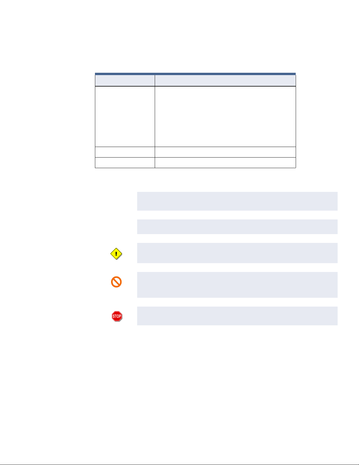
Wall Mount Enclosure
Figure 1-1 on page 1-4 shows a photograph of the iSTAR Ultra and its components in a wall
mount enclosure.
Figure 1-1: Wall Mount Enclosure
GCM
ACM 1
ACM 2
1–4 iSTAR Ultra Installation and Configuration Guide
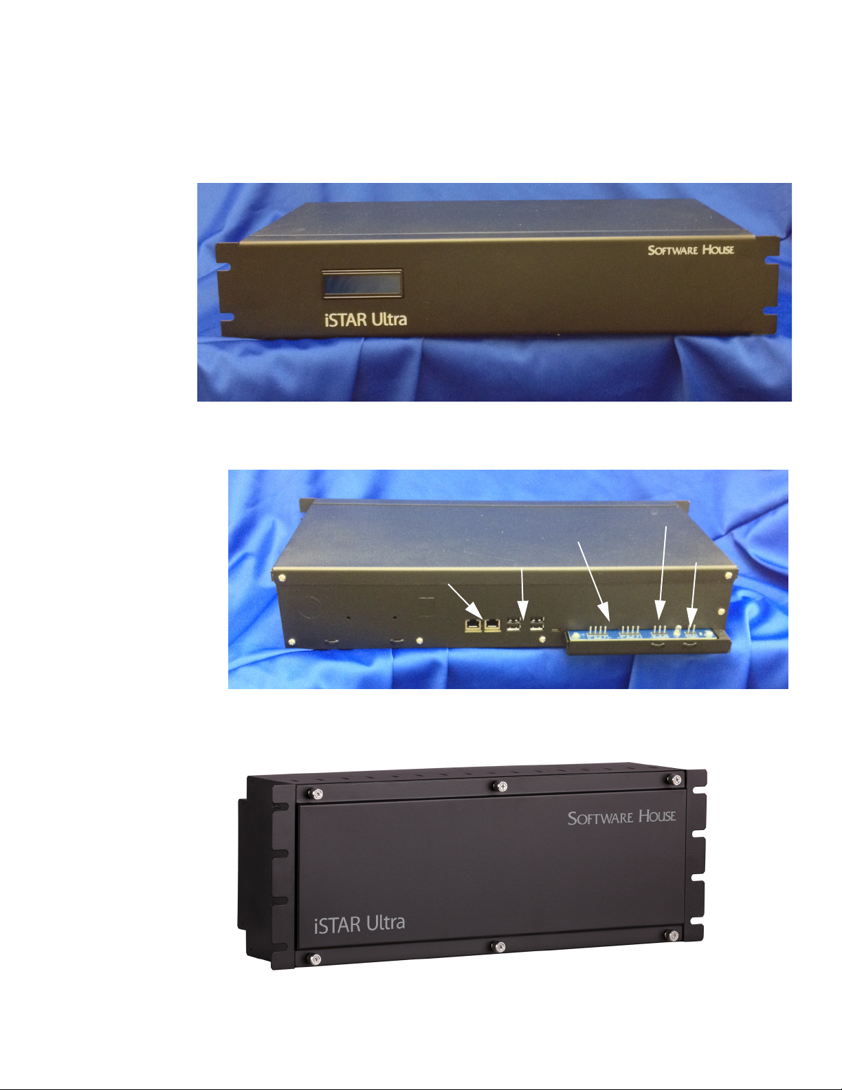
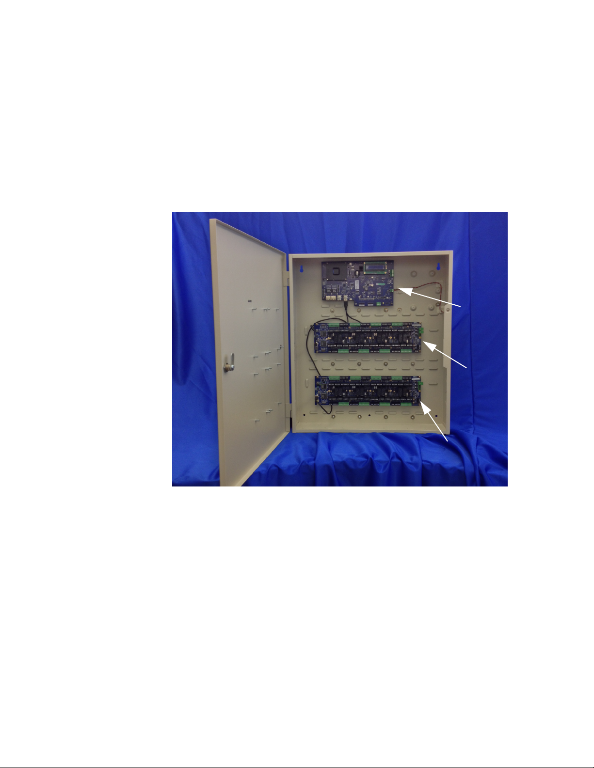
Rack Mount Enclosures
Figure 1-2 on page 1-5 shows the GCM in a rack mount enclosure.
Figure 1-3 on page 1-5 shows the rear of the GCM rack mount enclosure.
Types of Mounting
Figure 1-2: GCM Rack Mount Enclosure
LCD
LCD
Figure 1-3: GCM Rear Rack Mount Enclosure
AC Fail / Low Batt
RS-485 Ports
4 USB 2.0
2 Gbps NICs
Figure 1-4 on page 1-5 shows the ACM in rack mount enclosure.
Figure 1-4: ACM Rack Mount Enclosure
Power
iSTAR Ultra Installation and Configuration Guide 1–5
Types of Mounting
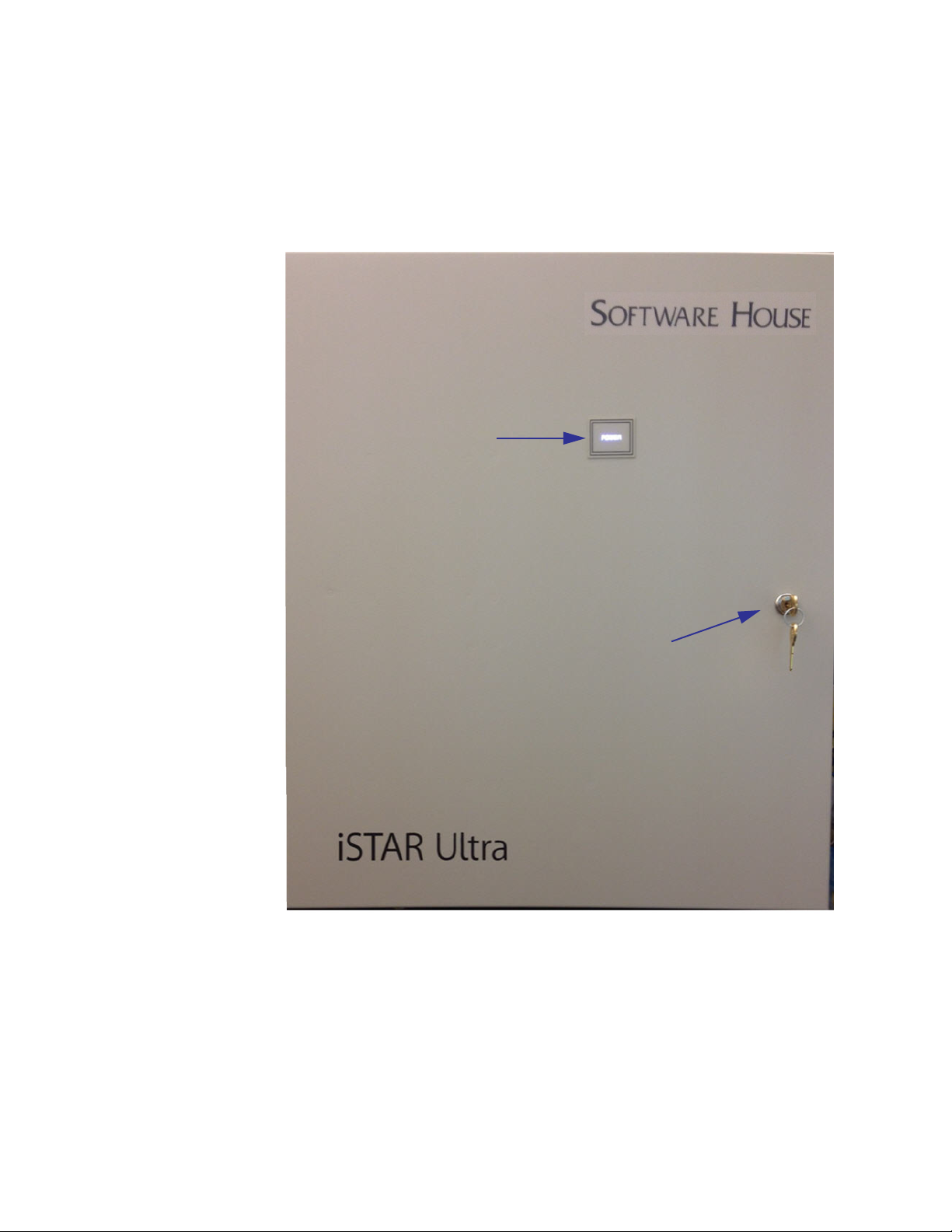
iSTAR Ultra Photograph
Figure 1-5 on page 1-6 shows a photograph of the iSTAR Ultra enclosure. The bright power
LED will shine through the Power decal when the door is closed. The bright LED will
extinguish when the door is opened.
Figure 1-5: STAR Ultra Photo
Power Indicator
Key Lock with Tamper inside
1–6 iSTAR Ultra Installation and Configuration Guide

Main Features
Processor
Storage
Power
Main Features
Freescale i.MX6 ARM processor, 1GHz
Compare iSTAR Pro @ 60 MHz, iSTAR eX @ 400 MHz
2GB DDR3 RAM
16GB SD Card
Powered by 12 Vdc, from UL Listed apS power source or other UL 603 Listed, power-
limited power supply with appropriate ratings and a minimum 4 hours of standby power.
Provides up to 1.5A @ 12Vdc unswitched to external devices:
• Wiegand signaling readers
• RS-485 ports
Provides power to relays:
• Relays configurable to be wet or dry by jumper.
• Wet Relays provide current at main input voltage (12 or 24V with external DC supply).
• Each wet relay is limited to 0.75A (at 12 or 24V).
• Each Primary dry relay is limited to 5.0A (at 12 or 24V).
• Each Secondary dry relay is limited to 1.0A (at 12 or 24V).
Full operating backup power is not provided by the board itself.
• Achieved with apS or external UPS,
• Upon loss of external power, data is written to onboard flash.
RM / Wiegand Signaling Readers (per ACM)
The ACM supports a total of 8 readers in any combination of the following:
RS-485 RM Reader (8 readers across 8 ports)
Wiegand Reader (8 readers)
There are eight basic sections, on each ACM, that support the total of eight Readers. Each
section has:
One Reader port (either)
• One RM / RS-485 Reader port*
• One Wiegand signaling port*
iSTAR Ultra Installation and Configuration Guide 1–7

Main Features
Three supervised Inputs
Two relay Outputs
One AUX output (12 Vdc)*
* The AUX power and whichever reader power is used, are limited to a total of 1.5 Amp.
Aperio Hubs and Readers (per GCM RS-485 Comm Port)
An iSTAR Ultra GCM RS-485 Port supports a total of up to:
15 Aperio Hubs
• Hubs can be 1 Port or 8 Ports
16 Aperio Wireless Readers reporting to the Hubs
In other words, there can be up to 30 Hubs and/or 32 Wireless Readers per iSTAR Ultra.
There can be any combination of Hubs and Wireless Readers that do not exceed these limits.
The configured RM / Wiegand Readers can only exist to the extent that the configured Aperio
Readers are less than 32.
I/O (per ACM)
NOTE
The maximum number of enabled readers, wired or wireless, per iSTAR
Ultra is 32.
The maximum number of readers hard wired to ACMs is 16.
24 general purpose inputs.
16 general purpose relays:
• Dry or wet contact settable per relay by jumpers.
• 4-pin connectors to support NO/NC and Dry/Wet configurations.
Special purpose inputs:
• Tamper (from enclosure door).
• Main AC fail (from apS).
• Low external battery (from apS.)
NOTE
The following 4 inputs to the host are determined by the firmware. There
is no actual wiring to the iSTAR Ultra board.
• FAI Alarm State (J40 F input).
• FAI Relay Control State.
• FAI Interlock Key State (J40 K input).
Onboard battery low.
1–8 iSTAR Ultra Installation and Configuration Guide

I/O (per GCM)
Communications
Main Features
Large standard two-piece terminal blocks and spacing minimize the potential of mis-
wiring.
1 USB 2.0 Port for communication to the GCM.
RS-485 Comm Ports
• 2 four-pin Ports for Aperio Hubs
USB 2.0 Ports
• 4 USB host port.
• The only use of USB in the first version is to connect to the ACMs and to import
encryption keys, in the same way as iSTAR eX.
• 1 USB Micro B port. (not currently used).
Serial debug port. Data is also available using ICU iWatch2.
FAI
Onboard Controls
Two 1 Gbps full duplex, Auto Sense Ethernet Ports.
FIPS-197 and AES 256-bit encryption.
Can cluster with other iSTAR Ultras either encrypted or non-encrypted.
Can cluster with iSTAR Edges, eXs, Pros, iSTAR Ultra SEs (Ultra Mode) and other iSTAR
Ultras, when encrypted.
Fire Alarm Interlock. When the F input is true, FAI activates relays that are enabled for FAI by
individual enable switches. The Primary relays (large, mounted in sockets) can be configured
to activate when the FAI signal goes true.
LCD with backlight for Status and Diagnostics.
Rotary switch for diagnostics, as with iSTAR eX and Edge.
LEDs for serial, Ethernet, power and relay states.
• Two power LEDs: one super bright LED that is on when the enclosure door is closed, and
one green LED that is always on when main power is present.
• Relay activation LEDs are not affected by enclosure door.
• All other LEDs only turn on when enclosure door is open.
Soft Reboot button. (Also backs up the DB).
Hard Reset (Stops Linux. Can be used to restore Factory defaults) See Table 5-1 on
page 5-4.
iSTAR Ultra Installation and Configuration Guide 1–9

Main Features
Housing
Switches for serial termination of RM ports.
Switches for selection of relays for control by FAI.
Switch for FAI Enable.
Switch for FAI Latch Enable.
Switch for AES Encryption.
Jumpers for relay wet/dry control.
Switch for Backup/Restore.
Rack mount Enclosures
Wall mount Enclosure
1–10 iSTAR Ultra Installation and Configuration Guide

Product Comparison
Table 1-1 compares the iSTAR Ultra with other iSTAR controllers.
Table 1-1: Product Comparison Table (i2, i3, i4, i5 are firmware suffixes)
Product Comparison
iSTAR Ultra
SE
iSTAR Ultra
Feature
Processor Freescale
Speed, MHz 1000 1000 1000 180 400 60 50
Win CE
Version
Linux yes yes yes no no no no
RAM 2 GB DDR3
Flash 16 GB SD
Cards average
card record
Cards - very
large card
record
i5
i.MX6 ARM
processor,
1GHz
N/A N/A N/A 5 5 3 3
RAM
Card
500K
(Software
limit)
500K
(Software
limit)
(Ultra Mode)
i5
Freescale
i.MX6 ARM
processor,
1GHz
2 GB DDR3
RAM
16 GB SD
Card
500K
(Software
limit)
500K
(Software
limit)
iSTAR Ultra
SE
(Pro Mode)
i5
Freescale
i.MX6 ARM
processor,
1GHz
2 GB DDR3
RAM
16 GB SD
Card
500K
(Software
limit)
500K
(Software
limit)
iSTAR Edge
i4
ARM Atmel
9260
64 MB 64 MB 64 MB 16 MB
128 MB 32 MB plus
>250K >250K >250K 27K
>100K >100K > 100K 10K
iSTAR eX
i3
ARM Marvell
PXA255
256 mb on
included CF
Card
iSTAR Pro
i2
PowerPC
Motorola
MPC860
16 MB 8 MB
PowerPC
Motorola
MPC860
iSTAR
Classic
i2
Cards - very
small card
record
Full operating
backup power
provided
External
backup power
supported
500K
(Software
limit)
No No No No Yes No No
apS, other
external UPS
or backup of
Power
Sourcing
Equipment
500K
(Software
limit)
apS, other
external UPS
or backup of
Power
Sourcing
Equipment
500K
(Software
limit)
apS, other
external UPS
or backup of
Power
Sourcing
Equipment
>400K >400K > 400K 45K
apS, other
external UPS
or backup of
Power
Sourcing
Equipment
iSTAR Ultra Installation and Configuration Guide 1–11
Other external
UPS, if wired
correctly and
our other
hardware still
used.
apS, other
external UPS
apS, other
external UPS

Product Comparison
Table 1-1: Product Comparison Table (i2, i3, i4, i5 are firmware suffixes), continued
Feature
Power fail data
backup
Onboard
Ethernet
Secondary
Ethernet
Expansion
connectors
Expansion
functions
supported
iSTAR Ultra
i5
To SD card
flash
External
Battery back
up is required
to avoid any
data loss
during a power
loss.
2 NICs each
1000, 100, 10
Auto-sense
1000, 100, 10
Auto-sense
USB, 4 Hosts,
1 Client
Encryption key
transfer
iSTAR Ultra
SE
(Ultra Mode)
i5
To SD card
flash
External
Battery back
up is required
to avoid any
data loss
during a power
loss.
2 NICs each
1000, 100, 10
Auto-sense
1000, 100, 10
Auto-sense
USB, 4 Hosts,
1 Client
Encryption key
transfer
iSTAR Ultra
SE
(Pro Mode)
iSTAR Edgei4iSTAR eX
i5
To SD card
flash
External
Battery back
up is required
to avoid any
data loss
during a power
loss.
2 NICs each
1000, 100, 10
Auto-sense
1000, 100, 10
Auto-sense
USB, 4 Hosts,
1 Client
N/A Encryption key
To onboard
flash with
on-board
Alkaline
Batteries to
provide for an
orderly shut
down and
keep the Real
Time Clock
running.
1 NIC 100, 10
Auto-sense
with optional
PoE Plus
Not supported Onboard
USB, 2 host USB, 1 host 2 PCMCIA
transfer
i3
To CF card
with SLA
Battery to
provide for an
orderly shut
down and
Coin Cell
battery to keep
the Real Time
Clock running.
2 NICs each
100, 10
Auto-sense
100, 10
Encryption key
transfer, 8reader
expansion
iSTAR Pro
i2
Sleep with
memory
retained by
onboard
batteries.
1 NIC plus
PCMCIA
option
10
Optional PC
card
slots
N/A N/A
To flash simm
1 NIC plus
PCMCIA
option
10
Optional PC
card
1 PCMCIA slot
iSTAR
Classic
i2
Dialup RRAS (future) RRAS (future) RRAS no no yes, PC card,
RRAS
Serial host
RS-232 comm
Total nonwireless
readers
allowed
Wiegand
signaling
readers
RMs allowed 8, 16 with
Total Aperio
Hubs/Readers
allowed
no no no no no yes, RRAS yes, RRAS
8, 16 with
second ACM
8, 16 with
second ACM
second ACM
30 Hubs
32 Readers
8, 16 with
second ACM
8, 16 with
second ACM
8, 16 with
second ACM
30 Hubs
32 Readers
(Future)
8, 16 with
second ACM
8, 16 with
second ACM
8, 16 with
second ACM
N/A N/A N/A N/A N/A
2 Reader - 2
4 Reader - 4
1 Reader - 1
Wiegand
2 Reader - 2
Wiegand
4 Reader - 2
Wiegand
2 Reader - 2
RM rdrs.
4 Reader - 4
RM rdrs.
4, 8 with USB
key
4 8, 16 with
4, 8 with USB
key
8, 16 with
second ACM
second ACM
8, 16 with
second ACM
yes, PC card,
RRAS
8, 16 with
second ACM
8, 16 with
second ACM
8, 16 with
second ACM
1–12 iSTAR Ultra Installation and Configuration Guide

Table 1-1: Product Comparison Table (i2, i3, i4, i5 are firmware suffixes), continued
Product Comparison
iSTAR Ultra
SE
iSTAR Ultra
Feature
I8s allowed 16 per ACM 16 per ACM 8 per ACM 2 Rdr - 4 I/8s
R8s allowed 16 per ACM 16 per ACM 8 per ACM 2 Rdr - 4 R/8s
Schlage
Wyreless
(Readers/
PIMs)
General
purpose serial
ports
Encryption Super Strong,
General
purpose Inputs
onboard
i5
32 PIMs
32 Readers
0000022
FIPS-197,
AES 256
ECC or RCA
1024
24, 48 with
second ACM
(Ultra Mode)
i5
32 PIMs
32 Readers
(Future)
Super Strong,
FIPS-197,
AES 256
ECC or RCA
1024
24, 48 with
second ACM
iSTAR Ultra
SE
(Pro Mode)
i5
16 PIMs
16 Readers
(only one
RS485 port)
No
(Cannot use
RSA RC4)
16, 32 with
second ACM
iSTAR Edge
i4
4 Rdr - 8 I/8s
4 Rdr - 8 R/8s
N/A Yes Yes N/A
Super Strong,
FIPS-197,
AES 256
ECC or RCA
1024
8 16 16, 32 with
iSTAR eX
i3
8 8, 16 with
8 8, 16 with
Super Strong,
FIPS-197,
AES 256
ECC or RCA
1024
iSTAR Pro
i2
second ACM
second ACM
RSA RC4 128
bit
second ACM
iSTAR
Classic
i2
8, 16 with
second ACM
8, 16 with
second ACM
RSA RC4 128
bit
16, 32 with
second ACM
Input resistor
configuration
Relays
onboard
Open collector
outputs
onboard
FAI Yes Yes No Yes No No No
PoE, PoE+ (future) (future) No Yes No No No
Clustering
(Encrypted)
23 choices per
INPUT,
including dual
range SWH
1K
16, 32 with
second ACM
1/2 of the
relays are
socketed.
----4--
Open collector outputs are available on RM-4s connected to the iSTAR.
1
16 Total
(Ultra, SE
Ultra Mode,
Edge, eX)
23 choices per
INPUT,
including dual
range SWH
1K
16, 32 with
second ACM
1/2 of the
relays are
socketed.
1
16 Total
(Ultra, SE
Ultra Mode,
Edge, eX)
SWH 1K dual
range or nonsupervised
8, 16 with
second ACM
All of the
relays are
socketed.
N/A
23 choices per
board,
including dual
range SWH
1K
4 4 8, 16 with
1
16 Total
(Ultra, SE
Ultra Mode,
Edge, eX)
23 choices per
board,
including dual
range SWH
1K
1
16 Total
(Ultra, SE
Ultra Mode,
Edge, eX)
SWH 1K dual
range or nonsupervised
second ACM
N/A N/A
SWH 1K dual
range or nonsupervised
8, 16 with
second ACM
iSTAR Ultra Installation and Configuration Guide 1–13

Product Comparison
Table 1-1: Product Comparison Table (i2, i3, i4, i5 are firmware suffixes), continued
iSTAR Ultra
SE
iSTAR Ultra
Feature
Clustering
(NonEncrypted)
Diagnostic
LCD
1
The iSTAR Ultra can be clustered with other encrypted iSTAR’s (Ultra, Ultra SE Ultra Mode, eX, and Edge) using AES 256. Or, clustered with
non-encrypted iSTAR’s (Ultra, Ultra SE Pro Mode, Pro, Classic).
iSTAR Ultra supports up to 32 wireless readers and up to 16 RM/Wiegand readers. The RM/Wiegand readers can only exist to the extent that
the wireless readers are less than 32.
Note: iSTAR Ultra and iSTAR Ultra SE Ultra Mode can enable or disable Encryption with S1-1.
i5
1
16 Total
(Ultra, SE
Ultra Mode,
SE Pro Mode,
Pro, Classic)
Yes Yes Yes Yes Yes Yes No
(Ultra Mode)
i5
1
16 Total
(Ultra, SE
Ultra Mode,
SE Pro Mode,
Pro, Classic)
iSTAR Ultra
SE
(Pro Mode)
i5
1
16 Total
(Ultra, SE
Ultra Mode,
SE Pro Mode,
Pro, Classic)
iSTAR Edgei4iSTAR eX
i3
N/A N/A
iSTAR Pro
i2
1
16 Total
(Ultra, SE
Ultra Mode,
SE Pro Mode,
Pro, Classic)
iSTAR
Classic
i2
1
16 Total
(Ultra, SE
Ultra Mode,
SE Pro Mode,
Pro, Classic)
1–14 iSTAR Ultra Installation and Configuration Guide

2
Site Requirements
This chapter provides information about site planning for iSTAR Ultra hardware.
In This Chapter:
Pre-Installation Planning and Requirements ............................................................................................... 2-2
Installation......................................................................................................................................................... 2-5
Power ...............................................................................................................................................................2-11
Reader Power Requirements ........................................................................................................................ 2-17
iSTAR Ultra Installation and Configuration Guide 2–1

Pre-Installation Planning and Requirements
Pre-Installation Planning and Requirements
Pre-installation involves the following:
1. Checking equipment (hardware, software, power supply, and wiring).
2. Checking power, wiring, equipment clearances, and code compliance at the site.
3. Ensuring the proper tools are available.
See the following additional requirements:
Equipment Check on page 2-2
Types of Mounting on page 2-2
Equipment Check
Verify that the contents of the shipped boxes match the packing lists. Contact Software House
if any items are missing or damaged.
The iSTAR Ultra hardware does not include mounting hardware for an installation. Mounting
hardware depends upon the site and must be approved by a structural engineer or other
certified professional.
Types of Mounting
Requirements
Software House recommends anchoring systems capable of sustaining a 75 lb. load (without
cables).
The iSTAR Ultra and its components can be installed in a wall mount enclosure or in a
separate rack mount enclosure.
Site Requirements
Ensure that the site is ready:
The iSTAR Ultra installation must be performed by a certified installer.
The iSTAR Ultra must be installed and wired according to local and national regulations.
The iSTAR Ultra must be installed in a restricted access, protected area.
Non-limited power supply lines must maintain (1/2 inch (1.3 cm)) spacing from limited
power supply lines and other signaling lines. Secure lines must be installed in accordance
to local and national electric codes.
The site must be approved and all wiring must comply with UL requirements and other
codes, in accordance with the National Electric Code, ANSI/NFPA70-1993.
All preliminary site work is complete.
System power needs to be 12 Vdc. Appropriate circuit breakers must be accessible. Power
supplies must be listed to UL-603 or UL-294.
The site is clean and free of dust or other contaminants.
2–2 iSTAR Ultra Installation and Configuration Guide
 Loading...