

Tyco iSTAR eX Installation And Configuration Manual

Installation and Configuration Guide
70 Westview Street
Lexington, MA 02421
http://www.swhouse.com
Fax: 781-466-9550 Phone: 781-466-6660
iSTAR eX
REVISION F9

C•CURE and Software House are trademarks of Tyco International Ltd. and its respective
companies.
Certain Product names mentioned herein may be trade names and/or registered trademarks
of other companies. Information about other products furnished by Software House is
believed to be accurate. However, no responsibility is assumed by Software House for the use
of these products, or for an infringement of rights of the other companies that may result from
their use.
C•CURE
®
800-8000 / C•CURE® 9000
Document Number: UM-121
Revision Number: F9
Release Date: October 2010
This manual is proprietary information of Software House. Unauthorized reproduction of any
portion of this manual is prohibited. The material in this manual is for information purposes
only. It is subject to change without notice. Software House assumes no responsibility for
incorrect information this manual may contain.
Copyright © 2009, 2010 by Tyco International Ltd. and its respective companies.
All rights reserved.

Preface
How to Use this Manual . . . . . . . . . . . . . . . . . . . . . . . . . . . . . . . . . . . . . . . . . . . . . . . . . . . . . . . xiv
Conventions . . . . . . . . . . . . . . . . . . . . . . . . . . . . . . . . . . . . . . . . . . . . . . . . . . . . . . . . . . . . . . . . . . xv
FCC Class A Digital Device Limitations . . . . . . . . . . . . . . . . . . . . . . . . . . . . . . . . . . . . . . . . . xvi
FCC Class B Notes . . . . . . . . . . . . . . . . . . . . . . . . . . . . . . . . . . . . . . . . . . . . . . . . . . . . . . . . . . . . xvii
Canadian Radio Emissions Requirements . . . . . . . . . . . . . . . . . . . . . . . . . . . . . . . . . . . . . . . . xvii
CE Compliance. . . . . . . . . . . . . . . . . . . . . . . . . . . . . . . . . . . . . . . . . . . . . . . . . . . . . . . . . . . . . . xviii
Important Safety Information . . . . . . . . . . . . . . . . . . . . . . . . . . . . . . . . . . . . . . . . . . . . . . . . . xviii
Power Supply Information . . . . . . . . . . . . . . . . . . . . . . . . . . . . . . . . . . . . . . . . . . . . . . . . . . . . . .xix
Product Information . . . . . . . . . . . . . . . . . . . . . . . . . . . . . . . . . . . . . . . . . . . . . . . . . . . . . . . . . . . xx
Chapter 1 Introducing iSTAR eX
iSTAR eX Features . . . . . . . . . . . . . . . . . . . . . . . . . . . . . . . . . . . . . . . . . . . . . . . . . . . . 1-2
Memory . . . . . . . . . . . . . . . . . . . . . . . . . . . . . . . . . . . . . . . . . . . . . . . . . . . . . . . . . . . . . . . . . 1-2
Cluster Configuration . . . . . . . . . . . . . . . . . . . . . . . . . . . . . . . . . . . . . . . . . . . . . . . . . . . . . 1-2
Events . . . . . . . . . . . . . . . . . . . . . . . . . . . . . . . . . . . . . . . . . . . . . . . . . . . . . . . . . . . . . . 1-2
System Activity . . . . . . . . . . . . . . . . . . . . . . . . . . . . . . . . . . . . . . . . . . . . . . . . . . . . . . 1-3
Antipassback Control . . . . . . . . . . . . . . . . . . . . . . . . . . . . . . . . . . . . . . . . . . . . . . . . . 1-3
Diagnostic Information . . . . . . . . . . . . . . . . . . . . . . . . . . . . . . . . . . . . . . . . . . . . . . . . . . . . 1-3
Upgrading Firmware. . . . . . . . . . . . . . . . . . . . . . . . . . . . . . . . . . . . . . . . . . . . . . . . . . . . . . 1-3
C•CURE Integration . . . . . . . . . . . . . . . . . . . . . . . . . . . . . . . . . . . . . . . . . . . . . . . . . . . . . . 1-4
Compatibility . . . . . . . . . . . . . . . . . . . . . . . . . . . . . . . . . . . . . . . . . . . . . . . . . . . . . . . . . . . . 1-4
System Components . . . . . . . . . . . . . . . . . . . . . . . . . . . . . . . . . . . . . . . . . . . . . . . . . . . . . . 1-5
iSTAR eX General Controller Module (GCM) . . . . . . . . . . . . . . . . . . . . . . . . . . . . . 1-8
GCM Features. . . . . . . . . . . . . . . . . . . . . . . . . . . . . . . . . . . . . . . . . . . . . . . . . . . . . . . . . . . . 1-8
GCM Component Layout . . . . . . . . . . . . . . . . . . . . . . . . . . . . . . . . . . . . . . . . . . . . . . . . . 1-10
iSTAR eX GCM Component Description . . . . . . . . . . . . . . . . . . . . . . . . . . . . . . . . . . . . 1-11
iSTAR eX GCM LEDs . . . . . . . . . . . . . . . . . . . . . . . . . . . . . . . . . . . . . . . . . . . . . . . . . . . . 1-12
Table of Contents
iSTAR eX Installation and Configuration Guide iii

Table of Contents
Power Management Board (PMB) . . . . . . . . . . . . . . . . . . . . . . . . . . . . . . . . . . . . . .1-13
PMB Features . . . . . . . . . . . . . . . . . . . . . . . . . . . . . . . . . . . . . . . . . . . . . . . . . . . . . . . . . . . 1-13
PMB Component Layout . . . . . . . . . . . . . . . . . . . . . . . . . . . . . . . . . . . . . . . . . . . . . . . . . 1-14
PMB Component Description . . . . . . . . . . . . . . . . . . . . . . . . . . . . . . . . . . . . . . . . . . . . . 1-15
Star Coupler Feature . . . . . . . . . . . . . . . . . . . . . . . . . . . . . . . . . . . . . . . . . . . . . . . . . . . . . 1-16
iSTAR eX GCM - PMB Interconnections . . . . . . . . . . . . . . . . . . . . . . . . . . . . . . . . . . . . 1-17
SPI (Serial Peripheral Interface) Connection . . . . . . . . . . . . . . . . . . . . . . . . . . . . . . . . . 1-18
PMB - Power Supply - Battery Interconnections. . . . . . . . . . . . . . . . . . . . . . . . . . . . . . 1-19
iSTAR eX Capacities . . . . . . . . . . . . . . . . . . . . . . . . . . . . . . . . . . . . . . . . . . . . . . . . . .1-20
GCM. . . . . . . . . . . . . . . . . . . . . . . . . . . . . . . . . . . . . . . . . . . . . . . . . . . . . . . . . . . . . . . . . . . 1-20
PMB . . . . . . . . . . . . . . . . . . . . . . . . . . . . . . . . . . . . . . . . . . . . . . . . . . . . . . . . . . . . . . . . . . . 1-20
Input/Output Capacities . . . . . . . . . . . . . . . . . . . . . . . . . . . . . . . . . . . . . . . . . . . . . . . . . 1-20
Optional Hardware Modules . . . . . . . . . . . . . . . . . . . . . . . . . . . . . . . . . . . . . . . . . . . . . . 1-22
iSTAR eX Connections . . . . . . . . . . . . . . . . . . . . . . . . . . . . . . . . . . . . . . . . . . . . . . . .1-23
Inputs. . . . . . . . . . . . . . . . . . . . . . . . . . . . . . . . . . . . . . . . . . . . . . . . . . . . . . . . . . . . . . . . . . 1-23
Outputs . . . . . . . . . . . . . . . . . . . . . . . . . . . . . . . . . . . . . . . . . . . . . . . . . . . . . . . . . . . . . . . . 1-24
Readers . . . . . . . . . . . . . . . . . . . . . . . . . . . . . . . . . . . . . . . . . . . . . . . . . . . . . . . . . . . . . . . . 1-24
iSTAR eX Tools . . . . . . . . . . . . . . . . . . . . . . . . . . . . . . . . . . . . . . . . . . . . . . . . . . . . . .1-25
ICU . . . . . . . . . . . . . . . . . . . . . . . . . . . . . . . . . . . . . . . . . . . . . . . . . . . . . . . . . . . . . . . . . . . . 1-25
Configuring Controllers . . . . . . . . . . . . . . . . . . . . . . . . . . . . . . . . . . . . . . . . . . . . . . 1-26
Viewing Controller Status . . . . . . . . . . . . . . . . . . . . . . . . . . . . . . . . . . . . . . . . . . . . 1-26
iSTAR Web-Based Diagnostic Utility . . . . . . . . . . . . . . . . . . . . . . . . . . . . . . . . . . . . . . . 1-26
Power System . . . . . . . . . . . . . . . . . . . . . . . . . . . . . . . . . . . . . . . . . . . . . . . . . . . . . . . . . . . 1-27
Power Supply . . . . . . . . . . . . . . . . . . . . . . . . . . . . . . . . . . . . . . . . . . . . . . . . . . . . . . . 1-28
Power Supply/Battery Switch-over Circuitry. . . . . . . . . . . . . . . . . . . . . . . . . . . . 1-28
Battery Charger Circuitry . . . . . . . . . . . . . . . . . . . . . . . . . . . . . . . . . . . . . . . . . . . . . 1-28
Alarms, LEDs, and Battery (Standard Model with Power Supply and Battery) . . . 1-28
Power Failure Alarm . . . . . . . . . . . . . . . . . . . . . . . . . . . . . . . . . . . . . . . . . . . . . . . . . 1-28
Battery Low Alarm . . . . . . . . . . . . . . . . . . . . . . . . . . . . . . . . . . . . . . . . . . . . . . . . . . 1-28
Power-On LED Indicator . . . . . . . . . . . . . . . . . . . . . . . . . . . . . . . . . . . . . . . . . . . . . 1-29
Battery Charging LED . . . . . . . . . . . . . . . . . . . . . . . . . . . . . . . . . . . . . . . . . . . . . . . . 1-29
Heartbeat LED . . . . . . . . . . . . . . . . . . . . . . . . . . . . . . . . . . . . . . . . . . . . . . . . . . . . . . 1-29
Standby Battery . . . . . . . . . . . . . . . . . . . . . . . . . . . . . . . . . . . . . . . . . . . . . . . . . . . . . 1-29
Battery Operating and Charging Time . . . . . . . . . . . . . . . . . . . . . . . . . . . . . . . . . . 1-29
Alarms, LEDs, and Battery (Model NPS) . . . . . . . . . . . . . . . . . . . . . . . . . . . . . . . . . . . . 1-29
Power Failure Alarm . . . . . . . . . . . . . . . . . . . . . . . . . . . . . . . . . . . . . . . . . . . . . . . . . 1-30
Battery Low Alarm . . . . . . . . . . . . . . . . . . . . . . . . . . . . . . . . . . . . . . . . . . . . . . . . . . 1-30
iv iSTAR eX Installation and Configuration Guide

Power-On LED Indicator . . . . . . . . . . . . . . . . . . . . . . . . . . . . . . . . . . . . . . . . . . . . . 1-30
Heartbeat LED . . . . . . . . . . . . . . . . . . . . . . . . . . . . . . . . . . . . . . . . . . . . . . . . . . . . . . 1-30
Backup and Restore . . . . . . . . . . . . . . . . . . . . . . . . . . . . . . . . . . . . . . . . . . . . . . . . . . 1-31
State and Configuration Backups . . . . . . . . . . . . . . . . . . . . . . . . . . . . . . . . . . . . . . . . . . 1-31
Event Triggered Backup . . . . . . . . . . . . . . . . . . . . . . . . . . . . . . . . . . . . . . . . . . . . . . 1-32
iSTAR eX Backup and Real Time Clock . . . . . . . . . . . . . . . . . . . . . . . . . . . . . . . . . 1-32
iSTAR eX Power Failure Signals . . . . . . . . . . . . . . . . . . . . . . . . . . . . . . . . . . . . . . . . . . . 1-32
Standard Model with Power Supply and Battery. . . . . . . . . . . . . . . . . . . . . . . . . 1-32
iSTAR eX Power Failure Signals . . . . . . . . . . . . . . . . . . . . . . . . . . . . . . . . . . . . . . . . . . . 1-33
Model NPS . . . . . . . . . . . . . . . . . . . . . . . . . . . . . . . . . . . . . . . . . . . . . . . . . . . . . . . . . 1-33
PMB . . . . . . . . . . . . . . . . . . . . . . . . . . . . . . . . . . . . . . . . . . . . . . . . . . . . . . . . . . . . . . . 1-34
iSTAR eX Power Fail Detection and Backup Logic. . . . . . . . . . . . . . . . . . . . . . . . . . . . 1-36
AC Fail. . . . . . . . . . . . . . . . . . . . . . . . . . . . . . . . . . . . . . . . . . . . . . . . . . . . . . . . . . . . . 1-36
Low Battery. . . . . . . . . . . . . . . . . . . . . . . . . . . . . . . . . . . . . . . . . . . . . . . . . . . . . . . . . 1-36
Backup Now (Standard Version only) . . . . . . . . . . . . . . . . . . . . . . . . . . . . . . . . . . 1-36
Backup Restore Process. . . . . . . . . . . . . . . . . . . . . . . . . . . . . . . . . . . . . . . . . . . . . . . . . . . 1-37
Preventing Restarts without Power . . . . . . . . . . . . . . . . . . . . . . . . . . . . . . . . . . . . 1-37
Restore . . . . . . . . . . . . . . . . . . . . . . . . . . . . . . . . . . . . . . . . . . . . . . . . . . . . . . . . . . . . . 1-37
Chapter 2 iSTAR eX Topology
iSTAR eX Network Topology. . . . . . . . . . . . . . . . . . . . . . . . . . . . . . . . . . . . . . . . . . . 2-2
Lan and Wan Configurations. . . . . . . . . . . . . . . . . . . . . . . . . . . . . . . . . . . . . . . . . . . . . . . 2-2
Gateways and Firewalls . . . . . . . . . . . . . . . . . . . . . . . . . . . . . . . . . . . . . . . . . . . . . . . . . . . 2-2
Local Address Management. . . . . . . . . . . . . . . . . . . . . . . . . . . . . . . . . . . . . . . . . . . . 2-3
IP Management Tools . . . . . . . . . . . . . . . . . . . . . . . . . . . . . . . . . . . . . . . . . . . . . . . . . . . . . 2-4
Using NetBIOS and Fully Qualified Domain Names. . . . . . . . . . . . . . . . . . . . . . . . . . . 2-5
Cluster Configuration . . . . . . . . . . . . . . . . . . . . . . . . . . . . . . . . . . . . . . . . . . . . . . . . . 2-6
Master and Member Configuration . . . . . . . . . . . . . . . . . . . . . . . . . . . . . . . . . . . . . . . . . 2-6
Single Master and Alternate Master Configurations . . . . . . . . . . . . . . . . . . . . . . . 2-7
Single Master Configurations . . . . . . . . . . . . . . . . . . . . . . . . . . . . . . . . . . . . . . . . . . . . . . 2-8
Alternate Master Configurations. . . . . . . . . . . . . . . . . . . . . . . . . . . . . . . . . . . . . . . . . . . . 2-8
Primary Communications Path . . . . . . . . . . . . . . . . . . . . . . . . . . . . . . . . . . . . . . . . . . . . . 2-9
Secondary Communications Path . . . . . . . . . . . . . . . . . . . . . . . . . . . . . . . . . . . . . . . . . . 2-10
Maintaining Cluster Communication . . . . . . . . . . . . . . . . . . . . . . . . . . . . . . . . . . . 2-11
Single Master Configurations . . . . . . . . . . . . . . . . . . . . . . . . . . . . . . . . . . . . . . . . . . . . . 2-11
Alternate Master Configuration . . . . . . . . . . . . . . . . . . . . . . . . . . . . . . . . . . . . . . . . . . . 2-12
iSTAR eX Installation and Configuration Guide v

Table of Contents
Communication Between Members and Master. . . . . . . . . . . . . . . . . . . . . . . . . . . . . . 2-13
Adding Controllers to the Cluster . . . . . . . . . . . . . . . . . . . . . . . . . . . . . . . . . . . . . .2-14
Configuring Communication Paths . . . . . . . . . . . . . . . . . . . . . . . . . . . . . . . . . . . . .2-15
Planning Primary Communications . . . . . . . . . . . . . . . . . . . . . . . . . . . . . . . . . . . . . . . . 2-15
Primary Communication Guidelines . . . . . . . . . . . . . . . . . . . . . . . . . . . . . . . . . . . 2-15
Planning Secondary Communications . . . . . . . . . . . . . . . . . . . . . . . . . . . . . . . . . . . . . . 2-16
Chapter 3 Site Requirements
Pre-Installation Planning . . . . . . . . . . . . . . . . . . . . . . . . . . . . . . . . . . . . . . . . . . . . . . .3-2
Equipment Check. . . . . . . . . . . . . . . . . . . . . . . . . . . . . . . . . . . . . . . . . . . . . . . . . . . . . . . . . 3-2
Site Check . . . . . . . . . . . . . . . . . . . . . . . . . . . . . . . . . . . . . . . . . . . . . . . . . . . . . . . . . . . . . . . 3-2
Voltage Requirements and Distance . . . . . . . . . . . . . . . . . . . . . . . . . . . . . . . . . . . . . . . . . 3-3
Installation Tools . . . . . . . . . . . . . . . . . . . . . . . . . . . . . . . . . . . . . . . . . . . . . . . . . . . . . . . . . 3-3
Installation Requirements . . . . . . . . . . . . . . . . . . . . . . . . . . . . . . . . . . . . . . . . . . . . . .3-4
Host System Requirements . . . . . . . . . . . . . . . . . . . . . . . . . . . . . . . . . . . . . . . . . . . . . . . . 3-4
iSTAR eX Cabinet Requirements . . . . . . . . . . . . . . . . . . . . . . . . . . . . . . . . . . . . . . . . . . . . 3-4
Environmental Requirements . . . . . . . . . . . . . . . . . . . . . . . . . . . . . . . . . . . . . . . . . . . . . . 3-4
Power Requirements (Standard Power Supply and NPS Models) . . . . . . . . . . . . . . . 3-5
iSTAR eX Components and Boards . . . . . . . . . . . . . . . . . . . . . . . . . . . . . . . . . . . . . 3-5
iSTAR eX Input Power Rating . . . . . . . . . . . . . . . . . . . . . . . . . . . . . . . . . . . . . . . . . . 3-6
Individual/Total Loads evaluated by UL . . . . . . . . . . . . . . . . . . . . . . . . . . . . . . . . . . . . 3-6
iSTAR eX GCM Wiegand Reader Ports . . . . . . . . . . . . . . . . . . . . . . . . . . . . . . . . . . 3-7
Software House Readers. . . . . . . . . . . . . . . . . . . . . . . . . . . . . . . . . . . . . . . . . . . . . . . 3-8
Third Party Readers. . . . . . . . . . . . . . . . . . . . . . . . . . . . . . . . . . . . . . . . . . . . . . . . . . . 3-9
Wyreless Products . . . . . . . . . . . . . . . . . . . . . . . . . . . . . . . . . . . . . . . . . . . . . . . . . . . . 3-9
Ethernet Requirements . . . . . . . . . . . . . . . . . . . . . . . . . . . . . . . . . . . . . . . . . . . . . . . . . . . 3-10
Wiring Requirements . . . . . . . . . . . . . . . . . . . . . . . . . . . . . . . . . . . . . . . . . . . . . . . . . . . . 3-10
Grounding Requirements . . . . . . . . . . . . . . . . . . . . . . . . . . . . . . . . . . . . . . . . . . . . . . . . . 3-12
Chapter 4 Hardware Installation
Installation Overview . . . . . . . . . . . . . . . . . . . . . . . . . . . . . . . . . . . . . . . . . . . . . . . . . .4-2
Installation Procedure . . . . . . . . . . . . . . . . . . . . . . . . . . . . . . . . . . . . . . . . . . . . . . . . . . . . . 4-2
Mounting the Enclosure . . . . . . . . . . . . . . . . . . . . . . . . . . . . . . . . . . . . . . . . . . . . . . . .4-3
Static Electricity . . . . . . . . . . . . . . . . . . . . . . . . . . . . . . . . . . . . . . . . . . . . . . . . . . . . . . . . . . 4-3
Connecting to the Host . . . . . . . . . . . . . . . . . . . . . . . . . . . . . . . . . . . . . . . . . . . . . . . . .4-7
vi iSTAR eX Installation and Configuration Guide

Primary and Secondary Connections . . . . . . . . . . . . . . . . . . . . . . . . . . . . . . . . . . . . . . . . 4-7
Connecting to the Host via the Network . . . . . . . . . . . . . . . . . . . . . . . . . . . . . . . . . . . . . 4-7
To connect to a 10/100Base-T network. . . . . . . . . . . . . . . . . . . . . . . . . . . . . . . . . . . 4-7
Low Battery, AC Power Fail, and Tamper Inputs. . . . . . . . . . . . . . . . . . . . . . . . . . . . . . 4-9
Tamper. . . . . . . . . . . . . . . . . . . . . . . . . . . . . . . . . . . . . . . . . . . . . . . . . . . . . . . . . . . . . . 4-9
Low Battery and AC Power Fail (Standard Power Supply Model) . . . . . . . . . . . 4-9
Low Battery and AC Power Fail (NPS Model) . . . . . . . . . . . . . . . . . . . . . . . . . . . . 4-9
Connecting AC Power to UL Recognized ESD Power Supply . . . . . . . . . . . . . . 4-12
ESD Power Supply. . . . . . . . . . . . . . . . . . . . . . . . . . . . . . . . . . . . . . . . . . . . . . . . . . . . . . . 4-12
Grounding Procedure . . . . . . . . . . . . . . . . . . . . . . . . . . . . . . . . . . . . . . . . . . . . . . . . . . . . 4-13
iSTAR eX Power Supply Layout - Standard and NPS Versions. . . . . . . . . . . . . . . . . 4-13
Standard Version Power Supply Layout . . . . . . . . . . . . . . . . . . . . . . . . . . . . . . . . 4-13
NPS Version Layout (External Power Supply) . . . . . . . . . . . . . . . . . . . . . . . . . . . 4-13
iSTAR eX UL System Configuration . . . . . . . . . . . . . . . . . . . . . . . . . . . . . . . . . . . . . . . . 4-16
Standard or NPS Version (External Power) . . . . . . . . . . . . . . . . . . . . . . . . . . . . . . 4-16
iSTAR eX Connections. . . . . . . . . . . . . . . . . . . . . . . . . . . . . . . . . . . . . . . . . . . . . . . . 4-17
Wiring RM and Wyreless Readers, I/8s and R/8s to PMB. . . . . . . . . . . . . . . . . . . . . 4-18
PMB Connections. . . . . . . . . . . . . . . . . . . . . . . . . . . . . . . . . . . . . . . . . . . . . . . . . . . . . . . . 4-19
Wiring RM Devices to PMB . . . . . . . . . . . . . . . . . . . . . . . . . . . . . . . . . . . . . . . . . . . . . . . 4-21
Wiring Wyreless PIMs to the PMB . . . . . . . . . . . . . . . . . . . . . . . . . . . . . . . . . . . . . . . . . 4-21
iSTAR eX PMB - Wyreless Pinouts . . . . . . . . . . . . . . . . . . . . . . . . . . . . . . . . . . . . . . . . . 4-22
Wiring Inputs and Outputs to the GCM. . . . . . . . . . . . . . . . . . . . . . . . . . . . . . . . . 4-23
Wiring Inputs to the iSTAR eX GCM . . . . . . . . . . . . . . . . . . . . . . . . . . . . . . . . . . . . . . . 4-23
Wiring NC and NO Double Inputs . . . . . . . . . . . . . . . . . . . . . . . . . . . . . . . . . . . . . 4-24
Wiring NC and NO Single Inputs . . . . . . . . . . . . . . . . . . . . . . . . . . . . . . . . . . . . . . 4-24
Wiring Non-Supervised Inputs . . . . . . . . . . . . . . . . . . . . . . . . . . . . . . . . . . . . . . . . 4-25
Wiring Double Inputs Using Common . . . . . . . . . . . . . . . . . . . . . . . . . . . . . . . . . 4-25
Wiring Relay Outputs to iSTAR eX GCM . . . . . . . . . . . . . . . . . . . . . . . . . . . . . . . . . . . 4-26
Wiring Open Collectors to iSTAR eX GCM . . . . . . . . . . . . . . . . . . . . . . . . . . . . . . . . . . 4-27
Wiring Collector Outputs using Internal Supply . . . . . . . . . . . . . . . . . . . . . . . . . 4-27
Wiring Collector Outputs using External Supply. . . . . . . . . . . . . . . . . . . . . . . . . 4-28
Wiring Wiegand Readers to iSTAR eX GCM . . . . . . . . . . . . . . . . . . . . . . . . . . . . . . . . 4-28
Wiring Direct Wiegand Readers . . . . . . . . . . . . . . . . . . . . . . . . . . . . . . . . . . . . . . . 4-28
LED Connections . . . . . . . . . . . . . . . . . . . . . . . . . . . . . . . . . . . . . . . . . . . . . . . . . . . . 4-29
LED Control . . . . . . . . . . . . . . . . . . . . . . . . . . . . . . . . . . . . . . . . . . . . . . . . . . . . . . . . . . . . 4-29
External Bi-color LED Control . . . . . . . . . . . . . . . . . . . . . . . . . . . . . . . . . . . . . . . . . . . . . 4-30
iSTAR eX Installation and Configuration Guide vii

Table of Contents
2 Wire (Red and Green) . . . . . . . . . . . . . . . . . . . . . . . . . . . . . . . . . . . . . . . . . . . . . . 4-30
1 Wire (Yellow). . . . . . . . . . . . . . . . . . . . . . . . . . . . . . . . . . . . . . . . . . . . . . . . . . . . . . 4-31
3 Wire (Red, Green, Yellow). . . . . . . . . . . . . . . . . . . . . . . . . . . . . . . . . . . . . . . . . . . 4-32
One Wire ABC LED Control . . . . . . . . . . . . . . . . . . . . . . . . . . . . . . . . . . . . . . . . . . . . . . 4-33
One Wire (A, B, C) . . . . . . . . . . . . . . . . . . . . . . . . . . . . . . . . . . . . . . . . . . . . . . . . . . . 4-33
NPS Version (External Power Supply) . . . . . . . . . . . . . . . . . . . . . . . . . . . . . . . . . . . . . . 4-34
iSTAR eX - Support for iSTAR eX 8 Reader Option. . . . . . . . . . . . . . . . . . . . . . . .4-36
Normal iSTAR eX Operation - Supports 4 Readers . . . . . . . . . . . . . . . . . . . . . . . 4-36
Optional iSTAR eX Configuration - Supports 8 Readers . . . . . . . . . . . . . . . . . . . 4-36
Configuring an iSTAR eX Controller for 8 Readers . . . . . . . . . . . . . . . . . . . . . . . . . . . 4-38
Using the USB Security Key to Enable Readers 5-8 . . . . . . . . . . . . . . . . . . . . . . . 4-39
Monitoring Station. . . . . . . . . . . . . . . . . . . . . . . . . . . . . . . . . . . . . . . . . . . . . . . . . . . 4-42
Journal Reports. . . . . . . . . . . . . . . . . . . . . . . . . . . . . . . . . . . . . . . . . . . . . . . . . . . . . . 4-44
ICU Configuration Screen Status. . . . . . . . . . . . . . . . . . . . . . . . . . . . . . . . . . . . . . . 4-45
iSTAR Web Page Diagnostic Utility . . . . . . . . . . . . . . . . . . . . . . . . . . . . . . . . . . . . 4-47
Exporting Custom Certificates with the 8 Reader Option . . . . . . . . . . . . . . . . . . 4-48
Chapter 5 Using the iSTAR Configuration Utility (ICU)
Overview . . . . . . . . . . . . . . . . . . . . . . . . . . . . . . . . . . . . . . . . . . . . . . . . . . . . . . . . . . . .5-2
Configuring a Master Controller . . . . . . . . . . . . . . . . . . . . . . . . . . . . . . . . . . . . . . . . . . . . 5-3
Troubleshooting Tools . . . . . . . . . . . . . . . . . . . . . . . . . . . . . . . . . . . . . . . . . . . . . . . . . . . . 5-3
C•CURE 800/8000 Configuration Diagnostics. . . . . . . . . . . . . . . . . . . . . . . . . . . . . . . . 5-3
General Configuration Procedure. . . . . . . . . . . . . . . . . . . . . . . . . . . . . . . . . . . . . . . .5-4
LAN Configurations . . . . . . . . . . . . . . . . . . . . . . . . . . . . . . . . . . . . . . . . . . . . . . . . . . . . . . 5-4
WAN Configurations . . . . . . . . . . . . . . . . . . . . . . . . . . . . . . . . . . . . . . . . . . . . . . . . . . . . . 5-5
Copying the ICU onto a PC or Laptop. . . . . . . . . . . . . . . . . . . . . . . . . . . . . . . . . . . .5-8
Understanding the ICU . . . . . . . . . . . . . . . . . . . . . . . . . . . . . . . . . . . . . . . . . . . . . . . .5-9
Displaying and Updating Cluster Information . . . . . . . . . . . . . . . . . . . . . . . . . . . . . . . . 5-9
ICU Block Feature . . . . . . . . . . . . . . . . . . . . . . . . . . . . . . . . . . . . . . . . . . . . . . . . . . . .5-10
Starting the ICU . . . . . . . . . . . . . . . . . . . . . . . . . . . . . . . . . . . . . . . . . . . . . . . . . . . . . .5-11
Refreshing Controller Information . . . . . . . . . . . . . . . . . . . . . . . . . . . . . . . . . . . . . .5-13
Setting ICU Options . . . . . . . . . . . . . . . . . . . . . . . . . . . . . . . . . . . . . . . . . . . . . . . . . .5-13
Setting a Refresh Interval . . . . . . . . . . . . . . . . . . . . . . . . . . . . . . . . . . . . . . . . . . . . . . . . . 5-14
Changing the ICU Password . . . . . . . . . . . . . . . . . . . . . . . . . . . . . . . . . . . . . . . . . . . . . . 5-15
viii iSTAR eX Installation and Configuration Guide

Setting the Public IP Address for Firmware Downloads. . . . . . . . . . . . . . . . . . . . . . . 5-15
Setting the TCP/IP Port for Firmware Downloads . . . . . . . . . . . . . . . . . . . . . . . . . . . 5-15
Using the ICU Window . . . . . . . . . . . . . . . . . . . . . . . . . . . . . . . . . . . . . . . . . . . . . . . 5-16
The Toolbar. . . . . . . . . . . . . . . . . . . . . . . . . . . . . . . . . . . . . . . . . . . . . . . . . . . . . . . . . . . . . 5-16
Icons . . . . . . . . . . . . . . . . . . . . . . . . . . . . . . . . . . . . . . . . . . . . . . . . . . . . . . . . . . . . . . . . . . . 5-17
Display Area . . . . . . . . . . . . . . . . . . . . . . . . . . . . . . . . . . . . . . . . . . . . . . . . . . . . . . . . . . . . 5-19
Menu Bar. . . . . . . . . . . . . . . . . . . . . . . . . . . . . . . . . . . . . . . . . . . . . . . . . . . . . . . . . . . . . . . 5-21
Status Bar. . . . . . . . . . . . . . . . . . . . . . . . . . . . . . . . . . . . . . . . . . . . . . . . . . . . . . . . . . . . . . . 5-21
Configuring a Controller. . . . . . . . . . . . . . . . . . . . . . . . . . . . . . . . . . . . . . . . . . . . . . 5-22
Prerequisite Information. . . . . . . . . . . . . . . . . . . . . . . . . . . . . . . . . . . . . . . . . . . . . . . . . . 5-22
Configuring SNMP . . . . . . . . . . . . . . . . . . . . . . . . . . . . . . . . . . . . . . . . . . . . . . . . . . 5-29
Digital Certificate Signing and Restore Options . . . . . . . . . . . . . . . . . . . . . . . . . . 5-33
Connecting to the iSTAR Web Page Diagnostic Utility . . . . . . . . . . . . . . . . . . . . 5-35
Disabling Web Diagnostics. . . . . . . . . . . . . . . . . . . . . . . . . . . . . . . . . . . . . . . . . . . . . . . . 5-38
Sending Messages to Other ICU Users . . . . . . . . . . . . . . . . . . . . . . . . . . . . . . . . . . 5-39
Downloading Firmware Updates . . . . . . . . . . . . . . . . . . . . . . . . . . . . . . . . . . . . . . 5-40
Chapter 6 iSTAR Web Page Diagnostic Utility
Starting the Diagnostic Utility . . . . . . . . . . . . . . . . . . . . . . . . . . . . . . . . . . . . . . . . . . 6-2
Navigating the Diagnostic Utility . . . . . . . . . . . . . . . . . . . . . . . . . . . . . . . . . . . . . . . 6-3
Viewing the Status Screen. . . . . . . . . . . . . . . . . . . . . . . . . . . . . . . . . . . . . . . . . . . . . . 6-4
Viewing the Cluster Information Screen . . . . . . . . . . . . . . . . . . . . . . . . . . . . . . . . . 6-7
Viewing the Object Store Database Screen. . . . . . . . . . . . . . . . . . . . . . . . . . . . . . . . 6-8
Diagnostic Screens . . . . . . . . . . . . . . . . . . . . . . . . . . . . . . . . . . . . . . . . . . . . . . . . . . . 6-10
Network Diagnostics . . . . . . . . . . . . . . . . . . . . . . . . . . . . . . . . . . . . . . . . . . . . . . . . . . . . . 6-10
Reader and I/O Diagnostics. . . . . . . . . . . . . . . . . . . . . . . . . . . . . . . . . . . . . . . . . . . . . . . 6-11
SID Diagnostic Levels . . . . . . . . . . . . . . . . . . . . . . . . . . . . . . . . . . . . . . . . . . . . . . . . . . . . 6-12
Displaying Diagnostic Information. . . . . . . . . . . . . . . . . . . . . . . . . . . . . . . . . . . . . 6-12
Chapter 7 Using the LCD Diagnostic Display
Setting the LCD Message Display . . . . . . . . . . . . . . . . . . . . . . . . . . . . . . . . . . . . . . . 7-2
Displaying Status Messages . . . . . . . . . . . . . . . . . . . . . . . . . . . . . . . . . . . . . . . . . . . . 7-3
iSTAR eX Installation and Configuration Guide ix

Table of Contents
Setting LCD Status Message Display . . . . . . . . . . . . . . . . . . . . . . . . . . . . . . . . . . . . . . . . 7-3
iSTAR eX Diagnostic Tests. . . . . . . . . . . . . . . . . . . . . . . . . . . . . . . . . . . . . . . . . . . . . .7-4
Card Reader Diagnostics . . . . . . . . . . . . . . . . . . . . . . . . . . . . . . . . . . . . . . . . . . . . . . . . . . 7-4
Output Diagnostics . . . . . . . . . . . . . . . . . . . . . . . . . . . . . . . . . . . . . . . . . . . . . . . . . . . . . . . 7-5
Output Change Display (Slow Mode) . . . . . . . . . . . . . . . . . . . . . . . . . . . . . . . . . . . 7-5
Output Change Display (Fast Mode) . . . . . . . . . . . . . . . . . . . . . . . . . . . . . . . . . . . . 7-5
Output Test Mode . . . . . . . . . . . . . . . . . . . . . . . . . . . . . . . . . . . . . . . . . . . . . . . . . . . . 7-6
Input Change Display Mode . . . . . . . . . . . . . . . . . . . . . . . . . . . . . . . . . . . . . . . . . . . . . . . 7-6
Port and CF Slot Test . . . . . . . . . . . . . . . . . . . . . . . . . . . . . . . . . . . . . . . . . . . . . . . . . . . . . . 7-7
STAR eX Diagnostic Tests . . . . . . . . . . . . . . . . . . . . . . . . . . . . . . . . . . . . . . . . . . . . . .7-8
Appendix A Controls and Indicators
iSTAR eX GCM Controls and Indicators . . . . . . . . . . . . . . . . . . . . . . . . . . . . . . . . . A-2
iSTAR eX GCM LEDs . . . . . . . . . . . . . . . . . . . . . . . . . . . . . . . . . . . . . . . . . . . . . . . . . . . . . A-3
Diagnostic and Status Messages . . . . . . . . . . . . . . . . . . . . . . . . . . . . . . . . . . . . . . . . A-4
PMB Controls and Indicators. . . . . . . . . . . . . . . . . . . . . . . . . . . . . . . . . . . . . . . . . . . A-5
LED Control . . . . . . . . . . . . . . . . . . . . . . . . . . . . . . . . . . . . . . . . . . . . . . . . . . . . . . . . . . . . . A-6
External Bi-color LED Control . . . . . . . . . . . . . . . . . . . . . . . . . . . . . . . . . . . . . . . . . . . . . . A-6
2 Wire (Red and Green) . . . . . . . . . . . . . . . . . . . . . . . . . . . . . . . . . . . . . . . . . . . . . . . A-7
1 Wire (Yellow). . . . . . . . . . . . . . . . . . . . . . . . . . . . . . . . . . . . . . . . . . . . . . . . . . . . . . . A-8
3 Wire (Red, Green, Yellow). . . . . . . . . . . . . . . . . . . . . . . . . . . . . . . . . . . . . . . . . . . . A-9
One Wire (A, B, C) . . . . . . . . . . . . . . . . . . . . . . . . . . . . . . . . . . . . . . . . . . . . . . . . . . . A-10
iSTAR eX PMB - Wyreless Pinouts . . . . . . . . . . . . . . . . . . . . . . . . . . . . . . . . . . . . . . . . . A-11
Appendix B Part Numbers
iSTAR eX Part Numbers. . . . . . . . . . . . . . . . . . . . . . . . . . . . . . . . . . . . . . . . . . . . . . . B-2
Appendix C Maintenance
Maintenance and Diagnostic Schedule . . . . . . . . . . . . . . . . . . . . . . . . . . . . . . . . . . C-2
Lead Acid Battery Replacement / Maintenance - Yearly . . . . . . . . . . . . . . . . . . . . . . . C-2
Lithium Battery Replacement - As Needed . . . . . . . . . . . . . . . . . . . . . . . . . . . . . . . . . . . C-2
Fuse Replacement - As Needed . . . . . . . . . . . . . . . . . . . . . . . . . . . . . . . . . . . . . . . . . . . . . C-2
Diagnostic Tests - As needed . . . . . . . . . . . . . . . . . . . . . . . . . . . . . . . . . . . . . . . . . . . . . . . C-2
x iSTAR eX Installation and Configuration Guide

Appendix D iSTAR eX Wire Routing Diagrams
iSTAR eX Wire Routing Diagrams. . . . . . . . . . . . . . . . . . . . . . . . . . . . . . . . . . . . . . .D-2
Index
iSTAR eX Installation and Configuration Guide xi

Table of Contents
xii iSTAR eX Installation and Configuration Guide

Preface
The iSTAR eX Installation and Configuration Guide is for experienced security
system installers responsible for installing iSTAR eX controllers on a network.
In This Preface
How to Use this Manual . . . . . . . . . . . . . . . . . . . . . . . . . . . . . . . . . . . . . . . . . . . . . . . . xiv
Conventions . . . . . . . . . . . . . . . . . . . . . . . . . . . . . . . . . . . . . . . . . . . . . . . . . . . . . . . . . . . . xv
FCC Class A Digital Device Limitations . . . . . . . . . . . . . . . . . . . . . . . . . . . . . . . . . . . xvi
FCC Class B Notes . . . . . . . . . . . . . . . . . . . . . . . . . . . . . . . . . . . . . . . . . . . . . . . . . . . . . xvii
Canadian Radio Emissions Requirements . . . . . . . . . . . . . . . . . . . . . . . . . . . . . . . . . xvii
CE Compliance . . . . . . . . . . . . . . . . . . . . . . . . . . . . . . . . . . . . . . . . . . . . . . . . . . . . . . . xviii
Important Safety Information . . . . . . . . . . . . . . . . . . . . . . . . . . . . . . . . . . . . . . . . . . . xviii
Power Supply Information . . . . . . . . . . . . . . . . . . . . . . . . . . . . . . . . . . . . . . . . . . . . . . .xix
Product Information . . . . . . . . . . . . . . . . . . . . . . . . . . . . . . . . . . . . . . . . . . . . . . . . . . . 0-xx
iSTAR eX Installation and Configuration Guide xiii

Preface
How to Use this Manual
This manual contains the following information:
Table 1: Manual Contents
Chapter/Appendix Title Description
Chapter 1 Introducing iSTAR eX Provides basic information about iSTAR eX, and includes
an overview of iSTAR eX hardware, features, and
configuration tools.
Chapter 2 iSTAR eX Topology Provides the information that you need to set up
iSTAR eX controllers for network communications.
Chapter 3 Site Requirements Provides physical requirements for iSTAR eX
configuration.
Chapter 4 Hardware Installation Gives an overview of the iSTAR eX hardware installation
and provides step-by-step installation procedures.
Chapter 5 Using the iSTAR
Configuration Utility (ICU)
Chapter 6 iSTAR eX Web Page
Diagnostic Utility
Chapter 7 iSTAR eX LCD Diagnostic
Utility
Appendix A iSTAR eX Controls and
Indicators
Appendix B Part Numbers Contains part numbers for iSTAR eX components.
Appendix C Maintenance and Diagnostics Contains maintenance and diagnostic procedures.
Appendix D Wire Routing Diagrams Contains wire routing diagrams.
Provides instructions for configuring iSTAR eX controllers
using the iSTAR Configuration Utility (ICU).
Describes how to monitor controllers and run controller
diagnostics.
Describes how to monitor controllers and run controller
diagnostics.
Describes the LEDs and indicators on iSTAR eX General
Controller Module (GCM) and Power Management Board
(PMB) components.
xiv iSTAR eX Installation and Configuration Guide

Conventions
Preface
This manual uses the following text formats and symbols.
Table 2: Documentation conventions
Convention Meaning
Bold This font indicates screen elements, and also indicates when you
should take a direct action in a procedure.
Bold font describes one of the following items:
A command or character to type, or
A button or option on the screen to press, or
A key on your keyboard to press
A screen element or name
Regular italic font Indicates a new term.
<text> Indicates a variable.
Notes, Tips, Cautions, Warnings, and Dangers
The following items are used to indicate important information.
NOTE
TIP
Indicates a note. Notes call attention to any item of information that may
be of special importance.
Indicates an alternate method of performing a task.
Indicates a caution. A caution contains information essential to avoid
damage to the system. A caution can pertain to hardware or software.
Indicates a warning. A warning contains information that advises users
that failure to avoid a specific action could result in physical harm to the
user or to the hardware.
iSTAR eX Installation and Configuration Guide xv

Preface
Indicates a danger. A danger contains information that users must know
to avoid death or serious injury.
FCC Class A Digital Device Limitations
iSTAR eX has been tested and found to comply with the limits for a Class A
digital device, pursuant to Part 15 of the FCC Rules. These limits are designed
to provide reasonable protection against harmful interference when the
device is operated in a commercial environment. This equipment generates,
uses, and can radiate radio frequency energy and, if not installed and used in
accordance with the instruction manual, may cause harmful interference to
radio communications. Operation of this equipment in a residential area is
likely to cause harmful interference, in which case the user will be required to
correct the interference at his own expense.
Equipment changes or modifications not expressly approved by Software
House, the party responsible for FCC compliance, could void the user’s
authority to operate the equipment, and could create a hazardous
condition.
xvi iSTAR eX Installation and Configuration Guide

FCC Class B Notes
When using properly grounded and shielded cabling for monitor point and
control point wiring, iSTAR eX meets the requirements for an FCC Class B
device, and the following notice applies:
Preface
NOTE
This equipment has been tested and found to comply with the limits for a
Class B digital device, pursuant to Part 15 of the FCC rules. These limits
are designed to provide reasonable protection against harmful
interference in a residential installation. The equipment generates, uses,
and can radiate radio frequency energy and, if not installed and used in
accordance with the instructions, may cause harmful interference to radio
communications. However, there is no guarantee that interference will not
occur in a particular installation. If this equipment does cause harmful
interference to radio or television reception, which can be determined by
turning the equipment off and on, the user is encouraged to try to correct
the interference by one of more of the following measures:
Reorient or relocate the receiving antenna.
Increase the separation between the equipment and receiver.
Connect the equipment into an outlet on a circuit different from that
to which the receiver is connected.
Consult the dealer or an experienced radio/TV technician for help.
Canadian Radio Emissions Requirements
This digital apparatus does not exceed the Class A limits for radio noise
emissions from digital apparatus set out in the Radio Interference Regulations
of the Canadian Department of Communications.
Le present appareil numerique n’emet pas de bruits radioelectriques
depassant les limites applicables aux appareils numeriques de la class A
prescrites dans le Reglement sur le brouillage radiolelectrique edicte par le
ministere des Communications du Canada.
iSTAR eX Installation and Configuration Guide xvii

Preface
CE Compliance
For CE installations, you must have a readily accessible disconnect device
incorporated in the fixed power wiring to iSTAR eX.
Important Safety Information
Operating problems are often caused by failure to ground system components
properly. Be sure to follow all instructions for grounding described in this
manual.
Changes to iSTAR eX not expressly approved by the party responsible for
compliance could void your authority to operate the equipment.
The following precautions apply to all procedures described in this manual.
1. To meet life safety requirements, a fail-safe mechanism override must be
installed at each card reader exit to allow people to leave the secure area
in case of electromechanical device failure.
2. The iSTAR eX device described in this manual could cause electrical
shock. Installation and maintenance should be performed only by
qualified personnel. Make sure power is removed before the system is
installed.
3. The iSTAR eX and printed circuit boards in the reader devices are
susceptible to damage by static electricity. When handling these devices:
• Make sure your work area is safeguarded
• Transport all components in static-shielded containers
xviii iSTAR eX Installation and Configuration Guide

Power Supply Information
Models STAREX004W-64 or STAREX008W-64
iSTAR eX ships with a PMB (Power Management Board), which is mounted
inside the iSTAR eX enclosure. The iSTAR eX GCM gets power from the PMB
and communicates with the PMB over a Serial Peripheral Interface (SPI) bus.
The PMB is connected to the UL Recognized ESD, Model SPS-6.5, and to a
12 VDC, 17.2 Ah minimum capacity standby battery. The PMB charges
the battery, detects power loss, restores main power, and manages
switching between main and battery power.
Do not use the iSTAR eX GCM without the PMB board. The PMB board
provides backup and power management.
The iSTAR eX GCM, PMB, ESD Power Supply, and Battery connections are
factory-installed in the enclosure. iSTAR eX and its peripherals can remain
fully operational after losing main power.
Preface
NOTE
Models STAREX004W-64NB or STAREX008W-64NB (No Battery)
Include a 17.2 - 18.0 Ah battery to provide at least 4 hours standby power.
Connect the battery as shown in Figure 1.9 on page 1-19.
STAREX004W-64NB and STAREX008W-64NB have not been evaluated by
UL.
Models STAREX004W-64NPS or STAREX008W-64NPS (No Power
Supply or Battery)
In order to maintain a UL Listing, the system must be powered by a UL 603
Listed, power limited power supply with appropriate ratings and a minimum
4 hours of standby power, such as the Software House apS. Connect the
power outputs, AC Fail and Low battery connections as shown in Figure 1-2
on page 1-7.
iSTAR eX Installation and Configuration Guide xix

Preface
Product Information
iSTAR eX is listed for use as a "Commercial, Proprietary, Multiplex (PSDN)
Standard and Encrypted Line Security Burglar Alarm System Control Unit
and Access Control Unit."
The iSTAR eX communicates with the C•CURE 800/8000 and the C•CURE
9000 supervisory equipment and has been evaluated for Line Security
Encryption.
NOTE
For additional information about encryption, see Chapter 4: “Encryption
Key Management” in the C•CURE 9000 System Maintenance Guide
(UM-137).
xx iSTAR eX Installation and Configuration Guide

Introducing
iSTAR eX
iSTAR eX is an enhanced, intelligent controller that improves performance
and provides features for networked security systems.
This guide assumes you are a certified dealer who has attended C•CURE
training and that you are familiar with networking concepts and hardware
installation.
This chapter provides an overview of iSTAR eX features and components.
1
In This Chapter
iSTAR eX Features ........................................................................................................... 1-2
iSTAR eX General Controller Module (GCM) ............................................................. 1-8
Power Management Board (PMB)............................................................................... 1-13
iSTAR eX Capacities ...................................................................................................... 1-20
iSTAR eX Connections .................................................................................................. 1-23
iSTAR eX Tools............................................................................................................... 1-25
Backup and Restore ....................................................................................................... 1-31
iSTAR eX Installation and Configuration Guide 1–1

iSTAR eX Features
iSTAR eX Features
iSTAR eX has the following features, described in the sections below.
Memory
iSTAR eX memory features include:
Program (flash) memory – Provides performance and storage for
On-board SDRAM (64MB)
Compact Flash (256 MB) – Enhanced storage capacity for fully operational
Cluster Configuration
iSTAR eX hardware supports communications in a user-defined group called
a cluster that contains other iSTAR eX controllers.
additional iSTAR features.
backups of card and configuration data.
One cluster can contain iSTAR Classic and Pro controllers, and another cluster
can contain iSTAR eX controllers; however, you cannot mix iSTAR eX and
iSTAR Pro controllers in the same cluster.
Clusters allow iSTAR eX controllers to distribute information and control
actions to connected components without host intervention.
iSTAR eX cluster configurations allow iSTAR eX hardware to perform many
actions locally and to share information with other cluster members even
when the controller is not communicating with the host—for example, during
a communications failure.
iSTAR eX clusters manage the activities described in the following sections.
Events
iSTAR eX can manage the activation and deactivation of events and timed
actions for itself and other controllers in the cluster. For example, if a Forced
Door Event activates outputs in the cluster, the controller with the Forced
Door Event, not the host, activates the outputs.
1–2 iSTAR eX Installation and Configuration Guide

iSTAR eX Features
When configuring an event, you must specify whether the event is controlled
by the host or by an iSTAR. Software House recommends downloading the
event to the iSTAR eX controller.
System Activity
iSTAR eX components manage system activity in a cluster. For example, an
input on an iSTAR eX controller can activate any output on any iSTAR eX in
the cluster without host intervention.
Antipassback Control
C•CURE 800/8000 supports Global Antipassback across all iSTAR clusters.
The C•CURE 9000 does not support Global Antipassback across all iSTAR
clusters.
The host provides the sharing of cardholder antipassback information
between all iSTAR clusters in the system. Antipassback decisions within a
cluster are made by the master controller.
Diagnostic Information
iSTAR eX includes an alphanumeric LCD display that provides diagnostic
and status messages.
You can also view diagnostic information by:
Using the iSTAR Web Page Diagnostic Utility.
Using the diagnostic utilities in the iSTAR Configuration Utility (ICU).
Upgrading Firmware
iSTAR eX includes onboard flash ROM (a non-volatile memory) for storing
iSTAR eX firmware and communications protocol parameters, such as the IP
address and gateway router IP addresses.
You can download firmware using either the Monitoring application or the
ICU utility.
iSTAR eX Installation and Configuration Guide 1–3

iSTAR eX Features
C•CURE Integration
Compatibility
For information about compatible firmware versions, refer to the C•CURE
800/8000 Installation and Upgrade Guide or the C•CURE 9000 Installation and
Upgrade Guide.
The C•CURE journal and database, networked to an iSTAR eX controller,
provide support for:
Initial setup
Managing peripheral hardware
Responding to alarms and Monitor Points
Generating activity reports
Displaying cluster activities on the Monitoring Station
For information about which versions of C•CURE software and hardware are
compatible with iSTAR eX hardware, refer to the C•CURE 800/8000
Installation and Upgrade Guide or the C•CURE 9000 Installation and Upgrade
Guide.
1–4 iSTAR eX Installation and Configuration Guide

System Components
The iSTAR eX hardware components are housed in a 16-gauge sheet metal
cabinet with a lockable door. The cabinet can be wall mounted.
iSTAR eX hardware components consist of:
iSTAR eX Features
iSTAR eX GCM – an embedded microprocessor-based general controller
board. The GCM board provides inputs, relay outputs, open collector
outputs, and Wiegand reader ports.
PMB – a board that provides power management, backups, and RM
reader ports for RM readers, I/8s, and R/8s.
ESD Power Supply - UL Recognized ESD, Model SPS-6.5
12 VDC, 17.2 Ah minimum capacity standby battery
LCD - displays diagnostic and status information
NOTE
NOTE
The STAREX004-64NPS and STAREX008-64NPS do not contain the ESD
power supply and the 17.2 Ah minimum capacity standby battery.
Figure 1.1 shows the standard iSTAR eX hardware and cabinet.
Figure 1.1 is not applicable for the NPS configuration.
iSTAR eX Installation and Configuration Guide 1–5
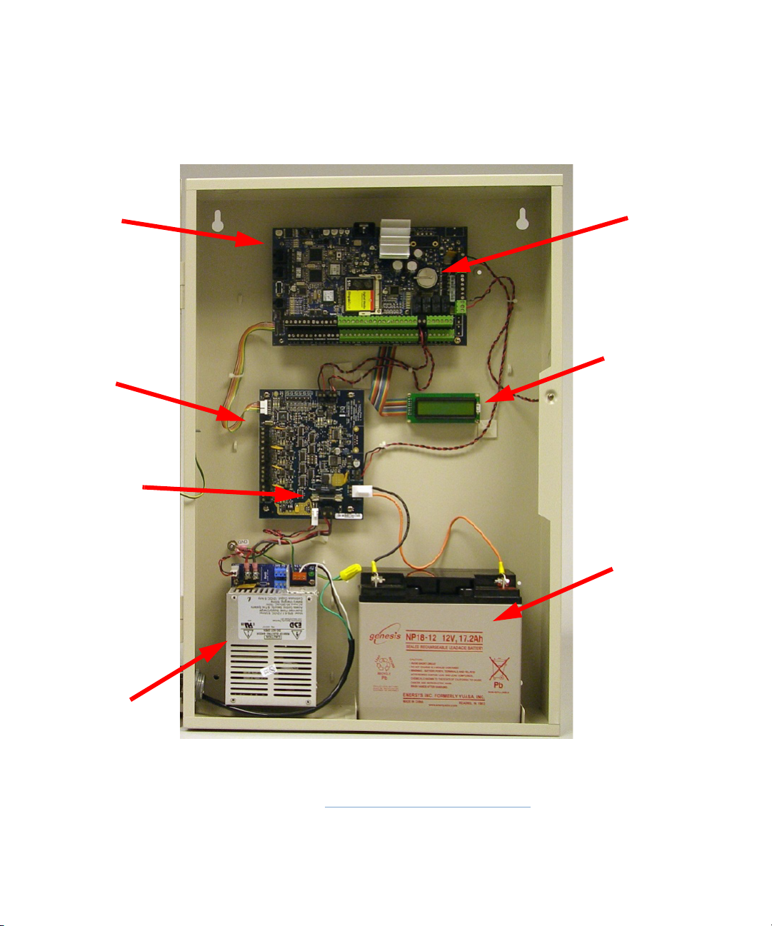
iSTAR eX Features
LCD
GCM
PMB
Lead -Acid
ESD Power
Supply
Fuse
Lithium
Battery
Battery
1–6 iSTAR eX Installation and Configuration Guide
Figure 1.1: iSTAR eX Hardware and Cabinet
iSTAR eX Features
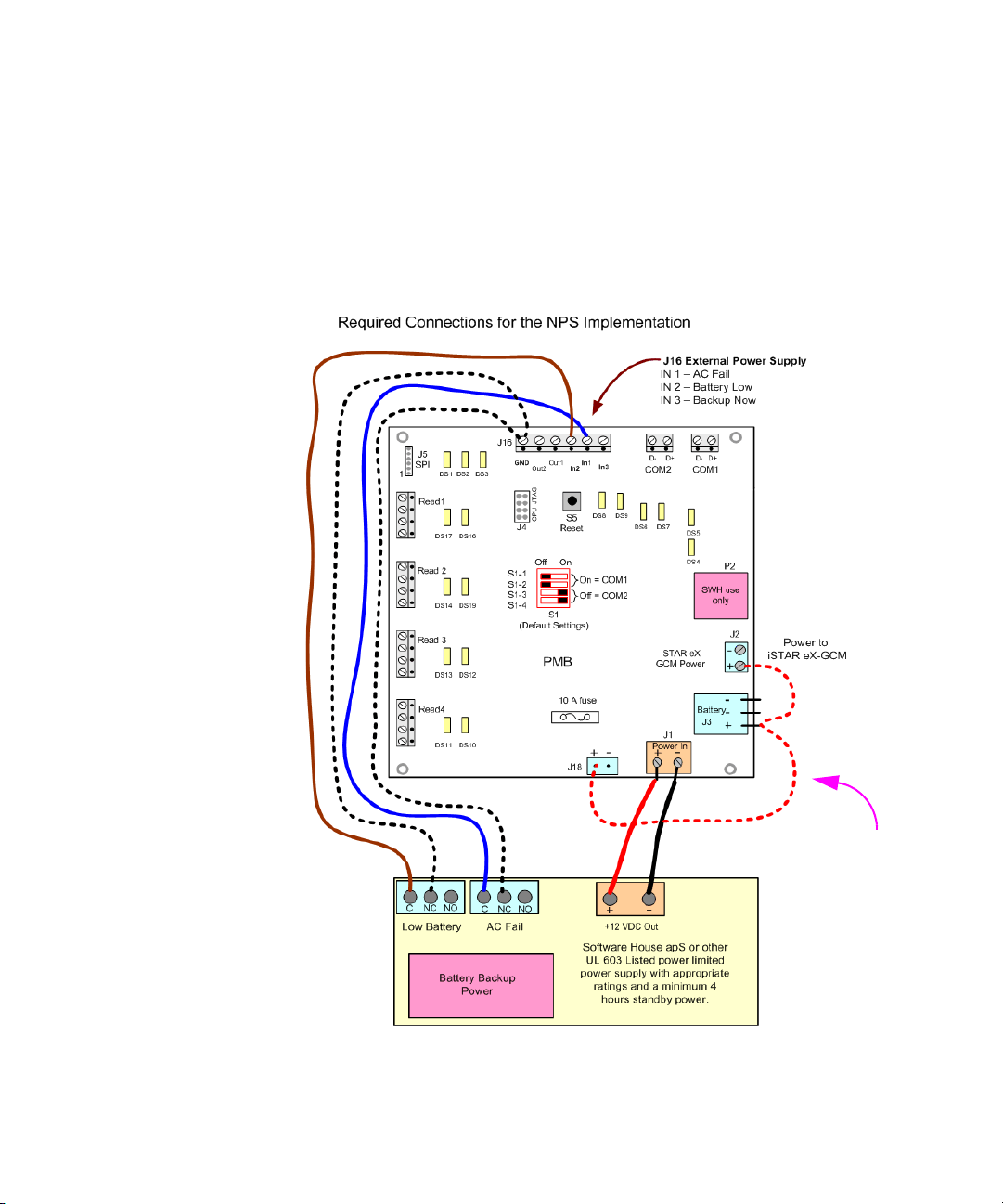
Note: The jumper from J2
to J3 to J18 is factory installed
on the NPS model.
Figure 1-2 illustrates how to wire the NPS version. Connect the following:
+12 VDC and Ground from External Power Supply to PMB J1. Observe polarity.
AC Fail to J16 - IN 1. Wire C and NC pins. There is no polarity.
Low Battery to J16 - IN 2. Wire C and NC pins. There is no polarity.
Verify Jumper from J2(+) to J3(+) to J18(+)
Figure 1-2: iSTAR eX NPS Power Connections
iSTAR eX Installation and Configuration Guide 1–7

iSTAR eX General Controller Module (GCM)
iSTAR eX General Controller Module (GCM)
The iSTAR eX GCM contains a 400 MHz PXA255 Microprocessor, a member
of the Intel XScale family of ARM processors that runs Microsoft Windows CE
5.0. Figure 1.3 on page 1-9 shows an iSTAR eX GCM.
Each iSTAR eX GCM contains:
an onboard CPU
two Ethernet ports (both are 10/100Base-T dual sensing)
onboard flash memory
onboard SDRAM memory
compact flash memory for storing primary and secondary backups
GCM Features
The iSTAR eX GCM supports:
LCD display area – provides iSTAR eX status and diagnostic messages
Multi-function rotary switch for board installation and diagnostics.
Memory components, including:
• Flash memory – to store iSTAR program data.
• On-board SDRAM (64MB) – storage capacity for card and event data.
• Compact flash memory.
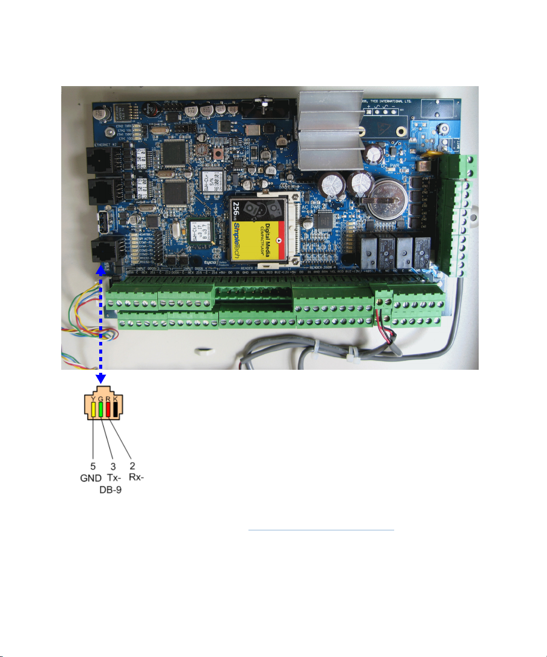
Figure 1.3 shows the iSTAR eX GCM and the pinout for a Diagnostic cable.
1–8 iSTAR eX Installation and Configuration Guide
iSTAR eX General Controller Module (GCM)
Diagnostic Cable
Figure 1.3: iSTAR eX GCM Photo
iSTAR eX Installation and Configuration Guide 1–9
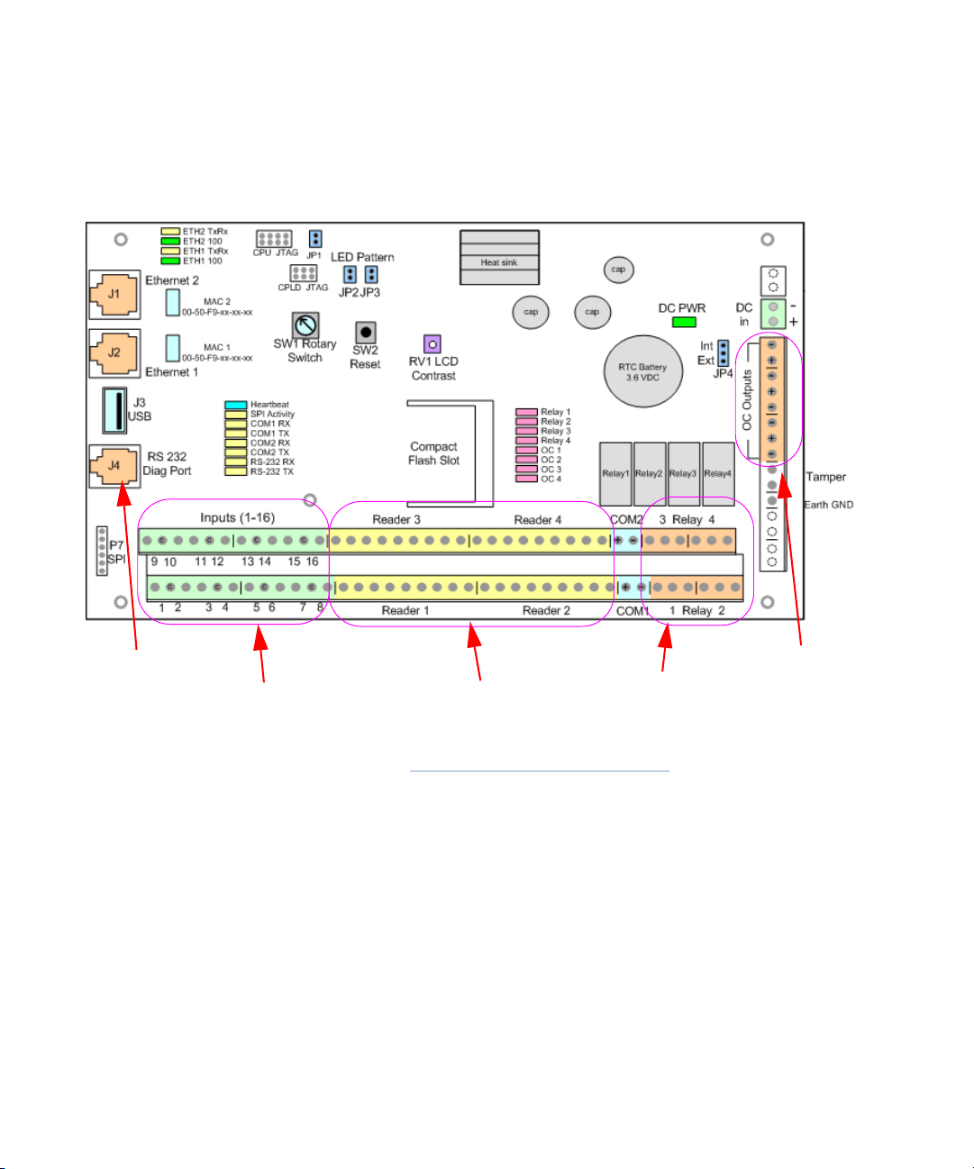
iSTAR eX General Controller Module (GCM)
16 General Purpose Inputs
4 Direct Wiegand Reader Ports
4 Relay Outputs
4 Open Collector Outputs
Diagnostic Cable Port
GCM Component Layout
Figure 1.3 shows the layout of the iSTAR eX GCM.
1–10 iSTAR eX Installation and Configuration Guide
Figure 1.4: iSTAR eX GCM Photo
 Loading...