

Tyco IR6003/7 Product User Manual
IR6003/7
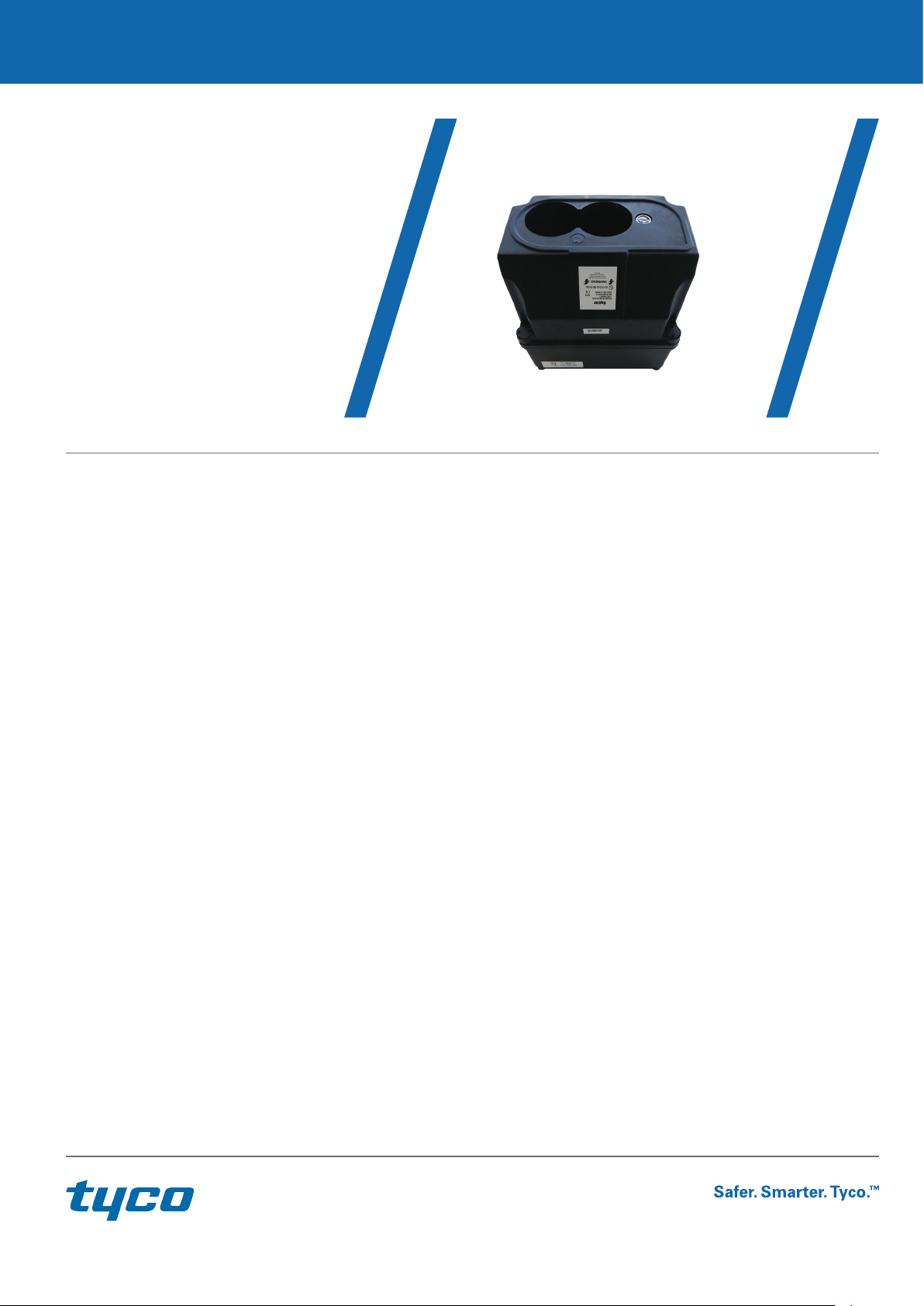
IR Oil Mist/Smoke
Detector
1 / 12
Product User Guide
Contents
1 Introduction 2
2 Features 2
2.1 Detector 2
2.2 P-UIM 2
3 Functional Description 3
3.1 Initialisation 3
3.2 Alarm Level Detection 3
3.3 Beam Blocked 3
3.4 Dual Automatic Compensation 3
4 Indications And Controls 4
4.1 Indicators 4
4.1.1 Detector 4
4.1.2 P-UIM 4
4.2 Controls 4
4.2.1 P-UIM 4
5 Installation 5
5.1 Detector Mounting Details 5
5.2 Detector Mounting Bracket 6
5.3 Detector Connection Details 7
5.4 Flying Lead Connections 7
5.4.1 Normal Operation 8
5.4.2 Hazardous Area Operation 8
5.5 P-UIM Mounting Details 8
5.5.1 Din Rail Mounting 8
5.5.2 Screw Mounting Details 9
6 Commissioning 11
7 Operating Parameters 11
7.1 Detector 11
7.2 P-UIM 11
8 Maintenance 12
9 Specification 12
9.1 Detector 12
Electrical 12
Mechanical 12
Environmental 12
9.2 P-UIM 12
Electrical 12
Mechanical 12
Environmental 12

2 / 12
1. Introduction
The Tyco Intelligent Oil Mist/Smoke Detector system consists of an IR6003/x Oil Mist/Smoke Detector and a 6005/x Power
Universal Interface Module (P-UIM).
The Oil Mist/Smoke Detector has been designed to be highly sensitive to the presence of Oil & Kerosene mists or smoke particles
in the path of the detector beam. The detector has been developed for use in enclosed oil rig wellheads areas, generator rooms
and turbine enclosures. The detector automatically compensates for contamination of the detector lenses and signals when a point
is reach where further deterioration cannot be tolerated and the lenses require cleaning. Two levels of alarm status are provided a
“Low” (pre-warning) and “High” level. Also a “Beam Blocked” status is provided in the event that the beam is interrupted.
The P-UIM, converts the output signals from the Oil Mist/Smoke Detector to 5 sets of volt free contacts, which provide the
detector status for the following conditions:
“Fault”
“Clean” (Clean detector lenses)
“Beam Blocked”
“Low” Level alarm
“High” Level Alarm
2. Features
2.1 Detector
Automatic Self-Calibration.
Range 2 to 30 metres.
Weather Proof to IP65.
Certified Intrinsically Safe.
Robust Design.
Heavy duty mounting bracket available.
Independent block output.
Cleaning status output.
Dual automatic compensation.
2.2 P-UIM
Wide operating voltage range; with internal voltage regulation.
Ability to accept direct input from the detector or input from the detector via a barrier.
Remote reset feature.
Alarm/Fault volt-free output contacts.
Local indication of P-UIM and Detector status.
Screw or DIN rail mounting.

3 / 12
3. Functional Description
3.1 Initialisation
When the detector is switched on the LED indicator flashes briefly to signify power-up. During the first 10-seconds the detector
performs auto-calibration to establish the quiescent obscuration level.
Note:
It is important that the beam path is cleared to a healthy state (no obscuration) prior to resetting the detector. If the beam path is
not healthy the detector will recalibrate to the current level of obscuration and may well report false alarm/fault conditions as the
path clears. If obscuration is high (dirty lenses or smoke/oil mist present) then the detector will not be able to establish an
operational state and will report a Clean fault (Clean LED pulses ON for 4 seconds) or a Life fault (Life LED is illuminated
continuously). The PUIM will latch the fault condition and the Detector/P-UIM will require resetting once the beam path is clear.
3.2 Alarm Level Detection
The detector monitors the obscuration level within the beam path and when it detects a loss of 0.5 dB it latches a low-level alarm
condition. If the loss is maintained within the 0.5 to < 1.5 dB band during the subsequent 15-second alarm condition monitoring
period, a low level alarm will then be reported (detector LED pulses ON/OFF for 30 seconds). If the loss exceeds 1.5 dB then a high
level alarm is latched and this status will be reported (detector LED pulses ON/OFF for 2 minutes) at the earliest at 8-seconds from
the beginning of the alarm condition monitoring period. If the high level occurs subsequent to the initial 8 seconds of the alarm
condition monitoring period and before a total of 15 seconds has elapsed, the high level alarm will be latched and reported
immediately.
It should be noted that if the level of loss during the alarm condition monitoring period falls below 0.5 dB. The latched alarm level
will be reset and the detector continues to monitor.
3.3 Beam Blocked
If the level of obscuration increases suddenly to a high level of loss a beam-blocked status will be latched and if the level is
maintained for 60 seconds, Beam Blocked will be reported (detector LED flashes ON for 2-seconds). If the beam-blocked level of
obscuration clears for more than a few seconds during the 1-minute beam-blocked condition-monitoring period, the detector
returns to its normal operating state.
3.4 Dual Automatic Compensation
The Detector automatically compensates for gradual detector lens contamination and also compensates for the more rapid
environmental changes (e.g. temperature change). The detector will report a CLEAN fault (detector LED flashes ON for 4 seconds)
once. If the detector is not cleaned it will continue to operate until a LIFE fault is detected (detector LED ON steady) at which point
the detector latches to an OFF condition. The detector must be cleaned and the reset once the LIFE fault has been detected.

4 / 12
4. Indications and Controls
4.1 Indicators
When the detector is switched on the LED indicator flashes briefly to signify power-up. During the first 10-seconds the detector
will latch the fault condition and the Detector/P-UIM will require resetting once the beam path is clear.
4.1.1 DETECTOR
DETECTOR – Red LED: Low Level Alarm - The LED pulses 0.5 sec ON, 0.5 sec OFF for 30 seconds.
High Level Alarm - The LED pulses 0.25 sec ON, 0.25 sec OFF for 2 minutes.
Life Fault – The LED is ON if the beam is blocked on power-up or reset and the detector fails to calibrate.
4.1.2 P-UIM
OUTPUT ON - Green LED: Indicates the supply is healthy. It extinguishes during the reset period.
OPEN – Red LED: Is lit when the detector connection is open circuit.
SHORT – Red LED: Is lit when the detector connection is short circuit.
LIFE – Red LED: Is lit flashing to indicate the P-UIM and Detector are both healthy.
Is lit steady to indicate a life fault
Is off for all other fault and alarm conditions.
CLEAN – Red LED: Is lit when a cleaning fault condition has been detected.
BEAM BLOCKED – Red LED: Is lit when a beam-blocked condition has been detected.
LOW – Red LED: Is lit when a Low Level Alarm has been detected.
HIGH – Red LED: Is lit when a High Level Alarm has been detected.
4.2 Controls
4.2.1 P-UIM
RESET (Top Panel): Pressing the RESET pushbutton will cause the system to restart.
RESET (Remote Input): The RESET input should be connected to the 24 V supply via a normally closed contact.
Open the reset contact for <1 sec will cause the P-UIM to reset.
Open the reset contact for >1 sec and <4 sec will cause the P-UIM and the IR Detector to
reset.
Open the reset contact for >4 sec will cause a fault.
 Loading...