


Tyan TITAN TURBO ATX-2 User Manual


Table of Contents
1. Introduction....................................................................... 4
Overview..................................................................... 4
Icons........................................................................... 5
Hardware Specifications/Features................................. 6
Software Specifications.................................................8
Technical Support......................................................... 8
Returning Merchandise for Service................................ 8
2. Board Installation.............................................................. 10
Unpacking.................................................................... 10
Installation.................................................................... 11
3. Onboard Resource Settings.............................................. 12
Quick References for Jumpers...................................... 12
Map of Motherboard Jumpers....................................... 14
CMOS RTC................................................................. 18
Soft Power Connector...................................................19
Sleep Button Connector.................................................19
Speaker Connector Installation...................................... 19
Power LED................................................................. 19
Hardware Reset Switch Connector Installation............... 19
Flash EEPROM........................................................... 20
Hardware CMOS & Password Reset............................ 20
DRAM Installation....................................................... 20
CPU Installation........................................................... 22
Cache Memory.............................................................23
Peripheral Device Installation........................................ 23
Connecting the Power Supply........................................ 24
4. BIOS Configuration........................................................... 26
Entering Setup.............................................................. 26
Control Keys................................................................ 27
Getting Help................................................................. 27
The Main Menu ........................................................... 27
Standard CMOS Setup Menu........................................ 30
BIOS Features Setup.................................................... 34
Chipset Features Setup................................................. 38
Power Management Setup............................................ 42
PnP/PCI Configuration................................................. 45

Load BIOS Defaults..................................................... 48
Load Setup Defaults..................................................... 49
Integrated Peripherals................................................... 50
Supervisor Password and User Password...................... 53
IDE HDD Auto Detection............................................. 54
Save & Exit Setup........................................................ 55
Exit Without Saving....................................................... 56
5. Flash Writer Utility............................................................ 58
Flash Memory Writer.................................................... 58
The Flash Memory Writer Utility Screen........................ 60
6. System Resources............................................................. 62
Timer and DMA Channel Maps..................................... 62
Interrupt Map............................................................... 63
POST Messages.......................................................... 63
POST Codes................................................................ 67
Chapter 1
chapter 1
Introduction
Overview
The S1573S is a quality, high performance mainboard designed for Intel
Pentium microprocessors. This mainboard utilizes the Intel 430TX
chipset and can support CPU speeds of 75MHz through 233MHz. The
S1573S will also support the Cyrix M1/6x86 and M2/6x86MX CPU’s,
the AMD K5/K6 CPU’s, and the Intel multimedia Pentium P55C and
P54CTB (MMX Overdrive) CPU’s.
The S1573S’s PCI Local Bus provides high performance capabilities
that are ideal for a wide range of demanding applications such as CAD,
CAM, CAE, networking, multi-user environments, database management, desktop publishing, image processing and 3D animation.
This integrated system board achieves high reliability with numerous
features and yet is small enough to be supported in an ATX formfactor. Some of the features included are onboard dual channel PCI
PIO, BUS Master IDE and UltraDMA/33, onboard floppy controller,
onboard high speed I/O, and support for pipeline-burst SRAM.
4
Flexibility and expandability have been designed into the S1573S. With
I/O and drive controller support built onboard, the five PCI and three
ISA slots (one ISA and one PCI as a shared slot) are free for numerous add-on expansion cards.
Remember to take a look at TYAN Computer’s web site located at
http://www.tyan.com. There you can find information on all of TYAN’s
products along with FAQs, distributors list, drivers and CMOS setting
explanations. If you have a tech support question please contact us at
www.tyan.com.
Icons
In order to help you navigate this manual and set up your system, we
have added several icons to our format.
This icon alerts you to particularly important details regarding the setup or maintenance of your system. This icon often
!
appears next to information that may keep you from damaging your board or system. While we will often point out the most vital
paragraphs in a chapter, you should always read every word in the text.
Failing to do so can lead to exasperation and expense.
INTRO
Wherever possible, we have included step-by-step instructions for setting up your system, which are indicated by this
icon. However, it is in your best interest to read an entire
section (and perhaps the entire manual) before you begin to alter the
settings on your motherboard.
While we have alerted you to potential dangers in several
places in this manual with this icon, these warnings should
not be regarded as the whole of your safety regimen.
Never forget that computers are electrical devices, and are capable of
delivering a burn or shock. Prevent damage to yourself and to your
board: always ensure that your system is turned off and unplugged
whenever you are working with it, and that you are equipped with a
static safety device.
5

Chapter 1
Hardware Specifications/Features
Processor Information sZIF Socket #7.
s50-83MHz BUS support (see
disclaimer on page 18).
sPentium/Pentium MMX 75-233MHz.
sAMD K5/K6 75MHz-233MHz.
sCyrix/SGS/IBM 6x86 P120+ to
P200+ (see disclaimer on page 18).
sCyrix 6x86MX support built-in (see
disclaimer on page 18).
Chipset Information sIntel 430TX PCIset.
sFifth generation Pentium chipset.
Voltage and Power sDesign incoporates ATX power
Information supply connector.
s12 V power source for DC fan
onboard.
s3.3V or 5.0V DRAM support.
sSwitching Power Supply onboard.
Main Memory sUp to 256MB on board.
sSix 72-pin SIMM sockets.
sTwo 168-pin DIMM sockets.
sEDO or FPM SIMM support.
sEDO DIMM and SDRAM support.
System Management sWake-on LAN connector.
sOptional LM75 CPU temperature-
sensing chip.
sOptional National LM78 thermal, fan
and heat monitoring chip.
sOptional Intel LANDesk Client
Manager software, and/or Intel
LANDesk Server Manager software
(with LM78 installed).
6

Expansion Slots sFive 32-bit PCI Bus Master slots.
sThree 16-bit ISA slots.
sOne shared, seven usable.
Physical Dimensions sATX design.
s8.3 x 12 inches.
BIOS Information sAward Plug and Play flash BIOS.
sDeep Green and Energy Star
compliant.
sACPI, Year 2000, and PC97/98
compliant.
sSoft power-down, multiple boot
options.
sWin98 Ready, DMI 2.0 compliant.
sSupport for easy BIOS upgrades with
flash EEPROM chip.
Disk Drive & System I/O sTwo PCI Bus Mastering EIDE
channels.
sSupports EIDE CD-ROMs.
sPIO Mode 3 & 4 (up to 17MB/sec
DTR).
sUltraDMA33 Bus Mastering Mode
(up to 33MB/sec DTR).
sTwo floppy drives (up to 2.88MB).
sTwo ATX serial ports (16550
UARTs).
sOne ATX ECP/EPP parallel port.
sOne IR (InfraRed) I/O interface
port.
sTwo USB rev 1.2 (universal serial
BUS) ports.
sOne ATX PS/2 mouse port
connector.
sOne ATX PS/2 keyboard connector.
INTRO
7

Chapter 1
Software Specifications
Operating System sOperates with MS-DOS, Windows
3.x, Windows for WorkGroups 3.x,
Windows 95, Windows NT, OS/2,
Novell Netware, Solaris, and SCO
Unix.
Information presented in this publication has been carefully checked for
reliability. However, no responsibility is assumed for inaccuracies. The
information contained in this document is subject to change without
notice.
Technical Support
If a problem arises with your system, you should first turn to your
dealer for help. Your system has most likely been configured by them,
and they should have the best idea of what hardware and software
your system contains. Hence, they should be able to be of the most
assistance. Further, if you purchased your system from a dealer near to
you, you can actually bring your system in to them to have it serviced,
instead of attempting to yourself (which can have expensive consequences). If your dealer is unable to assist you:
Try our web page – http:// www.tyan.com,
or user newsgroup – alt.comp.periphs.mainboard.tyan.
Returning Merchandise for Service
During the warranty period, contact your distributor or system vendor
FIRST for any product problems. This warranty only covers normal
customer use and does not cover damages incurred during shipping or
failure due to the alteration, misuse, abuse, or improper maintenance of
products.
8

For Resellers Only:
A receipt or copy of your invoice marked with the date of purchase is
required before any warranty service can be rendered. You can obtain
service by calling the manufacturer for a Return Merchandise Authorization (RMA) number. The RMA number should be prominently
displayed on the outside of the shipping carton and the package should
be mailed prepaid, or hand-carried to the manufacturer. Shipping and
handling charges will be applied for all orders that must be mailed when
service is complete.
Trademarks
Award BIOS/Flash are trademarks of Award Software International,
Inc.
Windows is a trademark of Microsoft Corporation.
IBM, PC, AT, PS/2 are trademarks of IBM Corporation.
INTEL, Pentium are trademarks of Intel Corporation.
Titan Turbo S1573S ATX-2 is a trademark of TYAN Computer
Corporation.
All other trademarks are the property of their respective companies.
INTRO
9
Chapter 2
chapter 2
Board Installation
Unpacking
The mainboard package should contain the following:
• S1573S Mainboard
• One IDE 40 pin cable
• One 34 pin floppy cable
• User’s Manual
The mainboard contains sensitive electric components which can be
easily damaged by static electricity, so the mainboard should be left in
its original packaging until it is ready to be installed.
With the power supply plugged in and turned off, touch an unpainted
area of the system chassis immediately before handling the mainboard
or any component. Doing so discharges any static charge your body
may have acquired.
After opening the mainboard carton, extract the system board-holding it
by its edges-and place it on a grounded anti-static surface, component
side up. Inspect the board for damage. Press down on any of the
10

socket ICs if it appears that they are not properly seated (the board
should still be on an anti-static mat). Do not touch the bottom of the
board.
DO NOT APPLY POWER TO THE BOARD IF IT HAS BEEN
!
DAMAGED!
Installation
You are now ready to install your mainboard. The mounting hole pattern
of the S1573S matches the ATX system board specifications. Your
chassis should be that of a standard ATX mainboard form factor.
INSTALL
11
Chapter 3
chapter 3
Onboard Resource Settings
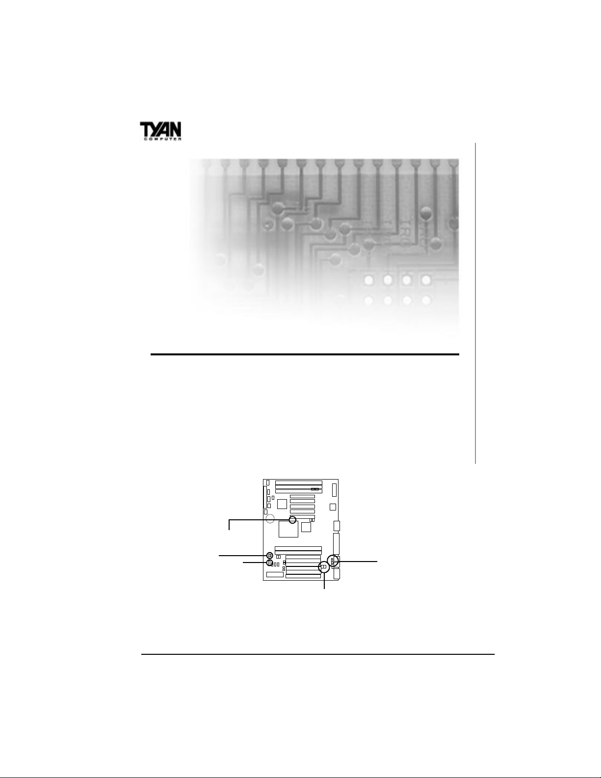
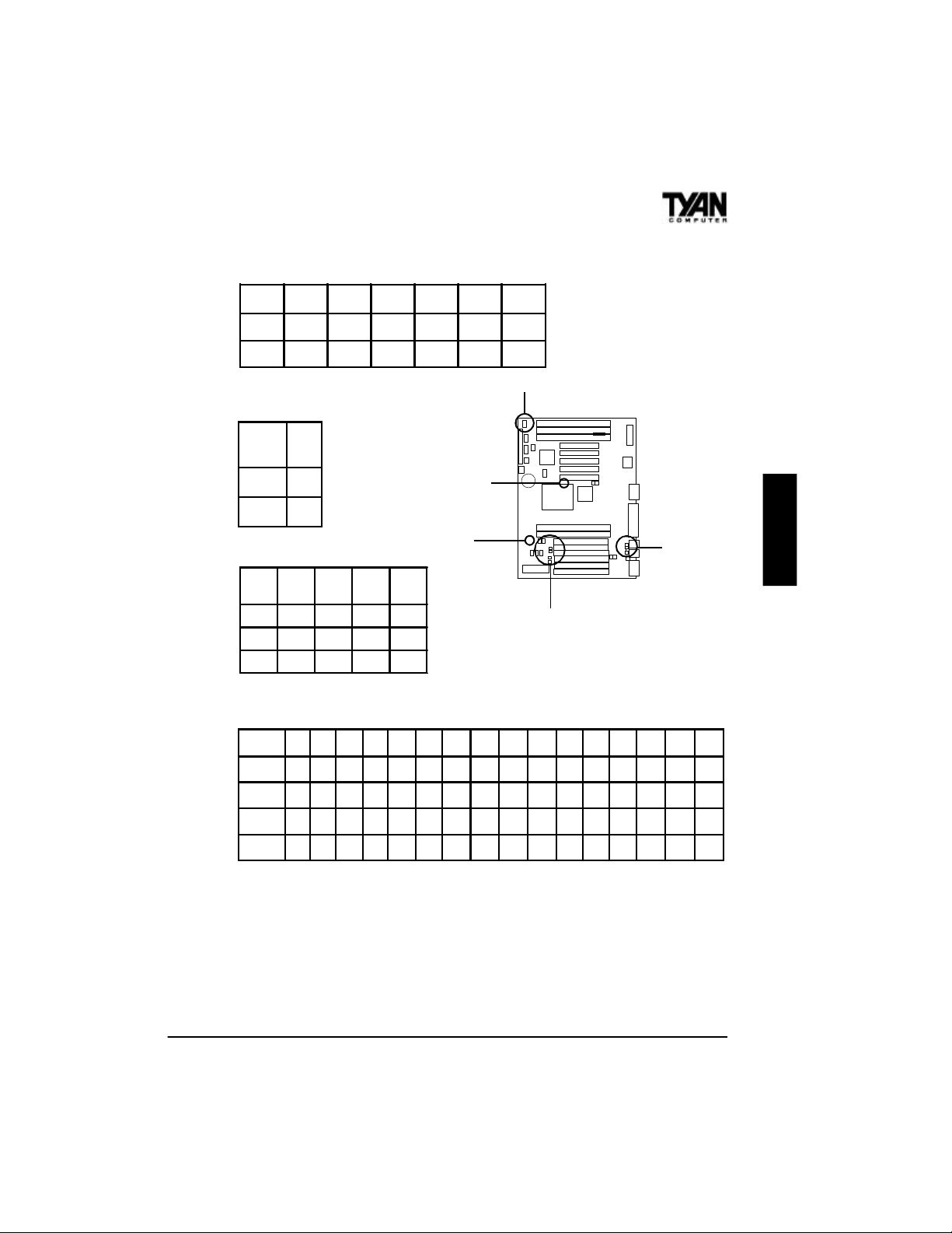
Quick References for Jumpers
The following tables will help you set the jumpers for CPU speed, BUS
frequency, and memory voltage, among others. For CPU settings, you
may want to refer first to the more comprehensive chart on page 13. The
miniature motherboard maps will help you locate the jumpers on your
board. A full-page map of the motherboard can be found on page 14.
BF0, BF1
J31, BF2
J23
^ Some boards may not have JP26.
VID1-VID4
JP24-26^
12
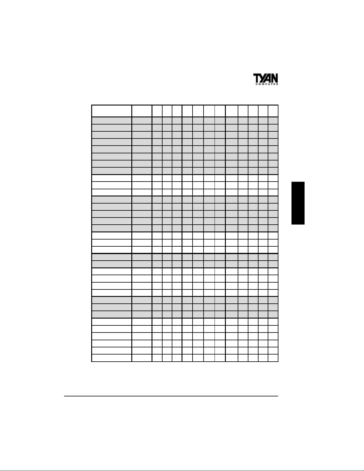
Jumper Settings by CPU Type
CPU
Intel P54C 75 50MHz x 1.5 OFF OFF OFF OFF ON ON ON 1-2,3-4 ON OFF OFF OFF
Intel P54C 90 60MHz x 1.5 OFF OFF OFF OFF ON ON ON 1-2 OFF OFF OFF OFF
Intel P54C 100 66MHz x 1.5 OFF OFF OFF OFF ON ON ON open OFF OFF OFF OFF
Intel P54C 120 60MHz x 2 ON OFF OFF OFF ON ON ON 1-2 OFF OFF OFF OFF
Intel P54C 133 66MHz x 2 ON OFF OFF OFF ON ON ON open OFF OFF OFF OFF
Intel P54C 150 60MHz x 2.5 ON ON OFF OFF ON ON ON 1-2 OFF OFF OFF OFF
Intel P54C 166 66MHz x 2.5 ON ON OFF OFF ON ON ON open OFF OFF OFF OFF
Intel P54C 200 66MHz x 3 OFF ON OFF OFF ON ON ON open OFF OFF OFF OFF
Intel P55C 166 MMX 66MHz x 2.5 ON ON OFF OFF OFF OFF ON open OFF ON ON ON
Intel P55C 200 MMX 66MHz x 3 OFF ON OFF OFF OFF OFF ON open OFF ON ON ON
Intel P55C 233 MMX 66MHz x 3.5 OFF OFF OFF OFF OFF OFF ON open OFF ON ON ON
AMD K5 90 60MHz x 1.5 OFF OFF OFF ON ON ON ON 1-2 OFF OFF OFF OFF
AMD K5 100 66MHz x 1.5 OFF OFF OFF ON ON ON ON open OFF OFF OFF OFF
AMD K5 120 60MHz x 2 ON OFF OFF ON ON ON ON 1-2 OFF OFF OFF OFF
AMD K5 133 66MHz x 2 ON OFF OFF ON ON ON ON open OFF OFF OFF OFF
AMD K5 166 66MHz x 2.5 ON ON OFF ON ON ON ON open OFF OFF OFF OFF
AMD K6 166 66MHz x 2.5 ON ON OFF ON OFF OFF ON open OFF ON ON ON
AMD K6 200 66MHz x 3 OFF ON OFF ON OFF OFF ON open OFF ON ON ON
AMD K6 233 66MHz x 3.5 OFF OFF OFF OFF OFF ON ON open OFF ON ON ON
IDT C6 150 50MHz x 3 OFF ON OFF ON OFF ON ON 1-2,3-4 ON OFF OFF OFF
IDT C6 180 60MHz x 3 OFF ON OFF ON OFF ON ON 1-2 OFF OFF OFF OFF
Cyrix PR120+ 6x86 50MHz x 2 ON OFF OFF ON OFF ON ON 1-2,3-4 ON OFF OFF OFF
Cyrix PR150+ 6x86 60MHz x 2 ON OFF OFF ON OFF ON ON 1-2 OFF OFF OFF OFF
Cyrix PR166+ 6x86 66MHz x 2 ON OFF OFF ON OFF ON ON open OFF OFF OFF OFF
*Cyrix PR200+ 6x86 75MHz x 2 ON OFF OFF ON OFF ON ON 3-4 OFF OFF OFF OFF
Cyrix PR150+ 6x86L 60MHz x 2 ON OFF OFF OFF OFF OFF ON 1-2 OFF ON ON ON
Cyrix PR166+ 6x86L 66MHz x 2 ON OFF OFF OFF OFF OFF ON open OFF ON ON ON
*Cyrix PR200+ 6x86L 75MHz x 2 ON OFF OFF OFF OFF OFF ON 3-4 OFF ON ON ON
#Cyrix PR166+ 6x86MX 60MHz x 2.5 ON ON OFF ON OFF OFF ON 1-2 OFF ON ON ON
#Cyrix PR166+ 6x86MX 66MHz x 2 ON OFF OFF ON OFF OFF ON open OFF ON ON ON
#Cyrix PR200+ 6x86MX 66MHz x 2.5 ON ON OFF ON OFF OFF ON open OFF ON ON ON
#*Cyrix PR200+ 6x86MX 75MHz x 2 ON OFF OFF ON OFF OFF ON 3-4 OFF ON ON ON
#Cyrix PR233+ 6x86MX 66MHz x 3 OFF ON OFF ON OFF OFF ON open OFF ON ON ON
#*Cyrix PR233+ 6x86MX 75MHz x 2.5 ON ON OFF ON OFF OFF ON 3-4 OFF ON ON ON
BUS speed
& multiplier
BF0 BF1 BF2 VID1 VID2 VID3 VID4 J23 J31 JP24 JP25
*See disclaimer on page 18. ^ Some boards may not have JP26.
# Check the face of your CPU for BUS speed.
The VID1-VID4 settings for Cyrix 6x86L series will vary. Some of the CPUs in this series are
2.8V, and others are 3.3V. Check the face of the CPU and the CPU Voltage Settings table for the
proper settings for these jumpers.
JP26
^
ONBOARD
13
Chapter 3
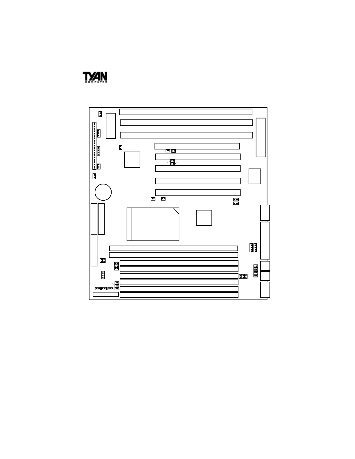
Map of Motherboard Jumpers
JP2
1
J8
24
22
J2
1
18
13
J25
10
1
8
1
3
FAN2
1
JP1
1
3 volt
battery
1
Primary IDE
Secondary IDE
1
Floppy connector
J31 BF2
1
FAN1J30
1
power connector
1
J23
FAN3
JP27
JP18
JP21
JP20
BIOS
JP19
JP281 1
J90
82371AB
BF0
CPU
J33 J34
J32
BF1
DIMM Bank 0
DIMM Bank 1
SIMM Socket 0
SIMM Socket 1
SIMM Socket 2
SIMM Socket 3
SIMM Socket 4
SIMM Socket 5
ISA slot 3
ISA slot 2
ISA slot 1
PCI slot 5
PCI slot 4
J35
PCI slot 3
PCI slot 2
PCI slot 1
82439TX
1
JP15
JP16
1
JP24
Keyboard controller
SMC I/O
J14
J10
J11
J17
1
1
J19
VID4
VID3
VID2
VID1
JP25
J21
JP26
J22
The tiny “1”s next to jumpers of 3 pins or more indicate the position of
pin 1 for that jumper. Refer to pages 15-17 for the jumper and pin
assignments.
14
J2 Infrared connector
CON1
Wake-on LAN
J10, J11 USB connectors
J25 Keylock
JP1 VBAT
CPU Temperature Sensor
J15 Primary IDE
J13 Secondary IDE
FAN
J16 Floppy connector
J20
ATX power connector
Pin Assignments
1 2 3 4 5
J2 (IR)
J10, J11 (USB)
CON1 (Wake-on LAN)
FAN1-FAN3
RX GND TX VCC --
VCC Data Data GND Not used
VCC GND Wake -- --
GND VCC Fan Monitor -- --
168-pin DIMM
72-pin SIMM
PS/2 keyboard
J21
(-- indicates pin is absent)
J22
ONBOARD
J14 COM2
J17 LPT1 J19 PS/2 mouse
COM1
15
Chapter 3
BUS Settings
BUS
Frequency
50MHz
1-2, 3-4 ON
J23 J31
*Notes: Please ignore the BUS speed settings
printed on the motherboard. Please see the warning
regarding 75MHz and 83MHz BUS speeds on page
18.
60MHz
66MHz
75MHz
83MHz
1-2 OFF
OPEN OFF
3-4 OFF
1-2, 3-4 OFF
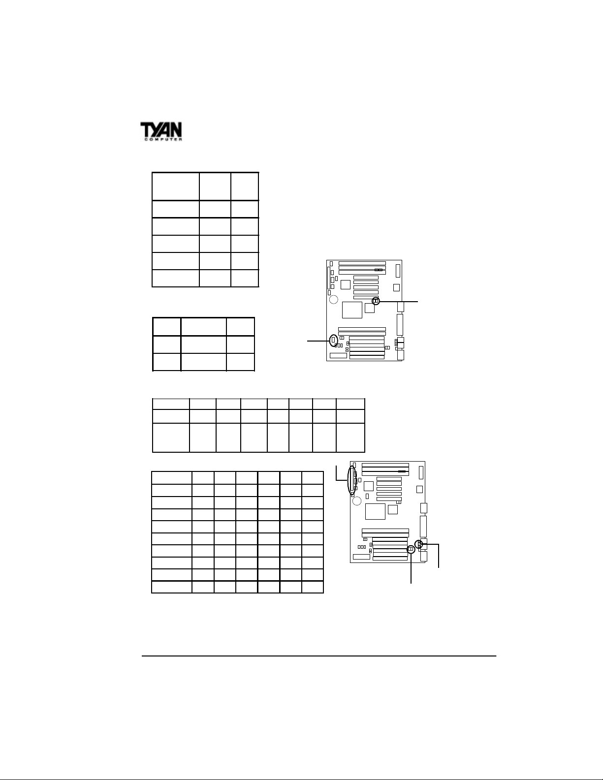
JP15 and JP16 Settings
1-2 2-3
JP15
JP16
COM PORT IR
COM PORT IR
J23, J31
J8 Settings
Pins 1-2 3-4 6-11 13-14 18-20 22-23 24-27
Function
Assignment
Power
On/Off
1=VCC
2=GND
Sleep InfraRed
6=VCC
8=IR RX
3=GND
9=GND
4=Sleep
10=IR TX
11=VCC
IDE
LED
13=+
14=-
Power
LED
18=VCC
20=LED
Reset Speaker
22=GND
23=Reset
CPU Model Settings
CPU VID1 VID2 VID3 VID4 JP24 JP25
P54C OFF ON ON ON OFF OFF
P55C OFF OFF OFF ON ON ON
K5 ON ON ON ON OFF OFF
K6-166 ON OFF OFF ON ON ON
K6-200 ON OFF OFF ON ON ON
K6-233 OFF OFF ON ON ON ON
Cyrix 6x86 * * * * OFF OFF
Cyrix 6x86L * * * * ON ON
Cyrix 6x86MX * * * * ON ON
24=VCC
25=GND
27=Speaker
J8
JP15, JP16
VID1-VID4
JP24, JP25
*For Cyrix settings, please refer to the CPU Voltage table on page 13. For all CPUs,
please refer to the BUS Settings and CPU Speed Settings tables. JP24 and JP25 should
be set to OFF for P54C, K5, 6x86 CPUs, and ON for P55C, K6, 6x86L, 6x86MX
CPUs.
16
SIMM Memory Voltage Settings
VCC JP18 JP19 JP28 JP20 JP21 JP27
3.3V
OFF OFF OFF ON ON ON
ON ON ON OFF OFF OFF
5V
BIOS Memory Voltage Settings
BIOS
CPU Multipliers
Mult.
JP2
VCC
1-2
5V
12V
CPU
BF0
BF1
BF2
2-3
x1.5 x2 x2.5 x3
OFF ON ON OFF
OFF OFF ON ON
OFF OFF OFF OFF
BF0, BF1
BF2
CPU Voltage Settings
CPU VCC 2.0V 2.1V 2.2V 2.3V
OFF ON OFF ON OFF ON OFF ON OFF ON OFF ON OFF ON OFF ON
VID1
OFF OFF ON ON OFF OFF ON ON OFF OFF ON ON OFF OFF ON ON
VID2
OFF OFF OFF OFF ON ON ON ON OFF OFF OFF OFF ON ON ON ON
VID3
OFF OFF OFF OFF OFF OFF OFF OFF ON ON ON ON ON ON ON ON
VID4
2.4V 2.5V 2.6V 2.7V 2.8V 2.9V 3.0V 3.1V 3.2V 3.3V 3.4V 3.5V
JP2
ONBOARD
VID1-VID4
JP18-21
17
Chapter 3
Windows 95 Users:
You may encounter problems with some of the devices in the Intel
82371AB chipset. Neither the PCI Bridge nor the PCI Universal Serial
BUS device IDs for this chipset (also called PIIX4) are recognized by
Windows 95. This is a software problem, not a hardware problem, and
can be easily remedied by either upgrading to Windows 98 or downloading the 82371AB patch found at http://www.tyan.com or at ftp://
download.intel.com/design/pcisets/busmastr/setupex.exe. (Note: USB
requires Windows 95 OSR 2.1 or above; please contact Microsoft for
USB update.)
Disclaimer:
!
This motherboard incorporates support for 75MHz and 83MHz BUS
speeds. However, these speeds will push PCI bandwidth beyond the Intelrecommended specification for PCI 2.1 compliance. Therefore, TYAN
Computer Corporation takes no responsibility for any problems, be they
hardware or software, related to the use of BUS speeds beyond 66MHz.
We also cannot guarantee any PCI cards’ compatibility beyond the specified speed of 33MHz. Technical support and RMA/Warranty claims relating to the use of BUS speeds beyond the 66MHz/33MHz limit recommended by Intel will not be honored by TYAN. Use at your own risk.
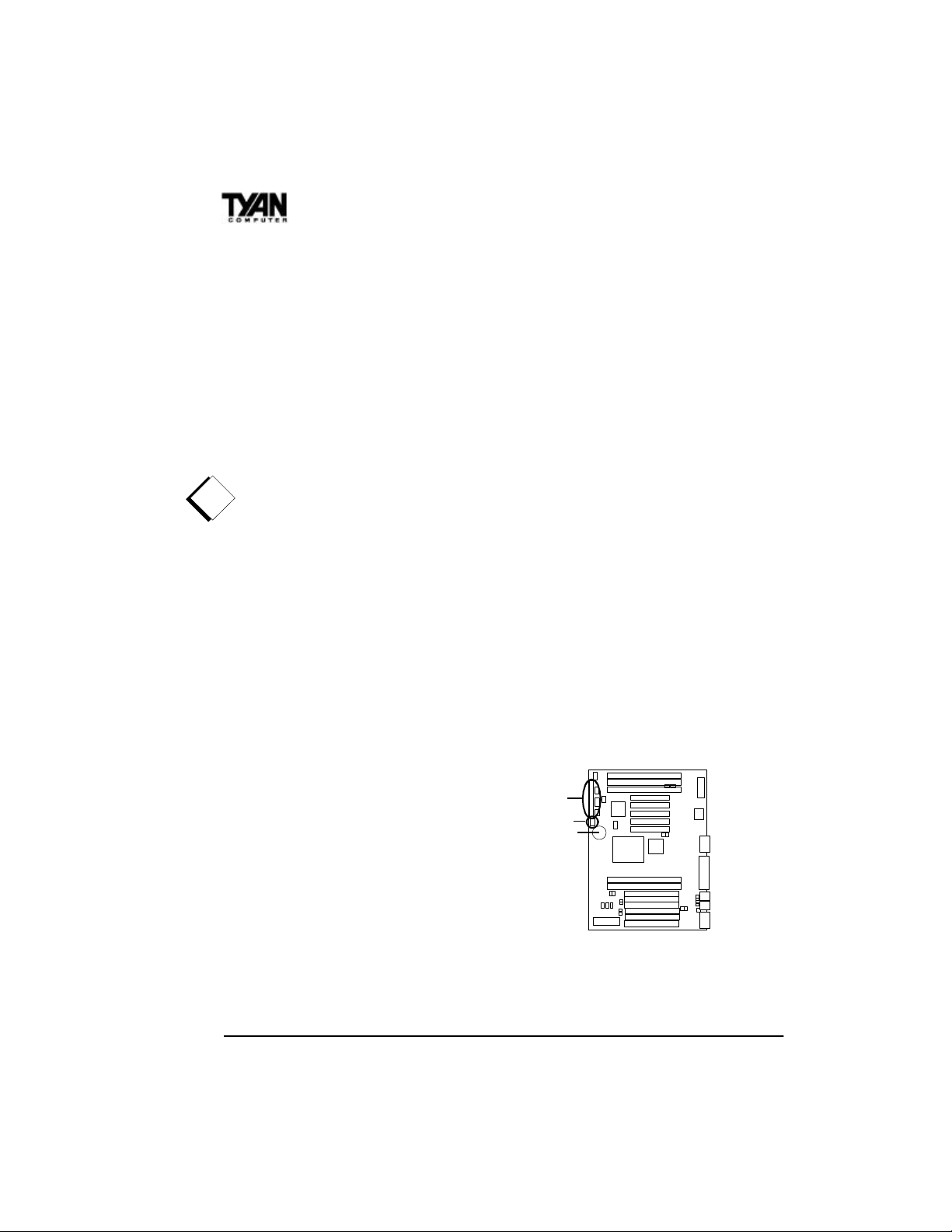
CMOS RTC
The 430TX chipset includes an internal
battery and Real Time Clock circuit. The
RTC provides the date and time for the
system. If the battery is low, it will
prevent your system from POSTing, and
you will not get a display. Normally the
life span of an RTC internal battery is 10
years, but if yours is running low, you will
need to replace it with a new 3V lithium
battery (Duracell DL2032).
18
J8
JP1
battery

Soft Power Connector
The Soft Power Connector is located on pins 1 and 2 of jumper block
J8. Pressing the Soft Power Button will turn the system on (and off). If
you hold this button down for more than four seconds, the chipset will
shut down, but the power will remain on. Pressing the button again will
reboot the system.
Sleep Button Connector
The sleep button connector is located on pin 3 and pin 4 of jumper block
J8. Pressing this button once will put the system in Sleep (or Suspend)
mode. Pressing this button again will wake the system up.
Speaker Connector Installation
The S1573S provides a 4-pin header to connect the speaker. The
speaker is connected to pins 24-27 on jumper block J8.
Power LED
The power LED is lit when the system is on, is not lit when the system
is off, and blinks when the system is in Sleep (or Suspend) mode.
External SMI
The external SMI is located at jumper J90. The pin assignment is pin1:
external SMI; pin 2: GND.
Hardware Reset Switch Connector
ONBOARD
Installation
The Reset switch on your case’s display panel provides you with the
Hardware Reset function, which is the same as power on/off. The
19

Chapter 3
system will do a cold start after the Reset button is pushed. The Reset
switch is a 2-pin connector and should be installed on pins 22 and 23 on
jumper block J8.
Flash EEPROM
The S1573S uses flash memory to store BIOS programs. It can be
updated as new versions of the BIOS become available. The flash
utility will guide you through the update process step by step (see
Chapter 5).
JP2 determines which type of EPROM is used. This jumper has been
set to match the onboard BIOS chip. The factory default for the
S1573S is on pins 1-2. Depending on the type of EPROM used, some
boards will have JP2 on pins 2-3.
Hardware CMOS & Password Reset
If you have been locked out of your system because you forgot your
password or set the CMOS incorrectly, follow the instructions below.
1. Power off the system
2. Set jumper JP1 to pins 2 and 3 (see previous page for
location of JP1).
3. Wait for 2 seconds, then return jumper JP1 to pins 1 and 2.
4. Power on the system again.
By following this procedure, you will erase your password and reset the
CMOS to the BIOS defaults.
DRAM Installation
The S1573S uses a 64-bit data path from memory to CPU and can
accommodate up to 256MB of RAM. The mainboard supports Fast
Page Mode and EDO (Extended Data Out) 72-pin SIMMs. SDRAMs
(Synchronous DRAMs) are also supported in the DIMM slots. DIMMs
must be of the unbuffered variety. The position of the notch in the
!
DRAM Key Position will tell you whether or not a DIMM is unbuf-
20
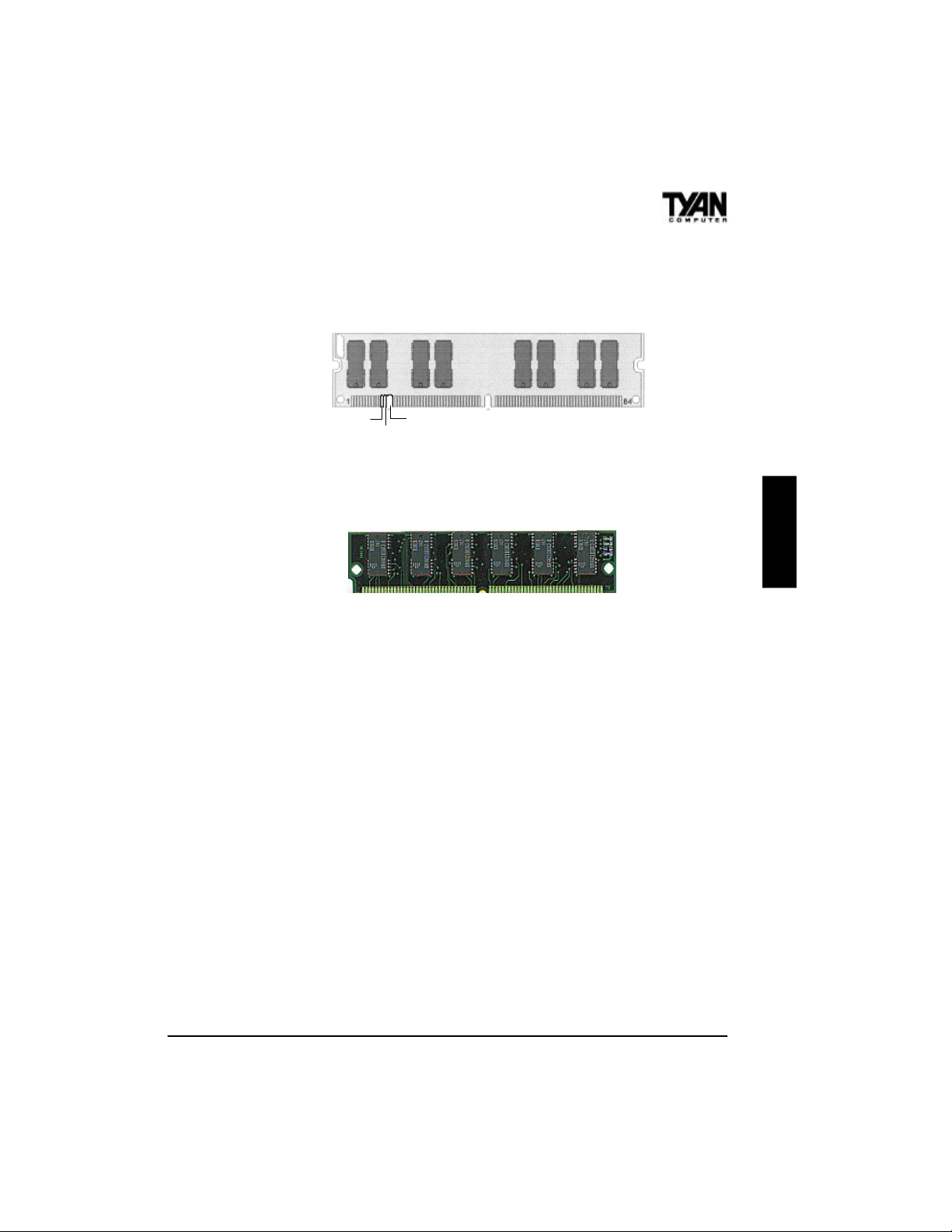
fered (see figure below). All installed memory will be automatically
detected, so there is no need to set jumpers. The TX chipset can cache
up to 64MB of RAM.
RFU
Buffered
Unbuffered
168-pin DIMM
Make sure you do not attempt to install a 168-pin DIMM (shown
above) in a socket designed for a 72-pin SIMM (shown below), or viceversa.
72-pin SIMM
Some details of memory installation:
s SIMM modules must be installed in pairs.
s Each pair of SIMMs must be of the same size and type.
s The mainboard supports 4MB, 8MB, 16MB, 32MB, and 64MB
SIMMs.
s SIMM banks 0, 1, and 2 can use either double- or single-sided
SIMMs.
s Two SIMMs or one unbuffered DIMM must be installed for the
system to POST.
s The mainboard supports 16MB, 32MB, and 64MB DIMM mod-
ules.
s SIMM bank 0 and DIMM bank 0 cannot be used at the same time.
s SIMM bank 1 and DIMM bank 1 cannot be used at the same time.
s You can use SIMM bank 0 with DIMM bank 1.
s You can use SIMM bank 1 with DIMM bank 0 (see motherboard
map on page 14).
s If you use 4MBx64 DIMMs you cannot use SIMM bank 2.
s We do not recommend using SIMM bank 2 along with DIMMs.
ONBOARD
21
Chapter 3
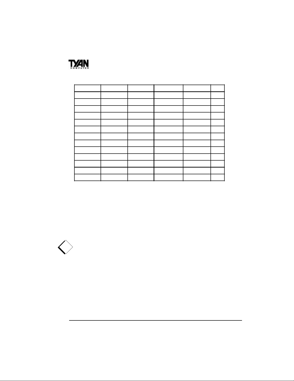
The table below shows some of the possible memory configurations.
SIMM Bank 0 SIMM Bank 1 SIMM Bank 2 DIMM Bank 0 DIMM Bank 1 Total
4MBx2 0 0 0 0 8MB
0 0 0 8MBx1 0 8MB
0 0 0 16MBx1 0 16MB
8MBx2 0 0 0 0 16MB
4MBx2 4MBx2 4MBx2 0 0 24MB
16MBx2 0 0 0 0 32MB
0 8MBx2 0 16MBx1 0 32MB
32MBx2 0 0 0 0 64MB
0 0 0 0 64MBx1 64MB
0 0 0 32MBx1 64MBx1 96MB
0 0 0 64MBx1 64MBx1 128MB
64MBx2 0 0 0 64MBx1 192MB
0 0 0 128MBx1 128MBx1 256MB
CPU Installation
Several types of CPUs (75 through 233MHz) can be used on the
S1573S. Please refer to page 13 for the correct CPU jumper settings
for your board.
Remember:
s The CPU is a sensitive electronic component and it can easily be
!
damaged by static electricity. Do not touch the CPU pins with your
fingers.
s When installing the CPU into the socket, match the CPU pins to
the socket pins. Note that one corner of the socket’s top is different from the other three corners. Likewise, one corner of the
CPU’s bottom is different from the other three corners. Line the
unique socket corner up with the unique CPU corner.
s Before the CPU is installed, the mainboard must be placed on a flat
surface. You should be able to insert the CPU with minimal, but
firm, pressure. Do not press down hard on the CPU.
22