

Tyan TIGER I7505 User Manual

Tiger i7505
///
S2668
Revision 1.00
Copyright © TYAN Computer Corporation, 2002 - 2003. All rights reserved. No part of this manual
may be reproduced or translated without prior written consent from TYAN Computer Corp.
All registered and unregistered trademarks and company names contained in this manual are
property of their respective owners including, but not limited to the following.
TYAN, Tiger i7505 S2668 are trademarks of TYAN Computer Corporation.
Intel, Xeon, and combinations thereof are trademarks of Intel Corporation.
Microsoft and Windows are trademarks of Microsoft Corporation.
Phoenix BIOS is a trademark of Phoenix Technologies.
Winbond is a trademark of Winbond Electronics Corporation.
Promise is a trademark of Promise Technology.
IBM, PC, AT, PS/2 are trademarks of IBM Corporation.
Portable Document Format (PDF) is a trademark of Adobe Corporation.
Information contained in this document is furnished by TYAN Computer Corporation and has been
reviewed for accuracy and reliability prior to printing. TYAN assumes no liability and disclaims any
express or implied warranty relating to sale and/or use of TYAN products; we also assume no
including liability or warranties relating to fitness for a particular purpose or merchantability. TYAN
retains the right to make changes to product descriptions and/or specifications at any time without
notice. In no event will TYAN be held liable for any direct or indirect, incidental or consequential
damage, loss of use, loss of data or other malady resulting from errors or inaccuracies of
information contained in this document.
1
http://www.TYAN.com

Table of Contents
Before you begin…
Chapter 1: Introduction
1.1 Congratulations
1.2 Hardware Specifications
Chapter 2: Board Installation
2.0 Board Image
2.1 Board Parts, Jumpers and Connectors
2.2 Jumper and Connector Settings
2.3 CD Audio and AUX Audio Connector
2.4 Serial ATA Connectors
2.5 Fan Connectors
2.6 Game/MIDI Connector
2.7 Power LED Header
2.8 Clear CMOS Jumper
2.9 Chassis Intrusion Connector
2.10 Front Panel Audio Connector
2.11 Front Panel USB Connector
2.12 Front Panel System Connector
2.13 OEM Reserved Connectors and Jumpers
2.14 POST Code LED
2.15 Mounting the Motherboard
2.16 Installing the Memory
2.17 Installing the Processor and Heatsink
2.18 Installing Add-In Cards
2.19 Connecting External Devices
2.20 Installing the Power Supply
2.21 Attaching IDE and Floppy Drive Cables
2.22 Finishing Up
Chapter 3:BIOS
3.0 BIOS Setup Utility
3.1 BIOS Menu Bar
3.2 BIOS Legend Bar
3.3 BIOS Main Menu
3.4 BIOS Advanced Menu
3.5 BIOS Security Menu
3.6 BIOS Power Menu
3.7 BIOS Boot Menu
3.8 BIOS Exit Menu
Chapter 4:SATA/RAID Setup
4.1 Getting Start
4.2 Creating you Disk Array
4.3 Installing Software Driver
4.4 Using FastBuild Configuration Utility
Chapter 5: Diagnostics
5.1 Beep Codes
5.2 Flash the BIOS
Appendix I: Glossary
Appendix II: BIOS POST Code
Technical Support
………………………………….Page 3
………………………………….Page 4
………………………………….Page 4
………………………………….Page 4
………………………………….Page 6
………………………………….Page 7
………………………………….Page 8
………………………………….Page 9
………………………………..Page 10
………………………………..Page 10
……………………………….Page 10
………………………………..Page 11
………………………………..Page 11
………………………………..Page 11
………………………………..Page 12
………………………………..Page 12
………………………………..Page 12
………………………………..Page 13
………………………………..Page 13
………………………………..Page 13
………………………………..Page 14
………………………………..Page 14
………………………………..Page 16
………………………………..Page 18
………………………………..Page 19
………………………………..Page 20
………………………………..Page 21
………………………………..Page 22
………………………………..Page 23
………………………………..Page 23
………………………………..Page 24
………………………………..Page 24
………………………………..Page 25
………………………………..Page 26
………………………………..Page 29
………………………………..Page 29
………………………………..Page 30
………………………………..Page 31
………………………………..Page 32
………………………………..Page 32
………………………………..Page 33
………………………………..Page 37
………………………………..Page 40
………………………………..Page 46
………………………………..Page 46
………………………………..Page 46
………………………………..Page 47
………………………………..Page 51
………………………………..Page 53
2
http://www.TYAN.com
Before you begin…
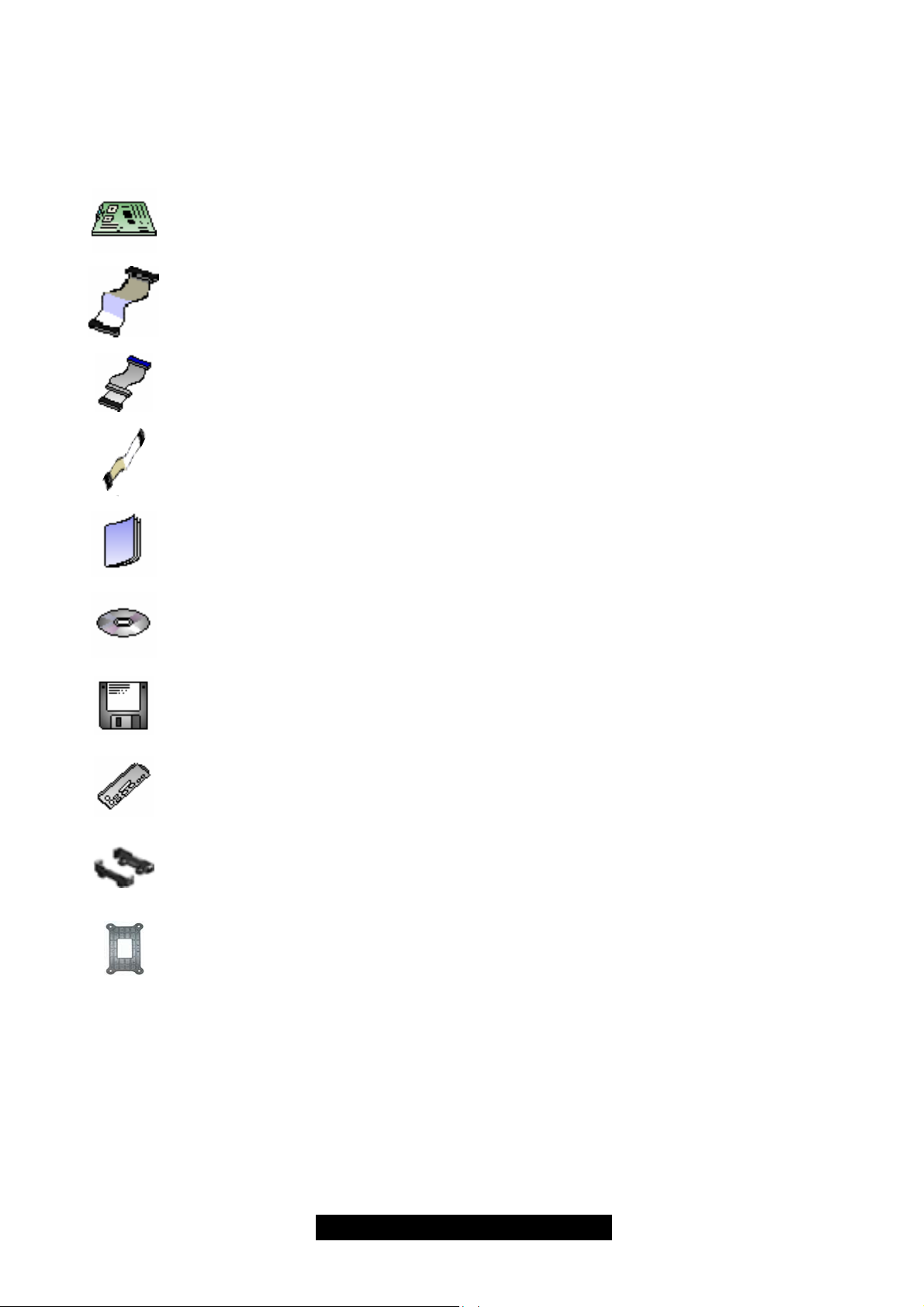
Check the box contents!
The retail motherboard package should contain the following:
1x Tiger i7505 motherboard
1x 34-Pin floppy drive cable
1x Ultra-DMA-100/66/33 IDE cable (2 for models with Promise SATA RAID)
2x Serial ATA cable (only for models with Promise SATA RAID)
1x Tiger i7505 User’s Manual
1x TYAN driver CD
2x Promise RAID driver diskette (only for models with Promise SATA RAID)
1x I/O shield
2X heatsink retention bracket kit
2X CPU reinforcement plate (packed with 9x screws)
If any of these items are missing, please contact your vendor/dealer for replacement before
continuing with the installation process.
3
http://www.TYAN.com

Chapter 1: Introduction
1.1 – Congratulations!
You are now the owner of one of the most advanced dual Intel Xeon processor solutions available:
the Tiger i7505. Based on Intel's E7505 chipset, the Tiger i7505 is Hyper-Threading ready utilizing onboard resources so that many data threads can be handled with ease by two
processors.
With a 8x/4x AGP slot, six USB 2.0 and 1.1 compatible ports, four Dual-channel DDR DIMM
sockets, a Gigabit Ethernet port, plus the 6-channel Audio and optional SATA RAID, the Tiger
i7505 S2668 is fast and flexible enough to fit your workstation needs.
Remember to visit TYAN’s Website at http://www.tyan.com
of TYAN’s products with FAQs, distributors list and BIOS setting explanations.
1.2 – Hardware Specifications
Processor
Dual mPGA604 ZIF sockets
Supports one or two Intel Xeon processors
with 512KB of integrated L2 cache
Onboard 4-phase VRM (VRM 9.1 spec)
Supports 400/533MHz Front-Side Bus
Chipset
Intel E7505 chipset
MCH + ICH4 + FWH
Winbond W83627HF Super I/O & systems
monitor controller
Memory
Four 184-pin 2.5-Volt DDR DIMM sockets
Dual channel memory bus
Supports ECC/non-ECC type unbuffered
memory modules
Supports PC1600/PC2100 DDR
(DDR200/DDR266)
Maximum 4GB
Expansion Slots
One 8x/4x mode AGP Pro50 slot
Five 32-bit 33MHz (5-Volt) PCI slots
Total of six usable slots
Integrated PCI IDE
Provides two PCI bus master channels for
up to four Enhanced IDE devices
Supports for UDMA 33/66/100 IDE drives
and ATAPI compliant devices
Supports up to four Enhanced IDE devices
Integrated Serial ATA RAID (Manufacturing
Option)
Promise PDC20378 SATA RAID controller
Supports 2 x SATA and 1 x Ultra ATA133
Supports RAID 0, 1, 0+1
Integrated LAN (Manufacturing Option)
Intel 82540EM Gigabit Ethernet (ANR), or
Intel 82551QM 10/100Mbit Ethernet (AN)
Integrated Audio
Intel ICH4 AC’97 compliant audio link
Realtek ALC65x 6-channel audio CODEC
Line-in, Line-out, Mic-in rear jacks
Front panel audio header
One 4-pin CD-ROM audio input header
One 4-pin Auxiliary header
BIOS
Phoenix BIOS 6.0 on 4Mbit Flash ROM
Supports Hyper-Threading technology
Supports BIOS Boot Specification v1.1 (BBS)
Supports ACPI
Supports SMBIOS v2.3
Support LAN remote boot (PXE)
Auto configuration of IDE hard disk types
Form Factor
ATX footprint (12" x 9.6")
ATX12V/EPS12V universal power suite
Stacked PS/2 keyboard and mouse ports
Two stacked two USB2.0/1.1 ports
Stacked two serial port and one parallel port
. There you can find information on all
channels
4
http://www.TYAN.com

Integrated I/O
PS/2 mouse and keyboard connector
Six USB 2.0 and 1.1 compatible ports
(4 rear connectors and 2 front panel headers
via an optional USB cable)
One floppy connector
Two 9-pin UART Serial connector
One 25-pin ECP/EPP/SPP parallel
connector
System Management
Total six 3-pin fan headers (three with
tachometer monitoring)
Temperature, voltage and fan monitoring
One RJ45 LAN port with LEDs
Audio Line-in, Line-out, and Mic-in ports
(Amplifier integrated)
Regulatory
FCC DoC (Declaration of Conformity)
European CE (Declaration of Conformity)
5
http://www.TYAN.com

Chapter 2: Board Installation
Installation
You are now ready to install your motherboard. The mounting hole pattern of the Tiger i7505
matches the ATX board specification. Before continuing with installation, confirm that your chassis
supports a standard ATX motherboard form factor.
How to install our products right….the first time!
The first thing you should do is read this user’s manual. It contains important information that will
make configuration and setup much easier. Here are some precautions you should take when
installing your motherboard:
(1) Ground yourself properly before removing your motherboard from the antistatic bag.
Unplug the power from your computer power supply and then touch a safely grounded
object to release static charge (i.e. power supply case). For the safest conditions, Tyan
recommends wearing a static safety wrist strap.
(2) Hold the motherboard by its edges. Do not touch the bottom of the board or flex the
board in any way.
(3) Avoid touching the motherboard components, IC chips, connectors, memory modules,
and leads.
(4) Place the motherboard on a grounded antistatic surface or on the antistatic bag that the
board was shipped in.
(5) Inspect the board for damage.
The following pages include details on how to install your motherboard into your chassis, as well
as installing the processor, memory, disk drives and cables.
NOTE DO NOT APPLY POWER TO THE BOARD IF IT HAS BEEN DAMAGED
WARNING:
The Tiger i7505 only supports EPS12V and ATX12V power supplies and will not operate
with other types. DO NOT use ATX 2.x and dual AMDGES power supplies as they will
damage the board and void your warranty.
Only ATX form factor chassis is supported. Other form factors may short the board
because the installation studs are in different locations.
6
http://www.TYAN.com
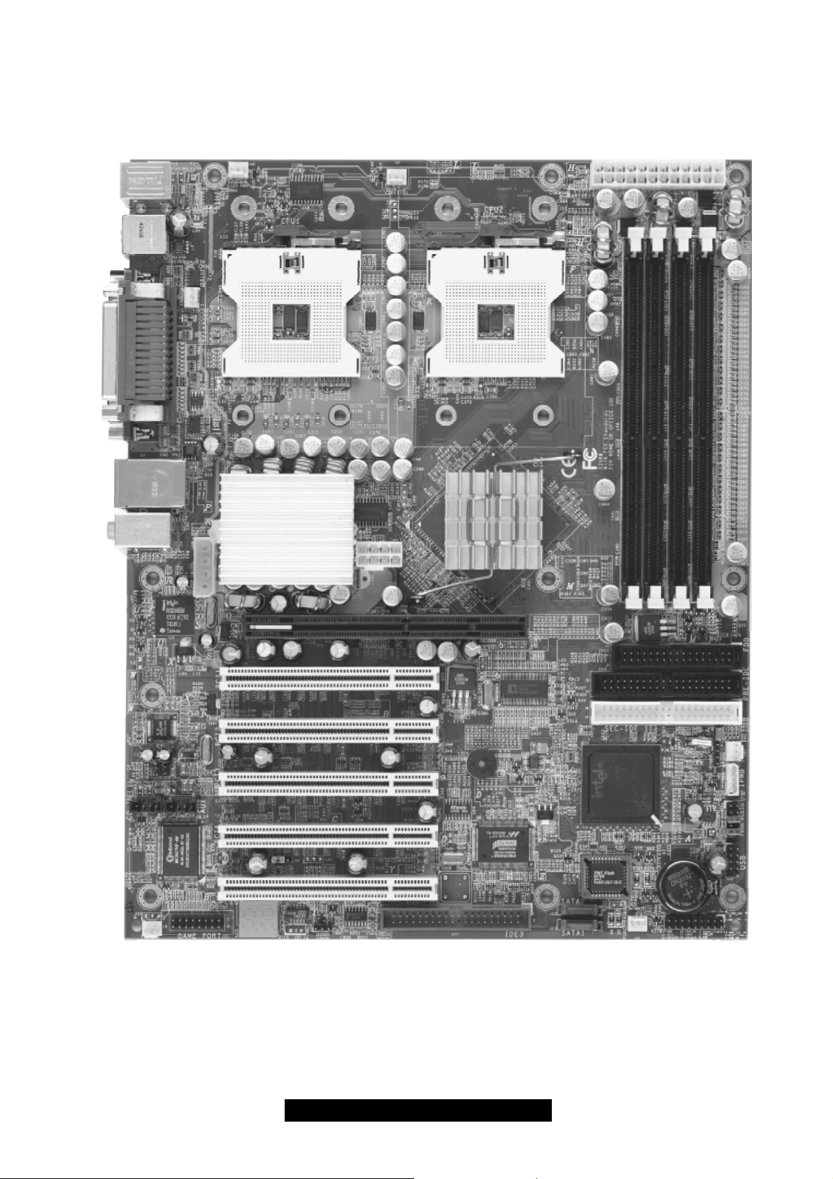
2.0 – Board Image
The following is an image of the Tiger i7505 S2668.
This picture is representative of the latest board revision available at the time of publishing.
The board you receive may or may not look exactly like the above picture.
The following page includes details on the vital components of this motherboard.
7
http://www.TYAN.com
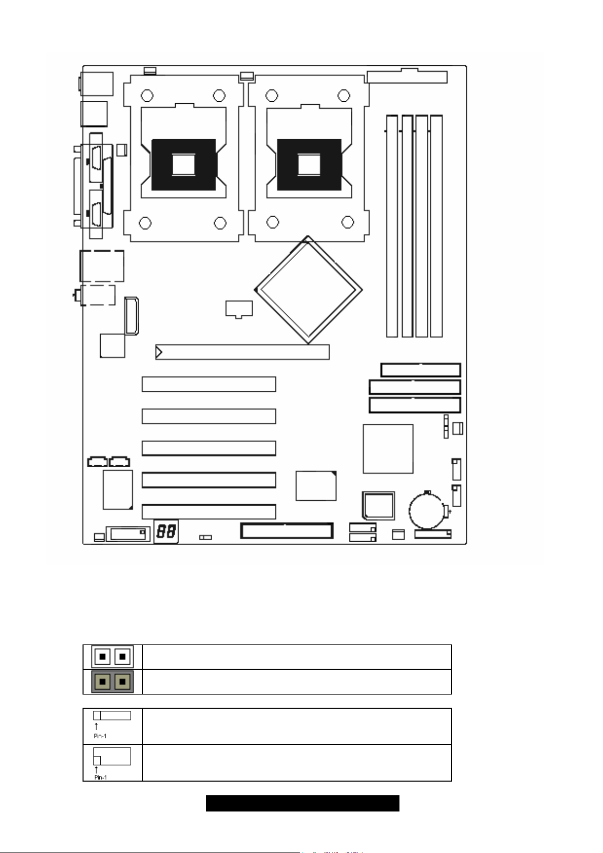
2.1 – Board Parts, Jumpers and Connectors
ppy
y
y
PS/2
USB
COM1 COM2
LPT
USB+RJ45
AUDIO
LAN
J23
PWR
J20
CPU2
J21
PWR
AGP PRO 8X/4X
CPU1
MCH
PWR
DIMM3
DIMM1
DIMM2
DIMM4
Flo
J2 J5
J43
PCI 32-bit / 33MHz (5V)
PCI 32-bit / 33MHz (5V)
PCI 32-bit / 33MHz (5V)
PCI 32-bit / 33MHz (5V)
I / O
SUPER
PCI 32-bit / 33MHz (5V)
J31
J33
IDE RAID
SATA
J12
J13
ICH4
BIOS
Primar
Secondar
J44
IDE
IDE
J36
J38
J37
J39
J40
J41
This diagram is representative of the latest board revision available at
the time of publishing. The board you receive may not look exactly like
the above diagram.
Jumper Legend
Jumper OFF without jumper cap
Jumper ON with jumper cap
Indicates where the location of pin-1
Indicates where the location of pin-1
8
http://www.TYAN.com
2.2 – Jumper and Connector Settings
Jumper /
Connector
Function Settings
J2 CD Audio Input Connector
J5 AUX Audio Input Connector
J12 Slave Serial ATA Connector
J13 Host Serial ATA Connector
J20
J21
J23
Fan Connector (for CPU2) With tachometer monitoring
Fan Connector (for CPU1) With tachometer monitoring
Fan Connector
J31 Game Port
J33
J36
J37
3-Pin Power LED Connector
Clear CMOS Jumper
Fan Connector
J38 Chassis Intrusion Connector
J39
J40
J41
J43
J44
Front Panel Audio Connector
Front Panel USB Connector
Front Panel System Connector
Fan Connector
Fan Connector With tachometer monitoring
* Refer to Page 11 for CMOS clearing procedures
Close Pin-1 and 2: Normal (Default)
Close Pin-2 and 3: Clear CMOS Mode*
9
http://www.TYAN.com
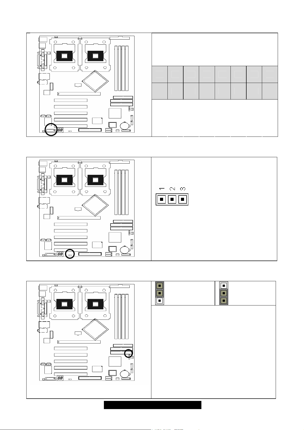
2.3 – CD Audio Connector (J2) and AUX Audio Connector (J5)
J 2 (CD Audio connector)
Connects to a CD-ROM drive via an optional
CD audio cable
J 5 (AUX Audio connector)
Connects to internal audio sources such as
TV tuner, MPEG, or other similar cards
2.4 – Slave/Host Serial ATA Connector (J12/J13) (on SATA RAID model only)
J12 (Slave Serial ATA connector)
J13 (Host Serial ATA connector)
Connects to the Serial ATA ready drives via
the Serial ATA cable
Along with the IDE RAID connector (see
page-8), these connectors support RAID 0,
RAID 1 or RAID 0+1 through the on board
SATA controller chip. You may use the RAID
feature to setup a disk array configuration or
to support additional drives
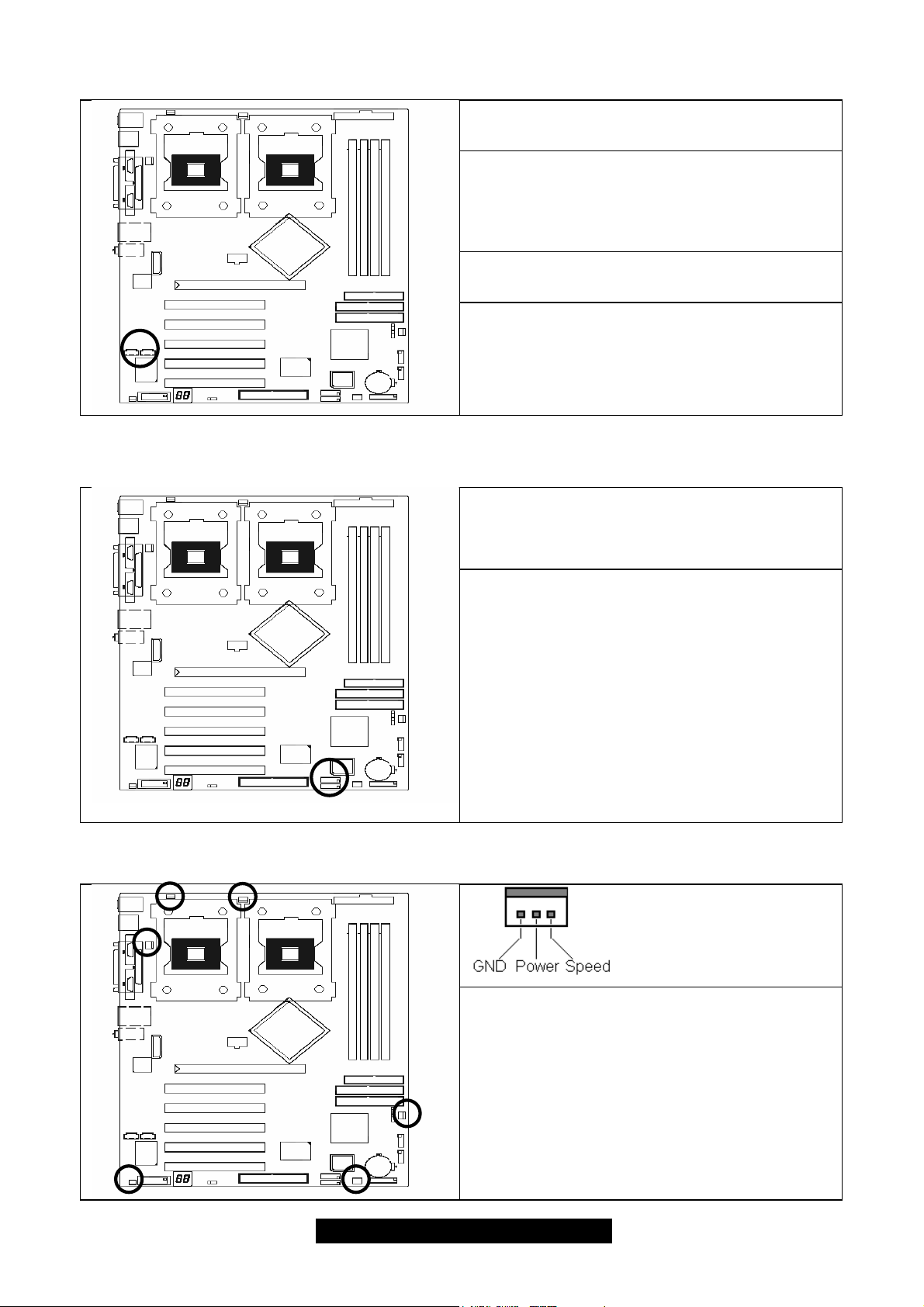
2.5 – Fan Connectors (J20, J21, J23, J37, J43 and J44)
Use these headers to connect chassis and
processor cooling fans to your motherboard.
Cooling fans can keep the system stable and
reliable for its product life.
Max 850mA fans supported
10
http://www.TYAN.com
(J23,J37,J43 w/o tachometer)
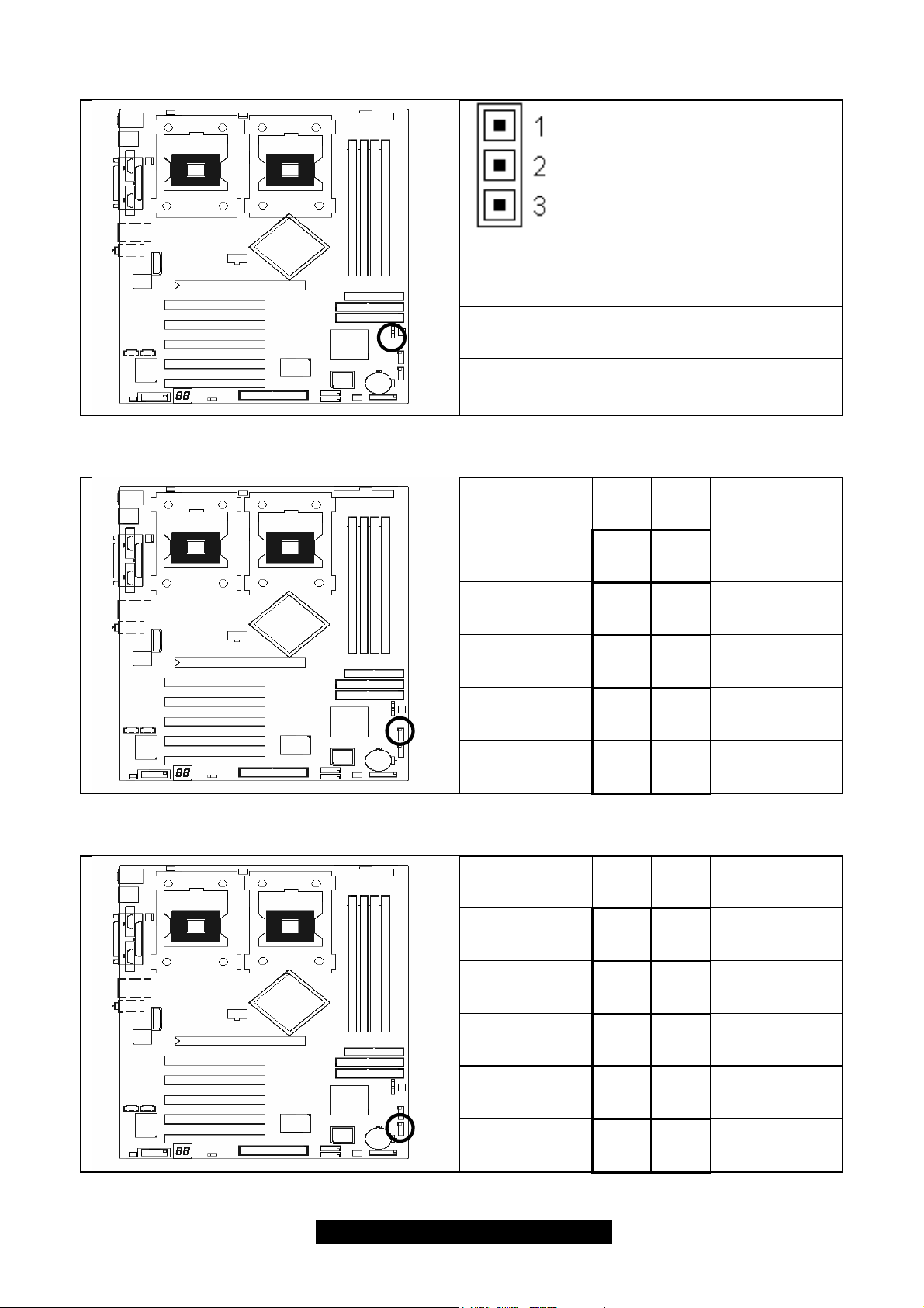
2.6 – GAME/MIDI Connector (J31)
VCC
15 13 11 9 7 5 3 1
16 14 12 10 8 6 4 2
NC
2.7 – Power LED Header (J33, for 3-pin connector)
This 3-pin header is to connect the system
power LED
J1B2
MIDI_IN
J1CY
J2B2
GND
J2CY
GND
MIDI_OUT
J1CX
J2CX
J1B1
J2B1
VCC
VCC
2.8 – Clear CMOS Jumper (J36)
Pin-1 Power LED+
Pin-2 NC
Pin-3 Power LED-
The LED lights up when the system power is
ON, and blinks when the system is in SLEEP
mode
1
Normal
(Default)
Use this jumper when you
forget your system/setup password
Need to clear system BIOS setting
How to clear the CMOS data
1. Power off system and disconnect power
supply from AC source
2. Use jumper cap to close Pin-2 and 3 for
several seconds to Clear CMOS
3. Replace jumper cap to close Pin-1 and 2
(default setting)
4. Reconnect power supply to AC source
5. Power on system
1
Clear
CMOS
11
http://www.TYAN.com
2.9 – Chassis Intrusion Connector (J38)
2.10 – Front Panel Audio Connector (J39)
Pin-1
Chassis cable detection (low asserted)
Pin-2
Intrusion detection (low asserted)
Pin-3
GND
Signal
Description
Pin # Pin
#
Signal
Description
2.11 – Front Panel USB Connector (J40)
MIC input 1 2 Analog GND
MIC power 3 4 Analog VCC
Right line
output
NC 7 Key
Left line
output
Signal
Description
VCC 1 2 VCC
Channel E
Data-
5 6
9 10
Pin # Pin
#
3 4
Right line
return
Left line
return
Signal
Description
Channel F
Data-
Channel E
Data+
GND 7 8 GND
Key 10
5 6
Channel F
Data+
Not
connected
12
http://www.TYAN.com
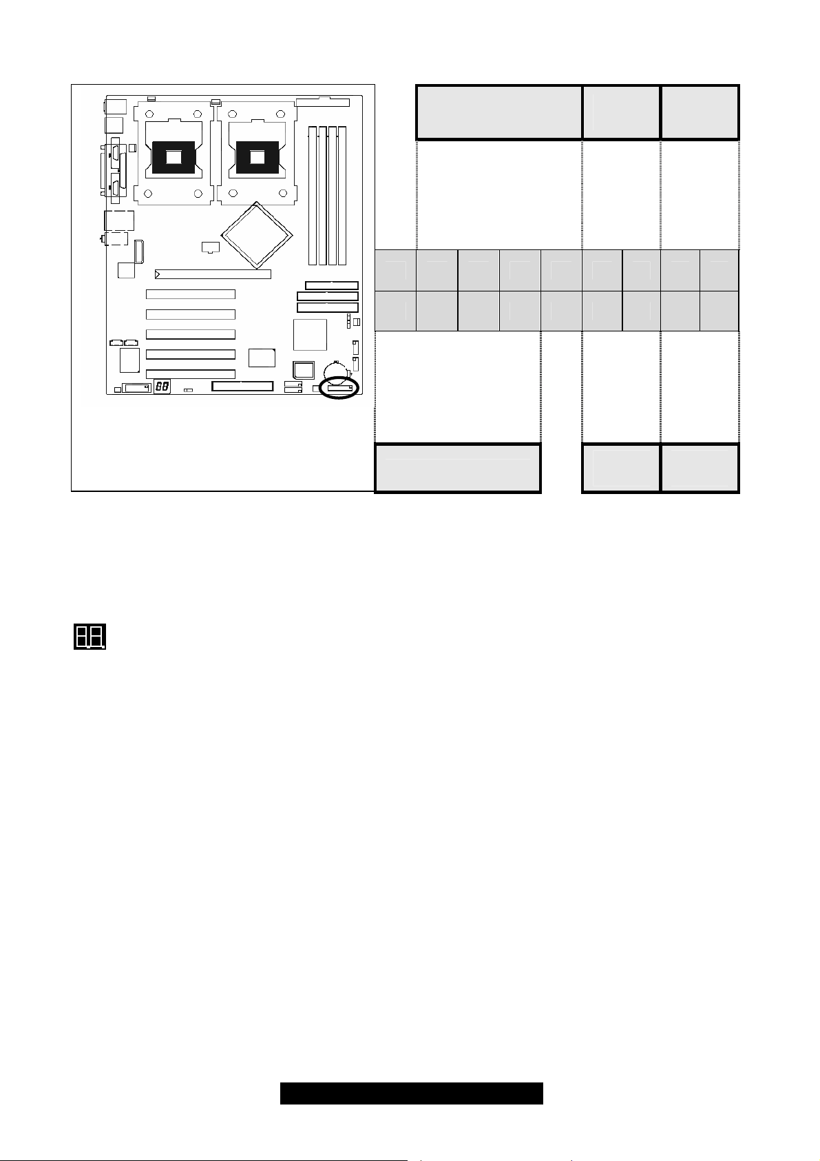
2.12 – Front Panel System Connector (J41)
Infrared Connector
Reset
Switch
HDD
LED
Reserved
HD LED—
RESET
IRTX
GND
IRRX
+5V
GND
17 15 13 11 9 7 5 3 1
18 16 14 12 10 8 6 4 2
SPEAKER
Speaker Connector
GND
GND
+5V
NC
GND
PWR
Power
Switch
PWR LED—
Power
LED
2.13 – OEM Reserved Connectors and Jumpers
Those connectors and jumpers which are not listed are reserved for OEM or factory use only.
2.14 – POST (Power-On-Self-Test) Code LED
HD LED+
PWR LED+
Refer to Appendix II for BIOS POST Code list
13
http://www.TYAN.com
2.15 – Mounting the Motherboard
Before installing your motherboard, make sure your chassis has the necessary motherboard
support studs installed. These studs are usually manufacturer pre-installed, metal and are gold in
color. If you are unsure of stud placement, lay the motherboard inside the chassis and align the
studs.
NOTE YOU MUST make sure that there are no studs where there are no screw holes.
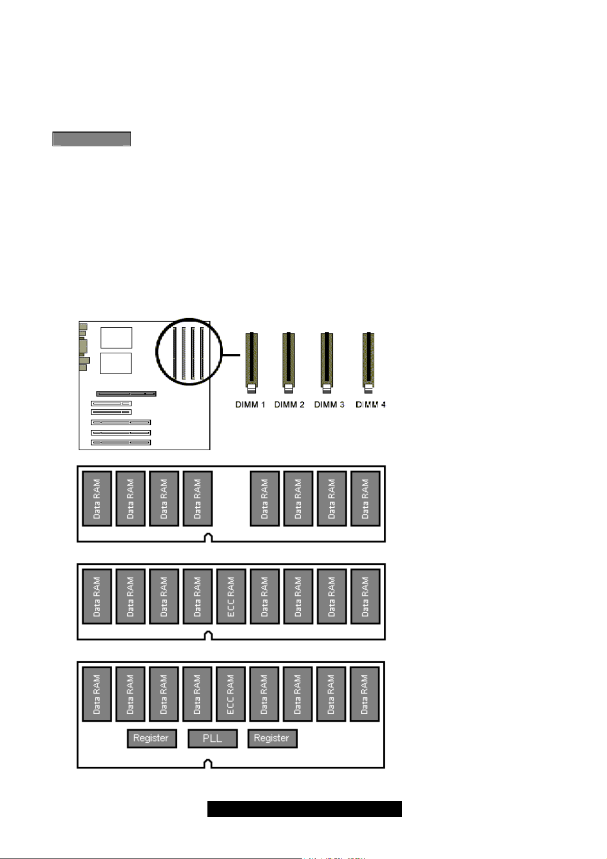
2.16 – Installing the Memory
Before attempting to install any memory, here are a few key points to note before installing
memory modules onto your board.
• Memory modules must be installed in pairs (DIMM1+DIMM2 or DIMM3+DIMM4)
• At least two unbuffered DDR ECC/non-ECC modules must be installed
• All installed memory will be automatically detected - no need to set any jumpers
• Supports 128MB, 256MB, 512MB and 1GB unbuffered DDR200/266 modules
• Supports up to 4GB of memory
DIMM1 + DIMM2
Or
DIMM3 + DIMM4
Or
DIMM1 + DIMM2 +
DIMM3 + DIMM4
DDR Unbuffered Non-ECC
√ supported
DDR Unbuffered ECC
√ supported
DDR Registered ECC
X unsupported
14
http://www.TYAN.com
Make sure that the memory you have is compatible with the motherboard as well as the
processor. For example, DDR200 and DDR266 memory modules can be used for
FSB=400MHz Intel Xeon processors but only DDR266 memory modules can be used
for FSB=533MHz Intel Xeon processors.
DDR200 (PC1600) DDR266 (PC2100)
Xeon FSB=400MHz
Xeon FSB=533MHz
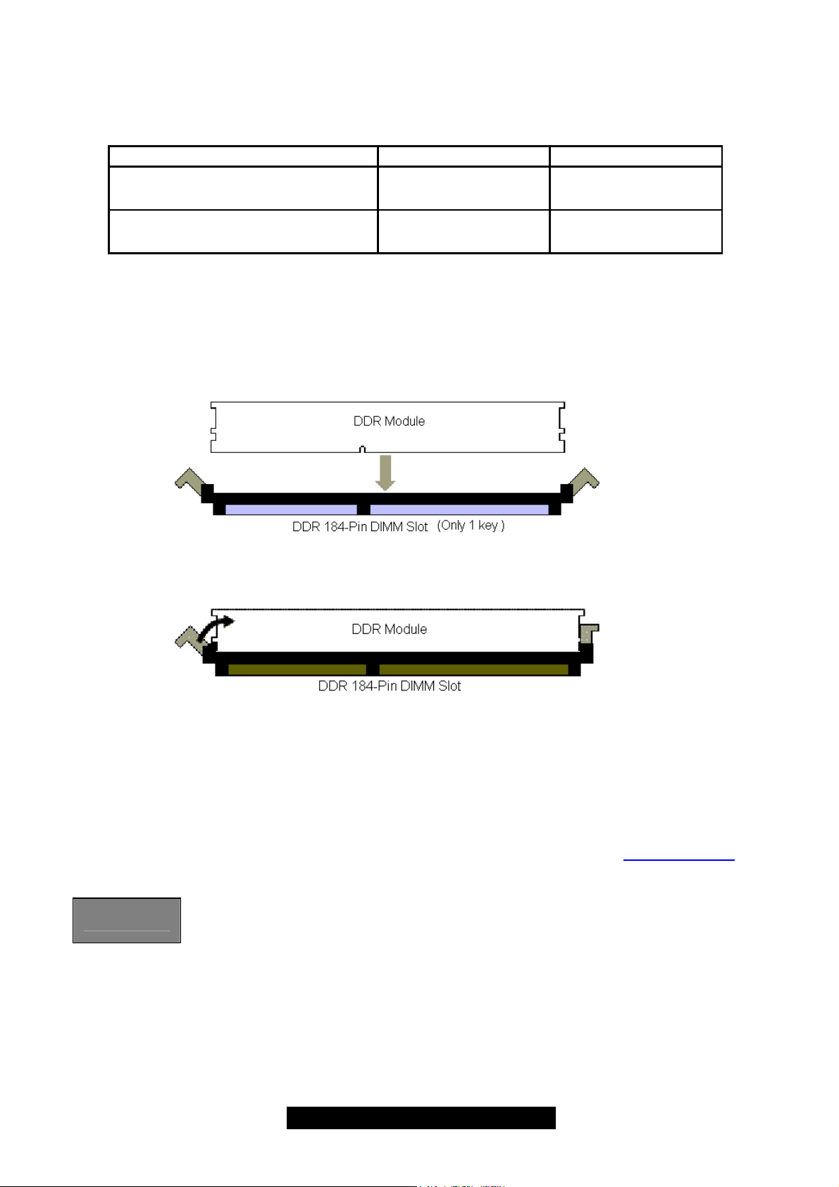
Memory Installation Procedure
When installing memory modules, make sure the modules align properly with the memory socket.
There should be a key (small indent) on your memory module that fits according to the key in the
memory socket. DDR modules and sockets have only one key, which is slightly off-center of the
module/socket. The method of installing memory modules is detailed in the following diagrams.
√
supported
X
unsupported
√
supported
√
supported
Once the memory modules are firmly seated in the socket, two clamps on either side will close
and secure the module into the socket. Sometimes you may need to close the clamps manually.
To remove the memory module, simply push the clamps outwards until the memory module pops
up. Then remove the module.
TIP: When installing memory, a module may require a considerable amount of force to seat
properly, although this is very rare. To avoid bending and damaging your motherboard, place it on
its anti-static bag and onto a flat surface, then proceed with memory installation.
For important memory information, please check Tyan’s web site at www.tyan.com
recommendations.
NOTE
YOU MUST unplug the power supply before performing system hardware
changes in order to avoid damaging the board or expansion device.
for
15
http://www.TYAN.com
2.17 – Installing the Processor(s) and Heatsink(s)
Your Tiger i7505 S2668 supports the latest processor technologies from Intel. Check the following
page on TYAN’s website http://www.tyan.com
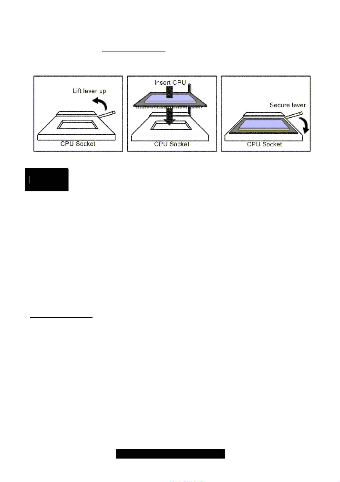
The following diagrams will detail how to install your processor(s):
Only identical CPUs can be used.
REMINDER
The processors you choose to use may not look exactly like the one pictured above, nor will the
socket look exactly the same. The diagram is a visual guide to help you install processors.
1. Lift the lever on the socket as far back as possible to the socket.
2. Align the processor with the socket. There are keys underneath the processor just like
3. Seat the processor firmly into the socket by gently pressing down until the processor
4. Place the socket lever back down until it snaps into place.
5. Your processor is installed.
6. Repeat these steps for the second processor if you are using two processors.
Take extra care when installing Xeon processors as they have fragile connector pins that
can bend and break if inserted improperly.
Heatsink Installation
After you are done installing the processor(s), you should proceed to installing their heatsink(s).
Heatsinks will ensure that the processors do not overheat and continue to operate at maximum
performance for as long as you own them. Overheated processors may damage the motherboard.
Because there are many different types of heatsinks available from many different manufacturers,
a lot of them have their own method of installation. For the safest method of installation and
information on choosing the appropriate heatsink, please refer to Intel’s website at
http://www.intel.com.
When installing only 1 processor, ensure to install it in CPU socket 1. (see page-8)
on memory modules to ensure that they insert the correct way.
sits flush with the socket.
for latest processor support:
16
http://www.TYAN.com
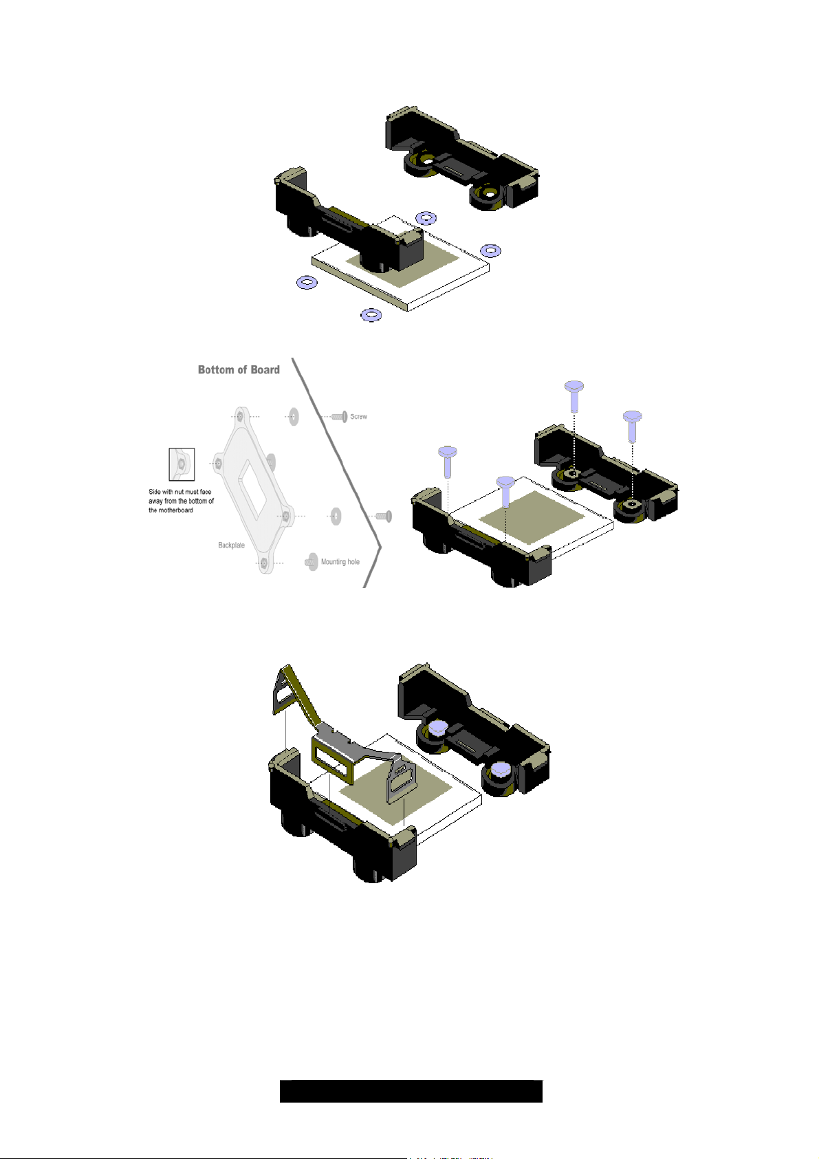
The following diagram will illustrate how to install the most common heatsinks:
a. Align the heatsink mounting bracket to the holes around the processor socket
b. (Remove the white nuts from the bracket if there is) Fasten the bracket with screw (packed
with the back plates) passing thru the motherboard, and mounting with the back plate firmly
c. Repeat process to mount all other brackets
d. Seat heatsink between brackets on the processor
e. Attach heatsink clips*
* The heatsink clips may vary with different mounting brackets
17
http://www.TYAN.com
 Loading...