

Page 1
82 Benning Street, West Lebanon, NH 03784 USA
(603) 298-5711 • www.thermal-dynamics.com
Manual 0-4797
SL80 Plasma Cutting
Hand Torch
Use with Lincoln
Installation and Operation Instructions
®
Pro-Cut® 80
General Information
Pro-Cut® 80
Torch Models
Cutting Capacity 85 Amps
Torc h Leads Lengt hs
Applications
Power Supply
Used W i t h:
Plasma Gas
Secondary Gas
Operating P ressure
Max. Input Pres sure 125 psi / 8.6 bar
Gas Flow (Cutting
and Gouging)
Duty Cycl e
Ambient
Tempera ture
Maximum Current 85 Amps
Volt age (V peak ) 500V
Arc Striking Voltage 7kV
Current Ratin g
Cooling
Catalog No. 7-5257
Ca talo g No. 7-5258
25' / 7.6 m
50' / 15.2 m
Shielded Drag Cutting
St andoff Cutting
®
Lincoln
Compress ed A i r (O nl y)
70 - 75 psi
4.8 - 5.2 bar
250 sc fh
(110 lpm)
100% @ 85 Am ps
@ 250 sc fh
104° F
40° C
Up to 85 Amps, DC,
Straight Polarity
Combinati on of Ambi ent
Air and Gas S tream
Through Torch
Pro-Cut 80
Refer to the Complete Assembly Replacement page for
configurations and catalog numbers.
These instructions are important for the proper installation
of the Torch. Read the instructions thoroughly before
attempting the installation. Keep these instructions for
reference.
Supplied Parts
The Replacement Torches include:
• Torch With Leads - 1 each
• Installation Instructions - 1 each
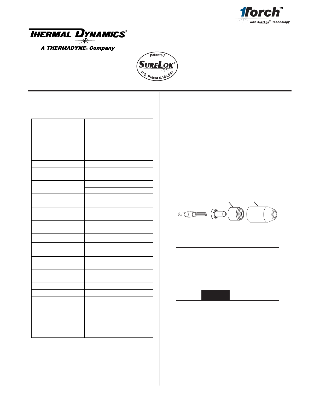
• Consumables (Installed on the Torch):
Art # A-04743
Electrode
Start Cartridge
Tip
Shield Cup
NOTE
The consumable parts installed in the Torch may
not necessarily be optimized for your Power Supply
or cutting application. For best results, refer to the
selection charts in this manual to choose the proper
consumables for your application.
CAUTION
The start cartridge supplied with this torch cannot
be used with any other 1Torch or on any other power
supply except Lincoln Pro-Cut 80.
Options
The following torch options are available. Refer to the
complete assembly replacement list for catalog numbers.
• Cutting Guide Kits
* Lincoln and Pro-Cut are registered trademarks of Lincoln
Electric.
©
2005,2006 by Thermal Dynamics Corp., Printed in USA.
• Leather Leads Covers
• Standoff Cutting Guide
Manual 0-4797 1 October 20, 2006 Rev. AA.01
Page 2
Torch Specifications
!
E. Torch Lead Pin Out
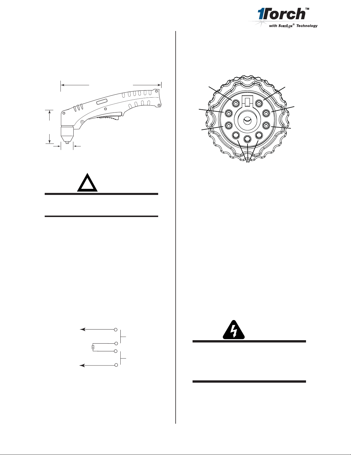
A. Torch Configuration and Dimensions
The torch head is at 75° to the torch handle. The torch
includes a torch handle and torch trigger assembly.
9.5" (241 mm)
3.75"
(95 mm)
1.17" (29 mm)
Art # A-03322
B. Operating Notes
WARNING
This torch is not to be used with oxygen (O2).
NOTE
Operating pressure varies with torch model,
operating amperage, and torch leads length. Refer
to gas pressure settings chart for each model.
This pin out is for the torch lead connector that attaches to the console. It indicates the placement of the
individual lead wires.
Red
Red
Green
9
8
7
6
1
4
5
Empty
White
2
3
Black
Orange
Art # A-07609
Connecting Torch
Torch leads connect directly to the power supply receptacle.
Align the leads connector with the power supply
receptacle. Press the connector into the receptacle fully.
Turn the connector locking ring to secure the connector to
the receptacle. Do not use the locking ring to pull the
connector into the receptacle.
C. Direct Contact Hazard
For exposed tip the recommended standoff is 1/8" - 1/4"
(3 - 6.4 mm).
D. Parts-In-Place (PIP) Circuit - 12 vdc
The torch and leads include circuitry called Parts-InPlace (PIP). This circuit includes a switch on the torch
head. The shield cup closes this switch when properly
installed. The torch will not operate if this switch is
open.
To Control
Torch Switch
Cable Wiring
PIP Switch
A-04791
Torch Trigger
Shield Cup
Spare Parts Label
Included with the torch is an adhesive label. Apply the
label to the power supply, where the operator can see it for
easy reference.
Torch Parts Selection
Refer to the Consumables Selection Chart for the various
torch parts for the application and operation.
WARNINGS
Disconnect primary power to the system before
disassembling the torch or torch leads.
DO NOT touch any internal torch parts while the
AC indicator light of the Power Supply is ON.
The shield cup (or shield cup body and shield cap or
deflector) holds the tip and start cartridge in place. Position
the torch with the shield cup facing upward to keep these
parts from falling out when the cup is removed.
Change the torch parts as follows:
October 20, 2006 Rev. AA.01 2 Manual 0-4797
Page 3
1. Unscrew and remove the shield cup from the torch
head.
Operating Gas Pressure
Set gas pressure at the power supply regulator according
to the following charts. These charts are a guide only;
adjust as necessary for best performance.
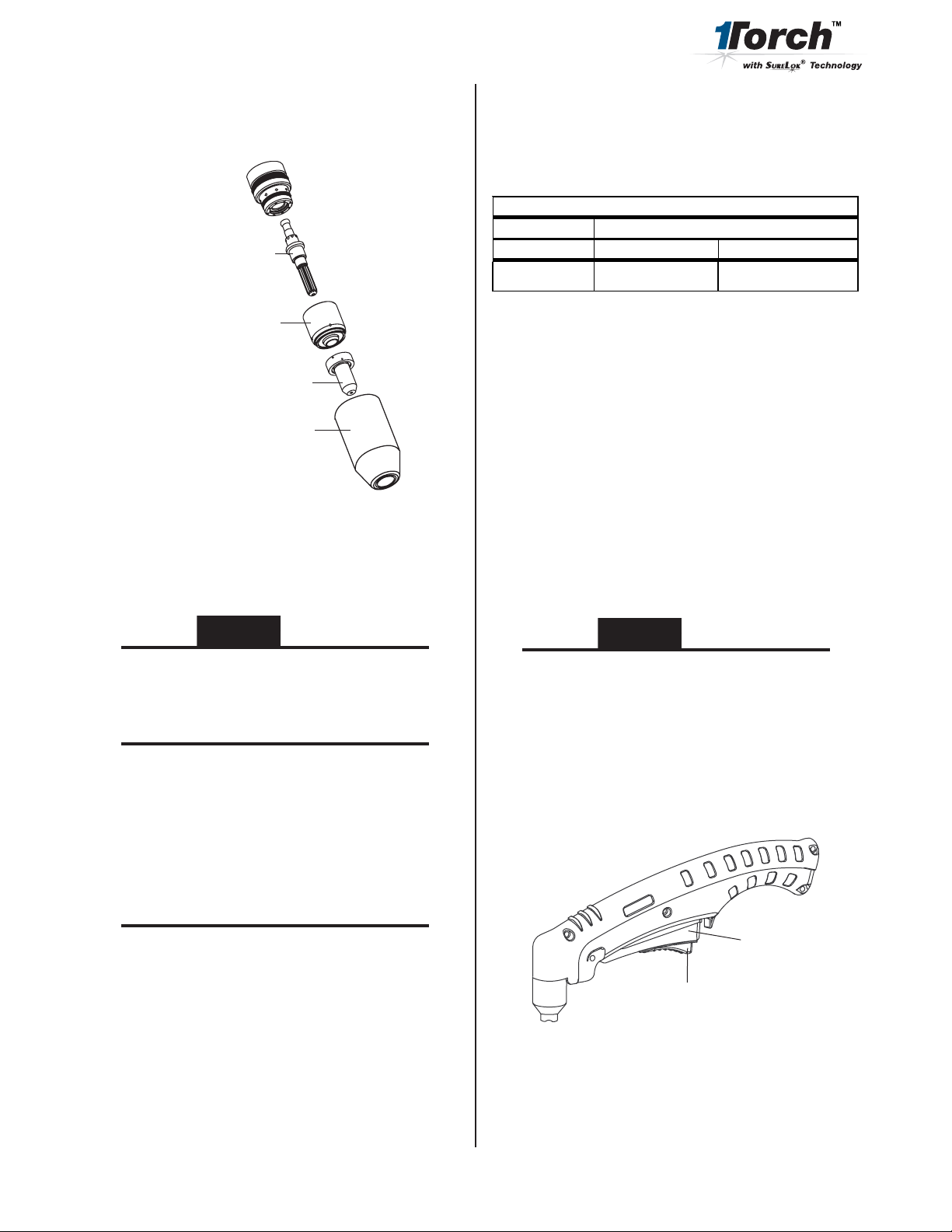
Torch Head
Electrode
Start Cartridge
Tip
Shield Cup
A-03645
2. Tilt the torch head to remove the tip and start cartridge.
3. Fit the desired start cartridge and tip onto the electrode.
CAUTION
Gas Pressure Settings
Leads Le ngth
Tip
80A 70 psi / 4. 8 bar 75 psi / 5. 2 bar
25' / 7.6 m 50' / 15.2 m
Cutting
The torch can be held comfortably in one hand or steadied
with two hands. Choose the holding technique that feels
most comfortable and allows good control and movement.
Sequence of Operation
1. Turn on power and adjust gas pressure on the Power
Supply pressure gauge. Refer to the charts for optimum
pressure settings for the combination of torch tip and
total lead lengths in use.
2. Adjust current output on the Power Supply to match
the selected tip and attach the work clamp firmly to the
work.
CAUTION
The start cartridge supplied with this torch cannot
be used with any other 1Torch or on any other power
supply except Pro-Cut 80.
NOTE
Refer to the consumables selection chart for the proper
combination of torch parts, including shield cups
and tips.
4. Hand tighten the shield cup until it is seated on the
torch head. Do not use tools to tighten the cup. If
resistance is felt when installing the cup, check the
threads before proceeding.
NOTE
When operating the torch in a normal condition, a
small amount of gas vents through the gap between
the shield cup and the torch handle. Do not attempt
to overtighten the shield cup as irreparable damage
to internal components may result.
Do not operate the torch with the torch tip in contact
with the work, as it will cause irreparable damage to
the torch parts.
3. Hold the torch away from your body.
4. Slide the trigger release toward the back of the torch
while simultaneously squeezing the trigger. The pilot
arc will start.
Trigger
Trigger Release
A-02986
5. Bring the torch within transfer distance to the work. The
main arc will transfer to the work, and the pilot arc will
shut off.
Manual 0-4797 3 October 20, 2006 Rev. AA.01
Page 4
NOTE
The gas preflow and postflow are a characteristic of
the power supply and not a function of the torch.
Common Operating Faults
The following are the more common cutting faults and the
possible causes:
Trigger
1
2
Trigger Release
3
4
Art # A-03383
6. Cut as usual. Simply release the trigger assembly to
stop cutting.
7. Follow normal recommended cutting practices as
provided in the power supply operator's manual.
A. Torch will not pilot or is erratic when torch switch is
activated
1. Input air setting improperly set. Input air pressure needs
to be adjusted for proper pilot.
a. If air pressure is too low, erratic or no pilot will
result. Increase air pressure to recommended
level.
b. If air pressure is too high, the pilot arc will stop
working after post flow cycle and the Safety
switch LED will light steady on the power
supply. Press the Safety switch button to reset
and decrease the air pressure to the recommend
level.
2. Wrong start cartridge installed.
a. The start Cartridge (9-8257) is specific to the
Pro-Cut 80. If any other start cartridge is
installed, the pilot arc will not start. Replace
with proper start cartridge, (9-8257).
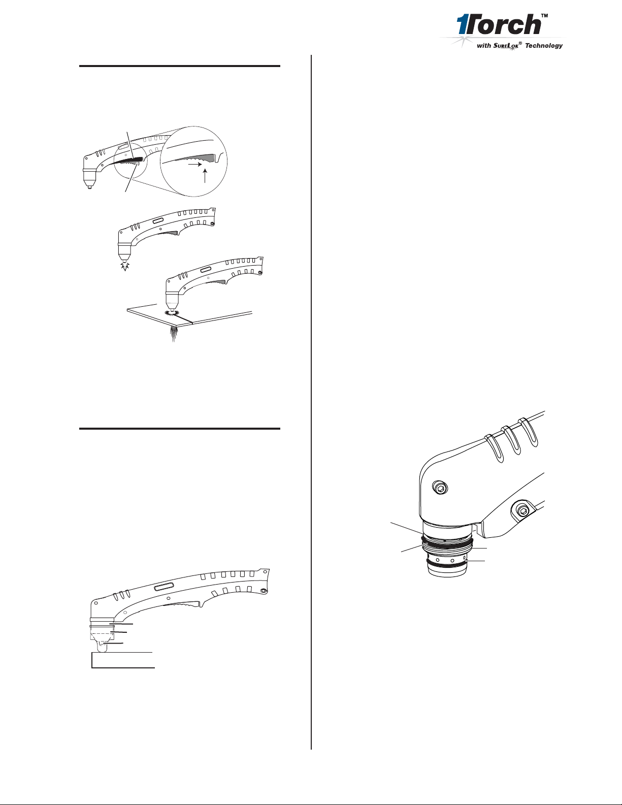
3. Upper O-ring on torch head is in wrong position
NOTE
When the shield cup is properly installed, there is a
slight gap between the shield cup and the torch
handle. Gas vents through this gap as part of normal
operation. Do not attempt to force the shield cup to
close this gap. Forcing the shield cup against the
torch head can damage components.
8. The optional Standoff Guide allows the user to easily
adjust and maintain a consistent standoff height for
most applications.
Shield Cup
Standoff Guide
Torch Tip
Workpiece
Art # A-04063
Art # A-03640
Upper Groove
with Vent Holes
Must Remain Open
Upper O-Ring
in Correct Groove
Threads
Lower O-Ring
October 20, 2006 Rev. AA.01 4 Manual 0-4797
Page 5

B. Difficult Starting Main Arc
1. Torch standoff too high from workpiece
Inspection and Replacement of
Consumable Torch Parts
2. Bad or no connection between work cable and workpiece
C. Main Arc Extinguishes
1. Cutting speed too slow
2. Torch standoff too high from workpiece
3. Bad or no connection between work cable and workpiece
4. Worn torch parts
D. Insufficient Penetration
1 Cutting speed too fast
2. Torch tilted too much
3. Metal too thick
4. Worn torch parts
5. Cutting current too low
E. Excessive Dross Formation
1. Cutting speed too slow
2. Torch standoff too high from workpiece
3. Worn torch parts
4. Improper cutting current
A. General Information
WARNINGS
Disconnect primary power to the system before
disassembling the torch or torch leads.
DO NOT touch any internal torch parts while the
AC indicator light of the Power Supply is ON.
Unthread the shield cup assembly to remove the
consumable torch parts.
1. Inspect the cup for damage. Wipe it clean or replace if
damaged. Slag built up on the shield cup that cannot
be removed may affect the performance of the system.
Torch Head
Electrode
F. Short Torch Parts Life
1. Oil or moisture in air source
2. Exceeding system capability (material too thick)
3. Cutting speed too fast
4. Excessive pilot arc time
5. Gas pressure too low
6. Improperly assembled torch
7. Torch tip contacting work piece at or above 40Amps
Start Cartridge
Tip
Shield Cup
A-03645
2. Check the tip for excessive wear (indicated by an
elongated or oversized orifice). Clean or replace the tip if
necessary.
Good Tip
Worn Tip
A-03406
Manual 0-4797 5 October 20, 2006 Rev. AA.01
Page 6

3. On torches with a shield cup body and a shield cap or
deflector, ensure that the cap or deflector is threaded
snugly against the shield cup body. In shielded drag
cutting operations (only), there may be an O-ring
between the shield cup body and drag shield cap. Do
not lubricate the O-ring.
Drag Shield Cap
6. Reinstall the Electrode by pushing it straight into the
torch head until it clicks.
WARNINGS
Refer to the consumables selection charts for the
proper combination of torch parts, including shield
cups and shield caps.
Shield
Cup Body
O-Ring No. 8-3488
Art # A-03878
4. Check the start cartridge for excessive wear, plugged
gas holes, discoloration, and for free movement of the
lower end plate. Replace if necessary.
Start Cartridge
Lower End Fitting
The use of any consumable parts other than
those specified by the Manufacturer may cause
irreparable damage to the torch head.
7. Reinstall the start cartridge and tip into the torch head.
Torch Head
Electrode
Start Cartridge
Tip
Shield Cup
Art # A-03621
CAUTION
The start cartridge supplied with this torch cannot
be used with any other 1Torch or on any other power
supply except Lincoln Pro-Cut 80.
5. Check the end of the electrode for excessive wear.
New Electrode
Art # A-03284
Worn Electrode
A-03645
8. Hand tighten the shield cup until it is seated on the
torch head. If resistance is felt when installing the cup,
check the threads before proceeding.
NOTE
When operating the torch in a normal condition, a
small amount of gas vents through the gap between
the shield cup and the torch handle. Do not attempt
to overtighten the shield cup as irreparable damage
to internal components may result.
October 20, 2006 Rev. AA.01 6 Manual 0-4797
Page 7

Torch Consumables
The illustration shows all consumable parts for this application.
Various front - end torch parts are available for different applications.
Use the single - piece shield cup for general purpose cutting operations with the torch tip in contact with the work (up
to 40 amps). This is the preferred method of cutting sheet metal up to 3/16" or 4.8 mm thick.
Also use the single - piece Shield Cup for 'standoff' cutting (with the torch tip 1/8" to 1/4" from the workpiece). This
is the preferred method for cutting metal thicker than 3/16" / 4.8 mm and at current levels above 40 amps. This
provides maximum visibility and accessibility.
Use the Shield Cup Body with the Deflector Shield Cap for improved resistance to reflected heat. This combination
provides cutting results similar to the single-piece Shield Cup, as well as easy change-over to gouging or drag shield
cutting.
Use the Shield Cup Body with the Drag Shield Cap for a consistent standoff distance with the drag shield in contact
with the workpiece. This is a simple and operator-friendly method of cutting between 50 and 100 amps.
The Standoff Guide fits both shield cup designs for this torch. The Guide allows the user to easily adjust and maintain
a consistent standoff height for most applications.
The start cartridge will not work for other applications.
Use only Genuine Thermal Dynamics consumables with this torch. The use of any other consumables may irreparably
damage the torch and/or void the warranty.
Electrode
9-8215
Art # A-05545
Start Cartridge
9-8257
DRAG SHIELD
CUTTING
Tip:
80A 9-8211
STANDOFF
CUTTING
Shield
Cup Body,
9-8237
Shield Cup
9-8218
O-Ring No. 8-3488
Shield Cap, Drag
70-100A 9-8236
Shield Cap, Deflector
9-8243
Standoff Guide
for All Applications
9-8422
Manual 0-4797 7 October 20, 2006 Rev. AA.01
Page 8

Replacement Hand Torch Parts
Item # Qty Description Catalog #
1 1 Torch Handle Replacement Kit (include items no. 2 & 3) 9-7030
2 1 Trigger Assembly Replacement Kit 9-7034
3 1 Handle Screw Kit (5 each, #6-32 x 1/2" cap screw, and wrench) 9-8062
4 1 Torch Head Assembly Replacement Kit (includes items No. 5 & 6) 9-8219
5 1 Large O-Ring 8-3487
6 1 Small O-Ring 8-3486
7 Leads Assembly with Lincoln Connectors (includes switch assemblies)
1 SL80 25' (7.6m) Leads Assembly 4-7865
includes valve assembly and Power Supply male connector
1 SL80 50' (15.2m) Leads Assembly 4-7866
includes valve assembly and Power Supply male connector
1
7
2
4
5
6
1
3
7
Art # A-04744
October 20, 2006 Rev. AA.01 8 Manual 0-4797
Page 9

Complete Assembly Replacement
Description Catalog #
Pro-Cut® 80
Options
Every effort has been made to provide complete and accurate information in this manual. However, the
publisher does not assume and hereby disclaims any liability to any party for any loss or damage caused by
errors or omissions in this Manual, whether such errors result from negligence, accident, or any other cause.
Hand Torches with Ergonomic Handle:
SL-80 Hand Torch 25 ft 7.6m 7-5257
SL-80 Hand Torch 50 ft 15.2m 7-5258
Leather Leads Cover, 25 foot / 7.6 m length 9-1270
Leather Leads Cover, 50 foot / 15.2 m length 9-1280
Straight Line Cutting Guide 7-8911
Radius / Roller Kit 7-7501
Circle Cutting Guide 7-3291
Deluxe Cutting Guide Kit 7-8910
Standoff Guide 9-8422
NOTE
Manual 0-4797 9 October 20, 2006 Rev. AA.01
Page 10

PATENT INFORMATION
The following parts are licensed under U.S. Patent No(s). 5120930 and 5132512
Catalog Number Description
9-8235 Shield Cap, Drag 50-60A
9-8236 Sheild Cap, Drag 70-100A
9-8237 Shield Cup, Body
9-8238 Shield Cap, Machine 50-60A
9-8239 Shield Cap, Machine 70-100A
9-8244 Shield Cap, Drag 40A
9-8245 Shield Cap, Machine 40A
October 20, 2006 Rev. AA.01 10 Manual 0-4797
Page 11

Statement of Warranty
LIMITED WARRANTY: Thermal Dynamics® Corporation (hereinafter “Thermal”) warrants that its products will be
free of defects in workmanship or material. Should any failure to conform to this warranty appear within the time
period applicable to the Thermal products as stated below, Thermal shall, upon notification thereof and substantiation
that the product has been stored, installed, operated, and maintained in accordance with Thermal’s specifications,
instructions, recommendations and recognized standard industry practice, and not subject to misuse, repair, neglect,
alteration, or accident, correct such defects by suitable repair or replacement, at Thermal’s sole option, of any components
or parts of the product determined by Thermal to be defective.
This warranty is exclusive and is in lieu of any warranty of merchantability or fitness for a particular purpose.
LIMITATION OF LIABILITY: Thermal shall not under any circumstances be liable for special or consequential
damages, such as, but not limited to, damage or loss of purchased or replacement goods, or claims of customers of
distributor (hereinafter “Purchaser”) for service interruption. The remedies of the Purchaser set forth herein are
exclusive and the liability of Thermal with respect to any contract, or anything done in connection therewith such as
the performance or breach thereof, or from the manufacture, sale, delivery, resale, or use of any goods covered by or
furnished by Thermal whether arising out of contract, negligence, strict tort, or under any warranty, or otherwise, shall
not, except as expressly provided herein, exceed the price of the goods upon which such liability is based.
This warranty becomes invalid if replacement parts or accessories are used which may impair the safety or
performance of any Thermal Product.
This warranty becomes invalid if the product is sold by non-authorized persons.
All SureLok™ RPT Torches have a one year Parts & Labor warranty
Warranty repairs or replacement claims under this limited warranty must be submitted by an authorized Thermal
Dynamics® repair facility within thirty (30) days of the repair. No transportation costs of any kind will be paid under
this warranty. Transportation charges to send products to an authorized warranty repair facility shall be the responsibility
of the customer. All returned goods shall be at the customer’s risk and expense.
Thermal Dynamics Corporation
82 Benning Street
West Lebanon, NH 03784 USA
Telephone: 603-298-5711
www.thermal-dynamics.com
Manual 0-4797 11 October 20, 2006 Rev. AA.01
 Loading...