

Page 1

100
100%
Duty
Cycle
PIP
H/F
LV
Start
Max
Input
125PSI
Op Pres
60-75
PSI
Max
Flow
400 scfh
60
SL60
SL100
PLASMA CUTTING TORCH
Model SL60, SL100 Hand
Torch
Model SL100 Machine Torch
Instruction Manual
Rev. AB Date: June 20, 2012 Manual # 0-2962
Operating Features:
Page 2

WE APPRECIATE YOUR BUSINESS!
Congratulations on your new Thermal Dynamics product. We are
proud to have you as our customer and will strive to provide you
with the best service and reliability in the industry. This product
is backed by our extensive warranty and world-wide service
network. To locate your nearest distributor or service agency
call 1-800-426-1888, or visit us on the web at www.thermal-
dynamics.com.
This Operating Manual has been designed to instruct you on the
correct use and operation of your Thermal Dynamics product.
Your satisfaction with this product and its safe operation is our
ultimate concern. Therefore please take the time to read the
entire manual, especially the Safety Precautions. They will help
you to avoid potential hazards that may exist when working with
this product.
YOU ARE IN GOOD COMPANY!
The Brand of Choice for Contractors and Fabricators Worldwide.
Thermal Dynamics is a Global Brand of manual and automation
Plasma Cutting Products for Thermadyne Industries Inc.
We distinguish ourselves from our competition through marketleading, dependable products that have stood the test of time.
We pride ourselves on technical innovation, competitive prices,
excellent delivery, superior customer service and technical support, together with excellence in sales and marketing expertise.
Above all, we are committed to developing technologically advanced products to achieve a safer working environment within
the welding industry.
Page 3

WARNINGS
Read and understand this entire Manual and your employer’s safety practices before installing,
operating, or servicing the equipment.
While the information contained in this Manual represents the Manufacturer's best judgement,
the Manufacturer assumes no liability for its use.
Plasma Cutting Torch
Model SL60 and SL100 Hand Torch
Model SL100 Machine Torch
Instruction Manual Number 0-2962
Protected under U.S. Patent Number 6,163,008. Other patents may apply.
Published by:
Thermal Dynamics Corporation
82 Benning Street
West Lebanon, New Hampshire, USA 03784
(603) 298-5711
www.thermal-dynamics.com
Copyright 2003, 2004, 2005, 2006, 2007 by
Thermal Dynamics Corporation
All rights reserved.
Reproduction of this work, in whole or in part, without written permission of the publisher is
prohibited.
The publisher does not assume and hereby disclaims any liability to any party for any loss or
damage caused by any error or omission in this Manual, whether such error results from negligence, accident, or any other cause.
Printed in the United States of America
Publication Date: September 29, 2005
Revision AB Date: June 20, 2012
Record the following information for Warranty purposes:
Where Purchased: ____________________________________
Purchase Date: ____________________________________
Power Supply Serial #: ____________________________________
Torch Serial #: ____________________________________
Page 4

TABLE OF CONTENTS
SECTION 1:
GENERAL INFORMATION ........................................................................... 1-1
1.01 Notes, Cautions and Warnings ........................................................................ 1-1
1.02 Important Safety Precautions ......................................................................... 1-1
1.03 Publications .................................................................................................... 1-2
1.04 Declaration of Conformity ............................................................................... 1-4
1.05 Statement of Warranty .................................................................................... 1-5
SECTION 2:
INTRODUCTION ..................................................................................... 2-1
2.01 Scope of Manual ............................................................................................. 2-1
2.02 General Description ........................................................................................ 2-1
2.03 Specifications ................................................................................................ 2-1
2.04 Options And Accessories ................................................................................ 2-3
2.05 Introduction to Plasma ................................................................................... 2-3
SECTION 3:
INSTALLATION ....................................................................................... 3-1
3.01 Introduction .................................................................................................... 3-1
3.02 Site Location ................................................................................................... 3-1
3.03 Unpacking ....................................................................................................... 3-1
3.04 Setting Up Hand Torch .................................................................................... 3-1
3.05 Setting Up Machine Torch ............................................................................... 3-1
3.06 Connecting Torch ............................................................................................ 3-2
3.07 Gas Connection ............................................................................................... 3-8
SECTION 4:
OPERATION ........................................................................................... 4-1
4.01 Introduction .................................................................................................... 4-1
4.02 Functional Overview ........................................................................................ 4-1
4.03 Getting Started ................................................................................................ 4-1
4.04 Torch Parts Selection ...................................................................................... 4-2
4.05 Cut Quality ...................................................................................................... 4-2
4.06 General Cutting Information ............................................................................ 4-3
4.07 Hand Torch Operation ..................................................................................... 4-4
4.08 Machine Torch Operation ................................................................................ 4-7
4.09 Recommended Cutting Speeds ....................................................................... 4-8
4.10 Gouging .......................................................................................................... 4-8
SECTION 5:
SERVICE ............................................................................................... 5-1
5.01 Introduction .................................................................................................... 5-1
5.02 General Torch Maintenance ............................................................................. 5-1
5.03 Common Operating Faults .............................................................................. 5-2
5.04 Inspection and Replacement of Consumable Torch Parts ............................... 5-3
5.05 Troubleshooting Guide .................................................................................... 5-4
Page 5

TABLE OF CONTENTS (continued)
SECTION 6:
PARTS LISTS ......................................................................................... 6-1
6.01 Introduction .................................................................................................... 6-1
6.02 Ordering Information ...................................................................................... 6-1
6.03 Replacement Parts for Hand Torch ................................................................ 6-2
6.04 Replacement Parts - for Machine Torches with Unshielded Leads .................. 6-4
6.05 Replacement Shielded Machine Torch Leads Assemblies .............................. 6-6
6.06 Hand Torch Consumables .............................................................................. 6-8
6.07 Hand Torch Spare Parts Kits ........................................................................... 6-8
6.08 Machine Torch Consumables ....................................................................... 6-10
6.09 Machine Torch Spare Parts Kits .................................................................... 6-10
6.10 Automated Torch Consumables .................................................................... 6-12
6.11 Automated Torch Spare Parts Kits ................................................................ 6-12
6.12 Complete Assembly Replacement ................................................................ 6-14
6.13 Options & Accessories .................................................................................. 6-15
PATENT INFORMATION ...................................................................................6-16
APPENDIX 1: TYPICAL SYSTEM SEQUENCE OF OPERATION BLOCK DIAGRAM .................. A-1
APPENDIX 2: GENERAL APPLICATION NOTES ......................................................... A-3
APPENDIX 3A: CUTMASTER 50 & CUTMASTER 51 SYSTEM DATA (HAND TORCH) ............. A-4
APPENDIX 3B: CUTMASTER 50 & CUTMASTER 51 SYSTEM DATA (MACHINE TORCH) ........ A-6
APPENDIX 4A: CUTMASTER 75 & CUTMASTER 81 SYSTEM DATA (HAND TORCH) ............. A-8
APPENDIX 4B: CUTMASTER 75 & CUTMASTER 81 SYSTEM DATA (MACHINE TORCH) .......A-10
APPENDIX 5: CUTMASTER 100 & 101 SYSTEM DATA (HAND and MACHINE TORCH) ..........A-12
APPENDIX 6: CUTMASTER 151 SYSTEM DATA (HAND and MACHINE TORCH) ..................A-14
APPENDIX 7A: PAKMASTER 50XL PLUS SYSTEM DATA (HAND TORCH) .........................A-16
APPENDIX 7B: PAKMASTER 50XL PLUS SYSTEM DATA (MACHINE TORCH) ....................A-18
APPENDIX 8A: PAKMASTER 75XL PLUS SYSTEM DATA (HAND TORCH) .........................A-20
APPENDIX 8B: PAKMASTER 75XL PLUS SYSTEM DATA (MACHINE TORCH) ....................A-22
APPENDIX 9: PAKMASTER 100XL PLUS SYSTEM DATA (MACHINE TORCH) ....................A-24
APPENDIX 10: HAND TORCH WIRING DIAGRAMS ...................................................A-26
Page 6

APPENDIX 11: MECHANIZED TORCH WIRING DIAGRAMS .........................................A-27
APPENDIX 12: AUTOMATED TORCH WIRING DIAGRAMS ..........................................A-28
APPENDIX 13: ATC ADAPTER PINOUT DIAGRAM ....................................................A-29
Rear Cover
Page 7
SECTION 1:
GENERAL INFORMATION
1.01 Notes, Cautions and Warnings
Throughout this manual, notes, cautions, and warnings are
used to highlight important information. These highlights
are categorized as follows:
NOTE
An operation, procedure, or background infor
mation which requires additional emphasis or
is helpful in efficient operation of the system.
-
GASES AND FUMES
Gases and fumes produced during the plasma cutting
process can be dangerous and hazardous to your health.
• Keepallfumesandgasesfromthebreathingarea.
Keep your head out of the welding fume plume.
• Use an air-supplied respirator if ventilation is not
adequate to remove all fumes and gases.
• Thekindsoffumesandgasesfromtheplasmaarc
depend on the kind of metal being used, coatings
on the metal, and the different processes. You must
be very careful when cutting or welding any metals
which may contain one or more of the following:
CAUTION
A procedure which, if not properly followed,
may cause damage to the equipment.
WARNING
A procedure which, if not properly followed,
may cause injury to the operator or others in
the operating area.
1.02 Important Safety Precautions
WARNINGS
OPERATION AND MAINTENANCE OF PLASMA
ARC EQUIPMENT CAN BE DANGEROUS AND
HAZARDOUS TO YOUR HEALTH.
Plasma arc cutting produces intense electric
and magnetic emissions that may interfere
with the proper function of cardiac pacemak
ers, hearing aids, or other electronic health
equipment. Persons who work near plasma arc
cutting applications should consult their medical health professional and the manufacturer of
the health equipment to determine whether a
hazard exists.
To prevent possible injury, read, understand
and follow all warnings, safety precautions and
instructions before using the equipment. Call
1-603-298-5711 or your local distributor if you
have any questions.
Antimony Chromium Mercury
Arsenic Cobalt Nickel
Barium Copper Selenium
Beryllium Lead Silver
Cadmium Manganese Vanadium
• AlwaysreadtheMaterialSafetyDataSheets(MSDS)
that should be supplied with the material you are
using. These MSDSs will give you the information
regarding the kind and amount of fumes and gases
that may be dangerous to your health.
• Forinformationonhowtotestforfumesandgases
in your workplace, refer to item 1 in Subsection 1.03,
Publications in this manual.
• Usespecialequipment,suchaswaterordowndraft
cutting tables, to capture fumes and gases.
• Donotusetheplasmatorchinanareawherecombustible or explosive gases or materials are located.
• Phosgene,atoxicgas,isgeneratedfromthevapors
of chlorinated solvents and cleansers. Remove all
sources of these vapors.
-
• Thisproduct, when used for welding or cutting,
produces fumes or gases which contain chemicals
known to the State of California to cause birth defects
and, in some cases, cancer. (California Health &
Safety Code Sec. 25249.5 et seq.)
ELECTRIC SHOCK
Electric Shock can injure or kill. The plasma arc process
uses and produces high voltage electrical energy. This
electric energy can cause severe or fatal shock to the
operator or others in the workplace.
Manual 0-2962 1-1 GENERAL INFORMATION
Page 8
• Nevertouchanypartsthatareelectrically“live”or
“hot.”
• Weardryglovesandclothing.Insulateyourselffrom
the work piece or other parts of the welding circuit.
• Repairorreplaceallwornordamagedparts.
• Extracaremustbetakenwhentheworkplaceismoist
or damp.
• Installand maintain equipmentaccording to NEC
code, refer to item 9 in Subsection 1.03, Publications.
• Disconnectpower source before performing any
service or repairs.
• ReadandfollowalltheinstructionsintheOperating
Manual.
FIRE AND EXPLOSION
• Forinformationonhowtotestfornoise,seeitem1
in Subsection 1.03, Publications, in this manual.
PLASMA ARC RAYS
Plasma Arc Rays can injure your eyes and burn your skin.
The plasma arc process produces very bright ultra violet
and infra red light. These arc rays will damage your eyes
and burn your skin if you are not properly protected.
• Toprotectyoureyes,alwayswearaweldinghelmet
or shield. Also always wear safety glasses with side
shields, goggles or other protective eye wear.
• Wearweldingglovesandsuitableclothingtoprotect
your skin from the arc rays and sparks.
• Keephelmetand safetyglassesingoodcondition.
Replace lenses when cracked, chipped or dirty.
Fire and explosion can be caused by hot slag, sparks, or
the plasma arc.
• Besurethereisnocombustibleorammablematerial in the workplace. Any material that cannot be
removed must be protected.
• Ventilateallammableorexplosivevaporsfromthe
workplace.
• Donotcutorweldoncontainersthatmayhaveheld
combustibles.
• Providearewatchwhenworkinginanareawhere
fire hazards may exist.
• Hydrogengas may be formed and trapped under
aluminum workpieces when they are cut underwater
or while using a water table. DO NOT cut aluminum
alloys underwater or on a water table unless the hydrogen gas can be eliminated or dissipated. Trapped
hydrogen gas that is ignited will cause an explosion.
NOISE
• Protectothersintheworkareafromthearcrays.
Use protective booths, screens or shields.
• Usetheshadeoflensassuggestedinthefollowing
per ANSI/ASC Z49.1:
Minimum Protective Suggested
Arc Current Shade No. Shade No.
Less Than 300* 8 9
300 - 400* 9 12
400 - 800* 10 14
* These values apply where the actual arc is
clearly seen. Experience has shown that lighter
filters may be used when the arc is hidden by
the workpiece.
Noise can cause permanent hearing loss. Plasma arc
processes can cause noise levels to exceed safe limits.
You must protect your ears from loud noise to prevent
permanent loss of hearing.
• Toprotectyourhearingfromloudnoise,wearprotective ear plugs and/or ear muffs. Protect others in
the workplace.
• Noiselevels should be measured to be sure the
decibels (sound) do not exceed safe levels.
GENERAL INFORMATION 1-2 Manual 0-2962
Page 9

1.03 Publications
Refer to the following standards or their latest revisions
for more information:
1. OSHA, SAFETY AND HEALTH STANDARDS, 29CFR 1910,
obtainable from the Superintendent of Documents, U.S. Government Printing Office, Washington, D.C. 20402
2. ANSI Standard Z49.1, SAFETY IN WELDING AND CUTTING,
obtainable from the American Welding Society, 550 N.W.
LeJeune Rd, Miami, FL 33126
3. NIOSH, SAFETY AND HEALTH IN ARC WELDING AND GAS
WELDING AND CUTTING, obtainable from the Superintendent
of Documents, U.S. Government Printing Office, Washington,
D.C. 20402
4. ANSI Standard Z87.1, SAFE PRACTICES FOR OCCUPATION
AND EDUCATIONAL EYE AND FACE PROTECTION, obtainable
from American National Standards Institute, 1430 Broadway,
New York, NY 10018
5. ANSI Standard Z41.1, STANDARD FOR MEN’S SAFETY-TOE
FOOTWEAR, obtainable from the American National Standards
Institute, 1430 Broadway, New York, NY 10018
6. ANSI Standard Z49.2, FIRE PREVENTION IN THE USE OF CUT-
TING AND WELDING PROCESSES, obtainable from American
National Standards Institute, 1430 Broadway, New York, NY
10018
14. American Welding Society Standard AWSF4.1, RECOMMENDED
SAFE PRACTICES FOR THE PREPARATION FOR WELDING AND
CUTTING OF CONTAINERS AND PIPING THAT HAVE HELD
HAZARDOUS SUBSTANCES, obtainable from the American
Welding Society, 550 N.W. LeJeune Rd, Miami, FL 33126
15. ANSI Standard Z88.2, PRACTICE FOR RESPIRATORY PROTECTION, obtainable from American National Standards Institute,
1430 Broadway, New York, NY 10018
7. AWS Standard A6.0, WELDING AND CUTTING CONTAINERS
WHICH HAVE HELD COMBUSTIBLES, obtainable from American Welding Society, 550 N.W. LeJeune Rd, Miami, FL 33126
8. NFPA Standard 51, OXYGEN-FUEL GAS SYSTEMS FOR WELDING, CUTTING AND ALLIED PROCESSES, obtainable from
the National Fire Protection Association, Batterymarch Park,
Quincy, MA 02269
9. NFPA Standard 70, NATIONAL ELECTRICAL CODE, obtainable
from the National Fire Protection Association, Batterymarch
Park, Quincy, MA 02269
10. NFPA Standard 51B, CUTTING AND WELDING PROCESSES,
obtainable from the National Fire Protection Association, Batterymarch Park, Quincy, MA 02269
11. CGA Pamphlet P-1, SAFE HANDLING OF COMPRESSED GASES
IN CYLINDERS, obtainable from the Compressed Gas Association, 1235 Jefferson Davis Highway, Suite 501, Arlington, VA
22202
12. CSA Standard W117.2, CODE FOR SAFETY IN WELDING AND
CUTTING, obtainable from the Canadian Standards Association,
Standards Sales, 178 Rexdale Boulevard, Rexdale, Ontario,
Canada M9W 1R3
13. NWSA booklet, WELDING SAFETY BIBLIOGRAPHY obtainable
from the National Welding Supply Association, 1900 Arch
Street, Philadelphia, PA 19103
Manual 0-2962 1-3 GENERAL INFORMATION
Page 10

1.04 Declaration of Conformity
Manufacturer: Thermal Dynamics Corporation
Address: 82 Benning Street
West Lebanon, New Hampshire 03784
USA
The equipment described in this manual conforms to all applicable aspects and regulations of the ‘Low Voltage Directive’
(European Council Directive 73/23/EEC as amended by Council Directive 93/68/EEC) and to the National legislation for the
enforcement of this Directive.
Serial numbers are unique with each individual piece of equipment and details description, parts used to manufacture a unit
and date of manufacture.
National Standard and Technical Specifications
The product is designed and manufactured to a number of standards and technical requirements. Among them are:
* CSA (Canadian Standards Association) standard C22.2 number 60 for Arc welding equipment.
*UL(UnderwritersLaboratory)rating94VOammabilitytestingforallprinted-circuitboardsused.
* ISO/IEC 60974-1 (BS 638-PT10) (EN 60 974-1) (EN50192) (EN50078) applicable to plasma cutting equipment and as-
sociated accessories.
* Extensive product design verification is conducted at the manufacturing facility as part of the routine design and manu-
facturing process. This is to ensure the product is safe, when used according to instructions in this manual and related
industry standards, and performs as specified. Rigorous testing is incorporated into the manufacturing process to ensure
the manufactured product meets or exceeds all design specifications.
Thermal Dynamics has been manufacturing products for more than 30 years, and will continue to achieve excellence in our
area of manufacture.
Manufacturers responsible representative: Steve Ward
victor Europe
Europa Building
Chorley N Industrial Park
Operations Director
Chorley, Lancashire,
England PR6 7BX
GENERAL INFORMATION 1-4 Manual 0-2962
Page 11

1.05 Statement of Warranty
LIMITED WARRANTY: Thermal Dynamics®Corporation(hereinafter“Thermal”)warrantsthatitsproductswillbefreeofdefectsinworkmanshipormaterial.
Should any failure to conform to this warranty appear within the time period applicable to the Thermal products as stated below, Thermal shall, upon
notification thereof and substantiation that the product has been stored, installed, operated, and maintained in accordance with Thermal’s specifications,
instructions, recommendations and recognized standard industry practice, and not subject to misuse, repair, neglect, alteration, or accident, correct such
defects by suitable repair or replacement, at Thermal’s sole option, of any components or parts of the product determined by Thermal to be defective.
THIS WARRANTY IS EXCLUSIVE AND IS IN LIEU OF ANY WARRANTY OF MERCHANTABILITY OR FITNESS FOR A PARTICULAR PURPOSE.
LIMITATION OF LIABILITY: Thermal shall not under any circumstances be liable for special or consequential damages, such as, but not limited to, damage
orlossofpurchasedorreplacementgoods,orclaimsofcustomersofdistributor(hereinafter“Purchaser”)forserviceinterruption.Theremediesofthe
Purchaser set forth herein are exclusive and the liability of Thermal with respect to any contract, or anything done in connection therewith such as the
performance or breach thereof, or from the manufacture, sale, delivery, resale, or use of any goods covered by or furnished by Thermal whether arising
out of contract, negligence, strict tort, or under any warranty, or otherwise, shall not, except as expressly provided herein, exceed the price of the goods
upon which such liability is based.
THIS WARRANTY BECOMES INVALID IF REPLACEMENT PARTS OR ACCESSORIES ARE USED WHICH MAY IMPAIR THE SAFETY OR PERFORMANCE
OF ANY THERMAL PRODUCT.
THIS WARRANTY IS INVALID IF THE PRODUCT IS SOLD BY NON-AUTHORIZED PERSONS.
The limited warranty periods for Thermal products shall be as follows (with the exception of XL Plus Series, CutMaster Series , Cougar and DRAG-GUN):
A maximum of three (3) years from date of sale to an authorized distributor and a maximum of two (2) years from date of sale by such distributor to the
Purchaser, and with the further limitations on such two (2) year period (see chart below).
The limited warranty period for XL Plus Series and CutMaster Series shall be as follows: A maximum of four (4) years from date of sale to an
authorized distributor and a maximum of three (3) years from date of sale by such distributor to the Purchaser, and with the further limitations on
such three (3) year period (see chart below).
The limited warranty period for Cougar and DRAG-GUN shall be as follows: A maximum of two (2) years from date of sale to an authorized
distributor and a maximum of one (1) year from date of sale by such distributor to the Purchaser, and with the further limitations on such two (2)
year period (see chart below).
Parts
XL Plus & Parts Parts
PAK Units, Power Supplies CutMaster Series Cougar/Drag-Gun All Others Labor
Main Power Magnetics 3 Years 1 Year 2 Years 1 Year
Original Main Power Rectifier 3 Years 1 Year 2 Years 1 Year
Control PC Board 3 Years 1 Year 2 Years 1 Year
All Other Circuits And Components Including, 1 Year 1 Year 1 Year 1 Year
But Not Limited To, Starting Circuit,
Contactors, Relays, Solenoids, Pumps,
Power Switching Semi-Conductors
Consoles, Control Equipment, Heat 1 Year 1 Year 1 Year
Exchanges, And Accessory Equipment
Torch And Leads
Maximizer 300 Torch 1 Year 1 Year
SureLok Torches 1 Year 1 Year 1 Year
All Other Torches 180 Days 180 Days 180 Days 180 Days
Repair/Replacement Parts 90 Days 90 Days 90 Days None
Warranty repairs or replacement claims under this limited warranty must be submitted by an authorized Thermal Dynamics® repair facility within thirty
(30) days of the repair. No transportation costs of any kind will be paid under this warranty. Transportation charges to send products to an authorized
warranty repair facility shall be the responsibility of the customer. All returned goods shall be at the customer’s risk and expense. This warranty
supersedes all previous Thermal warranties.
Effective August 6, 2001
Manual 0-2962 1-5 GENERAL INFORMATION
Page 12

Australia Terms of Warranty – 2012
Effective 1st January 2012, all warranties against defects (also known as a manufacturer’s warranty)
supplied with goods or services must comply with the new Australian consumer law regulations
(2010).
This Warranty Statement should be read in conjunction with the Warranty Schedule contained in the
operating instructions of the product. This schedule contains the warranty period applicable to the
product
Any claim under this warranty must be made within the warranty period which commences on the
date of purchase of the product. To make a claim under the warranty, take the product (with proof of
purchase from a Cigweld Accredited Seller) to the store where you purchased the product or contact
Cigweld Customer Care 1300 654 674 for advice on your nearest Service Provider.
All costs associated with lodging the warranty claim including the return of goods to Cigweld or our
Nominated Accredited Distributor/Accredited Service Provider are the responsibility of the consumer.
This warranty is given.
Cigweld Pty Ltd
A.B.N. 56007226815
71 Gower Street, Preston
Victoria, Australia, 3072
Phone: 1300 654 674
Email: enquiries@thermadyne.com.au
Website: www.cigweld.com.au
This warranty is provided in addition to other rights and remedies you have under law: Our goods
come with guarantees which cannot be excluded under the Australian Consumer Law. You are entitled to replacement or refund for a major failure and to compensation for other reasonably foreseeable loss or damage. You are also entitled to have the goods repaired or replaced if the goods fail to
be of acceptable quality and the failure does not amount to a major failure.
Failures due to incorrect use are not covered by this warranty and consumers are reminded to only
use the product in accordance with the Operating Instruction supplied with the product. Additional
copies of Operating Instructions are available from Cigweld Customer Care 1300 654 674 or the
Website.
GENERAL INFORMATION 1-6 Manual 0-2962
Page 13
SECTION 2:
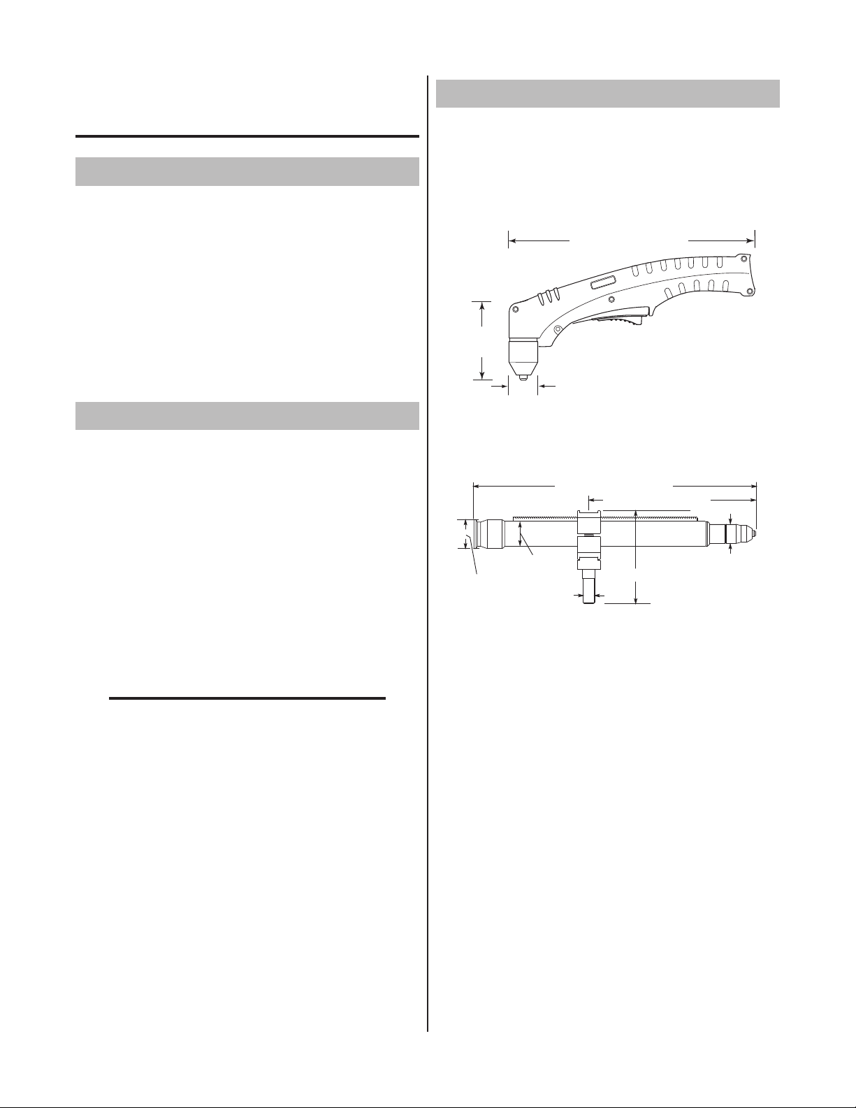
10.125" (257 mm)
3.75"
(95 mm)
1.17" (29 mm)
Art # A-03322_AB
Art # A-02998
1.75" /
44.5 mm
1.375" / 35 mm
15.875" / 403 mm
0.625" /
16 mm
4.95" / 126 mm
1.175" / 30 mm
9.285" / 236 mm
2.03 Specifications
INTRODUCTION
2.01 Scope of Manual
This manual contains descriptions, operating instructions
and maintenance procedures for the 1Torch Models SL60
and SL100 Plasma Cutting Torches. Service of this equipment is restricted to properly trained personnel; unqualified
personnel are strictly cautioned against attempting repairs
or adjustments not covered in this manual, at the risk of
voiding the Warranty.
Read this manual thoroughly. A complete understanding
of the characteristics and capabilities of this equipment will
assure the dependable operation for which it was designed.
2.02 General Description
Plasma torches are similar in design to the automotive
spark plug. They consist of negative and positive sections separated by a center insulator. Inside the torch, the
pilot arc starts in the gap between the negatively charged
electrode and the positively charged tip. Once the pilot arc
has ionized the plasma gas, the superheated column of
gasowsthroughthesmalloriceinthetorchtip,which
is focused on the metal to be cut.
A. Torch Configurations
1. Hand Torch, Models SL60 and SL100
The hand torch head is at 75° to the torch handle.
The hand torches include a torch handle and torch
trigger assembly.
2. Machine Torch, Model SL100
The standard machine torch has a positioning tube
with rack & pinch block assembly.
A single torch lead provides gas from a single source to be
usedasboththeplasmaandsecondarygas.Theairow
is divided inside the torch head. Single - gas operation
provides a smaller sized torch and inexpensive operation.
NOTE
Refer to Section 2.05, Introduction To Plasma,
for a more detailed description of plasma torch
operation.
Refer to the Appendix Pages for additional
specifications as related to the Power Supply
used.
B. Torch Leads Lengths
Hand Torches are available as follows:
• 20ft/6.1m,withO2BorATCconnectors
• 50ft/15.2m,withO2BorATCconnectors
Machine Torches are available as follows:
• 5foot/1.5m,withATCconnectors
• 10foot/3.05m,withATCconnectors
• 25foot/7.6m,withO2BorATCconnectors
• 50foot/15.2m,withO2BorATCconnectors
C. Torch Parts
Starter Cartridge, Electrode, Tip, Shield Cup
D. Parts - In - Place (PIP)
Torch Head has built - in switch
12 vdc circuit rating
Manual 0-2962 2-1 INTRODUCTION
Page 14
E. Type Cooling
p
s
!
SL60 and SL100 Torch Gas Specification
s
!
Combination of ambient air and gas stream through
torch.
F. Torch Ratings
SL60 Torch Ratin
Ambient
Temperature
Duty Cycle
Maximum Current
Voltage (V
Arc Striking Voltage
Ambient
erature
Tem
Duty Cycle
Maximum Current
Voltage (V
Arc Striking Voltage
)
peak
SL100 Torch Ratin
)
peak
100% @ 60 Amps @ 400 scfh
100% @ 100 Amps @ 400 scfh
gs
104° F
40° C
60 Amps
500V
7kV
gs
104° F
40° C
100 Amps
500V
7kV
G. Current Ratings
Current Rating
SL60 Torch & Leads
SL100 Torch & Leads
Up to 60 Amps, DC,
Straight Polarity
Up to 100 Amps, DC,
Straight Polarity
H. Gas Requirements
Gas (Plasma and Secondary) Compressed Air
Operating Pressure
Refer to NOTE
Maximum Input Pressure
Gas Flow (Cutting and Gouging)
WARNING
60 - 75 psi
4.1 - 5.2 bar
125 psi / 8.6
bar
300 - 500 scfh
142 - 235 lpm
This torch is not to be used with oxygen (O2).
NOTE
Operating pressure varies with torch model,
operating amperage, and torch leads length.
Refer to gas pressure settings charts for each
model.
I. Direct Contact Hazard
For exposed tip the recommended standoff is 3/16
inches / 4.7 mm.
J. Plasma Power Supply Used With
WARNING
Maximum current is 60 Amps for SL60 Torches,
or 100 Amps for SL100 Torches. Operation of
this torch at higher outputs may damage the
torch, the leads, the components, or the Power
Supply. DO NOT operate the SL60 torch at
more than 60 Amps, or the SL100 at more
than 100 Amps.
NOTE
Power Supply characteristics will determine
material thickness range.
• CutMaster50
• CutMaster51
• CutMaster75
• CutMaster81
• CutMaster100
• CutMaster101
• CutMaster151
• PakMaster50XLPlus
• PakMaster75XLPlus
• PakMaster100XLPlus
NOTE
Refer to the Appendix Pages for additional
specifications as related to the Power Supply
used.
INTRODUCTION 2-2 Manual 0-2962
Page 15
2.04 Options And Accessories
A-00002
Workpiece
Power
Supply
+
_
C
B
A
2.05 Introduction to Plasma
These items can adapt a standard system to a particular
application or further enhance performance (refer to Section 6 for ordering information).
• SparePartsKits-Variouskitscontainingreplacement
consumable torch parts.
• DeluxeCuttingGuideKit-Easyadd-onattachments
for precise straight line, circle cutting, and beveling.
Includes carrying case.
• TriggerGuardKits(forhandtorches)-Theseoffer
additional protection from accidental activation of
the torch switch.
• 1-3/8"MountingTube(formachinetorches)
• PinionAssembly(formachinetorches)
• ComputerControl(CNC)Cable25Ft/7.6mor50
Ft / 15.2 m (for machine torches)
• RemotePendant Control Assembly - for machine
torch applications. Hand Pendant Control has 20 ft.
(6.1 m) cable which provides ON & OFF signals to
the Power Supply.
• ExtensionCableforHandPendantControl-25ft/7.6
m cable which can be added to the Hand Pendant
Control cable to provide a total control cable length
of 50 ft / 15.2 m.
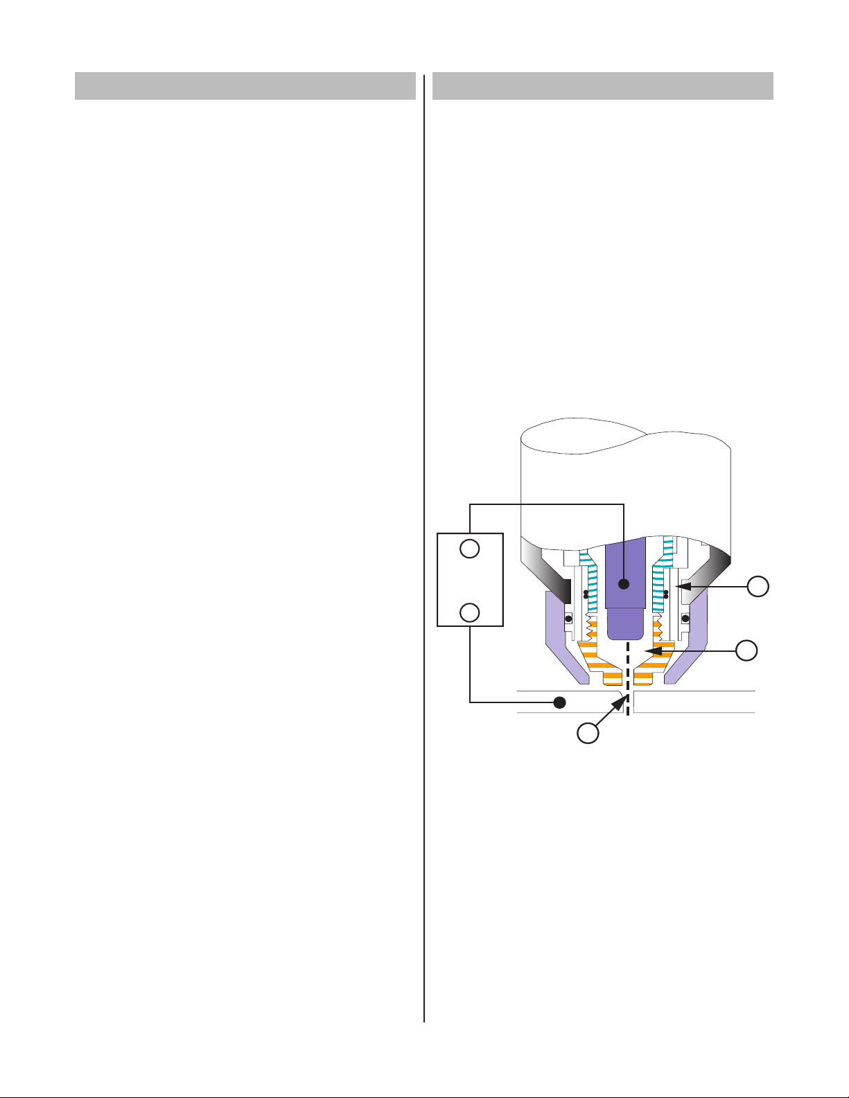
A. Plasma Gas Flow
Plasma is a gas which has been heated to an extremely
high temperature and ionized so that it becomes electrically conductive. The plasma arc cutting and gouging processes use this plasma to transfer an electrical
arc to the workpiece. The metal to be cut or removed
is melted by the heat of the arc and then blown away.
While the goal of plasma arc cutting is separation of
the material, plasma arc gouging is used to remove
metals to a controlled depth and width.
In a Plasma Cutting Torch a cool gas enters Zone B,
where a pilot arc between the electrode and the torch
tip heats and ionizes the gas. The main cutting arc
then transfers to the workpiece through the column
of plasma gas in Zone C.
• LeadsExtensionsfortorcheswithATCconnectors
• LeatherLeadsCovers
Typical Torch Head Detail
By forcing the plasma gas and electric arc through a
small orifice, the torch delivers a high concentration
of heat to a small area. The stiff, constricted plasma
arc is shown in Zone C. Direct current (DC) straight
polarity is used for plasma cutting, as shown in the
illustration.
Zone A channels a secondary gas that cools the torch.
This gas also assists the high velocity plasma gas in
blowing the molten metal out of the cut allowing for a
fast, slag - free cut.
Manual 0-2962 2-3 INTRODUCTION
Page 16
B. Gas Distribution
A-02997
Torch Trigger
PIP Switch
Shield Cup
To Control
Cable Wiring
Torch Switch
A-03504
PIP Switch
Shield Cup
To Control
Cable Wiring
The single gas used is internally split into plasma and
secondary gases.
The plasma gas ows into the torch through the
negative lead, through the starter cartridge, around
the electrode, and out through the tip orifice.
Thesecondarygasowsdownaroundtheoutsideof
the torch starter cartridge, and out between the tip and
shield cup around the plasma arc.
C. Pilot Arc
When the torch is started a pilot arc is established
between the electrode and cutting tip. This pilot arc
creates a path for the main arc to transfer to the work.
D. Capacitive Discharge
Because direct current (DC) alone is not sufficient to
strike and maintain the pilot arc, capacitive discharge
is also used. The high voltage jumps between the tip
and electrode with the DC following.
NOTE
Not all power supplies have this feature.
E. Main Cutting Arc
DC power is also used for the main cutting arc. The
negative output is connected to the torch electrode
through the torch lead. The positive output is connected to the workpiece via the work cable and to the
torch through a pilot wire.
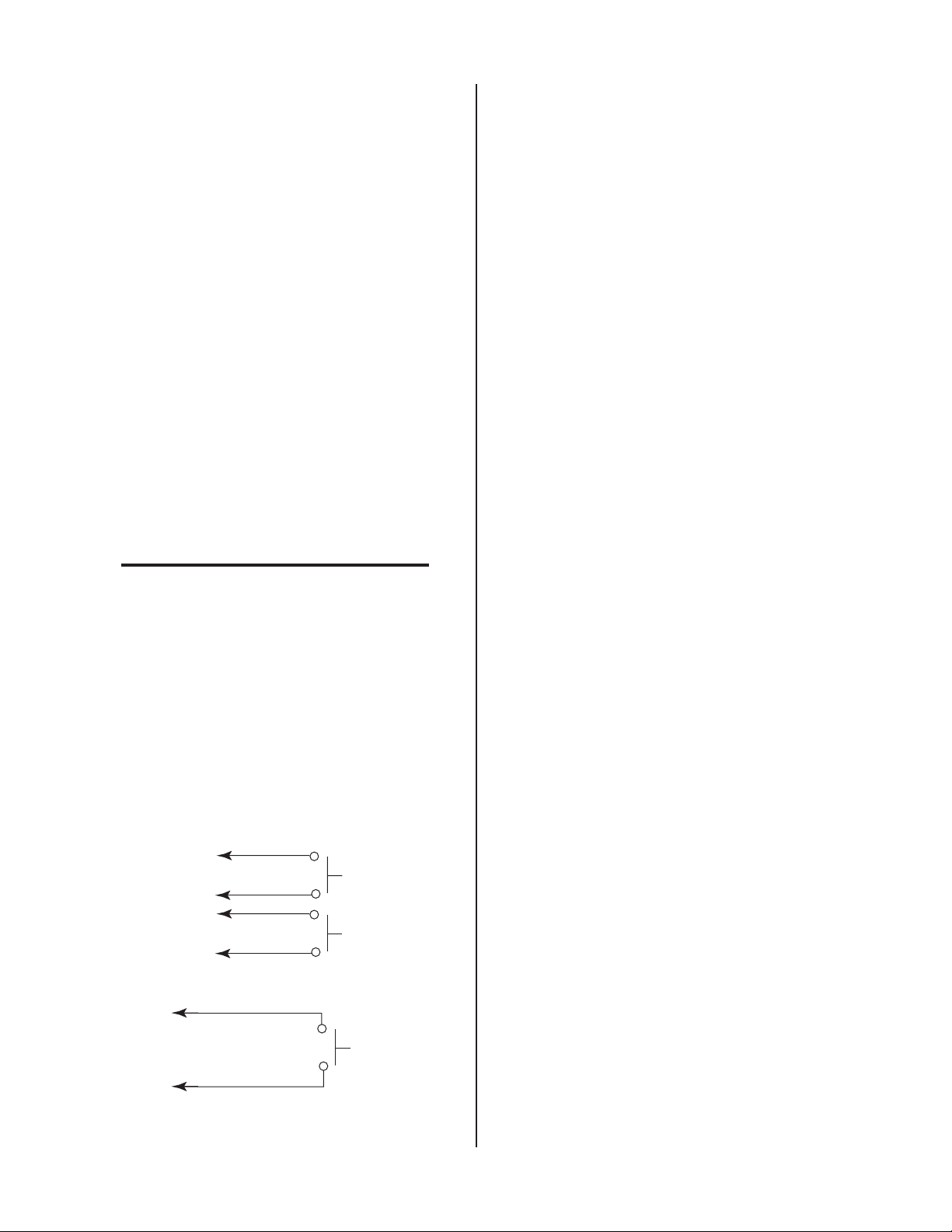
F. Parts - In - Place (PIP)
The torch includes a 'Parts - In - Place' (PIP) circuit.
When the shield cup is properly installed, it closes a
switch. The torch will not operate if this switch is open.
Parts - In - Place Circuit Diagram for Hand Torch
Parts - In - Place Circuit Diagram for Machine Torch
INTRODUCTION 2-4 Manual 0-2962
Page 17
SECTION 3:
A-02585
Workpiece
Square
Pinch Block
Assembly
INSTALLATION
3.01 Introduction
This section describes installation of the Torch. These
instructions apply to the Torch and Leads Assemblies only;
installation procedures for the Power Supply, Options and
Accessories are given in Manuals specifically provided for
those parts.
The complete installation consists of:
• SiteSelection
• Unpacking
• SettingUpTorch
• ConnectingTorch
• GasConnection
3.02 Site Location
Select a clean, dry location with good ventilation and adequate working space around all components.
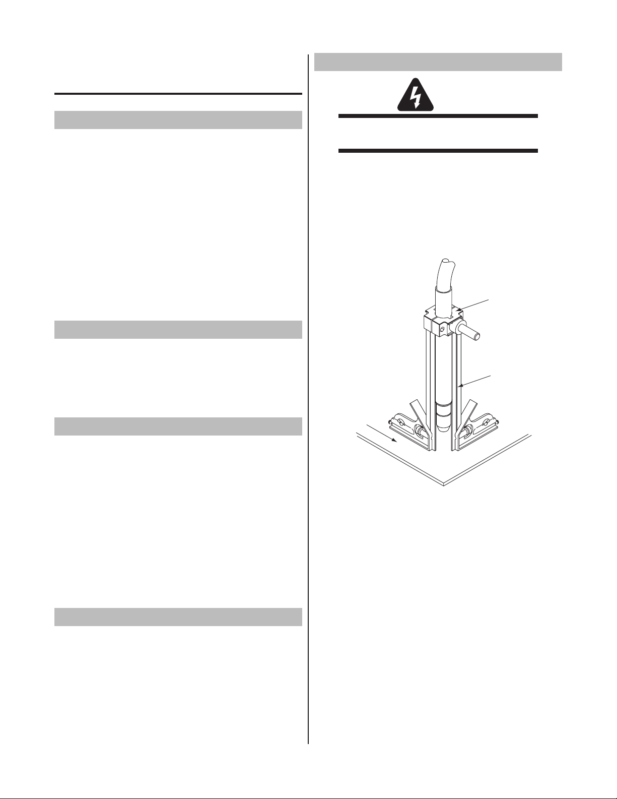
3.05 Setting Up Machine Torch
WARNING
Disconnect primary power at the source before
disassembling the torch or torch leads.
The machine torch includes a positioning tube with rack
and pinch block assembly.
1. Mount the torch assembly on the cutting table.
2. To obtain a clean vertical cut, use a square to
align the torch perpendicular to the surface of the
workpiece.
Review the safety precautions in the front of this manual
to be sure that the location meets all safety requirements.
3.03 Unpacking
Each component of the system is packaged and protected
with a carton and packing material to prevent damage
during shipping.
1. Unpack each item and remove all packing material.
2. Locate the packing list and use the list to identify and
account for each item.
3. Inspect each item for possible shipping damage. If
damage is evident, contact your distributor and / or
shipping company before proceeding with system
installation.
3.04 Setting Up Hand Torch
The hand torch requires no special set up. The proper torch
parts (shield cup, tip, starter cartridge, and electrode) must
be installed for the type of operation. Refer to Section 4.04,
Torch Parts Selection for details.
Machine Torch Set - Up
3. The proper torch parts (shield cup, tip, starter
cartridge, and electrode) must be installed for the
type of operation. Refer to Section 4.04, Torch
Parts Selection for details.
Manual 0-2962 3-1 INSTALLATION
Page 18
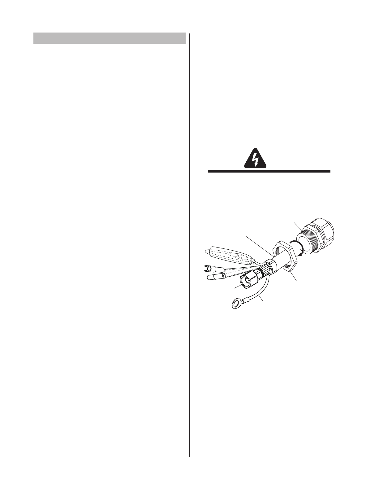
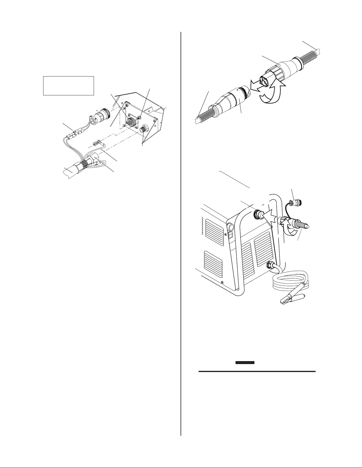
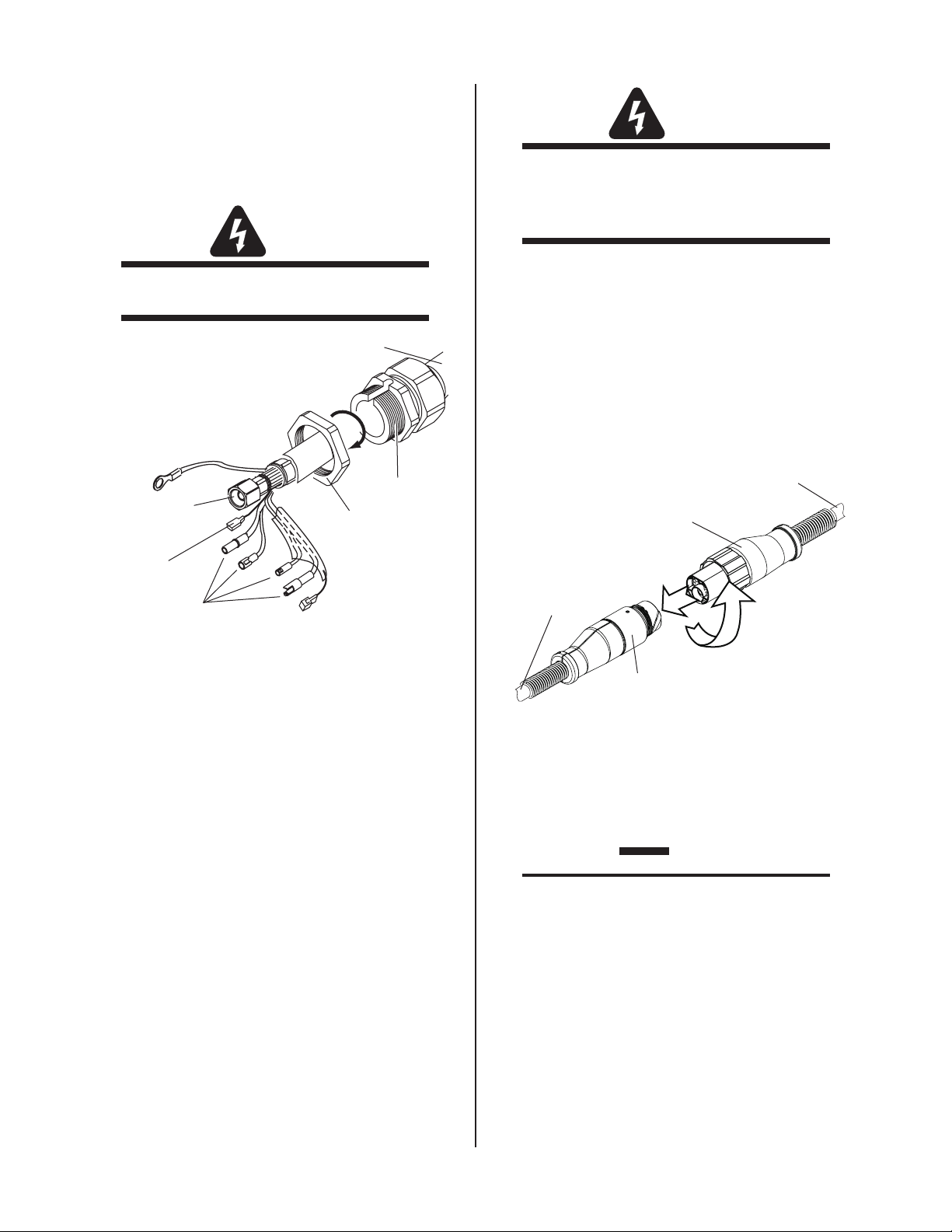
3.06 Connecting Torch
Thru-Hole Protector
Nut
Thru-Hole Protector
Torch Leads
Assembly or ATC Adapter
Art # A-03875
Negative /
Plasma Lead
Pilot Lead
A. Hand Systems
The Torch Leads must be properly connected to the Power
Supply for proper operation. If the torch leads or ATC
Adapter were not factory - installed, make all torch connections as required.
The instructions for connecting the Torch Leads to the
Power Supply vary depending on the type of leads connections. This sub - section covers connecting the Torch
for the following applications:
A. Hand Systems
B. Mechanized Machine Torch Systems with ATC Con-
nectors
C. Mechanized Machine Torch Systems with O2B Con-
nectors
D. Remote Pendant Control (Optional)
E. Automated Machine Torch Systems with ATC Connec-
tors
F. Automated Machine Torch Systems with O2B Connec-
tors
Torches with ATC connectors connect either to an ATC
Adapter which connects to the power supply bulkhead, or
to an ATC Receptacle which mounts to the power supply
front panel.
Torches with O2B fittings connect directly to the power
supply bulkhead. The connections to the bulkhead are the
same in both applications.
Follow Steps 1-8 to install either an ATC Adapter or a torch
with O2B fittings. Follow Step 9 to connect a torch with an
ATC connector to the ATC Adapter or to the panel-mounted
ATC receptacle.
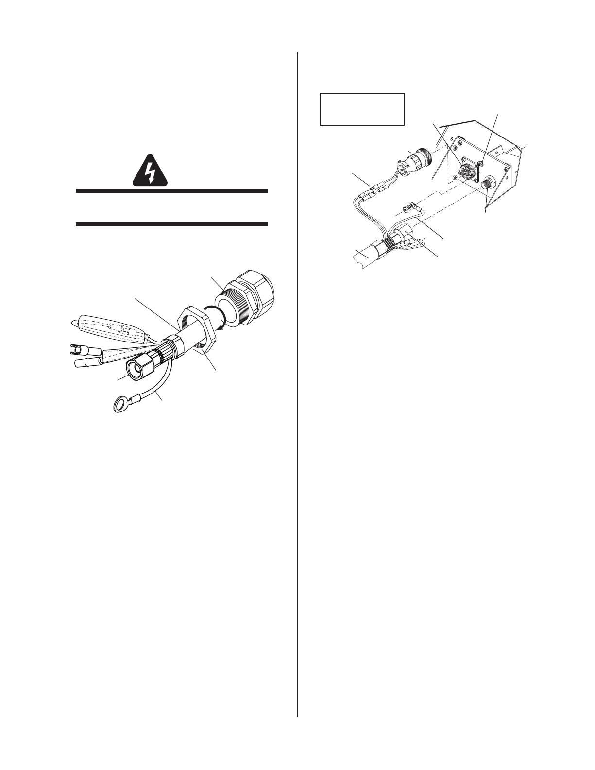
WARNING
Disconnect primary power at the source before
disassembling the torch or torch leads.
1. Remove the retaining nut from the Through - Hole
protector.
INSTALLATION 3-2 Manual 0-2962
Through - Hole Protector Nut Removal
2. Fit the torch leads or ATC Adapter end and the
Through - Hole protector into the hole in the unit.
Page 19
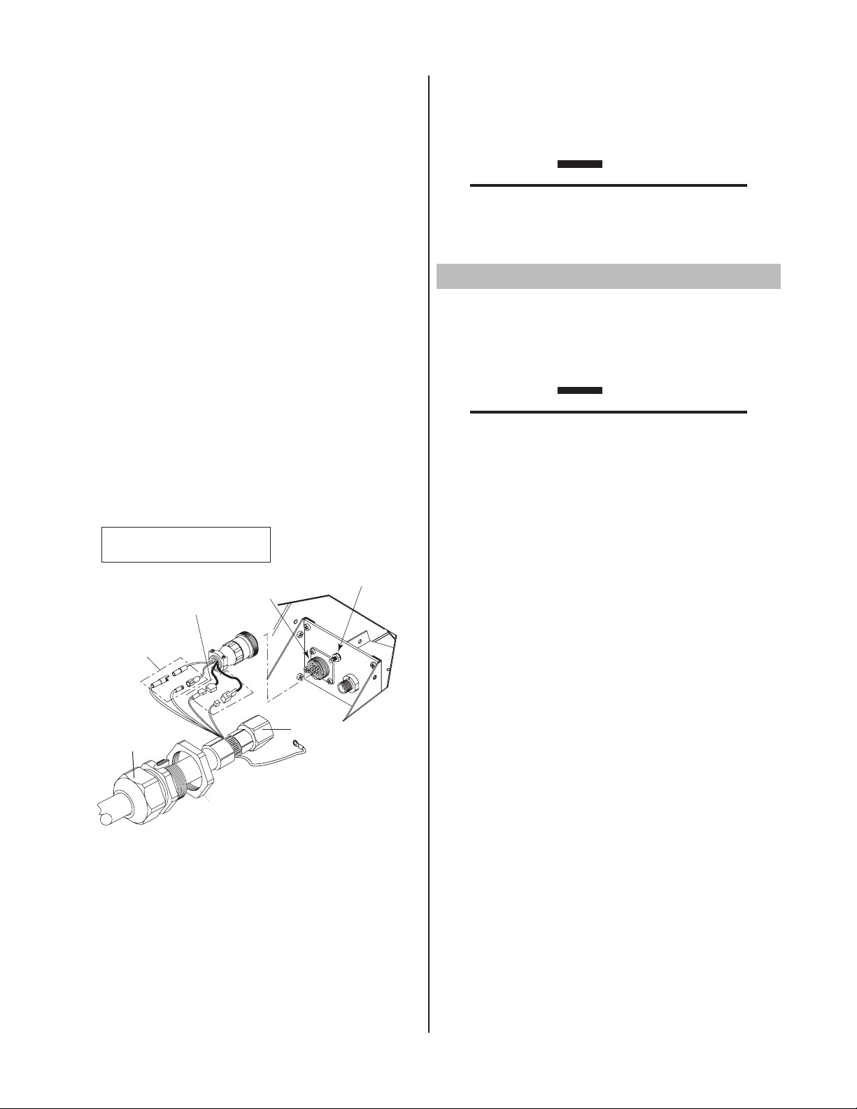
3. Secure the Through - Hole protector with the retain-
Adapter
Plug
Pilot Lead
Torch Leads
Assembly or
ATC Adapter
Negative/Plasma
Lead
Adapter
Connector
Pilot Lead Stud
Negative/Plasma Lead
Connection
A-03527
Control Circuit
Connectors
Note: Actual Bulkhead
configuration may
differ from that shown.
A-03627
1
2
ATC Male
Connector
ATC Adapter
Female Receptacle
Torch Leads
To
Power Supply
1
2
Control Cable
Connector (Machine
Torches Only)
ATC Male
Connector
ATC Female Receptacle
(Panel Mounted)
A-03602
ing nut removed earlier.
4. Connect the torch leads or ATC Adapter Negative
/ Plasma Lead to the bulkhead connection inside
the Power Supply as shown.
Bulkhead Connections - ATC Adapter or Hand Torch
Leads with O2B Fittings
Torch Connection - Torch Leads with ATC Male
Connector, Power Supply with ATC Adapter
Manual 0-2962 3-3 INSTALLATION
5. The Leads or ATC Adapter Assembly includes two
wires joined with mating connectors and covered
with an insulating sleeve. These wires must remain
joined and insulated. Connect the remaining torch
leads connectors to the mating connectors on the
Power Supply Adapter.
6. Remove the top nut and washer from the Pilot Stud.
7. Connect the pilot lead terminal to the stud and
secure with the nut and washer removed in the
above Step.
8. Tighten the Through - Hole protector onto the Torch
Leads or ATC Adapter Leads Assembly.
9. For torches with the ATC Connector, align the
torch leads male connector with the ATC female
receptacle. Push the male connector into the
female receptacle. The connectors should push
together with a very small amount of pressure.
Secure the connection by turning the locking nut
clockwise until it stops. DO NOT use the locking
nut to pull the connection together. Do not use
tools to secure the connection.
Torch Connection - Torch Leads with ATC Male
Connector, Power Supply with Panel-Mounted ATC
Receptacle
10. Check the torch for proper consumable parts.
CAUTION
The torch parts must correspond with the type
of operation. Refer to Section 4.04, Torch Parts
Selection.
Page 20
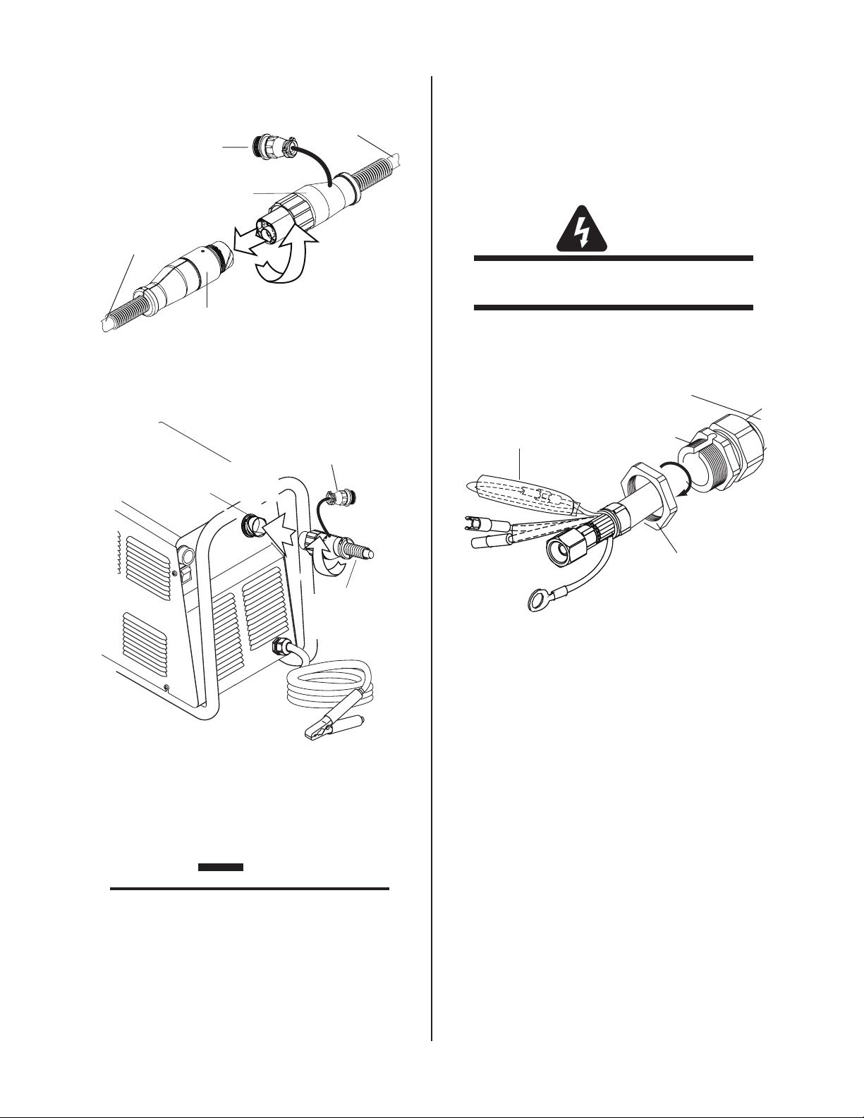
B. Mechanized Machine Torch Systems - Torches
Thru-Hole Protector
Nut
Thru-Hole Protector
Torch Leads
Assembly or ATC Adapter
Art # A-03875
Negative /
Plasma Lead
Pilot Lead
Adapter
Plug
Pilot Lead
Torch Leads
Assembly or
ATC Adapter
Negative/Plasma
Lead
Adapter
Connector
Pilot Lead Stud
Negative/Plasma Lead
Connection
A-03527
Control Circuit
Connectors
Note: Actual Bulkhead
configuration may
differ from that shown.
with ATC Connectors
Torches with ATC connectors connect either to an ATC
Adapter which connects to the power supply bulkhead,
or to a panel-mounted ATC Receptacle. Mechanized torch
leads with ATC connectors include a control cable connector to accept a remote pendant.
WARNING
Disconnect primary power at the source before
disassembling the torch or torch leads.
1. Remove the Through - Hole protector Nut from the
Through - Hole protector.
5. Connect the Control Circuit Connectors on the ATC
Adapter to the mating connectors on the Power
Supply Adapter.
6. Remove the top nut and washer from the Pilot Stud
on the power supply bulkhead.
7. Place the ATC Adapter Pilot lead terminal on onto
the stud and secure with the nut and washer removed in the above Step.
Through - Hole Protector Nut Removal
2. The ATC Adapter Assembly includes two wires
joined with mating connectors and covered with an
insulating sleeve. These wires must remain joined
and insulated.
3. Connect the ATC Adapter as follows:
a. Feed the end of the adapter lead and the
b. Tighten the Through - Hole protector Nut to
4. Connect the Adapter Negative / Plasma Lead to the
bulkhead connection inside the Power Supply.
Through - Hole protector into the hole in the
unit
secure the Through - Hole protector to the
Power Supply.
8. Tighten the Through - Hole protector onto the ATC
Adapter leads.
9. Connect the torch leads male connector to the ATC
female receptacle. The connectors should push
together with a very small amount of pressure.
Secure the connection by turning the locking nut
clockwise until it stops. DO NOT use the locking
nut to pull the connection together. Do not use
tools to secure the connections.
INSTALLATION 3-4 Manual 0-2962
Page 21
10. Connect the remote pendant adapter to the Remote
A-03582
1
2
Control Cable
Connector (Machine
Torches Only)
ATC Male
Connector
ATC Adapter
Female Receptacle
Torch Leads
To
Power Supply
1
2
Control Cable
Connector (Machine
Torches Only)
ATC Male
Connector
ATC Female Receptacle
(Panel Mounted)
A-03602
Through - Hole
Protector Nut
Through - Hole
Protector
Torch Leads
Assembly or ATC Adapter
Art # A-03877
Remove Tie Wrap,
Remove Insulator,
Disconnect Wires
Pilot Lead
Control Cable Connector.
Torch Connection - Torch Leads with ATC Male
Connector, Power Supply with ATC Adapter
C. Mechanized Machine Torch Systems - Torches
with O2B Connectors
Torches with O2B connectors connect directly to the
power supply bulkhead. Mechanized torch leads with O2B
connectors require a remote pendant adapter to accept a
remote pendant.
WARNING
Disconnect primary power at the source before
disassembling the torch or torch leads.
1. Remove the Through - Hole protector Nut from the
Through - Hole protector.
Connector, Power Supply with Panel-Mounted ATC
11. Check the torch for proper consumable parts.
Torch Connection - Torch Leads with ATC Male
Receptacle
The torch parts must correspond with the type
of operation. Refer to Section 4.04, Torch Parts
CAUTION
Selection.
Through - Hole Protector Nut Removal
2. The leads Assembly includes two wires joined with
mating connectors and covered with an insulating
sleeve. Remove the tie wrap and insulating sleeve.
Disconnect the two joined wires.
3. Feed the end of the torch leads and the Through Hole protector into the hole in the unit.
4. Route the wire harness on the Remote Pendant
Adapter through the Through - Hole protector and
Through - Hole protector Nut. Tighten the Through
- Hole protector Nut to secure the Through - Hole
protector to the Power Supply.
5. Connect the Negative / Plasma lead to the bulkhead
connection inside the power supply.
Manual 0-2962 3-5 INSTALLATION
Page 22
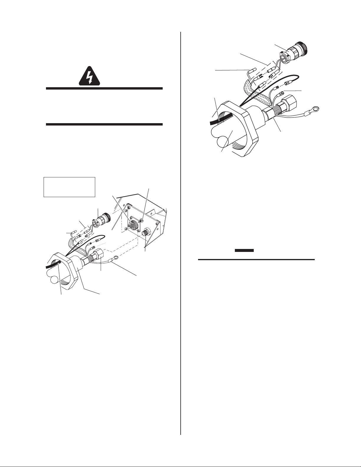
6. Connect the control circuit connectors on the Torch
A-03675
Torch Lead
Assembly
Control Circuit
Connectors
Open
Open
Power Supply
Adapter
Pilot LeadNegative/Plasma
Lead
Adapter
Connector
Pilot Lead Stud
Negative/Plasma
Lead Connection
Note: Actual Bulkhead
configuration may
differ from that shown.
Remote Pendant
Adapter Wire Harness
Remote Pendant
Adapter Wire
Harness
A-03676
Pilot Lead
Torch Lead
Assembly
Negative/Plasma
Lead
Control Circuit
Connectors
Open
Open
Power Supply
Adapter
Leads to the mating connectors on the Remote
Pendant Adapter and Power Supply Adapter (see
Warning).
WARNING
There are two additional connectors that are
not used and must be taped out of the way to
prevent contacting the Negative / Plasma or
Pilot Leads.
7. Remove the top nut and washer from the Pilot Stud
on the power supply bulkhead.
8. Place the Torch Leads Pilot lead terminal on onto
the stud and secure with the nut and washer removed in the above Step.
Bulkhead Connection Detail - Unshielded Machine Torch
with O2B Fittings and Remote Pendant Adapter
10. Tighten the Through - Hole protector onto the Torch
Leads or ATC Adapter Leads Assembly.
Bulkhead Connection - Unshielded Machine Torch with
O2B Fittings and Remote Pendant Adapter
9. Connect the Torch Leads connectors and the
remote pendant adapter connector to the power
supply adapter as shown.
11. Connect the remote pendant to the remote pendant
adapter.
12. Check the torch for proper consumable parts.
CAUTION
The torch parts must correspond with the type
of operation. Refer to Section 4.04, Torch Parts
Selection.
D. Remote Pendant Control (Optional)
In mechanized applications an Adapter connects the
remote pendant control to the Power Supply.
Connect the remote pendant control cable to the torch
leads by aligning the control cable connector with
the adapter on the torch leads. Press the connector
into the adapter. Turn the locking ring to secure the
connection.
INSTALLATION 3-6 Manual 0-2962
Page 23
E. Automated Machine Torch Systems with ATC
Strain Relief
Nut
Strain Relief
Shielded ATC Adapter
Pilot Lead
Negative/Plasma
Lead
Torch Control
Connectors
Shield
Connector
Shield
Connector
A-03677
A-03627
1
2
ATC Male
Connector
ATC Adapter
Female Receptacle
Torch Leads
To
Power Supply
Connectors
Torches with shielded leads and ATC connectors connect
to a shielded ATC Adapter which connects to the power
supply bulkhead.
WARNING
Disconnect primary power at the source before
disassembling the torch or torch leads.
WARNING
The Shielded ATC Adapter includes two connec
tors that are not used and must be taped out
of the way to prevent contacting the Negative
/ Plasma or Pilot Leads.
8. Tighten the Through - Hole protector onto the ATC
Adapter leads.
9. Connect the torch leads male connector to the ATC
female receptacle. The connectors should push
together with a very small amount of pressure.
Secure the connection by turning the locking nut
clockwise until it stops. DO NOT use the locking
nut to pull the connection together. Do not use
tools to secure the connections.
Manual 0-2962 3-7 INSTALLATION
Through - Hole protector Nut Removal
1. Remove the Through - Hole protector Nut from
the Through - Hole protector. Inside the Power
Supply Bulkhead area, route the connectors on the
free end of the Adapter through the Through - Hole
protector Nut.
2. Fit the ATC Adapter end and the Through - Hole
protector into the hole in the unit.
3. Secure the Through - Hole protector with the retaining nut removed earlier.
4. Connect the ATC Adapter Negative / Plasma Lead to
the bulkhead connection inside the Power Supply.
5. Remove the top nut and washer from the Pilot Stud.
6. Connect the pilot lead terminal to the stud and secure with the nut and washer removed previously.
7. Connect the ATC Adapter connectors to the power
supply adapter.
Torch Connection - Torch Leads with ATC Male
Connector, Power Supply with ATC Adapter
10. Check the torch for proper consumable parts.
CAUTION
The torch parts must correspond with the type
of operation. Refer to Section 4.04, Torch Parts
Selection.
Page 24
F. Automated Machine Torch Systems with O2B
Adapter
Connector
Pilot Lead Stud
Strain Relief
Nut
Strain Relief
Shielded Torch Leads
with O2B Connector
Pilot Lead
Negative/Plasma
Lead
Torch Control
Connectors
Shield
Connectors
A-03678
Power Supply Bulkhead
May Differ from Type Shown
Connectors
8. Tighten the Through - Hole protector onto the ATC
Adapter leads.
Torches with shielded leads and O2B connectors connect
directly to the power supply bulkhead.
1. Remove the Through - Hole protector Nut from the
Through - Hole protector. Inside the Power Supply
Bulkhead area, route the connectors on the free
end of the torch leads through the Through - Hole
protector Nut.
2. Fit the leads ends and the Through - Hole protector
into the hole in the unit.
3. Secure the Through - Hole protector with the retaining nut removed earlier.
4. Connect the Negative / Plasma Lead to the bulkhead
connection inside the Power Supply.
5. Remove the top nut and washer from the Pilot Stud.
6. Connect the pilot lead terminal to the stud and secure with the nut and washer removed previously.
7. Connect the connectors to the power supply
adapter as shown.
9. Check the torch for proper consumable parts.
CAUTION
The torch parts must correspond with the type
of operation. Refer to Section 4.04, Torch Parts
Selection.
3.07 Gas Connection
A. Connection
Connect the gas, compressed air only, to the Power
Supply as described in the Power Supply Manual.
CAUTION
Air supply must be free of oil, moisture, and
other contaminants. Excessive oil and mois
ture may cause double - arcing, rapid tip wear,
or even complete torch failure. Contaminants
may cause poor cutting performance and rapid
electrode wear.
-
Bulkhead Connections - Shielded Machine Torch Leads
with O2B Connectors
B. Checking Air Quality
To test the quality of air, place a welding filter lens
in front of the torch and turn on the gas. Any oil or
moisture in the air will be visible on the lens. Do not
initiate an arc!
C. Filtering
An in - line pneumatic dryer & evaporator type air filter,
capable of filtering to at least 5 microns, is required
when using air from a compressor. This type filter
will insure that moisture, oil, dirt, chips, rust particles,
and other contaminants from the supply hose do not
enter the torch. For highly automated applications, a
refrigerated drier may be used.
INSTALLATION 3-8 Manual 0-2962
Page 25
SECTION 4:
!
OPERATION
4.01 Introduction
This section provides a description of the SL60 and SL100
Torch Assemblies followed by operating procedures.
E. Power On
Place the ON - OFF Switch on the Power Supply to the
ON position. If the RUN - SET - LATCH , RUN - SET
or RUN - RAPID AUTO RESTART - SET Switch is in
SETposition,gas willow. Iftheswitchis inRUN
positiontherewillbenogasow.
F. RUN - SET - LATCH , RUN - SET or RUN - RAPID
AUTO RESTART Switch
4.02 Functional Overview
The Torch is designed to operate with various Power Supplies to provide a plasma cutting system which can cut
most metals. With gouging torch parts the torch can be
used for plasma arc gouging.
NOTE
Refer to Appendix Pages for additional informa
tion as related to the Power Supply used.
-
4.03 Getting Started
Follow this procedure at the beginning of each shift:
WARNING
Disconnect primary power at the source before
assembling or disassembling power supply,
torch parts, or torch and leads assemblies.
A. Torch Parts
If the RUN - SET - LATCH , RUN - SET or RUN - RAPID
AUTO RESTART - SET switch is in SET position, gas
willow.IftheswitchisinRUNpositiontherewill
benogasow.
G. Current Output Level
At the Power Supply, set the desired current output
level. For drag cutting set the control at 40 amps or
less only.
WARNING
Maximum current is 60 Amps for SL60 Torches,
or 100 Amps for SL100 Torches. Operation of
this torch at higher outputs may damage the
torch, the leads, the components, or the Power
Supply. DO NOT operate the SL60 torch at
more than 60 Amps, or the SL100 torch at more
than 100 Amps.
H. Pressure Settings
Check the torch for proper assembly. Install proper
torch parts for the desired application (refer to Section
4.04, Torch Parts Selection).
B. Input Power
Check the power source for proper input voltage.
Close main disconnect switch or plug unit in to supply
primary power to the system.
C. Work Cable
Check for a solid cable connection to the workpiece.
D. Gas Supply
Select desired single gas supply. Make sure gas
sources meet requirements (see Note). Check connections and turn gas supply on.
NOTE
Refer to Appendix Pages for additional informa
tion as related to the Power Supply used.
Place the RUN - SET - LATCH , RUN - SET or RUN
- RAPID AUTO RESTART - SET switch to the SET position. Adjust the gas pressure control on the Power
Supply for the proper gas pressure. Refer to Appendix
Pages for gas pressure and other specifics.
I. Ready for Operation
Return the RUN - SET - LATCH , RUN - SET or RUN RAPID AUTO RESTART - SET switch to RUN position.
NOTES
For general cutting, use the RUN position
which provides normal torch operation where
the torch switch must be held throughout the
main arc transfer.
For specific applications, use the LATCH posi
tion where the torch switch can be released
after the main arc transfer. The torch remains
-
activated until the main arc breaks from the
workpiece.
-
Manual 0-2962 4-1 OPERATION
Page 26
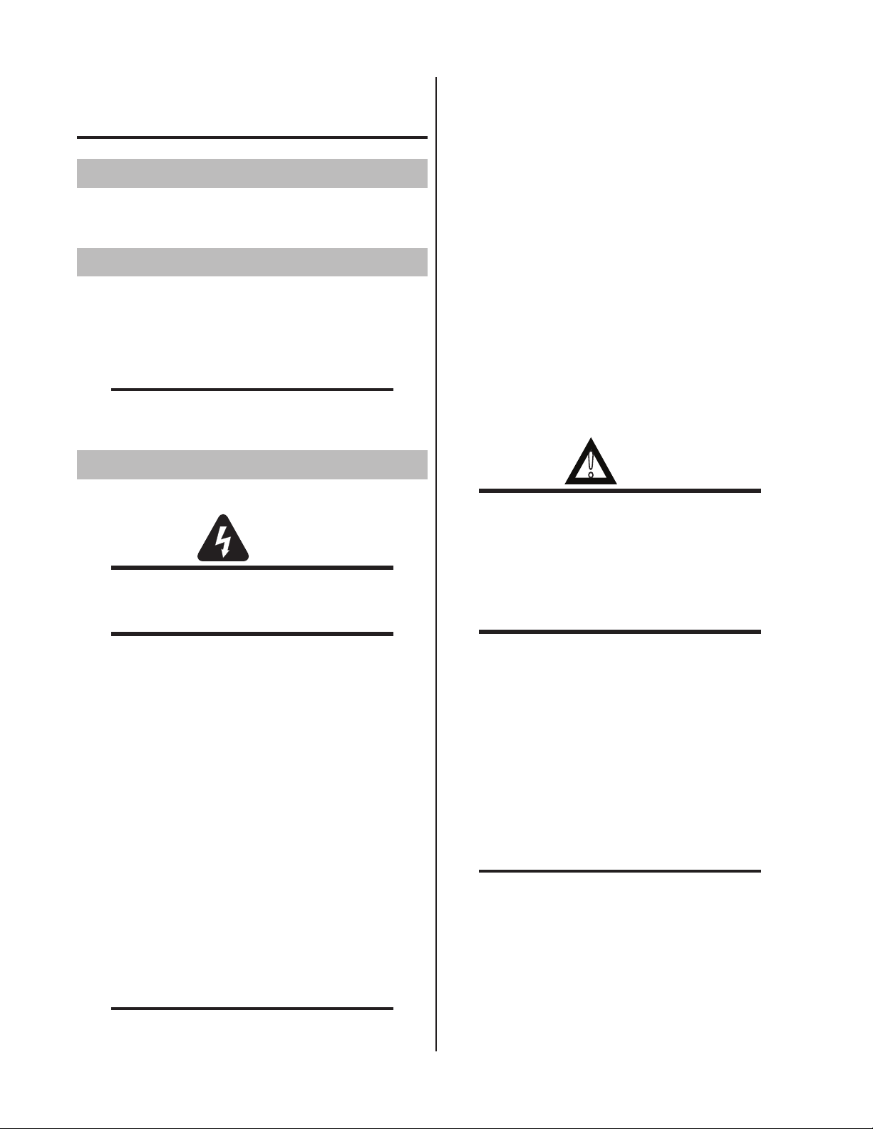
Refer to Appendix 1 for a typical detailed block
Art # A-03417
Electrode
Start Cartridge
Tip
Shield Cup
Assembly
Torch Head
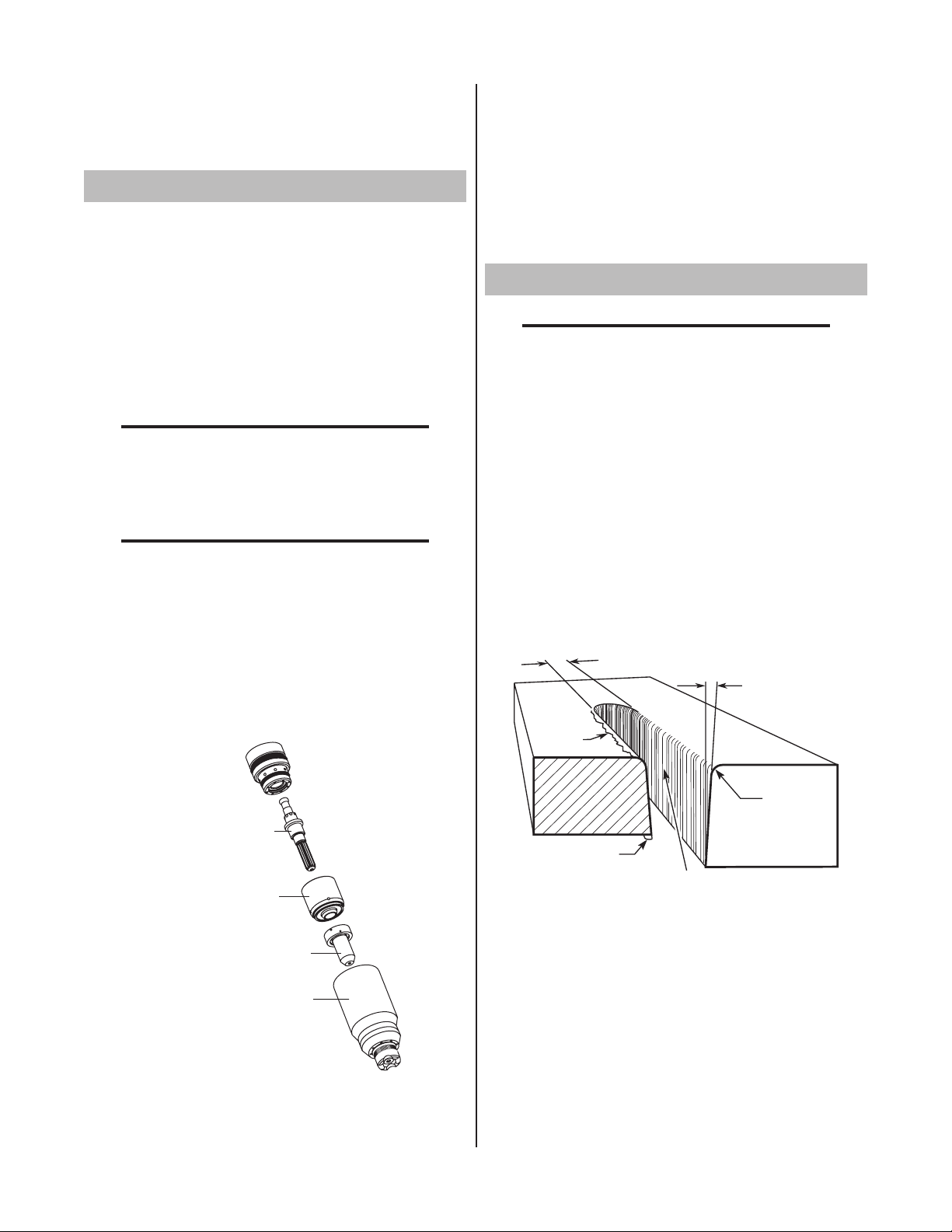
Kerf Width
Cut Surface
Bevel Angle
Top Edge
Rounding
Cut Surface
Drag Lines
Dross
Build-Up
Top
Spatter
A-00007
diagram of Sequence of Operation.
3. Install the replacement Electrode by pushing it straight
into the torch head until it clicks.
The system is now ready for operation.
4.04 Torch Parts Selection
Depending on the type of operation to be done determines
the torch parts to be used.
Type of operation:
Drag cutting, standoff cutting or gouging
Torch parts:
Shield Cup, Cutting Tip, Electrode and Starter
Cartridge
NOTE
Refer to Section 6 and the Appendix Pages for
additional information on torch parts.
Change the torch parts for a different operation as follows:
NOTE
The shield cup holds the tip and starter car
tridge in place. Position the torch with the
shield cup facing upward to keep these parts
from falling out when the cup is removed.
-
4. Install the starter cartridge and desired tip for the op-
eration into the torch head.
5. Hand tighten the shield cup assembly until it is seated
on the torch head. If resistance is felt when installing
the cup, check the threads before proceeding.
4.05 Cut Quality
NOTES
Cut quality depends heavily on setup and pa
rameters such as torch standoff, alignment with
the workpiece, cutting speed, gas pressures,
and operator ability.
Refer to Appendix Pages for additional informa
tion as related to the Power Supply used.
Cut quality requirements differ depending on application.
For instance, nitride build - up and bevel angle may be
major factors when the surface will be welded after cutting.
Dross - free cutting is important when finish cut quality
is desired to avoid a secondary cleaning operation. The
following cut quality characteristics are illustrated in the
following figure:
-
-
1. Unscrew and remove the shield cup assembly from the
torch head.
2. Remove the Electrode by pulling it straight out of the
Torch Head.
Cut Quality Characteristics
A. Cut Surface
The desired or specified condition (smooth or rough)
of the face of the cut.
B. Nitride Build - Up
Torch Parts (Drag Shield Cap & Shield Cup Body Shown)
OPERATION 4-2 Manual 0-2962
Nitride deposits can be left on the surface of the cut
when nitrogen is present in the plasma gas stream.
These buildups may create difficulties if the material
is to be welded after the cutting process.
Page 27

C. Bevel Angle
Right Side
Cut Angle
Left Side
Cut Angle
A-00512
A. Piloting
The angle between the surface of the cut edge and
a plane perpendicular to the surface of the plate. A
perfectly perpendicular cut would result in a 0° bevel
angle.
D. Top - Edge Rounding
Rounding on the top edge of a cut due to wearing from
the initial contact of the plasma arc on the workpiece.
E. Bottom Dross Buildup
Molten material which is not blown out of the cut area
and resolidifies on the plate. Excessive dross may
require secondary cleanup operations after cutting.
F. Kerf Width
The width of the cut (or the width of material removed
during the cut).
G. Top Spatter (Dross)
Top spatter or dross on the top of the cut caused by
slow travel speed, excess cutting height, or cutting tip
whose orifice has become elongated.
4.06 General Cutting Information
WARNINGS
Disconnect primary power at the source before
disassembling the power supply, torch, or torch
leads.
Piloting is harder on parts life than actual cutting
because the pilot arc is directed from the electrode to
the tip rather than to a workpiece. Whenever possible,
avoid excessive pilot arc time to improve parts life.
B. Torch Standoff
Improper standoff (the distance between the torch tip
and workpiece) can adversely affect tip life as well as
shield cup life. Standoff may also significantly affect
the bevel angle. Reducing standoff will generally result
in a more square cut.
C. Edge Starting
For edge starts, hold the torch perpendicular to the
workpiece with the front of the tip near (not touching)
the edge of the workpiece at the point where the cut
is to start. When starting at the edge of the plate, do
notpauseattheedgeandforcethearcto"reach"for
the edge of the metal. Establish the cutting arc as
quickly as possible.
D. Direction of Cut
In the torches, the plasma gas stream swirls as it
leaves the torch to maintain a smooth column of gas.
This swirl effect results in one side of a cut being more
square than the other. Viewed along the direction of
travel, the right side of the cut is more square than
the left.
Frequently review the Important Safety Pre
cautions at the front of this manual. Be sure
the operator is equipped with proper gloves,
clothing, eye and ear protection. Make sure no
part of the operator’s body comes into contact
with the workpiece while the torch is activated.
Side Characteristics Of Cut
CAUTION
To make a square - edged cut along an inside diameter
Sparks from the cutting process can cause
damage to coated, painted, and other surfaces
such as glass, plastic and metal.
NOTE
Handle torch leads with care and protect them
from damage.
of a circle, the torch should move counterclockwise
around the circle. To keep the square edge along
an outside diameter cut, the torch should travel in a
clockwise direction.
Manual 0-2962 4-3 OPERATION
Page 28

E. Dross
A-00024_AB
Shield Cup
Torch
Standoff Distance
1/8" - 3/8" (3 - 9mm)
When dross is present on carbon steel, it is com-
monlyreferredtoaseither“highspeed,slowspeed,
ortopdross”. Drosspresentontopof theplateis
normally caused by too great a torch to plate distance.
"Topdross"isnormallyveryeasytoremoveandcan
oftenbewipedoffwithaweldingglove."Slowspeed
dross"isnormallypresentonthebottomedgeofthe
plate. It can vary from a light to heavy bead, but does
not adhere tightly to the cut edge, and can be easily
scrapedoff."Highspeeddross"usuallyformsanarrow bead along the bottom of the cut edge and is very
difficult to remove. When cutting a troublesome steel,
it is sometimes useful to reduce the cutting speed to
produce"slowspeeddross".Anyresultantcleanupcan
be accomplished by scraping, not grinding.
4.07 Hand Torch Operation
A. Standoff Cutting With Hand Torch
NOTE
2. Depending on the cutting operation, do one of the
following:
a. For edge starts, hold the torch perpendicular
to the workpiece with the front of the tip on the
edge of the workpiece at the point where the
cut is to start.
b. For standoff cutting, hold the torch 1/8 - 3/8 in
(3-9 mm) from the workpiece as shown below.
For best performance and parts life, always
use the correct parts for the type of operation.
1. The torch can be comfortably held in one hand
or steadied with two hands. Position the hand to
press the Trigger on the torch handle. With the
hand torch, the hand may be positioned close to
the torch head for maximum control or near the
back end for maximum heat protection. Choose
the holding technique that feels most comfortable
and allows good control and movement.
NOTE
The tip should never come in contact with the
workpiece except during drag cutting opera
-
tions.
Standoff Distance
3. Hold the torch away from your body.
4. Slide the trigger release toward the back of the
torch handle while simultaneously squeezing the
trigger. The pilot arc will start.
Trigger
Trigger Release
A-02986
5. Bring the torch within transfer distance to the work.
The main arc will transfer to the work, and the pilot
arc will shut off.
NOTE
Thegaspreowandpostowareacharacter
istic of the power supply and not a function of
the torch.
OPERATION 4-4 Manual 0-2962
Page 29

3
4
Art # A-03383
Tr igger
2
1
Tr igger Release
Shield Cup
Workpiece
Standoff Guide
Art # A-04034
Torch Tip
A-03539
Non-Conductive
Straight Edge
Cutting Guide
6. Cut as usual. Simply release the trigger assembly
to stop cutting.
7. Follow normal recommended cutting practices as
provided in the power supply operator's manual.
NOTE
When the shield cup is properly installed, there
is a slight gap between the shield cup and the
torch handle. Gas vents through this gap as
part of normal operation. Do not attempt to
force the shield cup to close this gap. Forcing
the shield cup against the torch head or torch
handle can damage components.
8. For a consistent standoff height from the workpiece, install the standoff guide by sliding it onto
the torch shield cup. Install the guide with the
legs at the sides of the shield cup body to maintain
good visibility of the cutting arc. During operation,
position the legs of the standoff guide against the
workpiece.
B. Shield Cup With Straight Edge
The drag shield cup can be used with a nonconductive
straight edge to make straight cuts by hand.
WARNING
The straight edge must be non - conductive.
Using Drag Shield Cup With Straight Edge
The crown shield cup functions best when cutting
3/16 inch (4.7 mm) solid metal with relatively smooth
surface.
C. Drag Cutting With a Hand Torch
Drag cutting works best on metal 3/16" (4.7 mm)
thick or less.
NOTE
For best parts performance and life, always
use the correct parts for the type of operation.
1. Install the drag cutting tip and set the output current to 35 amps or less.
2. The torch can be comfortably held in one hand
or steadied with two hands. Position the hand to
press the Trigger on the torch handle. With the
hand torch, the hand may be positioned close to
the torch head for maximum control or near the
back end for maximum heat protection. Choose
the holding technique that feels most comfortable
and allows good control and movement.
4. Keep the torch in contact with the workpiece during
the cutting cycle.
5. Hold the torch away from your body.
6. Slide the trigger release toward the back of the
torch handle while simultaneously squeezing the
trigger. The pilot arc will start.
Manual 0-2962 4-5 OPERATION
Page 30

Trigger
3
4
Art # A-03383
Tr igger
2
1
Tr igger Release
Trigger Release
A-02986
7. Bring the torch within transfer distance to the work.
The main arc will transfer to the work, and the pilot
arc will shut off.
NOTE
Thegaspreowandpostowareacharacter
istic of the power supply and not a function of
the torch.
D. Piercing With Hand Torch
1. The torch can be comfortably held in one hand
or steadied with two hands. Position the hand to
press the Trigger on the torch handle. With the
hand torch, the hand may be positioned close to
the torch head for maximum control or near the
back end for maximum heat protection. Choose the
technique that feels most comfortable and allows
good control and movement.
NOTE
The tip should never come in contact with the
workpiece except during drag cutting opera
tions.
2. Angle the torch slightly to direct blowback particles
away from the torch tip (and operator) rather than
directly back into it until the pierce is complete.
3. In a portion of the unwanted metal start the pierce
off the cutting line and then continue the cut onto
the line. Hold the torch perpendicular to the workpiece after the pierce is complete.
-
OPERATION 4-6 Manual 0-2962
8. Cut as usual. Simply release the trigger assembly
to stop cutting.
9. Follow normal recommended cutting practices as
provided in the power supply operator's manual.
NOTE
When the shield cup is properly installed, there
is a slight gap between the shield cup and the
torch handle. Gas vents through this gap as
part of normal operation. Do not attempt to
force the shield cup to close this gap. Forcing
the shield cup against the torch head or torch
handle can damage components.
4. Hold the torch away from your body.
5. Slide the trigger release toward the back of the
torch handle while simultaneously squeezing the
trigger. The pilot arc will start.
Trigger
Trigger Release
A-02986
6. Bring the torch within transfer distance to the work.
The main arc will transfer to the work, and the pilot
arc will shut off.
NOTES
Thegaspreowandpostowareacharacter
istic of the power supply and not a function of
the torch.
When the shield cup is properly installed, there
is a slight gap between the shield cup and the
torch handle. Gas vents through this gap as
part of normal operation. Do not attempt to
force the shield cup to close this gap. Forcing
the shield cup against the torch head or torch
handle can damage components.
Page 31

7. Clean spatter and scale from the shield cup and the
A-02585
Workpiece
Square
Pinch Block
Assembly
Standoff Distance
Straight Arc
Trailing Arc
Leading Arc
Direction of Torch Travel
A-02586
tip as soon as possible. Spraying the shield cup in
anti - spatter compound will minimize the amount
of scale which adheres to it.
4.08 Machine Torch Operation
A. Cutting With Machine Torch
The machine torch can be activated by remote control
pendant or by a remote interface device such as CNC.
1. Use a square to check that the torch is perpendicular to the workpiece to obtain a clean, vertical cut.
3. Trailing Arc
The trailing arc is directed in the opposite direction
as torch travel.
2. To start a cut at the plate edge, position the center
of the torch along the edge of the plate.
B. Travel Speed
Proper travel speed is indicated by the trail of the arc
which is seen below the plate. The arc can be one of
the following:
1. Straight Arc
A straight arc is perpendicular to the workpiece
surface. This arc is generally recommended for the
best cut using air plasma on stainless or aluminum.
2. Leading Arc
The leading arc is directed in the same direction as
torch travel. A five degree leading arc is generally
recommended for air plasma on mild steel.
Checking Alignment
Machine Torch Operation
For optimum smooth surface quality, the travel speed
should be adjusted so that only the leading edge of
the arc column produces the cut. If the travel speed
is too slow, a rough cut will be produced as the arc
moves from side to side in search of metal for transfer.
Travel speed also affects the bevel angle of a cut. When
cutting in a circle or around a corner, slowing down
the travel speed will result in a squarer cut. The power
source output should be reduced also. Refer to the
appropriate Control Module Operating Manual for any
Corner Slowdown adjustments that may be required.
Manual 0-2962 4-7 OPERATION
Page 32

C. Piercing With Machine Torch
To pierce with a machine torch, the arc should be
started with the torch positioned as high as possible
above the plate while allowing the arc to transfer and
pierce. This standoff helps avoid having molten metal
blow back onto the front end of the torch.
Refer to Appendix Pages for cutting speed
chart information as related to the Power Supply used.
4.10 Gouging
When operating with a cutting machine, a pierce or
dwell time is required. Torch travel should not be
enabled until the arc penetrates the bottom of the
plate. As motion begins, torch standoff should be
reduced to the recommended 1/8 - 1/4 inch (3-6 mm)
distance for optimum speed and cut quality. Clean
spatter and scale from the shield cup and the tip as
soon as possible. Spraying or dipping the shield cup
in anti - spatter compound will minimize the amount
of scale which adheres to it.
4.09 Recommended Cutting Speeds
Cutting speed depends on material, thickness, and the
operator’s ability to accurately follow the desired cut line.
The following factors may have an impact on system
performance:
• Torchpartswear
• Airquality
• Linevoltageuctuations
• Torchstandoffheight
• Properworkcableconnection
NOTES
This information represents realistic expecta
tions using recommended practices and well
- maintained systems. Actual speeds may vary
up to 50% from those shown.
-
WARNINGS
Be sure the operator is equipped with proper
gloves, clothing, eye and ear protection and
that all safety precautions at the front of this
manual have been followed. Make sure no part
of the operator’s body comes in contact with the
workpiece when the torch is activated.
Disconnect primary power to the system be
fore disassembling the torch, leads, or power
supply.
CAUTIONS
Sparks from plasma gouging can cause damage to coated, painted or other surfaces such
as glass, plastic, and metal.
Check torch parts. The torch parts must cor
respond with the type of operation. Refer to
Section 4.04, Torch Parts Selection.
A. Gouging Parameters
Gouging performance depends on parameters such as
torch travel speed, current level, lead angle (the angle
between the torch and workpiece), and the distance
between the torch tip and workpiece (standoff).
B. Torch Travel Speed
NOTE
-
-
Refer to Appendix Pages for additional informa
-
tion as related to the Power Supply used.
Optimum torch travel speed is dependent on current
setting, lead angle, and mode of operation (hand or
machine torch).
OPERATION 4-8 Manual 0-2962
Page 33

C. Current Setting
35°
Workpiece
Torch Head
Standoff Height
A-00941_AB
Current settings depend on torch travel speed, mode
of operation (hand or machine torch), and the amount
of material to be removed.
D. Lead Angle
The angle between the torch and workpiece depends
on the output current setting and torch travel speed.
At 80 amps, the recommended lead angle is 35°. At
a lead angle greater than 45° the molten metal will
not be blown out of the gouge and may be blown back
onto the torch. If the lead angle is too small (less than
35°), less material may be removed, requiring more
passes. In some applications, such as removing welds
or working with light metal, this may be desirable.
E. Standoff Distance
The tip to work distance affects gouge quality and
depth. Standoff distance of 1/8 - 1/4 inch (3 - 6 mm)
allows for smooth, consistent metal removal. Smaller
standoff distances may result in a severance cut rather
than a gouge. Standoff distances greater than 1/4 inch
(6 mm) may result in minimal metal removal or loss
of transferred main arc.
F. Slag Buildup
Slag generated by gouging on materials such as carbon and stainless steels, nickels, and alloyed steels,
can be removed easily in most cases. Slag does not
obstruct the gouging process if it accumulates to the
side of the gouge path. However, slag build - up can
cause inconsistencies and irregular metal removal if
large amounts of material build up in front of the arc.
The build - up is most often a result of improper travel
speed, lead angle, or standoff height.
Gouging Angle and Standoff Distance
Manual 0-2962 4-9 OPERATION
Page 34

OPERATION 4-10 Manual 0-2962
Page 35

SECTION 5:
5.02 General Torch Maintenance
SERVICE
5.01 Introduction
This section describes basic maintenance procedures performable by operating personnel. No other adjustments or
repairs are to be attempted by other than properly trained
personnel.
WARNINGS
Disconnect primary power at the source before
disassembling the torch or torch leads.
Frequently review the Important Safety Pre
cautions at the front of this Manual. Be sure
the operator is equipped with proper gloves,
clothing, eye and ear protection. Make sure no
part of the operator’s body comes into contact
with the workpiece while the torch is activated.
CAUTION
Sparks from the cutting process can cause
damage to coated, painted, and other surfaces
such as glass, plastic and metal.
-
A. Cleaning Torch
Even if precautions are taken to use only clean air with
a torch, eventually the inside of the torch becomes
coated with residue. This buildup can affect the pilot
arc initiation and the overall cut quality of the torch.
WARNINGS
Disconnect primary power to the system before
disassembling the torch or torch leads.
DO NOT touch any internal torch parts while the
AC indicator light of the Power Supply is ON.
The inside of the torch should be cleaned with electrical
contact cleaner using a cotton swab or soft wet rag. In
severe cases, the torch can be removed from the leads
and cleaned more thoroughly by pouring electrical
contact cleaner into the torch and blowing it through
with compressed air.
CAUTION
Dry the torch thoroughly before reinstalling.
NOTE
Handle torch leads with care and protect them
from damage.
Manual 0-2962 5-1 SERVICE
Page 36

B. O-Ring Lubrication
ATC Male Connector
Art #A-03791
Gas Fitting
O-Ring
5.03 Common Operating Faults
This section applies only to torches withATC connectors.
An o-ring on the Torch ATC Male Connector requires
lubrication on a regular basis, depending on how frequently the torch is disconnected and re-connected.
This will allow the o-ring to remain pliable and provide
a proper seal. The o-ring will dry out, becoming hard
and cracked, if the o-ring lubricant is not used on a
regular basis. This can lead to potential performance
problems.
It is recommended to apply a very light film of o-ring
lubricant (Catalog # 8-4025) to the o-ring on a weekly
basis.
NOTE
DO NOT use other lubricants or grease, they
may not be designed to operate within high
temperatures or may contain “unknown ele
-
ments” that may react with the atmosphere.
This reaction can leave contaminants inside
the torch. Either of these conditions can lead
to inconsistent performance or poor parts life.
The following lists the more common cutting faults and
possible causes:
1. Insufficient Penetration
a. Cutting speed too fast
b. Torch tilted too much
c. Metal too thick
d. Worn torch parts
e. Cutting current too low
f. Non - Genuine Thermal Dynamics Parts
2. Main Arc Extinguishes
a. Cutting speed too slow
b. Torch standoff too high from workpiece
c. Cutting current too high
d. Work cable disconnected
e. Worn torch parts
f. Non - Genuine Thermal Dynamics Parts
3. Excessive Dross Formation
a. Cutting speed too slow
b. Torch standoff too high from workpiece
c. Worn torch parts
d. Improper cutting current
e. Non - Genuine Thermal Dynamics Parts
4. Short Torch Parts Life
a. Oil or moisture in air source
b. Exceeding system capability (material too thick)
c. Excessive pilot arc time
d. Airowtoolow(incorrectpressure)
e. Improperly assembled torch
f. Non - Genuine Thermal Dynamics Parts
SERVICE 5-2 Manual 0-2962
Page 37

5.04 Inspection and Replacement of
Art # A-03417
Electrode
Start Cartridge
Tip
Shield Cup
Assembly
Torch Head
Drag Shield Cap
Shield
Cup Body
O-Ring No. 8-3488
Art # A-03878
Good Tip
Worn Tip
Lower End Fitting
Start Cartridge
Art # A-03621
Consumable Torch Parts
WARNINGS
Disconnect primary power to the system before
disassembling the torch or torch leads.
DO NOT touch any internal torch parts while the
AC indicator light of the Power Supply is ON.
Remove the consumable torch parts as follows:
NOTE
3. On torches with a shield cup body and a shield cap or
deector,ensurethatthecapordeectoristhreaded
snugly against the shield cup body. In shielded drag
cutting operations (only), there may be an O-ring
between the shield cup body and drag shield cap. Do
not lubricate the O-ring.
The shield cup holds the tip and starter car
tridge shield cup in place. Position the torch
with the shield cup facing upward to prevent
these parts from falling out when the cup is
removed.
1. Unscrew and remove the shield cup from the torch.
NOTE
Slag built up on the shield cup that cannot be
removed may effect the performance of the
system.
2. Inspect the cup for damage. Wipe it clean or replace
if damaged.
4. Remove the tip. Check for excessive wear (indicated
by an elongated or oversized orifice). Clean or replace
the tip if necessary.
Tip Wear
5. Remove the starter cartridge. Check for excessive wear,
plugged gas holes, or discoloration. Check the lower
end fitting for free motion. Replace if necessary.
Manual 0-2962 5-3 SERVICE
Consumable Parts
6. Pull the Electrode straight out of the Torch Head. Check
the face of the electrode for excessive wear. Refer to
the following figure.
Page 38

Worn Electrode
New Electrode
Art # A-03284
Troubleshooting
Lower O-Ring
Upper O-Ring
in Correct Groove
Upper Groove
with Vent Holes
Must Remain Open
Threads
Art # A-03640
A. Torch will not pilot when torch switch is activated
1. Power Supply RUN / SET switch in SET position
a. Place RUN / SET switch to RUN position.
2. Parts - In - Place (PIP) not satisfied.
Electrode Wear
7. Reinstall the Electrode by pushing it straight into the
torch head until it clicks.
8. Reinstall the desired starter cartridge and tip into the
torch head.
9. Hand tighten the shield cup until it is seated on the
torch head. If resistance is felt when installing the cup,
check the threads before proceeding.
5.05 Troubleshooting Guide
This subsection covers troubleshooting that requires
disassembly and electronic measurements. It is helpful
for solving many of the common problems that can arise
with this torch assembly.
How to Use This Guide
The following information is a guide to help the Customer
/ Operator determine the most likely causes for various
symptoms.
a. Check that shield cup is properly installed.
3. Upper O-ring on torch head is in wrong position.
a. Remove shield cup from torch; check position
of upper O-ring. Correct if necessary.
4. Faulty Torch Switch or PIP Switch
a. Check PIP switch for continuity.
5. Faulty torch parts
This guide is set up as follows:
X. Symptom (Bold Type)
Any Special Instructions (Text Type)
1. Cause (Italic Type)
Locate your symptom, check the
first) then remedies. Repair as needed being sure to verify
that unit is fully operational after any repairs.
a. Check / Remedy (Text Type)
causes
(easiest listed
a. Inspect torch parts and replace if necessary.
Refer to Section 5.04, Inspection and Replacement Consumable Torch Parts
6. Gas pressure too low
a. Set proper operating gas pressure.
7. Faulty components in torch and leads assembly
a. Inspect torch assemblies and replace if neces-
sary.
8. Faulty components in power supply
a. Return for repair or have qualified technician
repair per Service Manual.
SERVICE 5-4 Manual 0-2962
Page 39

B. No cutting output
1. Torch not properly connected to power supply
a. Check that torch leads are properly attached to
power supply
2. Shield cup not properly installed on torch
a. Check that shield cup is fully seated against
torch head (do not overtighten)
3. Parts - In - Place (PIP) not satisfied.
a. Check that shield cup is properly installed.
a. Reduce cutting speed (refer to Appendix Page
for the Power Supply being used).
4. Excessive oil or moisture in torch
a. Hold torch 1/8 inch (3.2 mm) from clean sur-
face while purging and observe oil or moisture
buildup (do not activate torch).
5. Torch tip dragged across workpiece
a. When the tip is dragged across the workpiece,
the amperage automatically cuts back to 35
amps (see Note).
b. Check switch - in hand torch handle or in ma-
chine torch head - for continuity.
4. Faulty components in torch and leads assembly
a. Inspect torch assemblies and replace if neces-
sary.
5. Faulty components in power supply
a. Return for repair or have qualified technician
repair per Service Manual.
C. Limited output with no control
1. Poor input or output connections to power supply
a. Check all input and output connections.
2. Faulty components in torch and leads assembly
a. Inspect torch assemblies and replace if neces-
sary.
3. Faulty components in power supply
a. Return for repair or have qualified technician
repair per Service Manual.
D. Erratic or improper cutting output
1. Poor input or output connections to power supply
a. Check all input and output connections.
2. Current set too low at power supply
a. Increase current setting.
NOTE
All power supplies may not have this feature.
E. No gas flow
1. Gas not connected or pressure too low
a. Check source for proper operating gas pressure
(refer to Appendix Page for Power Supply used).
2. Faulty components in torch and leads assembly
a. Inspect torch assemblies and replace if neces-
sary.
3. Faulty components in power supply
a. Return for repair or have qualified technician
repair per Service Manual.
F. Torch cuts but not adequately
1. Current set too low at power supply
a. Increase current setting
2. Torch is being moved too fast across workpiece
a. Reduce cutting speed (refer to Appendix Page
for the Power Supply being used).
3. Excessive oil or moisture in torch
a. Hold torch 1/8 inch (3.2 mm) from clean sur-
face while purging and observe oil or moisture
buildup (do not activate torch).
3. Torch is being moved too fast across workpiece
Manual 0-2962 5-5 SERVICE
Page 40

SERVICE 5-6 Manual 0-2962
Page 41

SECTION 6:
PARTS LISTS
6.01 Introduction
A. Parts List Breakdown
The parts list provides a breakdown of all replaceable
components. Torch Assemblies are field serviceable, so a
complete breakdown of parts is provided. The parts lists
are arranged as follows:
Section 6.03: Hand Torch Replacement Parts
Section 6.04: Machine Torch Replacement Parts
Section 6.05: Replacement Shielded Leads Assemblies
Section 6.06: Hand Torch Consumable Parts
Section 6.07: Hand Torch Spare Parts Kits
Section 6.08: Machine Torch Consumable Parts
Section 6.09: Machine Torch Spare Parts Kits
Section 6.10: Automated Torch Consumable Parts
Section 6.11: Automated Torch Spare Parts Kits
Section 6.12: Complete Assembly Replacements
Section 6.13: Options & Accessories
NOTE
Parts listed without item numbers are not
shown, but may be ordered by the catalog
number shown.
B. Returns
If a product must be returned for service, contact your
authorized distributor. Materials returned without proper
authorization will not be accepted.
6.02 Ordering Information
Order replacement parts by catalog number and complete
description of the part or assembly, as listed in the parts
list for each type item. Also include the model and serial
number of the torch. Address all inquiries to your authorized distributor.
Manual 0-2962 6-1 PARTS LISTS
Page 42

6.03 Replacement Parts for Hand Torch
Item # Qty Description Catalog #
1 1 Torch Handle Replacement Kit (includes items No. 2 & 3) 9-7030
2 1 Trigger Assembly Replacement Kit 9-7034
3 1 HandleScrewKit(5each,6-32x1/2"capscrew,andwrench) 9-8062
4 1 Torch Head Assembly Replacement Kit (includes items No. 5 & 6) 9-8219
5 1 Large O - Ring 8-3487
6 1 Small O - Ring 8-3486
7 Leads Assemblies with O2B connectors (includes switch assemblies)
1 SL60 / 60 Amp, 20 - foot Leads Assembly with O2B connectors 4-7830
1 SL60 / 60 Amp, 50 - foot Leads Assembly with O2B connectors 4-7831
1 SL100 / 100 Amp, 20 - foot Leads Assembly with O2B connectors 4-7832
1 SL100 / 100 Amp, 50 - foot Leads Assembly with O2B connectors 4-7833
8 Leads Assemblies with ATC connectors (includes switch assemblies)
1 SL60 / 60 Amp, 20 - foot Leads Assembly with ATC connector 4-7834
1 SL60 / 60 Amp, 50 - foot Leads Assembly with ATC connector 4-7835
1 SL100 / 100 Amp, 20 - foot Leads Assembly with ATC connector 4-7836
1 SL100 / 100 Amp, 50 - foot Leads Assembly with ATC connector 4-7837
9 1 Switch Kit 9-7031
10 1 Torch Control Cable Adapter (includes item # 11) 7-3447
11 1 Through - Hole Protector 9-8103
PARTS LISTS 6-2 Manual 0-2962
Page 43

8
5
6
3
4
2
7
10
11
Requires Adapter Kit
For Proper Installation
OR
May Require ATC Adapter
Kit For Proper Installation
A-03664
1
9
Manual 0-2962 6-3 PARTS LISTS
Page 44

6.04 Replacement Parts - for Machine Torches with Unshielded Leads
Item No. Qty Description Catalog No.
1 1 Torch Head Assembly without leads (includes items 2, 3, and 14) 9-8220
2 1 Large O - Ring 8-3487
3 1 Small O - Ring 8-3486
4 1 PIP Switch Kit 9-7036
5 Unshielded Mechanized Leads Assemblies with O2B connectors
1 25 - foot / 7.6 m Leads Assembly with O2B connectors 4-7838*
1 50 - foot / 15.2 m Leads Assembly with O2B connectors 4-7839*
6 Unshielded Automated Leads Assemblies with ATC connectors
1 5 - foot / 1.5 m Leads Assembly with ATC connector 4-7850
1 10 - foot / 3.05 m Leads Assembly with ATC connector 4-7851
1 25 - foot / 7.6 m Leads Assembly with ATC connector 4-7852
1 50 - foot / 15.2 m Leads Assembly with ATC connector 4-7853
7 Unshielded Mechanized Leads Assemblies with ATC connectors
1 5 - foot / 1.5 m Leads Assembly with ATC connector 4-7842
1 10 - foot / 3.05 m Leads Assembly with ATC connector 4-7843
1 25 - foot / 7.6 m Leads Assembly with ATC connector 4-7844
1 50 - foot / 15.2 m Leads Assembly with ATC connector 4-7845
8 1 11"/279mmRack 9-7041
9 1 11"/279mmMountingTube 9-7043
10 1 End Cap Assembly 9-7044
11 2 Body, Mounting, Pinch Block 9-4513
12 1 Pin, Mounting, Pinch Block 9-4521
13 1 Torch Holder Sleeve 7-2896
14 1 PIP Plunger and Return Spring Kit 9-7045
15 1 Torch Control Cable Adapter for Unshielded Leads (includes item # 16) 7-3447
16 1 Through - Hole Protector 9-8103
1 Pinion Assembly (Not shown) 7-2827
1 5"/126mmPositioningTube(Notshown) 9-7042
NOTE
* Does not include Control Cable Adapter or Through - Hole
Protector.
Refer to Section 6.05 for Replacement Shielded Leads As
-
semblies.
PARTS LISTS 6-4 Manual 0-2962
Page 45

A-03665
May Require ATC Adapter Kit
For Proper Installation
Requires Adapter Kit
For Proper Installation
6
OR
May Require ATC Adapter Kit
For Proper Installation
1
4
2
3
5
7
8
9
10
11
14
12
13
OR
11
15
16
Manual 0-2962 6-5 PARTS LISTS
Page 46

6.05 Replacement Shielded Machine Torch Leads Assemblies
Item No. Qty Description Catalog No.
1 Mechanized Shielded Leads Assemblies with ATC Connectors
1 5 - foot / 1.5 m Leads Assembly with ATC Connector 4-7846
1 10 - foot / 3.05 m Leads Assembly with ATC Connector 4-7847
1 25 - foot / 7.6 m Leads Assembly with ATC Connector 4-7848
1 50 - foot / 15.2 m Leads Assembly with ATC Connector 4-7849
2 Shielded Leads Assemblies with O2B Connectors
1 25 - foot / 7.6 m Leads Assembly with O2B Connector 4-7840
1 50 - foot / 15.2 m Leads Assembly with O2B Connector 4-7841
3 Negative / Plasma Lead
1 25 - foot / 7.6 m Length 9-7969
1 50 - foot / 15.2 m Length 9-7974
4 Shield Lead
1 25 - foot / 7.6 m Length 9-7979
1 50 - foot / 15.2 m Length 9-7980
5 PIP Lead
1 25 - foot / 7.6 m Length 9-7977 *
1 50 - foot / 15.2 m Length 9-7978 *
6 Pilot Lead, 25 - foot / 7.6 m Length
1 25 - foot / 7.6 m Length 9-7975
1 50 - foot / 15.2 m Length 9-7976
7 1 Power Supply Adapter for Shielded Leads (not shown) 7-3479
NOTE
*Does not include Torch continuity (PIP)
Switch.
PARTS LISTS 6-6 Manual 0-2962
Page 47

Art #A-03616
1
2
3
5
4
6
Torch Continuity
('PIP') Switch
Torch Connection Fitting
5
Torch Continuity
('PIP') Switch
Adapter Wire
7
6
Manual 0-2962 6-7 PARTS LISTS
Page 48

11
11
6.06 Hand Torch Consumables
The illustration shows all consumable parts for the SL60
and SL100 hand torches. Refer to the Appendix pages
covering the power supply being used to ensure proper
selection for the application.
Various front - end torch parts are available for different
applications.
Use the single - piece shield cup for general purpose cutting operations with the torch tip in contact with the work
(up to 40 amps). This is the preferred method of cutting
sheetmetalupto3/16"or4.8mmthick.
Also use the single - piece Shield Cup for 'standoff' cut-
ting(withthetorchtip1/8"to1/4"fromtheworkpiece).
This is the preferred method for cutting metal thicker than
3/16"/4.8mmandatcurrentlevelsabove40amps.This
provides maximum visibility and accessibility.
6.07 Hand Torch Spare Parts Kits
The Standoff Guide fits Shield Cup No. 9-8218 and enables
the user to maintain a consistent standoff height for most
applications.
UsetheShieldCupBodywiththeDeectorShieldCapfor
extendedpartslifeandimprovedresistancetoreected
heat. This combination provides cutting results similar to
the single-piece Shield Cup, as well as easy change-over
to gouging or drag shield cutting.
Use the Shield Cup Body with the Drag Shield Cap for a
consistent standoff distance with the drag shield in contact
with the workpiece. This is a simple and operator-friendly
method of cutting between 50 and 100 amps.
Use the Shield Cup Body with the Gouging Shield Cap
for excellent gouging performance and enhanced torch
parts life.
The electrode and starter cartridge are the same for all
operations.
Hand Torch Spare Parts Kit Contents
Catalog No.
Item
Electrode9-82153 333
40A Drag Tip9-82075 222
40A Standoff Ti p9-82082
Large O-Ring 8-3487 11
Small O-Ring 8-3486 11
Standoff Guide9-8251 1
40-Amp Kit,
Cat No.
5-0050
60-Amp Kit,
Cat No.
5-0075
50128-9piT ffodnatS A06
15328-9A06-05 ,paC dleihS garD
80-Amp Kit,
Cat No.
5-0110
51128-9piT ffodnatS A08
100-Amp Kit,
Cat No.
5-0170
52128-9piT ffodnatS A001
1117328-9ydoB puC dleihS
116328-9A001-07 ,paC dleihS garD
1111828-9ediuG ffodnatS
PARTS LISTS 6-8 Manual 0-2962
Page 49

Hand Torch Consumables Selection
Start
Cartridge
9-8213
Electrode
9-8215
Tips:
20A 9-8205
30A 9-8206
40A 9-8207
Tip A 9-8225 (40 Amps Max.)
Tip B 9-8226 (40 - 100 Amps)
Tip C 9-8227 (40 - 100 Amps)
Tip D 9-8228 (40 - 100 Amps)
Shield Cap, Gouging
9-8241
Shield Cap, Drag
40A 9-8244
40A 9-8208
50-55A 9-8209
60A 9-8210
70A 9-8231
80A 9-8211
90/100A 9-8212
Shield Cap, Drag
50-60A 9-8235
Shield Cap, Drag
70-100A 9-8236
Shield
Cup Body,
9-8237
70-100A
50-60A
40A
Shield Cap, Deflector
9-8243
Shield
Cup Body,
9-8237
Shield Cup
9-8218
Tip:
Tips:
Tips:
Tips:
DRAG TIP
CUTTING
40-100A
GOUGING
CUTTING
CUTTING
CUTTING
Art # A-03662
DRAG SHIELD
CUTTING
Shield Cap, Deflector
9-8243
Shield
Cup Body,
9-8237
Shield Cup
9-8218
O-Ring No. 8-3488
Standoff Guide
9-8281
Shield Cap, Deflector
9-8243
Shield
Cup Body,
9-8237
Shield Cup
9-8218
O-Ring No. 8-3488
STANDOFF
CUTTING
DRAG SHIELD
CUTTING
Standoff Guide
9-8281
STANDOFF
CUTTING
DRAG SHIELD
CUTTING
STANDOFF CUTTING
Shield Cap, Deflector
9-8243
Shield
Cup Body,
9-8237
Shield Cup
9-8218
O-Ring No. 8-3488
Standoff Guide
9-8251
wW
Gouging Profiles
Tip A40 Amps Max. ShallowNarrow
Tip B40-100 Amps Deep Narrow
Manual 0-2962 6-9 PARTS LISTS
Tip C40-100 Amps ModerateModerate
Tip D40-100 Amps Shallo
Output RangeDepth Width
ide
Page 50

6.08 Machine Torch Consumables
55
55
11
11
11
11
11
Automation Torch Spare Parts Kit Contents
The illustration shows all consumable parts for the SL100
machine torches. Refer to the Appendix pages covering
the power supply being used to ensure proper selection
for the application.
Various front - end torch parts are available for different
applications.
Use the single - piece Shield Cup for 'standoff' cutting (with
thetorchtip1/8"to1/4"fromtheworkpiece).Thisisthe
preferredmethodforcuttingmetalthickerthan3/16"/4.8
mm and at current levels above 40 amps. This provides
UsetheShieldCupBodywiththeDeectorShieldCapfor
extendedpartslifeand improvedresistancetoreected
heat. This combination provides cutting results similar to
the single-piece Shield Cup, as well as easy change-over
to gouging or drag shield cutting.
Use the Shield Cup Body with the Gouging Shield Cap
for excellent gouging performance and enhanced torch
parts life.
The electrode and starter cartridge are the same for all
operations.
maximum visibility and accessibility.
6.09 Machine Torch Spare Parts Kits
Catalog No.
Item
30A Standoff Ti p9-8206 55
40A Standoff Ti p9-8208 55
Shield Cup Body 9-8237 11
Shield Cap, Deflector9-8243 11
Shield Cap, Machine, 40A 9-8245 11
Large O-Ring 8-3487 11
Small O-Ring 8-3486 1111
Start Cartridge9-82131 111
Ohmic Clip Kit9-8224 11
40-Amp Kit,
Cat No.
5-0054
60-Amp Kit,
Cat No.
5-0079
80-Amp Kit,
Cat No.
5-0122
100-Amp Kit,
Cat No.
5-0174
33335128-9edortcelE
5550128-9piT ffodnatS A06
551128-9piT ffodnatS A08
52128-9piT ffodnatS A001
1118328-9A06 ,enihcaM ,paC dleihS
11 9328-9A001-07 ,enihcaM ,paC dleihS
PARTS LISTS 6-10 Manual 0-2962
Page 51

Machine Torch Consumables Selection
Starter
Cartridge
9-8213
Electrode
9-8215
Shield Cap, Deflector
9-8243
Tip A 9-8225 (40 Amps Max.)
Tip B 9-8226 (40 - 100 Amps)
Tip C 9-8227 (40 - 100 Amps)
Tip D 9-8228 (40 - 100 Amps)
Shield Cup, Gouging
9-8241
Shield Cap, Machine
40A 9-8245
20A 9-8205
30A 9-8206
40A 9-8208
Shield
Cup Body,
9-8237
50-55A 9-8209
60A 9-8210
70A 9-8231
80A 9-8211
90/100A 9-8212
Shield Cup
9-8218
Shield
Cup Body,
9-8237
50-60A
Tip:
Tips:
Tips:
Tips:
40-100A
GOUGING
CUTTING
Shield
Cup Body,
9-8237
Shield Cup
9-8218
Shield Cap, Deflector
9-8243
Shield
Cup Body,
9-8237
Shield Cup
9-8218
Shield Cap, Machine
50-60A 9-8238
Shield Cap, Machine
70-100A 9-8239
Art # A-03663
STANDOFF
CUTTING
STANDOFF
70-100A
CUTTING
STANDOFF
20-40A
Shield Cap, Deflector
9-8243
Ohmic Clip
9-8224
wW
Tip A40 Amps Max. ShallowNarrow
Tip B40-100 Amps Deep Narrow
Tip C40-100 Amps Moderate Moderate
Tip D40-100 Amps Shallo
Gouging Profiles
Output RangeDepth Width
ide
Manual 0-2962 6-11 PARTS LISTS
Page 52

6.10 Automated Torch Consumables
55
55
11
11
11
11
11
The illustration shows all consumable parts for the
SL100 automated torch. Refer to the Appendix pages
covering the power supply being used to ensure proper
selection for the application.
Use the Shield Cup Body with the Gouging Shield Cap for excellent gouging performance and enhanced torch parts life.
The electrode and starter cartridge are the same for all
operations.
Various front - end torch parts are available for different
applications.
The Shield Cup Body with the Deector Shield Cap
provides extended parts life and improved resistance to
reectedheat.Thiscombinationprovideseasychange-
over to gouging or drag shield cutting.
6.11 Automated Torch Spare Parts Kits
Automation Torch Spare Parts Kit Contents
Catalog No.
Item
30A Standoff Ti p9-8206 55
40A Standoff Ti p9-8208 55
Shield Cup Body 9-8237 11
Shield Cap, Deflector9-8243 11
Shield Cap, Machine, 40A 9-8245 11
Large O-Ring 8-3487 11
Small O-Ring 8-3486 1111
Start Cartridge9-82131 111
Ohmic Clip Kit9-8224 11
40-Amp Kit,
Cat No.
5-0054
60-Amp Kit,
Cat No.
5-0079
80-Amp Kit,
Cat No.
5-0122
100-Amp Kit,
Cat No.
5-0174
33335128-9edortcelE
5550128-9piT ffodnatS A06
551128-9piT ffodnatS A08
52128-9piT ffodnatS A001
1118328-9A06 ,enihcaM ,paC dleihS
11 9328-9A001-07 ,enihcaM ,paC dleihS
PARTS LISTS 6-12 Manual 0-2962
Page 53

Automated Torch Consumables Selection
Starter
Cartridge
9-8213
Electrode
9-8215
Shield Cap, Deflector
9-8243
Tip A 9-8225 (40 Amps Max.)
Tip B 9-8226 (40 - 100 Amps)
Tip C 9-8227 (40 - 100 Amps)
Tip D 9-8228 (40 - 100 Amps)
Shield Cup, Gouging
9-8241
Shield Cap, Machine
40A 9-8245
20A 9-8205
30A 9-8206
40A 9-8208
Shield
Cup Body,
9-8237
50-55A 9-8209
60A 9-8210
70A 9-8231
80A 9-8211
90/100A 9-8212
Shield Cup
9-8218
Shield
Cup Body,
9-8237
50-60A
Tip:
Tips:
Tips:
Tips:
40-100A
GOUGING
CUTTING
Shield
Cup Body,
9-8237
Shield Cup
9-8218
Shield Cap, Deflector
9-8243
Shield
Cup Body,
9-8237
Shield Cup
9-8218
Shield Cap, Machine
50-60A 9-8238
Shield Cap, Machine
70-100A 9-8239
Art # A-03663
STANDOFF
CUTTING
STANDOFF
70-100A
CUTTING
STANDOFF
20-40A
Shield Cap, Deflector
9-8243
Ohmic Clip
9-8224
wW
Gouging Profiles
Tip A40 Amps Max. ShallowNarrow
Tip B40-100 Amps Deep Narrow
Tip C40-100 Amps Moderate Moderate
Tip D40-100 Amps Shallo
Output RangeDepth Width
ide
Manual 0-2962 6-13 PARTS LISTS
Page 54

6.12 Complete Assembly Replacement
NOTE
The Complete Torch & Leads Assembly Replacement does not include the Torch Control Cable Adapter.
Description Catalog #
60 - Amp Hand Torch and Leads Assemblies:
SL60 Hand Torch and 20 foot / 6.1 m Leads, with O2B Connector 7-5200
SL60 Hand Torch and 50 foot / 15.2 m Leads, with O2B Connector 7-5201
SL60 Hand Torch and 20 foot / 6.1 m Leads, with ATC Connector 7-5204
SL60 Hand Torch and 50 foot / 15.2 m Leads, with ATC Connector 7-5205
100 - Amp Hand Torch and Leads Assemblies:
SL100 Hand Torch and 20 foot / 6.1 m Leads, with O2B Connector 7-5202
SL100 Hand Torch and 50 foot / 15.2 m Leads, with O2B Connector 7-5203
SL100 Hand Torch and 20 foot / 6.1 m Leads, with ATC Connector 7-5206
SL100 Hand Torch and 50 foot / 15.2 m Leads, with ATC Connector 7-5208
100 - Amp Machine Torch and Leads Assemblies, Unshielded Leads:
SL100 Machine Torch and 25 foot / 7.6 m Leads, with O2B Connector 7-5209
SL100 Machine Torch and 50 foot / 15.2 m Leads, with O2B Connector 7-5210
SL100 Machine Torch and 5 foot / 1.5 m Leads, with ATC Connector 7-5213
SL100 Machine Torch and 10 foot / 3.05 m Leads, with ATC Connector 7-5214
SL100 Machine Torch and 25 foot / 7.6 m Leads, with ATC Connector 7-5215
SL100 Machine Torch and 50 foot / 15.2 m Leads, with ATC Connector 7-5216
100 - Amp Machine Torch and Leads Assemblies, Shielded Leads
SL100 Machine Torch and 25 foot / 7.6 m Leads, with O2B Connector 7-5211
SL100 Machine Torch and 50 foot / 15.2 m Leads, with O2B Connector 7-5212
SL100 Machine Torch and 5 foot / 1.5 m Leads, with ATC Connector 7-5219
SL100 Machine Torch and 10 foot / 3 m Leads, with ATC Connector 7-5220
SL100 Machine Torch and 25 foot / 7.6 m Leads, with ATC Connector 7-5221
SL100 Machine Torch and 50 foot / 15.2 m Leads, with ATC Connector 7-5222
PARTS LISTS 6-14 Manual 0-2962
Page 55

6.13 Options & Accessories
Qty Description Catalog #
1 ATC Adapter Kit, Unshielded 7-5207
1 ATC Adapter Kit, Shielded 7-3472
1 Unshielded Leads extensions with ATC connectors, 15 - foot / 4.6 m length 7-7544
1 Unshielded Leads extensions with ATC connectors, 25 - foot / 7.6 m length 7-7545
1 Unshielded Leads extensions with ATC connectors, 50 - foot / 15.2 m length 7-7552
1 Shielded Leads extensions with ATC connectors, 25 - foot / 7.6 m length 4-7854
1 Shielded Leads extensions with ATC connectors, 50 - foot / 15.2 m length 4-7855
1 Deluxe Cutting Guide Kit 7-8910
1 Radius / Roller Cutting Guide Kit 7-7501
1 Circle Cutting Guide Kit 7-3291
1 Remote Hand Pendant Control with 20 ft. Cable 7-3460
1 Hand Pendant Extension - 25 ft 7-7744
1 Computer Control (CNC) Cable
25 Foot / 7.6 m length 8-5557
50 Foot / 15.2 m length 8-5558
1 Leather Leads Cover, 20 foot / 6.1 m 9-1260
1 Leather Leads Cover, 25 foot / 7.6 m 9-1270
1 Leather Leads Cover, 50 foot / 15.2 m 9-1280
1 Ohmic Clip Kit (for Automated Applications only) 9-8224
Manual 0-2962 6-15 PARTS LISTS
Page 56

PATENT INFORMATION
The following parts are licensed under U.S. Patent No(s). 5120930 and 5132512
Catalog Number Description
9-8235 Shield Cap, Drag 50-60A
9-8236 Sheild Cap, Drag 70-100A
9-8237 Shield Cup, Body
9-8238 Shield Cap, Machine 50-60A
9-8239 Shield Cap, Machine 70-100A
9-8244 Shield Cap, Drag 40A
9-8245 Shield Cap, Machine 40A
PARTS LISTS 6-16 Manual 0-2962
Page 57

APPENDIX 1: TYPICAL SYSTEM SEQUENCE OF OPERATION BLOCK
ACTION
ON/OFF-Switch to OFF.
RESULT
All indicators OFF.
Power supply fan(s) off.
ACTION
Mode Switch* to RUN.
RESULT
Gas flow stops.
GAS indicator off.
ACTION
Torch moved within
transfer distance of workpiece.
RESULT
Main arc transfers.
Pilot arc off.
ACTION
Torch deactivated (by torch switch
release or by remote device).
RESULT
Main Arc stops.
(Power supply enable signal removed.)
Gas flows briefly.
NOTE - If torch is activated during
post-flow, pilot arc will immediately restart.
If torch is within transfer distance (3/8 in) of
workpiece, main arc will transfer.
After post-flow:
Gas solenoid closes, gas flow stops.
GAS indicator off.
ACTION
Open external
disconnect switch.
RESULT
No power to system.
ACTION
Close external
disconnect switch.
RESULT
Power to system.
ACTION
Mode Switch* to SET.
RESULT
Gas Solenoid open, gas
flows to set pressure.
GAS indicator ON.
ACTION
Torch moved away
from work (while still
activated)
RESULT
Main arc stops.
Pilot arc automatically
restarts.
PILOT ARC
ACTION
ON/OFF-Switch to ON.
RESULT
AC indicator blinks for 8
seconds, then steady on.
Fans on.
Power circuit ready.
ACTION
Protect eyes and
activate torch.
RESULT
Gas flows
(2 seconds)
After gas pre-flow:
DC indicator ON.
Pilot relay closes.
Pilot arc established.
Art # A-03779
LATCH
* Mode switch settings in PakMaster Series are RUN / SET / LATCH.
* Mode switch settings in CutMaster 50, CutMaster 75 and CutMaster 100 are RUN / SET.
* Mode switch settings in CutMaster 51, CutMaster 81 and CutMaster 101 are RUN /
RAPID AUTO RESTART / SET.
To rch switch
can be released.
RESULT
Transfer will continue
until torch is removed
from workpiece.
ACTION
DIAGRAM
Manual 0-2962 A-1 APPENDIX
Page 58

This page intentionally blank
APPENDIX A-2 Manual 0-2962
Page 59

APPENDIX 2: GENERAL APPLICATION NOTES
Material Thickness
Speed
Machine Cutting
Speeds
Hand Cutting Speeds
(Shaded Area)
A-02947
A. Hand Cutting Versus Machine (Mechanized) Cutting Speeds
Hand cutting speeds can be much less than those obtained from Machine (Mechanized) Type applications. Hand cutting application speeds mostly depend on operator experience. The cut quality obtained at slower speeds for a Hand
application is just as good as those obtained from a Machine application. As the cut speeds increase or decrease from
the Machine applications the following may occur:
• Ifcutspeedistoofastthecutmayexhibitoneormoreofthefollowing:InsufcientPenetration,HighSpeed
Dross, Poor Consumable Life, Excessive Bevel Angle.
• Ifcutspeedistooslowthecutmayexhibitoneormoreofthefollowing:MainArcExtinguishes,SlowSpeed
Dross, Wandering (Unstable) Arc, Poor Consumable Life.
Manual 0-2962 A-3 APPENDIX
Page 60

APPENDIX 3A: CUTMASTER 50 & CUTMASTER 51 SYSTEM DATA
hW
wW
(HAND TORCH)
Torch Specifications For
CutMaste r 50 & CutMaster 51 Power Supplies
Cutting Range
Material Mild Steel
Genuine Cut:
Up to 1/2 inch - 12.7 mm
Speed12-14 ipm / 0.3 - 0.36 mpm
Pierce Ra ting
Material Mild Steel
Thickness:
Hand Cutting1/2 inch - 12.7 mm
Machine Cutting1/4 inch - 6.4 mm
Transfer Dist ance
Gouging
Width3/16 inch - 4.8 mm
Depth1/8 inch - 3.2 mm
Number PassesSingle
Speed20 ipm / 0.5 mpm
Bevel Cut Ca pability
Degrees0° to 45°
Material Thickness3/8 inch - 9.5 mm
Gas Requirement
Type GasAir
Operating Pressure 75 ps i / 5.2 bar
Max Input Pressure 125 psi / 8.6 bar
Total Flow Rate:
Cutting350 scfh / 165 lpm
Gouging230 scfh / 109 lpm
3/8 inch - 9.5 mm
Cut Quality on Various Materials and Thicknesses
The following table defines the cut quality on various
materials and thicknesses:
Cut Quality on Various Materials
Material Type of Type of Cut
ThicknessMater ialGas Char acteristics
Gage
to
1/2 inch
( 12.7 mm )
Carbon Steel
Stainl ess
Aluminum
Air
Air
Air
Good - Excellent
Good
Good
Description of Cut Characteristics:
Excellent - Minimum bevel (0 - 4°), minimum kerf (2 x tip
orifice diameter), little or no dross, smooth cut
surface.
Good - Slight bevel (0 - 10°), slightly wider kerf (2-1/2 x tip
orifice diameter), some dross (easily removed), medium - smooth cut surface, slight top edge rounding.
Gouging Profiles
Output
Range
Tip A 40 Amps Max. ShallowNarrow
Tip B 40-100 Amps Deep Narrow
Tip C40-100 Amps Moderate Moderate
Tip D40-100 Amps Shallo
Dept
idth
ide
SL60 - SL100 Hand Torch Consumables for 40-Amp Power Supply
ApplicationElectrode
Drag Cutting9-82159-8213 9-8207 (40A)NoneNone9-8218
9-8215 9-8213 9-8208 (40A)NoneNone9-8218
Standoff Cutting
9-8215 9-8213 9-8208 (40A)9-8237
Gouging9-82159-8213
Starter
Cartridge
Tip
Tip A: 9-8225 (40A Max)
Tip B: 9-8226 (40-100A)
Tip C: 9-8227 (40-100A)
Tip D: 9-8228 (40-100A)
APPENDIX A-4 Manual 0-2962
Shield
Cup Body
9-8237 9-8241 None
Shield Cap
or Deflector
9-8244 or
9-8243
Shield Cup
None
Page 61

Cutting Speed Charts
00
94
56
00
94
94
56
00
94
56
56
Air Plasma Cutting Speed Data Chart For CutMaster 50 & CutMaster 51
Type Torch: SL60 - Drag Type Material: Aluminum
hcroT saG elgniS :saG yradnoceS epyTriA :saG amsalP epyT
ThicknessTip Output Volt sAmperageSpeed (Per Minute)StandoffPlasma Gas PressFlow (SCFH) Pierce Pierce Height
Inches
20 ga 0.99-82078040300 7.62 N/AN/A 75 5.250350 00.0
16 ga 1.59-82078040275 6.99 N/AN/A 75 5.250350 00.1
10 ga 3.49-82078040751.91N/A N/A755.2 50 35000.19 4.8
7 ga 4.69-82078540551.40N/A N/A755.2 50 3500.5 0.19 4. 8
1/4 6.49-82079040401.02N/A N/A755.2 50 3500.5 0.19 4.8
3/8 9.59-8207100 40 18 0.46 N/AN/A 75 5.250350 10.2
1/2 12.7 9-8207 10040100.25N/A N/A755.2 50 3501.5 0.25 6.4
(Cat. No.) (VDC)(Amps)InchesMetersInchesmmpsi*bar Plasma Total**Delay (Sec) Inches mm
mm
Air Plasma Cutting Speed Data Chart For CutMaster 50 & CutMaster 51
Type Torch: SL60 - Drag Type Material: Mild Steel
hcroT saG elgniS :saG yradnoceS epyTriA :saG amsalP epyT
ThicknessTip Output Volt sAmperageSpeed (Per Minute)StandoffPlasma Gas PressFlow (SCFH) Pierce Pierce Height
Inches
20 ga 0.99-82078040300 7.62 N/AN/A 75 5.250350 00.0
16 ga 1.59-82078040275 6.99 N/AN/A 75 5.250350 00.1
10 ga 3.49-82078040105 2.67 N/AN/A 75 5.250350 00.1
7 ga 4.69-82078540701.78N/A N/A755.2 50 3500.5 0.19 4. 8
1/4 6.49-82079040390.99N/A N/A755.2 50 3500.5 0.19 4.8
3/8 9.59-8207100 40 20 0.51 N/AN/A 75 5.250350 10.2
1/2 12.7 9-8207 10040100.25N/A N/A755.2 50 3501.5 0.25 6.4
(Cat. No.) (VDC)(Amps)InchesMetersInchesmmpsi*bar Plasma Total**Delay (Sec) Inches mm
mm
.0
.8
.4
.0
.8
.8
.4
Air Plasma Cutting Speed Data Chart For CutMaster 50 & CutMaster 51
Type Torch: SL60 - Drag Type Material: Stainless Steel
Thickness TipOutput VoltsAmp erageSpeed (Per Minute)StandoffPlasma Gas PressFlow (SCFH) Pierce Pierce Height
Inches
20 ga 0.99-82078040300 7.62 N/AN/A 75 5.250350 00.0
16 ga 1.59-82078040275 6.99 N/AN/A 75 5.250350 00.1
10 ga 3.49-82078040751.91N/A N/A755.2 50 35000.19 4.8
7 ga 4.69-82078540551.40N/A N/A755.2 50 3500.5 0.19 4.8
1/4 6.49-82079040401.02N/A N/A755.2 50 3500.5 0.19 4.8
3/8 9.59-8207100 40 18 0.46 N/AN/A 75 5.250350 10.2
1/2 12.7 9-8207100 40 10 0.25 N/AN/A 75 5.250350 1.50.2
(Cat. No.) (VDC)(Amps)InchesMetersInchesmmpsi* barPlasma Total** Delay (Sec) Inches mm
mm
hcroT saG elgniS :saG yradnoceS epyTriA :saG amsalP epyT
NOTES
* Gas pressure shown is for torches with leads up to 25' / 7.6 m long. For 50' / 15.2 m leads, set gas
pressure to 85 psi / 5.9 bar.
**Totalowrateincludesplasmaandsecondarygasow.
Manual 0-2962 A-5 APPENDIX
.0
.8
.4
.4
Page 62

APPENDIX 3B: CUTMASTER 50 & CUTMASTER 51 SYSTEM DATA
hW
wW
Gouging Profiles
(MACHINE TORCH)
Torch Specifications For
CutMaste r 50 & CutMaster 51 Power Supplies
Cutting Range
Material Mild Steel
Genuine Cut:
Up to 1/2 inch - 12.7 mm
Speed 12-14 ipm / 0.3 - 0.36 mpm
Pierce Ra ting
Material Mild Steel
Thickness:
Hand Cutting1/2 inch - 12.7 mm
Machine Cutting1/4 inch - 6.4 mm
Transfer Di stance
Gouging
Width3/16 inch - 4.8 mm
Depth1/8 inch - 3.2 mm
Number Passes Single
Speed 20 ipm / 0.5 mpm
Bevel Cut Ca pability
Degrees0° to 45°
Material Thickness3/8 inch - 9.5 mm
Gas Requirement
Ty pe GasAir
3/8 inch - 9.5 mm
Cut Quality on Various Materials and Thicknesses
The following table defines the cut quality on various
materials and thicknesses:
Cut Quality on Various Materials
Material Type of Type of Cut
ThicknessMater ialGas Char acteristics
Gage
to
1/2 inch
( 12.7 mm )
Carbon Steel
Stainl ess
Aluminum
Air
Air
Air
Good - Excellent
Good
Good
Description of Cut Characteristics:
Excellent - Minimum bevel (0 - 4°), minimum kerf (2
x tip orifice diameter), little or no dross,
smooth cut surface.
Good - Slight bevel (0 - 10°), slightly wider kerf (2-1/2
x tip orifice diameter), some dross (easily removed), medium - smooth cut surface, slight
top edge rounding.
Operating Pressure 65 psi / 4.5 bar
Max Input Pressure 125 psi / 8.6 bar
Total Flow Rate:
Cutting 350 scfh / 165 lpm
Gouging230 scfh / 109 lpm
SL100 Machine Torch Consumables for 40-Amp Power Supply
ApplicationElectrode
9-82159-82139-8208 (40A)NoneNone 9-8218
Standoff Cutting
9-82159-82139-8208 (40A)9-8237
Gouging9-8215 9-8213
Starter
Cartridge
Tip A: 9-8225 (40 A Max)
Tip B: 9-8226 (40-100 A)
Tip C: 9-8227 (40-100 A)
Tip D: 9-8228 (40-100 A)
Output
Range
Tip A 40 Amps Max. ShallowNarrow
Tip B 40-100 Amps Deep Narrow
Tip C40-100 Amps Moderate Moderate
Tip D40-100 Amps Shallo
Tip
Shield
Cup Body
9-8237 9-8241 None
Dept
Shield Cap
or Deflector
9-8245 or
9-8243
idth
ide
Shield Cup
None
APPENDIX A-6 Manual 0-2962
Page 63

Cutting Speed Charts
94
94
Air Plasma Cutting Speed Data Chart For CutMaster 50 & CutMaster 51
munimulA :lairetaM epyT 001LS :hcroT epyT
hcroT saG elgniS :saG yradnoceS epyTriA :saG amsalP epyT
Thickness TipOutput VoltsAmp erageSpeed (Per Minute) Standoff Plasma Gas PressFlow (SCFH) Pierce Pierce Height
Inches
20 ga 0.89-82089040350 8.89 0.19 4.8654.5 50 35000.19 4.8
16 ga 1.39-82089440275 6.99 0.19 4.8654.5 50 35000.19 4.8
10 ga 2.69-8208105 40 1002.540.194.8 65 4.550350 00.1
7 ga 3.79-8208100 40 70 1.78 0.19 4.8654.5 50 35000.19 4.8
1/4 6.49-8208107 40 40 1.02 0.19 4.8654.5 50 3500.5 0.19 4.8
3/8 9.59-8208114 40 18 0.46 0.19 4.8654.5 50 3500.5 0.19 4.8
1/2 12.79-8208121 40 10 0.25 0.19 4.8654.5 50 35010.19 4.8
(Cat. No.) (VDC)(Amps)InchesMetersInchesmmpsi*bar Plasma Total** Delay (Sec)Inchesmm
mm
Air Plasma Cutting Speed Data Chart For CutMaster 50 & CutMaster 51
leetS dliM :lairetaM epyT001LS :hcroT epyT
hcroT saG elgniS :saG yradnoceS epyTriA :saG amsalP epyT
Thickness TipOutput VoltsAmp erageSpeed (Per Minute) Standoff Plasma Gas PressFlow (SCFH) Pierce Pierce Height
Inches
20 ga 0.99-82089040300 7.62 0.13 3.2654.5 50 35000.19 4.8
16 ga 1.59-82089040275 6.99 0.13 3.2654.5 50 35000.19 4.8
10 ga 3.49-82089040115 2.92 0.13 3.2654.5 50 35000.19 4.8
7 ga 4.69-82089540751.910.133.2 65 4.550350 0.50.1
1/4 6.49-8208110 40 45 1.14 0.19 4.8654.5 50 3500.5 0.19 4. 8
3/8 9.59-8208119 40 20 0.51 0.19 4.8654.5 50 35010.25 6.4
1/2 12.79-8208121 40 14 0.36 0.19 4.8654.5 50 3501.5 0.25 6.4
(Cat. No.) (VDC)(Amps)InchesMetersInchesmmpsi*bar Plasma Total** Delay (Sec)Inchesmm
mm
.8
.8
Air Plasma Cutting Speed Data Chart For CutMaster 50 & CutMaster 51
leetS sselniatS :lairetaM epyT001LS :hcroT epyT
hcroT saG elgniS :saG yradnoceS epyTriA :saG amsalP epyT
Thickness TipOutput VoltsAmp erageSpeed (Per Minute) Standoff Plasma Gas PressFlow (SCFH) Pierce Pierce Height
Inches
20 ga 0.99-82089540300 7.62 0.19 4.8654.5 50 35000.19 4.8
16 ga 1.59-82089540275 6.99 0.19 4.8654.5 50 35000.19 4.8
10 ga 3.59-8208100 40 75 1.91 0.19 4.8654.5 50 35000.19 4.8
7 ga 4.69-8208105 40 55 1.40 0.19 4.8654.5 50 35000.19 4.8
1/4 6.49-8208105 40 40 1.02 0.19 4.8654.5 50 3500.5 0.19 4.8
3/8 9.59-8208110 40 18 0.46 0.19 4.8654.5 50 35010.19 4.8
1/2 12.79-8208119 40 10 0.25 0.19 4.
(Cat. No.) (VDC)(Amps)InchesMetersInchesmmpsi*bar Plasma Total** Delay (Sec)Inchesmm
mm
8654.5 50 3501.5 0.19 4.8
NOTES
* Gas pressure shown is for torches with leads up to 25' / 7.6 m long. For 50' / 15.2 m leads, set gas
pressure to 70 psi / 4.8 bar.
**Totalowrateincludesplasmaandsecondarygasow.
Manual 0-2962 A-7 APPENDIX
Page 64

APPENDIX 4A: CUTMASTER 75 & CUTMASTER 81 SYSTEM DATA
hW
wW
(HAND TORCH)
Torch Specifications For
CutMaster 75 & CutMaster 81 Power Supplies
Cutting Range
Material Most Metals
Up to 3/4 inch - 19 mm
Speed 11 ipm / 0.28 mpm
Pierce Ra ting
Material Carbon Steel
Thickness3/8 inch - 9.5 mm
Transfer Di stance
Gouging
Width1/4 inch - 6.3 mm
Depth1/8 inch - 3.2 mm
Number PassesSingle
Speed 20 ipm / 0.5 mpm
Bevel Cut Ca pability
Degrees 0° to 45°
Material Thickness1/4 inch - 6.3 mm
Gas Requirement
Type GasAir
Operating Pressure 70 psi / 4.8 bar
Max Input Pressure 125 psi / 8.6 bar
Cutting & Gouging
Total Flow
3/8 inch - 9.5 mm
350 scfh / 165 lpm
Cut Quality on Various Materials and Thicknesses
The following table defines the cut quality on various
materials and thicknesses:
Cut Quality on Various Materials
Material Type of Type of Cut
ThicknessMater ialGas Char acteristics
Gage
to
3/4 inch
( 19 mm )
Carbon Steel
Stainl ess
Aluminum
Air
Air
Air
Good - Excellent
Good
Good
Description of Cut Characteristics:
Excellent - Minimum bevel (0 - 4°), minimum kerf (2 x tip
orifice diameter), little or no dross, smooth
cut surface.
Good - Slight bevel (0 - 10°), slightly wider kerf (2-1/2 x
tip orifice diameter), some dross (easily removed),
medium - smooth cut surface, slight top edge
rounding.
Gouging Profiles
Output
Range
Tip A 40 Amps Max. ShallowNarrow
Tip B 40-100 Amps Deep Narrow
Tip C40-100 Amps Moderate Moderate
Tip D40-100 Amps Shallo
Dept
SL60 - SL100 Hand Torch Consumables for 60-Amp Power Supply
ApplicationElectrode
Drag Cutting 9-8215 9-8213 9-8207 (40A )NoneNone9-8218
9-8215 9-8213 9-8210 (60A )NoneNone9-8218
Standoff Cutting
9-8215 9-8213 9-8210 (60A )9-8237
Gouging9-82159-8213
Starter
Cartridge
Tip
Tip A: 9-8225 (40A Max)
Tip B: 9-8226 (40-100A)
Tip C: 9-8227 (40-100A)
Tip D: 9-8228 (40-100A)
Shield
Cup Body
9-8237 9-8241 None
Shield Cap
or De flector
9-8235 or
9-8243
Shield Cup
None
idth
ide
APPENDIX A-8 Manual 0-2962
Page 65

Cutting Speed Charts
94
94
94
94
94
94
94
94
94
94
94
94
94
Air Plasma Cutting Speed Data Chart For CutMaster 75 & CutMaster 81
munimulA :lairetaM epyT06LS :hcroT epyT
hcroT saG elgniS :saG yradnoceS epyTriA :saG amsalP epyT
ThicknessTip Output VoltsAmp erage Speed (Per Minute)StandoffPlasma Gas Press Flow (SCFH) Pierce Pierce Height
Inches
0.06 1.69-8210 95 60 3508.890.194.8 70 4.880400 00.1
0.125 3.29-8210 98 60 1754.450.194.8 70 4.880 400 00.1
1/46.4 9- 8210 10260802.030.194.8 70 4.880400 00.1
3/89.5 9- 8210 10960441.120.194.8 70 4.880400 00.1
1/2 12.79-8210 11560230.580.194.8 70 4.880400 00.1
3/4 19.19-8210 11760110.280.194.8 70 4.880 400 NR 0.19 4.8
ThicknessTip Output VoltsAmperag eSpeed (Per Minute) Standoff Plasma Gas PressFlow (SCFH) PiercePierce Height
Inches
0.06 1.69-8210 95 60 3508.890.194.8 70 4.880 400 00.1
1/83.2 9- 8210 98 60 1754.450.194.8 70 4.880 400 00.1
1/46.4 9- 8210 102 60 80 2.03 0.19 4.8704.8 80 40000.19 4.8
3/89.5 9- 8210 109 60 44 1.12 0.19 4.8704.8 80 40000.19 4.8
1/2 12. 79-8210 115 60 23 0.58 0.19 4.8704.8 80 40000.19 4.8
3/4 19.19-8210 117 60 11 0.28 0.19 4.8704.8 80 400NR0.1
(Cat. No.) (VDC) (Amp s) Inches Meters Inches mm psi* barPlasmaTotal** Delay (Sec) Inches mm
mm
Air Plasma Cutting Speed Data Chart For CutMaster 75 & CutMaster 81
leetS dliM :lairetaM epyT06LS :hcroT epyT
hcroT saG elgniS :saG yradnoceS epyTriA :saG amsalP epyT
(Cat. No.) (VDC)(Amps)InchesMetersInchesmmpsi*bar Plasma Total**Delay (Sec)Inchesmm
mm
.8
.8
.8
.8
.8
.8
.8
.8
Air Plasma Cutting Speed Data Chart For CutMaster 75 & CutMaster 81
leetS sselniatS :lairetaM epyT06LS :hcroT epyT
hcroT saG elgniS :saG yradnoceS epyTriA :saG amsalP epyT
ThicknessTip Output VoltsAmp erage Speed (Per Minute)StandoffPlasma Gas Press Flow (SCFH) Pierce Pierce Height
Inches
0.06 1.69-8210 95 60 3508.890.194.8 70 4.880400 00.1
1/83.2 9-8210 98 60 1503.810.194.8 70 4.880400 00.1
1/46.4 9- 8210 10260701.780.194.8 70 4.880400 00.1
3/89.5 9- 8210 10960350.890.194.8 70 4.880400 00.1
1/2 12.79-8210 11560200.510.194.8 70 4.880400 00.1
3/4 19.19-8210 11760100.250.194.8 70 4.880 400 NR 0.19 4.8
(Cat. No.) (VDC) (Amp s) Inches Meters Inches mm psi* barPlasmaTotal** Delay (Sec) Inches mm
mm
NOTES
* Gas pressure shown is for torches with leads up to 25' / 7.6 m long. For 50' / 15.2 m leads, set gas
pressure to 80 psi / 5.5 bar.
**Totalowrateincludesplasmaandsecondarygasow.
Manual 0-2962 A-9 APPENDIX
.8
.8
.8
.8
.8
Page 66

APPENDIX 4B: CUTMASTER 75 & CUTMASTER 81 SYSTEM DATA
hW
wW
(MACHINE TORCH)
Cut Quality on Various Materials and Thicknesses
Torch Specifications For
CutMaster 75 & CutMaster 81 Power Supplies
Cutting Range
Material Most Metals
Up to 3/4 inch - 19 mm
Speed 11 ipm / 0.28 mpm
Pierce Ra ting
Material Carbon Steel
Thickness3/8 inch - 9.5 mm
Transfer Dist ance
Gouging
Width1/4 inch - 6.3 mm
Depth1/8 inch - 3.2 mm
Number Passes Single
Speed 20 ipm / 0.5 mpm
Bevel Cut Ca pability
Degrees 0° to 45°
Material Thickness1/4 inch - 6.3 mm
Gas Requirement
Ty pe GasAir
Operating Pressure 65 psi / 4.5 bar
Max Input Pressure 125 psi / 8.6 bar
Cutting & Gouging
Total Flow
3/8 inch - 9.5 mm
350 scfh / 165 lpm
The following table defines the cut quality on various
materials and thicknesses:
Cut Quality on Various Materials
Material Type of Type of Cut
ThicknessMaterialGas Characteristics
Gage
to
3/4 inch
( 19 mm )
Carbon Steel
Stainl ess
Aluminum
Air
Air
Air
Good - Excellent
Good
Good
Description of Cut Characteristics:
Excellent - Minimum bevel (0 - 4°), minimum kerf (2 x tip
orifice diameter), little or no dross, smooth
cut surface.
Good - Slight bevel (0 - 10°), slightly wider kerf (2-1/2 x tip
orifice diameter), some dross (easily removed),
medium - smooth cut surface, slight top edge
rounding.
SL100 Machine Torch Consumables for 60-Amp Power Supply
ApplicationElectrode
9-8215 9-8213 9-8210 (60A)None None 9-8218
Standoff Cutting
9-8215 9-8213 9-8210 (60A)9-8237
Gouging 9-8215 9-8213
Starter
Cartridge
Tip A 40 Amps Max. ShallowNarrow
Tip B 40-100 Amps Deep Narrow
Tip C40-100 Amps Moderate Moderate
Tip D40-100 Amps Shallo
Tip
Tip A: 9-8225 (40 A Max)
Tip B: 9-8226 (40-100 A)
Tip C: 9-8227 (40-100 A)
Tip D: 9-8228 (40-100 A)
Gouging Profiles
Output
Range
Shield
Cup Body
9-8237 9-8241 None
Dept
Shield Cap
or Deflector
9-8238 or
9-8243
Shield Cup
idth
ide
None
APPENDIX A-10 Manual 0-2962
Page 67

Cutting Speed Charts
94
94
94
94
94
94
Air Plasma Cutting Speed Data Chart For CutMaster 75 & CutMaster 81
munimulA :lairetaM epyT 001LS :hcroT epyT
hcroT saG elgniS :saG yradnoceS epyTriA :saG amsalP epyT
Thickness TipOutput Vo ltsAmp erageSpeed (Per Minute)Standoff Plasma Gas PressFlo w (SCFH) Pierce Pierce Height
Inches
0.06 1.69-82109560350 8.89 0.19 4.8654.5 80 40000.19 4.8
1/83.2 9-82109860175 4.45 0.19 4.8654.5 80 40000.19 4.8
1/4 6.49-8210102 60 80 2.03 0.19 4.8654.5 80 40000.19 4.8
3/89.5 9-8210109 60 44 1.12 0.19 4.8654.5 80 40000.19 4.8
1/2 12.79-8210115 60 23 0.58 0.19 4.8654.5 80 40000.19 4.8
3/4 19.19-8210117 60 11 0.28 0.19 4.8654.5 80 400NR0.1
Thickness TipOutput Vo ltsAmp erageSpeed (Per Minute)Standoff Plasma Gas PressFlo w (SCFH) Pierce Pierce Height
Inches
0.06 1.69-82109560350 8.89 0.19 4.8654.5 80 40000.19 4.8
1/83.2 9-82109860175 4.45 0.19 65 65 4.580400 00.1
1/46.4 9-8210102 60 80 2.03 0.19 65 65 4.580400 00.1
3/89.5 9-8210109 60 44 1.12 0.19 65 65 4.580400 00.1
1/2 12.79-8210115 60 23 0.58 0.19 65 65 4.580400 00.1
3/4 19.19-8210117 60 11 0.28 0.19 65 65 4.580400 NR 0.19 4.8
(Cat. No.) (VDC)(Amps)InchesMeters Inches mm psi* barPlasmaTotal** Delay (Sec) Inches mm
mm
Air Plasma Cutting Speed Data Chart For CutMaster 75 & CutMaster 81
leetS dliM :lairetaM epyT001LS :hcroT epyT
hcroT saG elgniS :saG yradnoceS epyTriA :saG amsalP epyT
(Cat. No.) (VDC)(Amps)InchesMeters Inches mm psi* barPlasmaTotal** Delay (Sec) Inches mm
mm
.8
.8
.8
.8
.8
Air Plasma Cutting Speed Data Chart For CutMaster 75 & CutMaster 81
leetS sselniatS :lairetaM epyT001LS :hcroT epyT
hcroT saG elgniS :saG yradnoceS epyTriA :saG amsalP epyT
ThicknessTip Output VoltsAmperageSpeed (Per Minute)Standoff Plasma Gas PressFlo w (SCFH) Pierce Pierce Height
Inches
0.06 1.69-82109560350 8.89 0.19 4.8654.5 80 40000.19 4.8
0.125 3.29-82109860150 3.81 0.19 4.8654.5 80 40000.19 4.8
1/46.4 9-8210102 60 70 1.78 0.19 4.8654.5 80 40000.19 4.8
3/89.5 9-8210109 60 35 0.89 0.19 4.8654.5 80 40000.19 4.8
1/2 12.79-8210115 60 20 0.51 0.19 4.8654.5 80 40000.19 4.8
3/4 19.19-8210117 60 10 0.25 0.19 4.8654.5 80 400NR0.1
(Cat. No.) (VDC)(Amps)InchesMetersInchesmmpsi*bar PlasmaTotal** Delay (Sec)Inchesmm
mm
NOTES
* Gas pressure shown is for torches with leads up to 25' / 7.6 m long. For 50' / 15.2 m leads, set gas
pressure to 70 psi / 4.8 bar.
**Totalowrateincludesplasmaandsecondarygasow.
Manual 0-2962 A-11 APPENDIX
.8
Page 68

APPENDIX 5: CUTMASTER 100 & 101 SYSTEM DATA
hW
wW
(HAND AND MACHINE TORCH)
Cut Quality on Various Materials and Thicknesses
Torch Specifications For
CutMaste r 100 & CutMaster 101 Power Supplies
Cutting Range
Material Most Metals
Up to 1 inch / 25.4 mm
Speed 10 ipm / 0.25 mpm
Pierce Ra ting
Material Carbon Steel
Thickness3/8 inch / 9.5 mm
Transfer Dist ance
Gouging
Width1/4 inch - 6.3 mm
Depth3/16 inch - 4.8 mm
Number PassesSingle
Speed 20 ipm / 0.5 mpm
Bevel Cut Ca pability
Degrees 0° to 45°
Material Thickness1/2 inch - 13 mm
Gas Requirement
Type GasAir
Operating Pressure 70 psi / 4.8 bar
Max Input Pressure 125 psi / 8.6 bar
Cutting & Gouging
Total Flow
3/8 inch / 9.5 mm
490 scfh / 231 lpm
The following table defines the cut quality on various
materials and thicknesses:
Cut Quality on Various Materials
Material Type of Type of Cut
ThicknessMater ialGas Char acteristics
Gage
to
1 inch
( 25.4 mm )
Carbon Steel
Stainl ess
Aluminum
Air
Air
Air
Good - Excellent
Good
Good
Description of Cut Characteristics:
Excellent - Minimum bevel (0 - 4°), minimum kerf (2 x tip
orifice diameter), little or no dross, smooth
cut surface.
Good - Slight bevel (0 - 10°), slightly wider kerf (2-1/2 x
tip orifice diameter), some dross (easily removed),
medium - smooth cut surface, slight top edge
rounding.
SL100 Machine Torch Consumables for 80-Amp Power Supply
ApplicationElectrode
9-8215 9-8213 9-8211 (80A)NoneNone9-8218
Standoff Cutting
9-8215 9-8213 9-8211 (80A)9-8237
Gouging9-82159-8213
Starter
Cartridge
Tip A 40 Amps Max. ShallowNarrow
Tip B 40-100 Amps Deep Narrow
Tip C40-100 Amps Moderate Moderate
Tip D40-100 Amps Shallo
Tip
Tip A: 9-8225 (40A Max)
Tip B: 9-8226 (40-100A)
Tip C: 9-8227 (40-100A)
Tip D: 9-8228 (40-100A)
Gouging Profiles
Output
Range
Shield
Cup Body
9-8237 9-8241 None
Dept
Shield Cap
or Deflector
9-8239 or
9-8243
Shield Cup
idth
ide
None
APPENDIX A-12 Manual 0-2962
Page 69

Cutting Speed Charts
94
94
94
94
94
94
94
94
94
Air Plasma Cutting Speed Data Chart For CutMaster 100 & CutMaster 101
munimulA :lairetaM epyT001LS :hcroT epyT
hcroT saG elgniS :saG yradnoceS epyTriA :saG amsalP epyT
Thickness TipOutput Vo ltsAmp erageSpeed (Per Minute) St andoff Plasma Gas PressFlow (SCFH) Pierce Pierce Height
Inches
0.05 1.39-8211100 80 350 8.89 0.19 4.8704.8 90 49000.19 4.8
0.1253.2 9-8211103 80 230 5.84 0.19 4.8704.8 90 49000.19 4.8
1/46.4 9-8211106 80 112 2.84 0.19 4.8704.8 90 49000.19 4.8
3/89.5 9-8211111 80 55 1.40 0.19 4.8704.8 90 49000.19 4.8
1/212.79-8211112 80 38 0.97 0.19 4.8704.8 90 49000.19 4.8
3/419.19-8211117 80 18 0.46 0.19 4.8704.8 90 490NR0.1
125.49-8211120 80 10 0.25 0.19 4.8704.8 90 490NR0.1
(Cat. No.) (VDC)(Amps)InchesMetersInchesmmpsi*bar Plasma Total**Delay (Sec)Inchesmm
mm
Air Plasma Cutting Speed Data Chart For CutMaster 100 & CutMaster 101
leetS dliM :lairetaM epyT001LS :hcroT epyT
hcroT saG elgniS :saG yradnoceS epyTriA :saG amsalP epyT
Thickness TipOutput Vo ltsAmp erageSpeed (Per Minute) Stan doff Plasma Gas PressFlow (SCFH) Pierce Pierce Height
Inches
0.05 1.39-8211100 80 350 8.89 0.19 4.8704.8 90 49000.19 4.8
0.1253.2 9-8211103 80 230 5.84 0.19 4.8704.8 90 49000.19 4.8
1/46.4 9-8211 10680112 2.84 0.19 4.8704.8 90 49000.19 4.8
3/89.5 9-8211111 80 55 1.40 0.19 4.8704.8 90 49000.19 4.8
1/212.79-8211112 80 38 0.97 0.19 4.8704.8 90 49000.19 4.8
3/419.19-8211117 80 18 0.46 0.19 4.8704.8 90 490NR0.1
125.49-8211120 80 10 0.25 0.19 4.8704.8 90 490NR0.1
(Cat. No.) (VDC)(Amps)InchesMetersInchesmmpsi*bar Plasma Total**Delay (Sec)Inchesmm
mm
.8
.8
.8
.8
Air Plasma Cutting Speed Data Chart For CutMaster 100 & CutMaster 101
leetS sselniatS :lairetaM epyT001LS :hcroT epyT
hcroT saG elgniS :saG yradnoceS epyTriA :saG amsalP epyT
Thickness TipOutput Vo ltsAmp erageSpeed (Per Minute) Stan doff Plasma Gas PressFlow (SCFH) Pierce Pierce Height
Inches
0.05 1.39-8211100 80 350 8.89 0.19 4.8704.8 90 49000.19 4.8
0.1253.2 9-8211103 80 200 5.08 0.19 4.8704.8 90 49000.19 4.8
1/46.4 9-8211 10680112 2.84 0.19 4.8704.8 90 4900.250.1
3/89.5 9-8211111 80 55 1.40 0.19 4.8704.8 90 4900.250.1
1/212.79-8211112 80 38 0.97 0.19 4.8704.8 90 4900.250.1
3/419.19-8211117 80 18 0.46 0.19 4.8704.8 90 490NR0.1
125.49-8211120 80 10 0.25 0.19 4.8704.8 90 490NR0.1
(Cat. No.) (VDC)(Amps)InchesMetersInchesmmpsi*bar Plasma Total**Delay (Sec)Inchesmm
mm
NOTES
* Gas pressure shown is for torches with leads up to 25' / 7.6 m long. For 50' / 15.2 m leads, set gas
pressure to 80 psi / 5.5 bar.
**Totalowrateincludesplasmaandsecondarygasow.
Manual 0-2962 A-13 APPENDIX
.8
.8
.8
.8
.8
Page 70

APPENDIX 6: CUTMASTER 151 SYSTEM DATA
Torch Specifications For
hW
wW
(HAND AND MACHINE TORCH)
Cut Quality on Various Materials and Thicknesses
CutMaste r 151 Power Supply
Cutting Range
Material Most Metals
Up to 1-1/2 inch / 38 mm
Speed11 ipm / 0.28 mpm
Pierce Ra ting
Material Carbon Steel
Thickness1/2 inch / 12.2 mm
Transfer Distance
Gouging
Width1/4 inch - 6.3 mm (min)
Depth3/16 inch - 4.8 mm (min)
Number Passes Single
Speed20 ipm / 0.5 mpm
Bevel Cut Ca pability
Degrees0° to 45°
Material Thickness3/4 inch - 19 mm
Gas Requirement
Type GasAir
Operating Pressure 70 ps i / 4.8 bar
Max Input Pressure 125 psi / 8.6 bar
Cutting & Gouging
Total Flow
3/8 inch / 9.5 mm
490 scfh / 231 lpm
The following table defines the cut quality on various materials and thicknesses:
Cut Quality on Various Materials
Material Type of Type of Cut
ThicknessMaterialGas Characteristics
Gage
to
1.5 inch
( 38 mm )
Carbon Steel
Stainless
Aluminum
Air
Air
Air
Good - Excellent
Good
Good
Description of Cut Characteristics:
Excellent - Minimum bevel (0 - 4°), minimum kerf (2
x tip orifice diameter), little or no dross,
smooth cut surface.
Good - Slight bevel (0 - 10°), slightly wider kerf (2-1/2
x tip orifice diameter), some dross (easily removed), medium - smooth cut surface, slight
top edge rounding.
SL100 Machine Torch Consumables for 100-Amp Power Supply
ApplicationElectrode
9-8215 9-8213 9-8212 (100A) None None 9-8218
Standoff Cutting
9-8215 9-8213 9-8212 (100A) 9-8237
Gouging9-8215 9-8213
Start
Cartridge
Tip A 40 Amps Max. ShallowNarrow
Tip B 40-100 Amps Deep Narrow
Tip C40-100 Amps Moderate Moderate
Tip D40-100 Amps Shallo
Tip
Tip A: 9-8225 (40A Max)
Tip B: 9-8226 (40-100A)
Tip C: 9-8227 (40-100A)
Tip D: 9-8228 (40-100A)
Gouging Profiles
Output
Range
Shield
Cup Body
9-8237 9-8241 None
Dept
Shield Ca p
or Deflector
9-8239 or
9-8243
Shield Cup
idth
ide
None
APPENDIX A-14 Manual 0-2962
Page 71

Cutting Speed Charts
94
94
94
94
94
94
94
Air Plasma Cutting Speed Data Chart For CutMaster 151
munimulA :lairetaM epyT001LS :hcroT epyT
hcroT saG elgniS :saG yradnoceS epyTriA :saG amsalP epyT
Thickness TipOutput VoltsAmperageSpeed (Per Minute)Plasma Gas PressFlow (SCFH) Pierce Pierce He ight
Inches
1/46.4 9-8212 104100 1483.760.1 94.8 70 4.890490 00.1 94.8
3/89.5 9-8212 110100 1183.000.1 94.8 70 4.890490 00.1 94.8
1/212.79-8212113 100792.010.194.8 70 4.890490 00.194.8
3/419.19-8212118 100310.790.194.8 70 4.890490 00.194.8
125.49-8212121 100180.4 60.194.8 70 4.890490 NR 0.19 4.8
1-1/431.89-8212128 100140.360.194.8 70 4.890490 NR 0.19 4.8
1-1/238.19-8212133 100110.280.194.8 70 4.890490 NR 0.19 4.8
(Cat. No.) (VDC )(Am ps)InchesMetersInchesmmpsi*bar Plasma Total**Delay (Sec)Inchesmm
mm
Standoff
Air Plasma Cutting Speed Data Chart For CutMaster 151
leetS dliM :lairetaM epyT001LS :hcroT epyT
hcroT saG elgniS :saG yradnoceS epyTriA :saG amsalP epyT
ThicknessTip Output VoltsAmperageSpeed (Per Minute) St andoff Plasma Gas PressFlo w (SCFH) Pierce Pierce He ight
Inches
1/46.4 9-8212104 100129 3.28 0.19 4.8704.8 90 49000.19 4.8
3/89.5 9-8212110 100651.6 50.194.8 70 4.890490 00.194.8
1/212.79-8212 113 100491.240.194.8 70 4.890490 00.194.8
3/419.19-8212 118 100240.610.194.8 70 4.890490 00.194.8
125.49-8212 121 100160.410.194.8 70 4.890490 NR 0.19 4.8
1-1/431.89-8212 128 100100.250.194.8 70 4.890490 NR 0.19 4.8
1-1/
238.19-8212 133 10080.20 0.19 4.8704.8 90 490NR0.1
(Cat. No.) (VDC)(Am ps)InchesMetersInchesmmpsi*bar Plas ma Total**Delay (Sec)Inchesmm
mm
.8
Air Plasma Cutting Speed Data Chart For CutMaster 151
leetS sselniatS :lairetaM epyT001LS :hcroT epyT
hcroT saG elgniS :saG yradnoceS epyTriA :saG amsalP epyT
Thickness TipOutput VoltsAmperage
Inches
1/46.4 9-8212 104100 134 3.40 0.19 4.8704.8 90 490 00.1
3/89.5 9-8212 110100 67 1.70 0.19 4.8704.8 90 490 00.1
1/212.79-8212 113 100 40 1.02 0.19 4.8704.8 90 490 00.1
3/419.19-8212 118 100 22 0.56 0.19 4.8704.8 90 490 00.1
1 25.49-8212 123 100120.300.194.8 70 4.890 490 NR 0.19 4.8
1-1/4 31.89-8212 129 10090.23 0.19 4.8704.8 90 490NR0.1
1-1/2 38.19-8212 135 10060.15 0.19 4.8704.8 90 490NR0.1
(Cat. No .) (VDC)
mm
(Amps)
peed (Per Minute)Standoff Plas ma Gas Pr essFlow (SCFH) Pierce Pierce He ight
Inches Meters Inches mm psi* barPlasmaTotal** De lay (Sec)Inchesmm
NOTES
* Gas pressure shown is for torches with leads up to 25' / 7.6 m long. For 50' / 15.2 m leads, set gas
pressure to 75 psi / 5.2 bar.
**Totalowrateincludesplasmaandsecondarygasow.
Manual 0-2962 A-15 APPENDIX
.8
.8
.8
.8
.8
.8
Page 72

APPENDIX 7A: PAKMASTER 50XL PLUS SYSTEM DATA
hW
wW
Torch Specifications For
PakMaster 50XL Plus Power Supply
Cutting Range
Material Mild Steel
Production Cut:
Up to 1/4 inch - 6.3 mm
Speed 45 ipm / 1. 14 mpm
Genuine Cut:
Up to 1/2 inch - 12.7 mm
Speed 12-14 ipm / 0.3 - 0.36 mpm
Severance Cut:
Up to 3/4 inch - 19 mm
Speed 5-7 ipm 0.13 - 0.18 mpm
Pierce Ra ting
Material Mild Steel
Thickness:
Hand Cutting 1/2 inch - 12.7 mm
Machine Cutting 1/4 inch - 6.4 mm
Transfer Di stance
Gouging
Width3/16 inch - 4.8 mm
Depth1/8 inch - 3.2 mm
Number Passes Single
Speed 20 ipm / 0.5 mpm
Bevel Cut Ca pability
Degrees 0° to 45°
Material Thickness3/8 inch - 9.5 mm
Gas Requirement
Ty pe GasAir
Operating Pressure 65 psi / 4.5 bar
Max Input Pressure 125 psi / 8.6 bar
Total Flow Rate:
Cutting 350 scfh / 165 lpm
Gouging230 scfh / 108.5 lpm
3/8 inch - 9.5 mm
(HAND TORCH)
Cut Quality on Various Materials and Thicknesses
The following table defines the cut quality on various
materials and thicknesses:
Material Type of Type of Cut
ThicknessMater ialGas Char acteristics
Gage
to
1/2 inch
( 12.7 mm )
Description of Cut Characteristics:
Excellent - Minimum bevel (0 - 4°), minimum kerf (2 x tip
Good - Slight bevel (0 - 10°), slightly wider kerf (2-1/2 x
tip orifice diameter), some dross (easily removed),
medium - smooth cut surface, slight top edge
rounding.
Tip A 40 Amps Max. ShallowNarrow
Tip B 40-100 Amps Deep Narrow
Tip C40-100 Amps Moderate Moderate
Tip D40-100 Amps Shallo
Cut Quality on Various Materials
Carbon Steel
Stainl ess
Aluminum
Air
Air
Air
Good - Excellent
Good
Good
orifice diameter), little or no dross, smooth
cut surface.
Gouging Profiles
Output
Range
Dept
idth
ide
SL60 - SL100 Hand Torch Consumables for 40-Amp Power Supply
ApplicationElectrode
Drag Cutting9-82159-8213 9-8207 (40A)NoneNone9-8218
9-8215 9-8213 9-8208 (40A)NoneNone9-8218
Standoff Cutting
9-8215 9-8213 9-8208 (40A)9-8237
Gouging9-82159-8213
Starter
Cartridge
Tip
Tip A: 9-8225 (40A Max)
Tip B: 9-8226 (40-100A)
Tip C: 9-8227 (40-100A)
Tip D: 9-8228 (40-100A)
APPENDIX A-16 Manual 0-2962
Shield
Cup Body
9-8237 9-8241 None
Shield Cap
or Deflector
9-8244 or
9-8243
Shield Cup
None
Page 73

Cutting Speed Charts
00
94
56
56
94
94
56
94
94
94
Air Plasma Cutting Speed Data Chart For PakMaster 50XL Plus
Type Torch: SL60 - Drag Type Material: Aluminum
hcroT saG elgniS :saG yradnoceS epyTriA :saG amsalP epyT
ThicknessTip Ou tput VoltsAmperageSpeed (Per Minute)StandoffPlasma Gas PressFlow (SCFH) Pierce Pierce Height
Inches
20 ga 0.99-82078040300 7.62 N/AN/A 65 4.550350 00.0
16 ga 1.59-82078040275 6.99 N/AN/A 65 4.550350 00.1
10 ga 3.49-82078040751.91N/A N/A654.5 50 35000.19 4.8
7 ga 4.69-82078540551.40N/A N/A654.5 50 3500.5 0.19 4.8
1/4 6.49-82079040401.02N/A N/A654.5 50 3500.5 0.19 4.8
3/8 9.59-8207100 40 18 0.46 N/AN/A 65 4.550350 10.2
1/2 12.79-8207100 40 10 0.25 N/AN/A 65 4.550350 1.50.2
(Cat. No.) (VDC)(Amps)InchesMetersInchesmmpsi*bar Plasma Total**Delay (Sec)Inchesmm
mm
Air Plasma Cutting Speed Data Chart For PakMaster 50XL Plus
Type Torch: SL60 - Drag Type Material: Mild Steel
hcroT saG elgniS :saG yradnoceS epyTriA :saG amsalP epyT
ThicknessTip Output Volt sAmperage Speed (Per Minute)StandoffPlasma Gas PressFlow (SCFH) Pierce Pierce Height
Inches
20 ga 0.99-82078040300 7.6N/A N/A654.5 50 35000.00 0.0
16 ga 1.59-82078040275 7.0N/A N/A654.5 50 35000.19 4.8
10 ga 3.49-82078040105 2.7N/A N/A654.5 50 35000.19 4.8
7 ga 4.69-82078540701.8 N/AN/A 65 4.550350 0.50.1
1/4 6.49-82079040391.0 N/AN/A 65 4.550350 0.50.1
3/8 9.59-8207100 40 20 0.5N/A N/A654.5 50 35010.25 6.4
1/2 12.7 9-8207 10040100.3 N/AN/A 65 4.550350 1.50.2
(Cat. No.) (VDC)(Amps)InchesMetersInchesmmpsi*bar Plasma Total**Delay (Sec)Inchesmm
mm
.0
.8
.4
.4
.8
.8
.4
Air Plasma Cutting Speed Data Chart For PakMaster 50XL Plus
Type Torch: SL60 - Drag Type Material: Stainless Steel
hcroT saG elgniS :saG yradnoceS epyTriA :saG amsalP epyT
Thickness TipOutput VoltsAmperageSpeed (Per Minute) StandoffPlasma Gas PressFlow (SCFH) Pierce Pierce Height
Inches
20 ga 0.99-82078040300 7.6N/A N/A654.5 50 35000.00 0.0
16 ga 1.59-82078040275 7.0N/A N/A654.5 50 35000.19 4.8
10 ga 3.49-82078040751.9 N/AN/A 65 4.550350 00.1
7 ga 4.69-82078540551.4 N/AN/A 65 4.550350 0.50.1
1/4 6.49-82079040401.0 N/AN/A 65 4.550350 0.50.1
3/8 9.59-8207100 40 18 0.5N/A N/A654.5 50 35010.25 6.4
1/2 12.79-8207100 40 10 0. 3N/A N/A654.5 50 3501.5 0.25 6.4
(Cat. No.) (VDC)(Amps)InchesMetersInchesmmpsi*bar Plasma Total**Delay (Sec)Inchesmm
mm
NOTES
* Gas pressure shown is for torches with leads up to 25' / 7.6 m long. For 50' / 15.2 m leads, set gas
pressure to 75 psi / 5.2 bar.
**Totalowrateincludesplasmaandsecondarygasow.
Manual 0-2962 A-17 APPENDIX
.8
.8
.8
Page 74

APPENDIX 7B: PAKMASTER 50XL PLUS SYSTEM DATA
hW
wW
Gouging Profiles
(MACHINE TORCH)
Torch Specifications For
PakMaster 50XL Plus Power Supply
Cutting Range
Material Mild Steel
Production Cut:
Up to 1/4 inch - 6.3 mm
Speed 45 ipm / 1.14 mpm
Genuine Cut:
Up to 1/2 inch - 12.7 mm
Speed 12-14 ipm / 0.3 - 0.36 mpm
Severance Cut:
Up to 3/4 inch - 19 mm
Speed 5-7 ipm 0.13 - 0.18 mpm
Pierce Ra ting
Material Mild Steel
Thickness:
Hand Cutting1/2 inch - 12.7 mm
Machine Cutting1/4 inch - 6.4 mm
Transfer Dist ance
Gouging
Width3/16 inch - 4.8 mm
Depth1/8 inch - 3. 2 mm
Number PassesSingle
Speed 20 ipm / 0.5 mpm
Bevel Cut Ca pability
Degrees0° to 45°
Material Thickness3/8 inch - 9.5 mm
Gas Requirement
Type GasAir
Operating Pressure 60 psi / 4.1 bar
Max Input Pressure 125 psi / 8.6 bar
Total Flow Rate:
Cutting 350 scfh / 165 lpm
Gouging230 scfh / 108.5 lpm
3/8 inch - 9.5 mm
Cut Quality on Various Materials and Thicknesses
The following table defines the cut quality on various
materials and thicknesses:
Cut Quality on Various Materials
Material Type of Type of Cut
ThicknessMater ialGas Char acteristics
Gage
to
1/2 inch
( 12.7 mm )
Carbon Steel
Stainl ess
Aluminum
Air
Air
Air
Good - Excellent
Good
Good
Description of Cut Characteristics:
Excellent - Minimum bevel (0 - 4°), minimum kerf (2 x
tip orifice diameter), little or no dross, smooth
cut surface.
Good - Slight bevel (0 - 10°), slightly wider kerf (2 - 1/2 x
tip orifice diameter), some dross (easily removed),
medium - smooth cut surface, slight top edge
rounding.
Output
Range
Tip A 40 Amps Max. ShallowNarrow
Tip B 40-100 Amps Deep Narrow
Tip C40-100 Amps Moderate Moderate
Tip D40-100 Amps Shallo
Dept
idth
ide
SL100 Machine Torch Consumables for 40-Amp Power Supply
ApplicationElectrode
9-82159-82139-8208 (40A)NoneNone 9-8218
Standoff Cutting
9-82159-82139-8208 (40A)9-8237
Gouging9-8215 9-8213
Starter
Cartridge
Tip
Tip A: 9-8225 (40 A Max)
Tip B: 9-8226 (40-100 A)
Tip C: 9-8227 (40-100 A)
Tip D: 9-8228 (40-100 A)
APPENDIX A-18 Manual 0-2962
Shield
Cup Body
9-8237 9-8241 None
Shield Cap
or Deflector
9-8245 or
9-8243
Shield Cup
None
Page 75

Cutting Speed Charts
94
56
94
94
94
94
94
94
94
Air Plasma Cutting Speed Data Chart For PakMaster 50XL Plus
munimulA :lairetaM epyT001LS :hcroT epyT
hcroT saG elgniS :saG yradnoceS epyTriA :saG amsalP epyT
Thickness TipOutput Vo ltsAmperageSpeed (Per Minute) St andoff Plasma Gas PressFlow (SCFH) Pi erce Pierce Height
Inches
20 ga 0.89-82089040350 8.89 0.19 4.8604.1 50 35000.19 4.8
16 ga 1.39-82089440275 6.99 0.19 4.8604.1 50 35000.19 4.8
10 ga 2.69-8208105 40 1002.540.194.8 60 4.150350 00.194.8
7 ga 3.79-8208100 40 70 1.78 0.19 4.8604.1 50 35000.19 4.8
1/4 6.49-8208107 40 40 1.02 0.19 4.8604.1 50 3500.5 0.19 4.8
3/8 9.59-8208114 40 18 0.46 0.19 4.8604.1 50 3500.5 0.19 4.8
1/2 12.79-8208121 40 10 0.25 0.19 4.8604.1 50 35010.19 4.8
(Cat. No.) (VDC)(Amps)InchesMeters Inches mm psi* barPlasmaTotal** Delay (Sec)Inchesmm
mm
Air Plasma Cutting Speed Data Chart For PakMaster 50XL Plus
leetS dliM :lairetaM epyT 001LS :hcroT epyT
hcroT saG elgniS :saG yradnoceS epyTriA :saG amsalP epyT
ThicknessTip Output Volt sAmperageSpeed (Per Minute)StandoffPlasma Gas Press Flow (SCFH) Pierce Pierce Height
Inches
20 ga 0.99-82089040350 8.89 0.13 3.2604.1 50 35000.19 4. 8
16 ga 1.59-82089040275 6.99 0.13 3.2604.1 50 35000.19 4. 8
10 ga 3.49-82089040115 2.92 0.13 3.2604.1 50 35000.19 4. 8
7 ga 4.69-82089540751.910.133.2 60 4.150350 0.50.1
1/4 6.49-8208110 40 45 1.14 0.19 4.8604.1 50 3500.5 0.19 4.8
3/8 9.59-8208119 40 20 0.51 0.19 4.8604.1 50 35010.25 6.4
1/2 12.7 9-8208 12140140.360.194.8 60 4.150350 1.50.2
(Cat. No.) (VDC)(Amps)InchesMetersInchesmmpsi*bar Plasma Total**Delay (Sec) Inches mm
mm
.8
.4
Air Plasma Cutting Speed Data Chart For PakMaster 50XL Plus
leetS sselniatS :lairetaM epyT001LS :hcroT epyT
hcroT saG elgniS :saG yradnoceS epyTriA :saG amsalP epyT
ThicknessTip Ou tput VoltsAmperageSpeed (Per Minute)StandoffPlasma Gas PressFlow (SCFH) Pierce Pierce Height
Inches
20 ga 0.99-8208 95 40 3007.620.194.8 60 4.150350 00.1
16 ga 1.59-8208 95 40 2756.990.194.8 60 4.150350 00.1
10 ga 3.59-8208 10040751.910.194.8 60 4.150350 00.1
7 ga 4.69-8208 10540551.400.194.8 60 4.150350 00.1
1/4 6.49-8208 10540401.020.194.8 60 4.150350 0.50.1
3/8 9.59-8208 11040180.460.194.8 60 4.150350 10.1
1/2 12.7 9-8208 11940100.250.194.8 60 4.150350 1.50.1
(Cat. No.) (VDC)(Amps)InchesMetersInchesmmpsi*bar Plasma Total**Delay (Sec)Inchesmm
mm
NOTES
* Gas pressure shown is for torches with leads up to 25' / 7.6 m long. For 50' / 15.2 m leads, set gas
pressure to 65 psi / 4.5 bar.
**Totalowrateincludesplasmaandsecondarygasow.
Manual 0-2962 A-19 APPENDIX
.8
.8
.8
.8
.8
.8
.8
Page 76

APPENDIX 8A: PAKMASTER 75XL PLUS SYSTEM DATA
Torch Specifications For
hW
wW
(HAND TORCH)
Cut Quality on Various Materials and Thicknesses
Pak Master 75XL Plus Power Supply
Cutting Range
Material Most Metals
Up to 3/ 4 inch - 19 mm
Speed11 ipm / 0.28 mpm
Pierce Ra ting
Material Carbon Steel
Thickness3/8 inch - 9.5 mm
Transfer Di stance
Gouging
Width1/4 inch - 6.3 mm
Depth1/8 inch - 3. 2 mm
Number PassesSingle
Speed 20 ipm / 0.5 mpm
Bevel Cut Ca pability
Degrees0° to 45°
Material Thickness1/4 inch - 6.3 mm
Gas Requirement
Type GasAir
Operating Pressure 65 psi / 4.5 bar
Max Input Pressure 125 psi / 8.6 bar
Cutting & Gouging
Total Flow
3/8 inch - 9.5 mm
350 scfh / 165 lpm
The following table defines the cut quality on various
materials and thicknesses:
Cut Quality on Various Materials
Material Type of Type of Cut
ThicknessMaterialGas Characteristics
Gage
to
3/4 inch
( 19 mm )
Carbon Steel
Stainl ess
Aluminum
Air
Air
Air
Good - Excellent
Good
Good
Description of Cut Characteristics:
Excellent - Minimum bevel (0 - 4°), minimum kerf
(2 x tip orifice diameter), little or no dross,
smooth cut surface.
Good - Slight bevel (0 - 10°), slightly wider kerf (2 -
1/2 x tip orifice diameter), some dross (easily
removed), medium - smooth cut surface, slight
top edge rounding.
Gouging Profiles
Output
Range
Tip A 40 Amps Max. ShallowNarrow
Tip B 40-100 Amps Deep Narrow
Tip C40-100 Amps Moderate Moderate
Tip D40-100 Amps Shallo
Dept
idth
ide
SL60 - SL100 Hand Torch Consumables for 60-Amp Power Supply
ApplicationElectrode
Drag Cutting 9-8215 9-8213 9-8207 (40A )NoneNone9-8218
9-8215 9-8213 9-8210 (60A )NoneNone9-8218
Standoff Cutting
9-8215 9-8213 9-8210 (60A )9-8237
Gouging9-82159-8213
Starter
Cartridge
Tip
Tip A: 9-8225 (40A Max)
Tip B: 9-8226 (40-100A)
Tip C: 9-8227 (40-100A)
Tip D: 9-8228 (40-100A)
APPENDIX A-20 Manual 0-2962
Shield
Cup Body
9-8237 9-8241 None
Shield Cap
or De flector
9-8235 or
9-8243
Shield Cup
None
Page 77

Cutting Speed Charts
56
56
56
Air Plasma Cutting Speed Data Chart For PakMaster 75XL Plus
munimulA :lairetaM epyT06LS :hcroT epyT
hcroT saG elgniS :saG yradnoceS epyTriA :saG amsalP epyT
ThicknessTip Output VoltsAmperageSpeed (Per Minute)StandoffPlasma Gas Press Flow (SCFH) Pierce Pierce Height
Inches
1/16 1.69-8210 95 60 350 8.89 0.19 4.8654.5 80 3500.1 0.25 6.4
1/8 3.29-8210 95 60 1754.450.194.8 65 4.580350 0.25 0.25 6.4
1/4 6.49-8210 105 60 80 2.03 0.19 4.8654.5 80 3500.250.2
3/8 9.59-8210 105 60 45 1.14 0.19 4.8654.5 80 3500.250.2
1/2 12.7 9-8210 10560220.560.194.8 65 4.580350 0.50.2
3/4 19.1 9-8210 11560120.300.194.8 65 4.580350 NA NA NA
(Cat. No.) (VDC) (Amps) Inches MetersInchesmmpsi*bar PlasmaTotal** Delay (Sec) Inches mm
mm
Air Plasma Cutting Speed Data Chart For PakMaster 75XL Plus
leetS dliM :lairetaM epyT 06LS :hcroT epyT
hcroT saG elgniS :saG yradnoceS epyTriA :saG amsalP epyT
ThicknessTip Ou tput VoltsAmp erageSpeed (Per Minute)StandoffPlasma Gas PressFlow (SCFH) Pierce Pierce Height
Inches
1/16 1.69-8210 90 60 3508.890.194.8 65 4.580350 0.10.256.4
1/8 3.29-8210 95 60 1754.450.194.8 65 4.580350 0.25 0.25 6.4
1/4 6.49-8210 10560802.030.194.8 65 4.580350 0.25 0.25 6.4
3/8 9.59-8210 10560451.140.194.8 65 4.580350 0.25 0.25 6.4
1/2 12.7 9-8210 10560220.560.194.8 65 4.580350 0.50.256.4
3/4 19.1 9-8210 11560110.280.194.8 65 4.580350 NA NA NA
125.49-8210 1156080.20 0.19 4.8654.5 80 350NANANA
(Cat. No.) (VDC)(Amps)InchesMetersInchesmmpsi*bar PlasmaTotal** Delay (Sec)Inchesmm
mm
.4
.4
.4
Air Plasma Cutting Speed Data Chart For PakMaster 75XL Plus
leetS sselniatS :lairetaM epyT06LS :hcroT epyT
hcroT saG elgniS :saG yradnoceS epyTriA :saG amsalP epyT
ThicknessTip Output VoltsAmp erageSpeed (Per Minute)StandoffPlasma Gas PressFlow (SCFH) Pierce Pi erce Height
Inches
1/16 1.69-82109560 350 8.89 0.19 4.8654.5 80 3500.1 0.25 6.4
1/8 3.29-82109560 150 3.81 0.19 4.8654.5 80 3500.250.256.4
1/4 6.49-8210105 60 70 1.78 0.19 4.8654.5 80 3500.250.256.4
3/8 9.59-8210105 60 35 0.89 0.19 4.8654.5 80 3500.250.256.4
1/2 12.79-8210105 60 20 0.51 0.19 4.8654.5 80 3500.5 0.25 6.4
3/4 19.1 9- 8210 11560100.250.194.8 65 4.580350 NA NA NA
(Cat. No.) (VDC)(Amps)InchesMetersInchesmmpsi*bar Plasma Total** Delay (Sec)Inchesmm
mm
NOTES
* Gas pressure shown is for torches with leads up to 25' / 7.6 m long. For 50' / 15.2 m leads, set gas
pressure to 75 psi / 5.2 bar.
**Totalowrateincludesplasmaandsecondarygasow.
Manual 0-2962 A-21 APPENDIX
Page 78

APPENDIX 8B: PAKMASTER 75XL PLUS SYSTEM DATA
hW
wW
(MACHINE TORCH)
Cut Quality on Various Materials and Thicknesses
Torch Specifications For
Pak Master 75XL Plus Power Supply
Cutting Range
Material Most Metals
Up to 3/ 4 inch - 19 mm
Speed11 ipm / 0.28 mpm
Pierce Ra ting
Material Carbon Steel
Thickness3/8 inch - 9.5 mm
Transfer Di stance
Gouging
Width1/4 inch - 6.3 mm
Depth1/8 inch - 3. 2 mm
Number PassesSingle
Speed 20 ipm / 0.5 mpm
Bevel Cut Ca pability
Degrees0° to 45°
Material Thickness1/4 inch - 6.3 mm
Gas Requirement
Type GasAir
Operating Pressure 60 psi / 4.1 bar
3/8 inch - 9.5 mm
The following table defines the cut quality on various
materials and thicknesses:
Cut Quality on Various Materials
Material Type of Type of Cut
ThicknessMaterialGas Characteristics
Gage
to
3/4 inch
( 19 mm )
Carbon Steel
Stainl ess
Aluminum
Air
Air
Air
Good - Excellent
Good
Good
Description of Cut Characteristics:
Excellent - Minimum bevel (0 - 4°), minimum kerf (2 x
tip orifice diameter), little or no dross, smooth
cut surface.
Good - Slight bevel (0 - 10°), slightly wider kerf (2 - 1/2 x
tip orifice diameter), some dross (easily removed),
medium - smooth cut surface, slight top edge
rounding.
Max Input Pressure 125 psi / 8.6 bar
Cutting & Gouging
Total Flow
350 scfh / 165 lpm
SL100 Machine Torch Consumables for 60-Amp Power Supply
ApplicationElectrode
9-8215 9-8213 9-8210 (60A)None None 9-8218
Standoff Cutting
9-8215 9-8213 9-8210 (60A)9-8237
Gouging 9-8215 9-8213
Starter
Cartridge
Tip A 40 Amps Max. ShallowNarrow
Tip B 40-100 Amps Deep Narrow
Tip C40-100 Amps Moderate Moderate
Tip D40-100 Amps Shallo
Tip
Tip A: 9-8225 (40 A Max)
Tip B: 9-8226 (40-100 A)
Tip C: 9-8227 (40-100 A)
Tip D: 9-8228 (40-100 A)
Gouging Profiles
Output
Range
Shield
Cup Body
9-8237 9-8241 None
Dept
Shield Cap
or Deflector
9-8238 or
9-8243
Shield Cup
idth
ide
None
APPENDIX A-22 Manual 0-2962
Page 79

Cutting Speed Charts
56
56
56
56
Air Plasma Cutting Speed Data Chart For PakMaster 75XL Plus
munimulA :lairetaM epyT001LS :hcroT epyT
hcroT saG elgniS :saG yradnoceS epyTriA :saG amsalP epyT
Thickness TipOutput VoltsAmp erageSpeed (Per Minute) StandoffPlasma Gas PressFlow (SCFH) Pierce Pierce Height
Inches
1/16 1.69-8210 95 60 3508.890.194.8 60 4.180350 0.10.2
1/8 3.29-8210 95 60 1754.450.194.8 60 4.180350 0.25 0.25 6.4
1/4 6.49-8210 10560802.030.194.8 60 4.180350 0.25 0.25 6.4
3/8 9.59-8210 10560451.140.194.8 60 4.180350 0.25 0.25 6.4
1/2 12.7 9-8210 10560220.560.194.8 60 4.180350 0.50.256.4
3/4 19.1 9-8210 11560120.300.194.8 60 4.180350 NA NA NA
(Cat. No.) (VDC)(Amps)InchesMetersInchesmmpsi*bar Plasma Total** Delay (Sec)Inchesmm
mm
Air Plasma Cutting Speed Data Chart For PakMaster 75XL Plus
leetS dliM :lairetaM epyT001LS :hcroT epyT
hcroT saG elgniS :saG yradnoceS epyTriA :saG amsalP epyT
Thickness TipOutput VoltsAmp erageSpeed (Per Minute)StandoffPlasma Gas PressFlow (SCFH) Pierce Pierce Height
Inches
1/16 1.69-82109060350 8.89 0.19 4.8604.1 80 3500.1 0.25 6.4
1/8 3.29-82109560175 4.45 0.19 4.8604.1 80 3500.250.256.4
1/4 6.49-8210105 60 80 2.03 0.19 4.8604.1 80 3500.250.256.4
3/8 9.59-8210105 60 45 1.14 0.19 4.8604.1 80 3500.250.256.4
1/2 12.7 9-8210 10560220.560.194.8 60 4.180350 0. 50.256.4
3/4 19.1 9-8210 11560110.280.194.8 60 4.180350 NA NA NA
125.49-8210115 60 80.200.194.8 60 4.180350 NA NA NA
(Cat. No.) (VDC)(Amps)InchesMetersInchesmmpsi*bar Plasma Total** Delay (Sec)Inchesmm
mm
.4
Air Plasma Cutting Speed Data Chart For PakMaster 75XL Plus
leetS sselniatS :lairetaM epyT001LS :hcroT epyT
hcroT saG elgniS :saG yradnoceS epyTriA :saG amsalP epyT
ThicknessTip Ou tput VoltsAmp erageSpeed (Per Minute) St andoffPlasma Gas Press Flow (SCFH) Pierce Pierce Height
Inches
1/16 1.69-8210 95 60 350 8.89 0.19 4.8604.1 80 3500.1 0.25 6.4
1/8 3.29-82109560 150 3.81 0.19 4.8604.1 80 3500.250.2
1/4 6.49-8210105 60 70 1.78 0.19 4.8604.1 80 3500.250.2
3/8 9.59-8210105 60 35 0.89 0.19 4.8604.1 80 3500.250.2
1/2 12.7 9-8210105 60 20 0.51 0.19 4.8604.1 80 3500.5 0.25 6.4
3/4 19.1 9-8210 11560100.250.194.8 60 4.180350 NA NA NA
(Cat. No.) (VDC) (Amps) Inches Meters Inches mm psi* barPlasmaTotal** Delay (Sec) Inches mm
mm
NOTES
* Gas pressure shown is for torches with leads up to 25' / 7.6 m long. For 50' / 15.2 m leads, set gas
pressure to 65 psi / 4.5 bar.
**Totalowrateincludesplasmaandsecondarygasow.
Manual 0-2962 A-23 APPENDIX
.4
.4
.4
Page 80

APPENDIX 9: PAKMASTER 100XL PLUS SYSTEM DATA
hW
wW
(MACHINE TORCH)
Cut Quality on Various Materials and Thicknesses
Torch Specifications For
Pak Master 100XL Plus Power Supply
Cutting Range
Material Most Metals
Up to 1 inch / 25.4 mm
Speed 10 ipm / 0.25 mpm
Pierce Ra ting
Material Carbon Steel
Thickness3/8 inch - 9.5 mm
Transfer Dist ance
Gouging
Width1/4 inch - 6.3 mm
Depth3/16 inch - 4.8 mm
Number PassesSingle
Speed20 ipm - 0.5 mpm
Bevel Cut Ca pability
Degrees0° to 45°
Material Thickness1/2 inch - 13 mm
Gas Requirement
Type GasAir
Operating Pressure 60 psi / 4.1 bar
Max Input Pressure 125 psi / 8.6 bar
Cutting & Gouging
Total Flow
3/8 inch - 9.5 mm
490 scfh / 231 lpm
The following table defines the cut quality on various
materials and thicknesses:
Cut Quality on Various Materials
Material Type of Type of Cut
ThicknessMater ialGas Char acteristics
Gage
to
1 inch
( 25.4 mm )
Carbon Steel
Stainl ess
Aluminum
Air
Air
Air
Good - Excellent
Good
Good
Description of Cut Characteristics:
Excellent - Minimum bevel (0 - 4°), minimum kerf (2 x
tip orifice diameter), little or no dross, smooth
cut surface.
Good - Slight bevel (0 - 10°), slightly wider kerf (2 -
1/2 x tip orifice diameter), some dross (easily
removed), medium - smooth cut surface, slight
top edge rounding.
SL100 Machine Torch Consumables for 80-Amp Power Supply
ApplicationElectrode
9-8215 9-8213 9-8211 (80A)NoneNone9-8218
Standoff Cutting
9-8215 9-8213 9-8211 (80A)9-8237
Gouging9-82159-8213
Starter
Cartridge
Tip A 40 Amps Max. ShallowNarrow
Tip B 40-100 Amps Deep Narrow
Tip C40-100 Amps Moderate Moderate
Tip D40-100 Amps Shallo
Tip
Tip A: 9-8225 (40A Max)
Tip B: 9-8226 (40-100A)
Tip C: 9-8227 (40-100A)
Tip D: 9-8228 (40-100A)
Gouging Profiles
Output
Range
Shield
Cup Body
9-8237 9-8241 None
Dept
Shield Cap
or Deflector
9-8239 or
9-8243
idth
ide
Shield Cup
None
APPENDIX A-24 Manual 0-2962
Page 81

Cutting Speed Charts
94
94
05
05
94
94
Air Plasma Cutting Speed Data Chart For PakMaster 100XL Plus
munimulA :lairetaM epyT001LS :hcroT epyT
hcroT saG elgniS :saG yradnoceS epyTriA :saG amsalP epyT
Thickness TipOutput Volt sAmp erageSpeed (Per Minute)StandoffPlasma Gas PressFlow (SCFH) Pierce Pierce Height
Inches
0.05 1.39-8211 10080 350 8.89 0.19 4.8604.1 90 49000.19 4.8
0.125 3.29-8211 10380 225 5.72 0.19 4.8604.1 90 49000.19 4.8
1/46.4 9- 8211 10680112 2.84 0.19 4.8604.1 90 49000.19 4.8
3/89.5 9- 8211 11180551.400.194.8 60 4.190490 00.1
1/212.79-8211 11580300.760.194.8 60 4.190490 00.1
3/419.19-8211 11780100.250.194.8 60 4.190490 NR 0.19 4.8
125.49-8211120 80 80.200.194.8 60 4.190490 NR 0.19 4.8
(Cat. No.) (VDC)(Amps)InchesMetersInchesmmpsi* barPlasmaTotal** Delay (Sec)Inchesmm
mm
Air Plasma Cutting Speed Data Chart For PakMaster 100XL Plus
leetS dliM :lairetaM epyT001LS :hcroT epyT
hcroT saG elgniS :saG yradnoceS epyTriA :saG amsalP epyT
Thickness TipOutput Volt sAmp erageSpeed (Per Minute) Standoff Plasma Gas PressFlow (SCFH) Pierce Pierce Height
Inches
1/16 1.69-8211 10080350 8.89 0.19 4.8604.1 90 49000.20 5.1
1/8 3.29-8211 10380230 5.84 0.19 4.8604.1 90 4900.1 0.20 5.1
1/4 6.49-8211 10680112 2.84 0.19 4.8604.1 90 4900.1 0.20 5.1
3/8 9.59-8211 11180551.400.194.8 60 4.190490 0.10.2
1/2 12.7 9-8211 11280380.970.194.8 60 4.190490 0.10.2
3/4 19.1 9-8211 11780180.460.194.8 60 4.190490 NA NA NA
125.49-8211 12080100.250.194.8 60 4.190490 NA NA NA
(Cat. No.) (VDC)(Amps)InchesMetersInchesmmpsi* barPlasmaTotal** Delay (Sec)Inchesmm
mm
.8
.8
.1
.1
Air Plasma Cutting Speed Data Chart For PakMaster 100XL Plus
leetS sselniatS :lairetaM epyT001LS :hcroT epyT
hcroT saG elgniS :saG yradnoceS epyTriA :saG amsalP epyT
Thickness TipOutput Volt sAmp erageSpeed (Per Minute) Standoff Plasma Gas PressFlow (SCFH) Pierce Pierce Height
Inches
0.05 1.39-8211 10080 350 8.89 0.19 4.8604.1 90 49000.19 4.8
0.125 3.29-8211 10380 200 5.08 0.19 4.8604.1 90 49000.19 4.8
1/46.4 9-8211 10680112 2.84 0.19 4.8604.1 90 4900.250.1
3/89.5 9-8211 11180551.400.194.8 60 4.190490 0.25 0.19 4.8
1/212.79-8211 11280380.970.194.8 60 4.190490 0.25 0.19 4.8
3/419.19-8211 11780180.460.194.8 60 4.190490 NR 0.19 4.8
125.49-8211120 80 10 0.25 0.19 4.8604.1 90 490NR0.1
(Cat. No.) (VDC)(Amps)InchesMetersInchesmmpsi* barPlasmaTotal** Delay (Sec)Inchesmm
mm
NOTES
* Gas pressure shown is for torches with leads up to 25' / 7.6 m long. For 50' / 15.2 m leads, set gas
pressure to 65 psi / 4.5 bar.
**Totalowrateincludesplasmaandsecondarygasow.
Manual 0-2962 A-25 APPENDIX
.8
.8
Page 82

APPENDIX 10: HAND TORCH WIRING DIAGRAMS
PIP
Switch
Torch
Switch
1
2
3
4
ATC Male
Connector
Orange
Black
Green
White
Torch Leads
Pilot
1
2
3
4
Torch Head
Pilot
Negative / Plasma
To Power Supply
Internal Connections
Power Supply
Adapter
Torch & Leads with O2B Connector
White
Black
Orange
Green
Power Supply
Front Panel
(Console)
Torch
Switch
SL60 - SL100 Hand Torch
Hand Torch and Leads with O2B Connector
Hand Torch and Leads with ATC Connector, Power Supply with ATC Adapter
PIP
Switch
Torch
Switch
1
2
3
4
ATC Male
Connector
ATC Female
Receptacle
Art # A-03679
Orange
Black
Green
White
Pilot
Negative / Plasma
Torch Head
White
Black
Orange
Green
Torch Head
Torch Leads
Pilot
Pilot
Power Supply
Bulkhead
Pilot
Power Supply
Bulkhead
Negative / Plasma
PIP
Switch
1
2
3
4
ATC Adapter Female
Receptacle
Negative / Plasma
Torch Leads
Negative / Plasma
Negative / Plasma
Hand Torch & Leads with ATC Connector,
Power Supply with Console - Mounted ATC Receptacle
Power Supply
Adapter
Torch & Leads with
ATC Connector
ATC Adapter
Assembly
Torch & Leads with
ATC Connector
Power Supply with
Console-Mounted
ATC Receptacle
APPENDIX A-26 Manual 0-2962
Page 83

APPENDIX 11: MECHANIZED TORCH WIRING DIAGRAMS
Not Used
PIP
Switch
Unshielded SL100 Mechanized (Machine) Torch
Art # A-03680
Orange
Black
Green
White
Torch Head
Not Used
Not Used
PIP
Switch
1
2
3
4
1
2
3
4
AT C
Male
Connector
ATC Adapter
Female
Receptacle
Pilot
Orange
Black
White
8
5
7
Torch Leads
Torch Head
Negative / Plasma
Remote
Pendant
Connector
Not Used
Remote
Pendant
Adapter
Green
Black
Pilot
Negative / Plasma
Power Supply
Bulkhead
Pilot
Power Supply
Bulkhead
Negative / Plasma
Green
White
Not Used
Not Used
PIP
Switch
1
2
3
4
1
2
3
4
ATC Male
Connector
Pilot
White
8
5
7
Torch Leads
Torch Head
Negative / Plasma
Green
Black
Pilot
ATC Female
Receptacle
Negative / Plasma
Torch & Unshielded Leads
with O2B Connector
Mechanized Torch &
Unshielded Leads
with ATC Connector
Torch & Unshielded Leads
with ATC Connector, Power Supply
with Unshielded ATC Adapter
ATC Adapter
Assembly
Torch & Unshielded Leads
with ATC Connector, Power Supply
with Console-Mounted ATC Receptacle
O2B Leads
Connector
Power Supply
Adapter
Power Supply
Adapter
Pilot
Torch Leads
Negative / Plasma
Torch & Unshielded Leads
with O2B Leads Connector
Remote
Pendant
Connector
Power Supply
Front Panel
Black
Orange
To Power Supply
Internal Connections
Mechanized Torch &
Unshielded Leads
with ATC Connector
Manual 0-2962 A-27 APPENDIX
Page 84

APPENDIX 12: AUTOMATED TORCH WIRING DIAGRAMS
PIP
Switch
Shielded SL100 Automated (Machine) Torch
Female
Faston
Male
Faston
Square
Socket
Square
Pin
Torch and Shielded Leads with O2B Connector
PIP
Switch
ATC Adapter Female Receptacle
Art # A-03681
Pilot
Female
Faston
Male
Faston
Square Socket
Square Pin
Black
Red
White
Green
Torch Leads
Torch Head
Not Used
Torch Head
Pilot
Pilot
Power Supply
Bulkhead
Pilot
Power Supply
Bulkhead
Negative / Plasma
Control Shield
Negative & Pilot Shield
Negative / Plasma
Control
Shield
Negative &
Pilot Shield
Torch and Shielded Leads
with O2B Connector
Black
Red
ATC Male Connector
Torch & Shielded Leads with ATC Connector
Shielded ATC Adapter
Power Supply
Adapter
Torch and Shielded Leads
with ATC Connector, Power Supply
with Shielded ATC Adapter
PIP
Switch
Pilot
Shielded
Torch Leads
Torch Head
Negative &
Pilot Shield
ATC Male Connector
Torch & Shielded Leads with ATC Connector
Torch and Shielded Leads with ATC Connector,
Power Supply with Console -Mounted
ATC Receptacle
Pilot
To Power Supply
Internal Connections
ATC Female
Receptacle
Negative / Plasma
Power Supply
Front Panel
Red
Black
Red
Black
Negative / Plasma
Shielded
Torch Leads
1
2
3
4
8
6
1
2
8
6
O2B
Connector
Control
Shield
1
2
8
6
1
2
Negative / Plasma
Negative / Plasma
APPENDIX A-28 Manual 0-2962
Page 85

APPENDIX 13: ATC ADAPTER PINOUT DIAGRAM
ATC Adapter Female Receptacle
Front View
Art # A-03666
ATC Male Connector
Front View
ATC Female Adapter
Receptacle - Front View
ATC Male Connector
Front View
Shielded ATC Adapter -
Female Receptacle Front View
Shielded ATC Male Connector
Front View
Negative / Plasma
3 - White /
Switch
Negative / Plasma
Pilot
Negative / Plasma
5 - Open
7 - Open
6 - Neg/Pilot
Shield Drain
8 - Shield Drain*
5 - Open
6 - Neg/Pilot
Shield Drain to Square Socket
7 - Open
8 - Shield Drain* to Faston
Pilot
Negative / Plasma
Pilot
Negative / Plasma
6 - Open
7 - Open
5 - Open
8* - Open
Pilot
Negative / Plasma
6 - Open
7 - Open
5 - Open
8 - Open
6 - Open
7 - Open
8 - Open
5 - Open
8 - Open*
5 - White /
Not Used
7 - Green /
Not Used
HAND TORCH
UNSHIELDED MACHINE TORCH
SHIELDED MACHINE TORCH
* Positions 3,4,8 used
for optional remote pendant
* Positions 3,4,8 used
for optional remote pendant
* Positions 3 & 4 used
for remote pendant in
mechanized applications.
Pendant drain splices to
wire in position 8.
* Positions 3 & 4 used
for remote pendant in
mechanized applications.
5
6
7
8
1
2
3
4
2- Orange /
PIP
Pilot
5
6
7
8
1
2
3
4
Pilot
5
6
7
8
1
2
3
4
1
2
3
4
5
6
7
8
1
2
3
4
5
6
7
8
1
2
3
4
5
6
7
8
4 - Green /
Switch
1 - Black /
PIP
3 - White - Switch -
to Large Socket
4 - Green - Switch-
to Small Pin
1 - Black / PIP
to Large Pin
2 - Orange /PIP -
to Small Socket
3 - Open*
2 - Orange /
PIP
1 - Black /
PIP
4- Open*
2 - Orange /PIP -
to Small Socket
1 - Black / PIP to Large Pin
3 - White /
Not Used* -
to Large Socket
4 - Green /
Not Used* to Small Pin
3 - Open*
4- Open*
2 - Red /
PIP
1 - Black /
PIP
3 - White /
Not Used* -
to Large Socket
1 - Black / PIP
to Large Pin
4 - Green /
Not Used* to Small Pin
2 - Red / PIP
to Small Socket
6 - Open
Manual 0-2962 A-29 APPENDIX
Page 86

Corporate Headquarters
16052 Swingley Ridge Road
Suite 300
St. Louis, MO 63017
Telephone: 636-728-3000
www. victortechnologies.com
 Loading...