

Page 1
SC-6 STANDOFF CONTROL INSTALLATION 0-2454
WARNING
Disconnect primary power at the source before assembling or disassembling
stacked modules, individual modules, torch parts, or torch and leads assemblies.
Introduction
®
Parts of the SC-6 Standoff Control must be installed inside the STAK PAK
instructions in this Appendix covers only the installation of those parts.
WARNING
These instructions are for STAK PAK® Control Modules with serial number
M40621A185010A and later only.
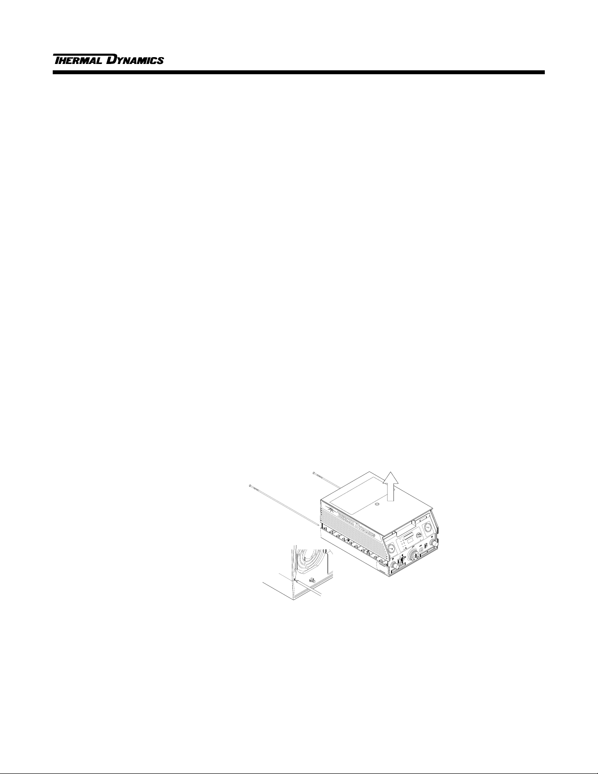
Opening the Enclosure
The upper half of the control module enclosure must be removed to install the wire harness and SC-6 Voltage
Divider PC Board (Refer to Figure 1):
Control Module Assembly. The
1. Unscrew and remove the two module assembly pins which secure the upper control module enclosure to
the lower.
2. Lift the upper enclosure from the control module.
Lift the upper
Remove the two module
assembly pins from rear panel
(see pin removal detail below).
Use a flat blade screwdriver
to pry the pin outward from
the top until threads engage,
then use a phillips head
screwdriver to fully
remove the pin
Pin Removal Detail (Reverse View)
enclosure from
the control module.
CURRENT
PLASMA
GAS
A
STAK PAK
CSD
AC
TEMP
STANDARD
AMPS
WORK
GAS
DC
TORCH
LATCH
PILOT
RUN
SECONDARY/
PURGE
SINGLE GAS
ON
SET
CONTROL
MODULE
CM 6030
Figure 1 - Opening the Control Module Enclosure
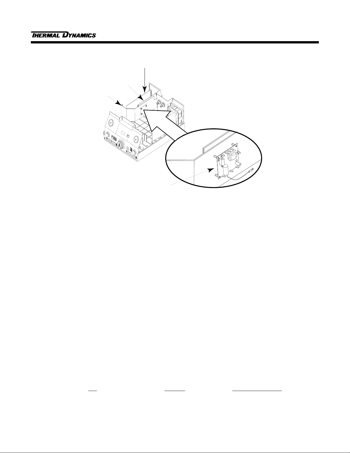
Installing SC-6 Voltage Divider PCB Assembly
Refer to Figure 2 and install the SC-6 Voltage Divider PCB Assembly as follows:
1
10/14/94
Page 2
SC-6 STANDOFF CONTROL INSTALLATION 0-2454
Analog PCB
Assembly
Divider Panel
Logic PCB
Assembly
SC-6 Voltage Divider
PCB Assembly
Figure 2 - Installing SC-6 Voltage Divider PCB Assembly
1. Locate and remove both the Analog and Logic PC Boards for the unit. Before removing any cabling be
sure to note which cable goes where.
2. Locate the divider panel inside the control module.
3. Locate the SC-6 Voltage Divider PCB Assembly included with the SC-6 componentds.
4. Install the PCB assembly onto the divider panel using the screws and standoffs supplied, using the four
existing holes.
5. Reinstall the Analog and Logic PC Boards making sure that all cables are reinstalled properly.
J24 Wire Harness Installation
NOTE
This wire harness is connected to the SC-6 Voltage Divider PCB at the factory.
The information is supplied to insure proper installation.
Install the J24 Wire Harness Assembly as follows (refer to Figures 3 and 4):
1. Connect the four wires from the wire harness cable to the Voltage Divider PCB per the following:
Wire SC-6 Voltage
Pin Number Divider Connection
14 95 Logic +
11 94 Logic 12 93 Signal +
8 96 Signal -
2
Page 3

SC-6 STANDOFF CONTROL INSTALLATION 0-2454
Signal -
(96)
Signal +
(93)
Logic +
(95)
J24
Receptacle
Logic -
(94)
SC-6 Voltage Divider
PC Board
Figure 3 - J24 Wiring Harness Assembly
2. Route the wire harness to the rear of the voltage selection plugs. and through the notch in the divider panel.
3. Continue routing the wire harness around the end of the Analog PCB Assembly to the J24 receptacle
location in the rear panel.
4. Using a punch, knock out the rear panel mounting hole for the J24 receptacle and install the receptacle on
the other end of the wire harness to the rear panel with the hardware provided.
MUM PRESSURE
J22
HIGH FLOW WATER SHIELD
J24
STANDOFF CONTROL
J11
REMOTE CONTROL
Figure 4 - Installation of J24
3
J24 Connector
At Rear Panel
Of Control Module
Page 4

SC-6 STANDOFF CONTROL INSTALLATION 0-2454
Pilot Wire Harness Installation
NOTE
This wire harness is connected to the SC-6 Voltage Divider PCB at the factory.
The information is supplied to insure proper installation.
Install the Pilot Wire Harness Assembly as follows (refer to Figures 5 and 6):
1. Connect the five wires from the wire harness cable to the SC-6 Voltage Divider PCB Assembly per the
following:
Wire SC-6 Voltage
Pin Number Divider Connection
1 57 Pilot Arc
3 56 P.S. +
7 54 P.S. 2 52 120 VAC
8 110 120 VAC
SC-6 Voltage Divider
PC Board
P.S. -
(54)
Figure 5 - Pilot Wire Harness Assembly
120 VAC
(52)
P.S. +
(56)
120 VAC
(110)
Connector
to Pilot PCB
(J8)
Pilot Arc
(57)
4
Page 5

SC-6 STANDOFF CONTROL INSTALLATION 0-2454
2. Connect the plug on the Wire Harness Assembly to J8 on the Pilot PCB Assembly.
J8
Pilot Wire
Harness
Connector
Figure 6 - Connection to Pilot PCB
Grounding Wir e Installation
The ground wire supplied with the SC-6 must be modified with a longer wire. Refer to Figure 7 and install the
wire as follows:
1. Cut the end off the ground wire soldered to the SC-6 Voltage Divider PCB Assembly.
2. Strip the end of the wire.
3. Connect the extra length of ground wire to this stripped wire with the supplied inline splice.
4. Connect the loose end of this extended ground wire to the primary ground stud of the control module.
WARNING
Do not attach the ground wire to the Voltage Divider Panel.
Insert wire into terminal block
and tighten set screw
L-3
L-2
GND
L-1
Figure 7 - Ground Wire Installation
Reinstall the enclosure cover by reversing the steps in “Opening The Enclosure” above.
®
This completes the installation of the components inside the STAK PAK
Control Module.
5
 Loading...