

Page 1
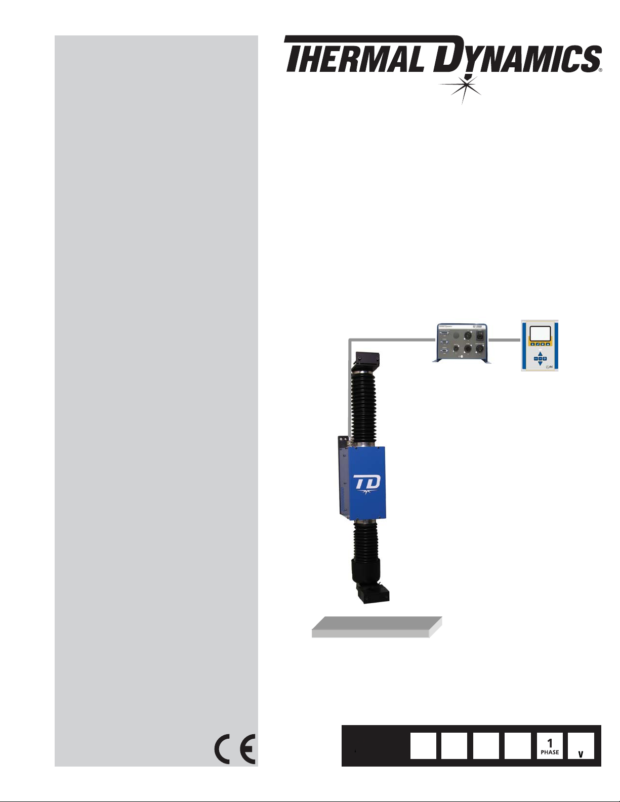
SC-3000
PRECISION TORCH
HEIGHT CONTROL
Operating Manual
Rev. AC Date: February 4, 2010 Manual # 0-5100
Operating Features:
PRECISION
PLASMA
12kg
26.4 lb.
CAPACITY
220mm
8.66in
STROKE
Art # A-08652
TACTILE
IHS
115230
Page 2

WE APPRECIATE YOUR BUSINESS!
Congratulations on your new Thermal Dynamics product. We are
proud to have you as our customer and will strive to provide you
with the best service and reliability in the industry. This product is
backed by our extensive warranty and world-wide service network.
To locate your nearest distributor or service agency call 1-800-4261888, or visit us on the web at www.thermal-dynamics.com.
This Operating Manual has been designed to instruct you on the
correct use and operation of your Thermal Dynamics product. Your
satisfaction with this product and its safe operation is our ultimate
concern. Therefore please take the time to read the entire manual,
especially the Safety Precautions. They will help you to avoid potential hazards that may exist when working with this product.
YOU ARE IN GOOD COMPANY!
The Brand of Choice for Contractors and Fabricators
Worldwide.
Thermal Dynamics is a Global Brand of manual and automation
Plasma Cutting Products for Thermadyne Industries Inc.
We distinguish ourselves from our competition through marketleading, dependable products that have stood the test of time.
We pride ourselves on technical innovation, competitive prices,
excellent delivery, superior customer service and technical support,
together with excellence in sales and marketing expertise.
Above all, we are committed to developing technologically advanced products to achieve a safer working environment within
the welding industry.
Page 3

!
WARNINGS
Read and understand this entire Manual and your employer’s safety practices before installing, operating, or servicing the equipment.
While the information contained in this Manual represents the Manufacturer's best judgement, the
Manufacturer assumes no liability for its use.
Precision Torch Height Control
SC-3000™
Operating Manual Number 0-5100
Published by:
Thermal Dynamics Corporation
82 Benning Street
West Lebanon, New Hampshire, USA 03784
(603) 298-5711
www.thermal-dynamics.com
Copyright 2009, 2010 by
Thermadyne Corporation
All rights reserved.
Reproduction of this work, in whole or in part, without written permission of the
publisher is prohibited.
The publisher does not assume and hereby disclaims any liability to any party for any
loss or damage caused by any error or omission in this Manual, whether such error
results from negligence, accident, or any other cause.
Printed in the United States of America
Original Publication Date: January 9, 2009
Revision Date: February 4, 2010
Record the following information for Warranty purposes:
Where Purchased:_______________________________ ________________
Purchase Date:__________________________________ ________________
Power Supply Serial #:___________________________ ________________
Torch Serial #:___________________________________ ________________
i
Page 4

This Page Intentionally Blank
Page 5

TABLE OF CONTENTS
SECTION 1:GENERAL INFORMATION ...................................................................................1-1
1.01 Notes, Cautions and Warnings ...................................................................1-1
1.02 Important Safety Precautions .....................................................................1-1
1.03 Publications.................................................................................................1-2
1.04 Note, Attention et Avertissement ................................................................1-3
1.05 Precautions De Securite Importantes .........................................................1-3
1.06 Documents De Reference ...........................................................................1-5
1.07 Declaration of Conformity ...........................................................................1-6
1.08 Statement of Warranty ................................................................................1-7
SECTION 2 SYSTEM:INTRODUCTION .................................................................................2-1
2.01 How To Use This Manual ............................................................................2-1
2.02 Equipment Identification .............................................................................2-1
2.03 Receipt Of Equipment .................................................................................2-1
2.04 System Specifications .................................................................................2-2
2.05 System Componants ..................................................................................2-3
2.06 Application and System Description ...........................................................2-7
SECTION 3 SYSTEM: INSTALLATION ...................................................................................3-1
3.01 Unpacking ................................................................................................... 3-1
3.02 Handling Options ........................................................................................3-1
3.03 System Layout ............................................................................................3-2
3.04 Installation ...................................................................................................3-4
3.05 Checking of Grounding .............................................................................3-18
SECTION 4 SYSTEM: OPERATION ........................................................................................ 4-1
4.01 Requirements and Check List for first Start-up ........................................... 4-1
4.02 Power Up ....................................................................................................4-1
4.03 OPERATOR TERMINAL Menu-Overview ...................................................4-3
4.04 OPERATOR TERMINAL SETTINGS ..........................................................4-4
4.05 SIGNAL FLOW DURING PLASMA CUTTING ............................................4-9
4.06 SC 3000 Operation Sequence .................................................................... 4-9
4.07 LOSS OF PLASMA ARC ..........................................................................4-12
4.08 DETECTION OF KERFS AND EDGES DURING CUTTING ....................4-12
4.09 SCRAP CUTTING ....................................................................................4-14
4.10 PROCEDURE WITH GAS PRE-FLOW ....................................................4-16
4.11 SC 3000 Torch Height Control (THC) Modes of Operation .......................4-18
4.12 Parameter Setting ..................................................................................... 4-19
SECTION 5 SYSTEM:SERVICE ..............................................................................................5-1
5.01 General Maintenance .................................................................................5-1
5.02 Troubleshooting ...........................................................................................5-2
SECTION 6:PARTS LISTS ....................................................................................................... 6-1
6.01 Introduction .................................................................................................6-1
6.02 Ordering Information ................................................................................... 6-1
6.03 Replacement Parts ....................................................................................6-2
Page 6

TABLE OF CONTENTS
APPENDIX 1: DEFINITIONS .................................................................................................. A-1
APPENDIX 2: GROUNDING A CUTTING MACHINE ............................................................ A-2
APPENDIX 3: POWER SUPPLY ............................................................................................ A-4
APPENDIX 4: INTERFACE .................................................................................................... A-5
APPENDIX 5: OPERATOR TERMINAL-REMOTE ................................................................. A-7
APPENDIX 6: CNC CONNECTIONS TO OTHER CONTROLLERS ..................................... A-8
APPENDIX 7: CONTROLLER SCHEMATIC ........................................................................ A-12
GLOBAL CUSTOMER SERVICE CONTACT INFORMATION ......................... Inside Rear Cover
Page 7
SC 3000
!
SECTION 1:
GENERAL INFORMATION
1.01 Notes, Cautions and Warnings
Throughout this manual, notes, cautions, and warnings are used to
highlight important information. These highlights are categorized as
follows:
NOTE
An operation, procedure, or background information
which requires additional emphasis or is helpful in efficient operation of the system.
CAUTION
A procedure which, if not properly followed, may cause
damage to the equipment.
WARNING
A procedure which, if not properly followed, may cause
injury to the operator or others in the operating area.
1.02 Important Safety Precautions
• The kinds of fumes and gases from the plasma arc depend on
the kind of metal being used, coatings on the metal, and the
different processes. You must be very careful when cutting
or welding any metals which may contain one or more of the
following:
Antimony Chromium Mercury
Arsenic Cobalt Nickel
Barium Copper Selenium
Beryllium Lead Silver
Cadmium Manganese Vanadium
• Always read the Material Safety Data Sheets (MSDS) that should
be supplied with the material you are using. These MSDSs
will give you the information regarding the kind and amount of
fumes and gases that may be dangerous to your health.
• For information on how to test for fumes and gases in your
workplace, refer to item 1 in Subsection 1.03, Publications in
this manual.
• Use special equipment, such as water or down draft cutting
tables, to capture fumes and gases.
• Do not use the plasma torch in an area where combustible or
explosive gases or materials are located.
• Phosgene, a toxic gas, is generated from the vapors of chlorinated solvents and cleansers. Remove all sources of these
vapors.
• This product, when used for welding or cutting, produces
fumes or gases which contain chemicals known to the State
of California to cause birth defects and, in some cases, cancer.
(California Health & Safety Code Sec. 25249.5 et seq.)
WARNINGS
OPERATION AND MAINTENANCE OF PLASMA ARC
EQUIPMENT CAN BE DANGEROUS AND HAZARDOUS
TO YOUR HEALTH.
Plasma arc cutting produces intense electric and
magnetic emissions that may interfere with the proper
function of cardiac pacemakers, hearing aids, or other
electronic health equipment. Persons who work near
plasma arc cutting applications should consult their
medical health professional and the manufacturer of
the health equipment to determine whether a hazard
exists.
To prevent possible injury, read, understand and follow
all warnings, safety precautions and instructions before
using the equipment. Call 1-603-298-5711 or your local
distributor if you have any questions.
GASES AND FUMES
Gases and fumes produced during the plasma cutting process can be
dangerous and hazardous to your health.
• Keep all fumes and gases from the breathing area. Keep your
head out of the welding fume plume.
• Use an air-supplied respirator if ventilation is not adequate to
remove all fumes and gases.
ELECTRIC SHOCK
Electric Shock can injure or kill. The plasma arc process uses and
produces high voltage electrical energy. This electric energy can cause
severe or fatal shock to the operator or others in the workplace.
• Never touch any parts that are electrically “live” or “hot.”
• Wear dry gloves and clothing. Insulate yourself from the work
piece or other parts of the welding circuit.
• Repair or replace all worn or damaged parts.
• Extra care must be taken when the workplace is moist or
damp.
• Install and maintain equipment according to NEC code, refer
to item 9 in Subsection 1.03, Publications.
• Disconnect power source before performing any service or
repairs.
• Read and follow all the instructions in the Operating Manual.
FIRE AND EXPLOSION
Fire and explosion can be caused by hot slag, sparks, or the plasma
arc.
• Be sure there is no combustible or flammable material in the
workplace. Any material that cannot be removed must be
protected.
• Ventilate all flammable or explosive vapors from the workplace.
Manual 0-5100 1-1 GENERAL INFORMATION
Page 8

SC 3000
• Do not cut or weld on containers that may have held combustibles.
• Provide a fire watch when working in an area where fire hazards
may exist.
• Hydrogen gas may be formed and trapped under aluminum
workpieces when they are cut underwater or while using a water
table. DO NOT cut aluminum alloys underwater or on a water
table unless the hydrogen gas can be eliminated or dissipated.
Trapped hydrogen gas that is ignited will cause an explosion.
NOISE
Noise can cause permanent hearing loss. Plasma arc processes can
cause noise levels to exceed safe limits. You must protect your ears
from loud noise to prevent permanent loss of hearing.
1.03 Publications
Refer to the following standards or their latest revisions for more
information:
1. OSHA, SAFETY AND HEALTH STANDARDS, 29CFR 1910,
obtainable from the Superintendent of Documents, U.S.
Government Printing Office, Washington, D.C. 20402
2. ANSI Standard Z49.1, SAFETY IN WELDING AND CUTTING,
obtainable from the American Welding Society, 550 N.W.
LeJeune Rd, Miami, FL 33126
3. NIOSH, SAFETY AND HEALTH IN ARC WELDING AND GAS
WELDING AND CUTTING, obtainable from the Superintendent
of Documents, U.S. Government Printing Office, Washington,
D.C. 20402
• To protect your hearing from loud noise, wear protective ear
plugs and/or ear muffs. Protect others in the workplace.
• Noise levels should be measured to be sure the decibels (sound)
do not exceed safe levels.
• For information on how to test for noise, see item 1 in Subsection 1.03, Publications, in this manual.
PLASMA ARC RAYS
Plasma Arc Rays can injure your eyes and burn your skin. The plasma
arc process produces very bright ultra violet and infra red light. These
arc rays will damage your eyes and burn your skin if you are not
properly protected.
• To protect your eyes, always wear a welding helmet or shield.
Also always wear safety glasses with side shields, goggles or
other protective eye wear.
• Wear welding gloves and suitable clothing to protect your skin
from the arc rays and sparks.
• Keep helmet and safety glasses in good condition. Replace
lenses when cracked, chipped or dirty.
• Protect others in the work area from the arc rays. Use protective
booths, screens or shields.
• Use the shade of lens as suggested in the following per ANSI/
ASC Z49.1:
Minimum Protective Suggested
Arc Current Shade No. Shade No.
Less Than 300* 8 9
300 - 400* 9 12
400 - 800* 10 14
* These values apply where the actual arc is clearly seen.
Experience has shown that lighter filters may be used
when the arc is hidden by the workpiece.
4. ANSI Standard Z87.1, SAFE PRACTICES FOR OCCUPATION
AND EDUCATIONAL EYE AND FACE PROTECTION, obtainable
from American National Standards Institute, 1430 Broadway,
New York, NY 10018
5. ANSI Standard Z41.1, STANDARD FOR MEN’S SAFETY-TOE
FOOTWEAR, obtainable from the American National Standards
Institute, 1430 Broadway, New York, NY 10018
6. ANSI Standard Z49.2, FIRE PREVENTION IN THE USE OF CUT-
TING AND WELDING PROCESSES, obtainable from American
National Standards Institute, 1430 Broadway, New York, NY
10018
7. AWS Standard A6.0, WELDING AND CUTTING CONTAIN-
ERS WHICH HAVE HELD COMBUSTIBLES, obtainable from
American Welding Society, 550 N.W. LeJeune Rd, Miami, FL
33126
8. NFPA Standard 51, OXYGEN-FUEL GAS SYSTEMS FOR
WELDING, CUTTING AND ALLIED PROCESSES, obtainable
from the National Fire Protection Association, Batterymarch
Park, Quincy, MA 02269
9. NFPA Standard 70, NATIONAL ELECTRICAL CODE, obtainable
from the National Fire Protection Association, Batterymarch
Park, Quincy, MA 02269
10. NFPA Standard 51B, CUTTING AND WELDING PROCESSES,
obtainable from the National Fire Protection Association,
Batterymarch Park, Quincy, MA 02269
11. CGA Pamphlet P-1, SAFE HANDLING OF COMPRESSED
GASES IN CYLINDERS, obtainable from the Compressed
Gas Association, 1235 Jefferson Davis Highway, Suite 501,
Arlington, VA 22202
12. CSA Standard W117.2, CODE FOR SAFETY IN WELDING
AND CUTTING, obtainable from the Canadian Standards Association, Standards Sales, 178 Rexdale Boulevard, Rexdale,
Ontario, Canada M9W 1R3
LEAD WARNING
This product contains chemicals, including lead, or otherwise produces
chemicals known to the State of California to cause cancer, birth defects
and other reproductive harm. Wash hands after handling. (California
Health & Safety Code § 25249.5 et seq.)
GENERAL INFORMATION 1-2 Manual 0-5100
from the National Welding Supply Association, 1900 Arch
Street, Philadelphia, PA 19103
13. NWSA booklet, WELDING SAFETY BIBLIOGRAPHY obtainable
Page 9
14. American Welding Society Standard AWSF4.1, RECOM-
!
MENDED SAFE PRACTICES FOR THE PREPARATION FOR
WELDING AND CUTTING OF CONTAINERS AND PIPING THAT
HAVE HELD HAZARDOUS SUBSTANCES, obtainable from the
American Welding Society, 550 N.W. LeJeune Rd, Miami, FL
33126
15. ANSI Standard Z88.2, PRACTICE FOR RESPIRATORY PROTECTION, obtainable from American National Standards
Institute, 1430 Broadway, New York, NY 10018
1.04 Note, Attention et Avertissement
Dans ce manuel, les mots “note,” “attention,” et “avertissement” sont
utilisés pour mettre en relief des informations à caractère important.
Ces mises en relief sont classifiées comme suit :
NOTE
Toute opération, procédure ou renseignement général
sur lequel il importe d’insister davantage ou qui contribue
à l’efficacité de fonctionnement du système.
ATTENTION
Toute procédure pouvant résulter l’endommagement
du matériel en cas de non-respect de la procédure en
question.
AVERTISSEMENT
Toute procédure pouvant provoquer des blessures de
l’opérateur ou des autres personnes se trouvant dans
la zone de travail en cas de non-respect de la procédure
en question.
1.05 Precautions De Securite Importantes
SC 3000
FUMÉE et GAZ
La fumée et les gaz produits par le procédé de jet de plasma peuvent
présenter des risques et des dangers de santé.
• Eloignez toute fumée et gaz de votre zone de respiration. Gardez
votre tête hors de la plume de fumée provenant du chalumeau.
• Utilisez un appareil respiratoire à alimentation en air si l’aération
fournie ne permet pas d’éliminer la fumée et les gaz.
• Les sortes de gaz et de fumée provenant de l’arc de plasma dépendent du genre de métal utilisé, des revêtements se trouvant sur le
métal et des différents procédés. Vous devez prendre soin lorsque
vous coupez ou soudez tout métal pouvant contenir un ou plusieurs
des éléments suivants:
antimoine cadmium mercure
argent chrome nickel
arsenic cobalt plomb
baryum cuivre sélénium
béryllium manganèse vanadium
• Lisez toujours les fiches de données sur la sécurité des matières
(sigle américain “MSDS”); celles-ci devraient être fournies avec le
matériel que vous utilisez. Les MSDS contiennent des renseignements quant à la quantité et la nature de la fumée et des gaz pouvant
poser des dangers de santé.
• Pour des informations sur la manière de tester la fumée et les gaz
de votre lieu de travail, consultez l’article 1 et les documents cités
à la page 5.
• Utilisez un équipement spécial tel que des tables de coupe à débit
d’eau ou à courant descendant pour capter la fumée et les gaz.
• N’utilisez pas le chalumeau au jet de plasma dans une zone où se
trouvent des matières ou des gaz combustibles ou explosifs.
• Le phosgène, un gaz toxique, est généré par la fumée provenant
des solvants et des produits de nettoyage chlorés. Eliminez toute
source de telle fumée.
• Ce produit, dans le procéder de soudage et de coupe, produit de
AVERTISSEMENTS
L’OPÉRATION ET LA MAINTENANCE DU MATÉRIEL
DE SOUDAGE À L’ARC AU JET DE PLASMA PEUVENT
PRÉSENTER DES RISQUES ET DES DANGERS DE
SANTÉ.
Coupant à l’arc au jet de plasma produit de l’énergie
électrique haute tension et des émissions magnétique qui
peuvent interférer la fonction propre d’un “pacemaker”
cardiaque, les appareils auditif, ou autre matériel de santé
electronique. Ceux qui travail près d’une application à
l’arc au jet de plasma devrait consulter leur membre professionel de médication et le manufacturier de matériel de
santé pour déterminer s’il existe des risques de santé.
Il faut communiquer aux opérateurs et au personnel
TOUS les dangers possibles. Afin d’éviter les blessures
possibles, lisez, comprenez et suivez tous les avertissements, toutes les précautions de sécurité et toutes les
consignes avant d’utiliser le matériel. Composez le +
603-298-5711 ou votre distributeur local si vous avez
des questions.
Manual 0-5100 1-3 GENERAL INFORMATION
la fumée ou des gaz pouvant contenir des éléments reconnu dans
L’état de la Californie, qui peuvent causer des défauts de naissance
et le cancer. (La sécurité de santé en Californie et la code sécurité
Sec. 25249.5 et seq.)
CHOC ELECTRIQUE
Les chocs électriques peuvent blesser ou même tuer. Le procédé au jet
de plasma requiert et produit de l’énergie électrique haute tension. Cette
énergie électrique peut produire des chocs graves, voire mortels, pour
l’opérateur et les autres personnes sur le lieu de travail.
• Ne touchez jamais une pièce “sous tension” ou “vive”; portez des
gants et des vêtements secs. Isolez-vous de la pièce de travail ou
des autres parties du circuit de soudage.
• Réparez ou remplacez toute pièce usée ou endommagée.
• Prenez des soins particuliers lorsque la zone de travail est humide
ou moite.
Page 10
SC 3000
• Montez et maintenez le matériel conformément au Code électrique
national des Etats-Unis. (Voir la page 5, article 9.)
• Débranchez l’alimentation électrique avant tout travail d’entretien
ou de réparation.
• Lisez et respectez toutes les consignes du Manuel de consignes.
INCENDIE ET EXPLOSION
Les incendies et les explosions peuvent résulter des scories chaudes,
des étincelles ou de l’arc de plasma. Le procédé à l’arc de plasma
produit du métal, des étincelles, des scories chaudes pouvant mettre
le feu aux matières combustibles ou provoquer l’explosion de fumées
inflammables.
• Utilisez la nuance de lentille qui est suggèrée dans le recommendation qui suivent ANSI/ASC Z49.1:
Nuance Minimum Nuance Suggerée
Courant Arc Protective Numéro Numéro
Moins de 300* 8 9
300 - 400* 9 12
400 - 800* 10 14
* Ces valeurs s’appliquent ou l’arc actuel est observé
clairement. L’experience a démontrer que les filtres
moins foncés peuvent être utilisés quand l’arc est caché
par moiceau de travail.
• Soyez certain qu’aucune matière combustible ou inflammable ne
se trouve sur le lieu de travail. Protégez toute telle matière qu’il
est impossible de retirer de la zone de travail.
• Procurez une bonne aération de toutes les fumées inflammables
ou explosives.
• Ne coupez pas et ne soudez pas les conteneurs ayant pu renfermer
des matières combustibles.
• Prévoyez une veille d’incendie lors de tout travail dans une zone
présentant des dangers d’incendie.
• Le gas hydrogène peut se former ou s’accumuler sous les pièces
de travail en aluminium lorsqu’elles sont coupées sous l’eau ou
sur une table d’eau. NE PAS couper les alliages en aluminium sous
l’eau ou sur une table d’eau à moins que le gas hydrogène peut
s’échapper ou se dissiper. Le gas hydrogène accumulé explosera
si enflammé.
RAYONS D’ARC DE PLASMA
Les rayons provenant de l’arc de plasma peuvent blesser vos yeux et
brûler votre peau. Le procédé à l’arc de plasma produit une lumière
infra-rouge et des rayons ultra-violets très forts. Ces rayons d’arc
nuiront à vos yeux et brûleront votre peau si vous ne vous protégez
pas correctement.
• Pour protéger vos yeux, portez toujours un casque ou un écran
de soudeur. Portez toujours des lunettes de sécurité munies de
parois latérales ou des lunettes de protection ou une autre sorte
de protection oculaire.
BRUIT
Le bruit peut provoquer une perte permanente de l’ouïe. Les procédés
de soudage à l’arc de plasma peuvent provoquer des niveaux sonores
supérieurs aux limites normalement acceptables. Vous dú4ez vous
protéger les oreilles contre les bruits forts afin d’éviter une perte
permanente de l’ouïe.
• Pour protéger votre ouïe contre les bruits forts, portez des tampons
protecteurs et/ou des protections auriculaires. Protégez également
les autres personnes se trouvant sur le lieu de travail.
• Il faut mesurer les niveaux sonores afin d’assurer que les décibels
(le bruit) ne dépassent pas les niveaux sûrs.
• Pour des renseignements sur la manière de tester le bruit, consultez
l’article 1, page 5.
PLOMB AVERTISSEMENT
Ce produit contient des produits chimiques, comme le plomb,
ou engendre des produits chimiques, reconnus par l’état de
Californie comme pouvant être à l’origine de cancer, de malformations fœtales ou d’autres problèmes de reproduction.
Il f a u t s e laver l e s mains a p r è s toute ma n i p u l a t i o n .
(Code de Californie de la sécurité et santé, paragraphe 25249.5 et
suivants)
• Portez des gants de soudeur et un vêtement protecteur approprié
pour protéger votre peau contre les étincelles et les rayons de
l’arc.
• Maintenez votre casque et vos lunettes de protection en bon état.
Remplacez toute lentille sale ou comportant fissure ou rognure.
• Protégez les autres personnes se trouvant sur la zone de travail
contre les rayons de l’arc en fournissant des cabines ou des écrans
de protection.
GENERAL INFORMATION 1-4 Manual 0-5100
Page 11

1.06 Documents De Reference
Consultez les normes suivantes ou les révisions les plus récentes ayant
été faites à celles-ci pour de plus amples renseignements :
1. OSHA, NORMES DE SÉCURITÉ DU TRAVAIL ET DE PROTECTION
DE LA SANTÉ, 29CFR 1910, disponible auprès du Superintendent
of Documents, U.S. Government Printing Office, Washington, D.C.
20402
2. Norme ANSI Z49.1, LA SÉCURITÉ DES OPÉRATIONS DE COUPE
ET DE SOUDAGE, disponible auprès de la Société Américaine de
Soudage (American Welding Society), 550 N.W. LeJeune Rd.,
Miami, FL 33126
3. NIOSH, LA SÉCURITÉ ET LA SANTÉ LORS DES OPÉRATIONS DE
COUPE ET DE SOUDAGE À L’ARC ET AU GAZ, disponible auprès
du Superintendent of Documents, U.S. Government Printing Office,
Washington, D.C. 20402
4. Norme ANSI Z87.1, PRATIQUES SURES POUR LA PROTECTION
DES YEUX ET DU VISAGE AU TRAVAIL ET DANS LES ECOLES,
disponible de l’Institut Américain des Normes Nationales (American National Standards Institute), 1430 Broadway, New York, NY
10018
5. Norme ANSI Z41.1, NORMES POUR LES CHAUSSURES PROTECTRICES, disponible auprès de l’American National Standards
Institute, 1430 Broadway, New York, NY 10018
SC 3000
14. Norme AWSF4.1 de l’Association Américaine de Soudage, RECOMMANDATIONS DE PRATIQUES SURES POUR LA PRÉPARATION À
LA COUPE ET AU SOUDAGE DE CONTENEURS ET TUYAUX AYANT
RENFERMÉ DES PRODUITS DANGEREUX , disponible auprès de
la American Welding Society, 550 N.W. LeJeune Rd., Miami, FL
33126
15. Norme ANSI Z88.2, PRATIQUES DE PROTECTION RESPIRATOIRE,
disponible auprès de l’American National Standards Institute, 1430
Broadway, New York, NY 10018
6. Norme ANSI Z49.2, PRÉVENTION DES INCENDIES LORS DE
L’EMPLOI DE PROCÉDÉS DE COUPE ET DE SOUDAGE, disponible
auprès de l’American National Standards Institute, 1430 Broadway,
New York, NY 10018
7. Norme A6.0 de l’Association Américaine du Soudage (AWS), LE
SOUDAGE ET LA COUPE DE CONTENEURS AYANT RENFERMÉ
DES PRODUITS COMBUSTIBLES, disponible auprès de la American
Welding Society, 550 N.W. LeJeune Rd., Miami, FL 33126
8. Norme 51 de l’Association Américaine pour la Protection contre les
Incendies (NFPA), LES SYSTEMES À GAZ AVEC ALIMENTATION
EN OXYGENE POUR LE SOUDAGE, LA COUPE ET LES PROCÉDÉS
ASSOCIÉS, disponible auprès de la National Fire Protection Association, Batterymarch Park, Quincy, MA 02269
9. Norme 70 de la NFPA, CODE ELECTRIQUE NATIONAL, disponible
auprès de la National Fire Protection Association, Batterymarch
Park, Quincy, MA 02269
10. Norme 51B de la NFPA, LES PROCÉDÉS DE COUPE ET DE SOUDAGE, disponible auprès de la National Fire Protection Association,
Batterymarch Park, Quincy, MA 02269
11. Brochure GCA P-1, LA MANIPULATION SANS RISQUE DES GAZ
COMPRIMÉS EN CYLINDRES, disponible auprès de l’Association
des Gaz Comprimés (Compressed Gas Association), 1235 Jefferson
Davis Highway, Suite 501, Arlington, VA 22202
12. Norme CSA W117.2, CODE DE SÉCURITÉ POUR LE SOUDAGE
ET LA COUPE, disponible auprès de l’Association des Normes
Canadiennes, Standards Sales, 178 Rexdale Boulevard, Rexdale,
Ontario, Canada, M9W 1R3
13. Livret NWSA, BIBLIOGRAPHIE SUR LA SÉCURITÉ DU SOUDAGE,
disponible auprès de l’Association Nationale de Fournitures de
Soudage (National Welding Supply Association), 1900 Arch Street,
Philadelphia, PA 19103
Manual 0-5100 1-5 GENERAL INFORMATION
Page 12

SC 3000
1.07 Declaration of Conformity
Manufacturer: Thermal Dynamics Corporation
Address: 82 Benning Street
West Lebanon, New Hampshire 03784
USA
The equipment described in this manual conforms to all applicable aspects and regulations of the ‘Low Voltage Directive’ (European Council Directive
73/23/EEC as amended by Council Directive 93/68/EEC) and to the National legislation for the enforcement of this Directive.
The equipment described in this manual conforms to all applicable aspects and regulations of the "EMC Directive" (European Council Directive 89/336/
EEC) and to the National legislation for the enforcement of this Directive.
Serial numbers are unique with each individual piece of equipment and details description, parts used to manufacture a unit and date of manufacture.
National Standard and Technical Specifications
The product is designed and manufactured to a number of standards and technical requirements. Among them are:
* CSA (Canadian Standards Association) standard C22.2 number 60 for Arc welding equipment.
* UL (Underwriters Laboratory) rating 94VO flammability testing for all printed-circuit boards used.
* CENELEC EN50199 EMC Product Standard for Arc Welding Equipment.
* ISO/IEC 60974-1 (BS 638-PT10) (EN 60 974-1) (EN50192) (EN50078) applicable to plasma cutting equipment and associated accessories.
* For environments with increased hazard of electrical shock, Power Supplies bearing the 'S' mark conform to EN50192 when used in conjunction with
hand torches with exposed cutting tips, if equipped with properly installed standoff guides.
* Extensive product design verification is conducted at the manufacturing facility as part of the routine design and manufacturing process. This is to
ensure the product is safe, when used according to instructions in this manual and related industry standards, and performs as specified. Rigorous
testing is incorporated into the manufacturing process to ensure the manufactured product meets or exceeds all design specifications.
Thermal Dynamics has been manufacturing products for more than 30 years, and will continue to achieve excellence in our area of manufacture.
Manufacturers responsible representative: Steve Ward
Thermadyne Europe
Europa Building
Chorley N Industrial Park
Chorley, Lancashire,
England PR6 7BX
Operations Director
GENERAL INFORMATION 1-6 Manual 0-5100
Page 13

SC 3000
1.08 Statement of Warranty
LIMITED WARRANTY: Subject to the terms and conditions established below, Thermal Dynamics® Corporation warrants to the original retail purchaser
that new Thermal Dynamics SC-3000™ Precision Height Control systems sold after the effective date of this warranty are free of defects in material
and workmanship. Should any failure to conform to this warranty appear within the applicable period stated below, Thermal Dynamics Corporation
shall, upon notification thereof and substantiation that the product has been stored operated and maintained in accordance with Thermal Dynamics’
specifications, instructions, recommendations and recognized industry practice, correct such defects by suitable repair or replacement.
This warranty is exclusive and in lieu of any warranty of merchantability or fitness for a particular purpose.
Thermal Dynamics will repair or replace, at its discretion, any warranted parts or components that fail due to defects in material or workmanship within the
time periods set out below. Thermal Dynamics Corporation must be notified within 30 days of any failure, at which time Thermal Dynamics Corporation
will provide instructions on the warranty procedures to be implemented.
Thermal Dynamics Corporation will honor warranty claims submitted within the warranty periods listed below. All warranty periods begin on the date
of sale of the product to the original retail customer or 1 year after sale to an authorized Thermal Dynamics Distributor.
LIMITED WARRANTY PERIOD
Product
SC-3000™
This warranty does not apply to:
1. Consumable Parts, such as tips, electrodes, shield cups, o - rings, starter cartridges, gas distributors, fuses, filters.
2. Equipment that has been modified by an unauthorized party, improperly installed, improperly operated or misused based upon industry
standards.
In the event of a claim under this warranty, the remedies shall be, at the discretion of Thermal Dynamics Corporation:
1. Repair of the defective product.
2. Replacement of the defective product.
3. Reimbursement of reasonable costs of repair when authorized in advance by Thermal Dynamics.
4. Payment of credit up to the purchase price less reasonable depreciation based on actual use.
These remedies may be authorized by Thermal Dynamics and are FOB West Lebanon, NH or an authorized Thermadyne service station. Product returned
for service is at the owner’s expense and no reimbursement of travel or transportation is authorized.
LIMITATION OF LIABILITY: Thermal Dynamics Corporation shall not under any circumstances be liable for special or consequential damages such
as, but not limited to, damage or loss of purchased or replacement goods or claims of customer of distributors (hereinafter “Purchaser”) for service
interruption. The remedies of the Purchaser set forth herein are exclusive and the liability of Thermal Dynamics with respect to any contract, or anything
done in connection therewith such as the performance or breach thereof, or from the manufacture, sale, delivery, resale, or use of the goods covered
by or furnished by Thermal Dynamics whether arising out of contract, negligence, strict tort, or under any warranty, or otherwise, shall not, except as
expressly provided herein, exceed the price of the goods upon which liability is based.
Control Interface and Terminal
(Parts and Labor)
1 Years 1 Year
Linear Drive
(Parts and Labor)
This warranty becomes invalid if replacement parts or accessories are used which may impair the safety or performance of any Thermal Dynamics
product.
This warranty is invalid if the Thermal Dynamics product is sold by non - authorized persons.
Effective January 5, 2009
Manual 0-5100 1-7 GENERAL INFORMATION
Page 14

SC 3000
This Page Intentionally Blank
GENERAL INFORMATION 1-8 Manual 0-5100
Page 15
SC-3000
!
SECTION 2 SYSTEM:
INTRODUCTION
2.01 How To Use This Manual
This Owner’s Manual applies to just specication
or part numbers listed on page i.
To ensure safe operation, read the entire manual,
including the chapter on safety instructions and
warnings.
Throughout this manual, the words WARNING,
CAUTION, and NOTE may appear. Pay
particular attention to the information provided
under these headings. These special annotations
are easily recognized as
follows:
WARNING
A WARNING gives information regarding
possible personal injury.
CAUTION
A CAUTION refers to possible equipment damage.
NOTE
2.02 Equipment Identification
The unit’s identication number (specication or
part number), model, and serial number usually
appear on a data tag attached to the rear panel.
Equipment which does not have a data tag such
as torch and cable assemblies are identied
only by the specication or part number
printed on loosely attached card or the shipping
container. Record these numbers on the bottom of
page 1 for future reference.
2.03 Receipt Of Equipment
When you receive the equipment, check it against
the invoice to make sure it is complete and inspect the equipment for possible damage due to
shipping. If there is any damage, notify the car-
rier immediately to le a claim. Furnish complete
information concerning damage claims or shipping errors to the location in your area listed in
the inside back cover of this manual.
Include all equipment identication numbers as
described above along with a full description of
the parts in error.
Move the equipment to the installation site before
un-crating the unit. Use care to avoid damaging
the equipment when using bars, hammers, etc., to
un-crate the unit.
A NOTE offers helpful information concerning
certain operating procedures.
Additional copies of this manual may be
purchased by contacting Thermadyne at the
address and phone number in your area listed
in the inside back cover of this manual. Include
the Owner’s Manual number and equipment
identication numbers.
Electronic copies of this manual can also be
downloaded at no charge in Acrobat PDF format
by going to the
Thermal Dynamics web site listed below and
clicking on Thermal Dynamics and then on the
Literature link:
http://www.thermal-dynamics.com
Manual 0-5100 2-1 INTRODUCTION
Page 16

SC-3000
2.04 System Specifications
Power supply 115/230 VAC ±10%
Current 2A/1A max.
Initial Position Finding -tactile
Clearance control in plasma mode by plasma arc voltage
Accuracy appr. ± 0.012" (± 0.3 mm)
Linear Drive Stroke = 8.3" (210 mm)
Speed = 3.1" / sec (80 mm / sec)
Load = 26.45 lbs (12 kg)
Collision protection built in.
INTRODUCTION 2-2 Manual 0-5100
Page 17
2.05 System Componants
Linear Drive
Operator
Terminal
SC-300 Interface
Enclosure
Linear Drive
Cable
Linear Drive
Power Cable
Operator Terminal
Cable
Power
Supply
CNC Cable
Art # A-08798_AB
OVERVIEW
SC-3000
Linear Drive contains the motor and control electronics for positioning the torch and controlling its
height.
Interface Enclosure provides the system power and the common connection point for all the systems
cables.
Remote Operator Terminal allow the operator to set and monitor all the parameters used to position and
control torch height.
Manual 0-5100 2-3 INTRODUCTION
Page 18
SC-3000
Art # A-08800
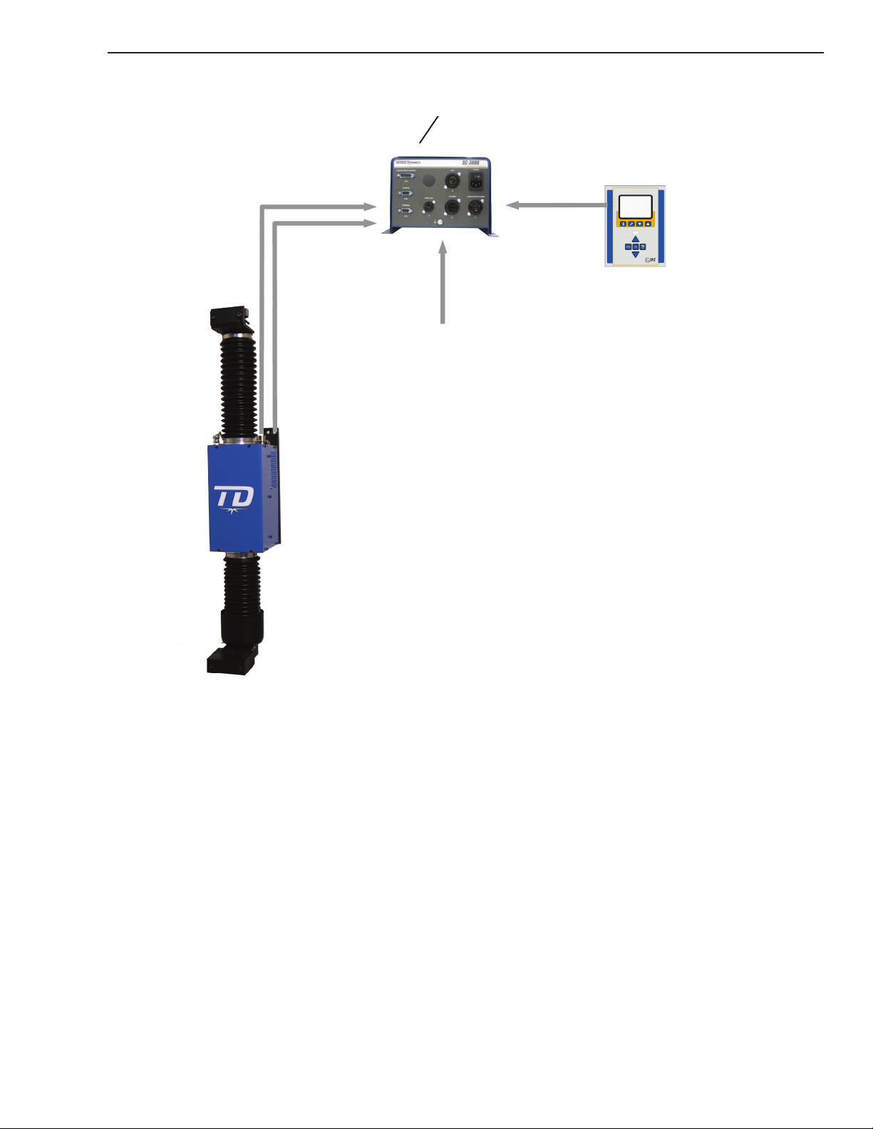
LINEAR DRIVE
Features
• Fast vertical drive for precise clearance control of plasma torches to metal sheets
• Integrated control
• Dust proof chamber protects rail and gear
• Built-in vertical collision protection
• 3-dimensional collision protection at the torch clamp
• Clamp for torch and leads
• High temperature proof bellows made of silicone rubber
• US Patent No. US 6,239,573 B1 / Euro Patent No. 0997801
General technical data
Motor 24 VDC / max. 6.5A
Power 100 W
Stroke 8.3" (210 mm)
Torch Clamp
for Torch Diameter 1.4"-2.1" (35-53 mm ) standard or
1.2"-1.4" (30-35 mm ) optional
Protective Earth Connector Screw M4
Weight 26.45 lbs. (12 kg )
Dimension of Housing approx. 4.5"x8.9"x6.3" (WxHxD)
(115x226x160 mm)
Dimensions overall 4.7"x2.8"x9.8" (WxHxD)
(approx.120x730x250 mm)
Features of versions
LINEAR DRIVE
Model SC-3000
TDC part no. 9-0404
Stroke 8.3" (210 mm)
Speed 3.1"/s (80 mm/s)
Load 26.45 lbs (12 kg)
Note:
The LINEAR DRIVE can only be used for vertical operation!
INTRODUCTION 2-4 Manual 0-5100
Page 19
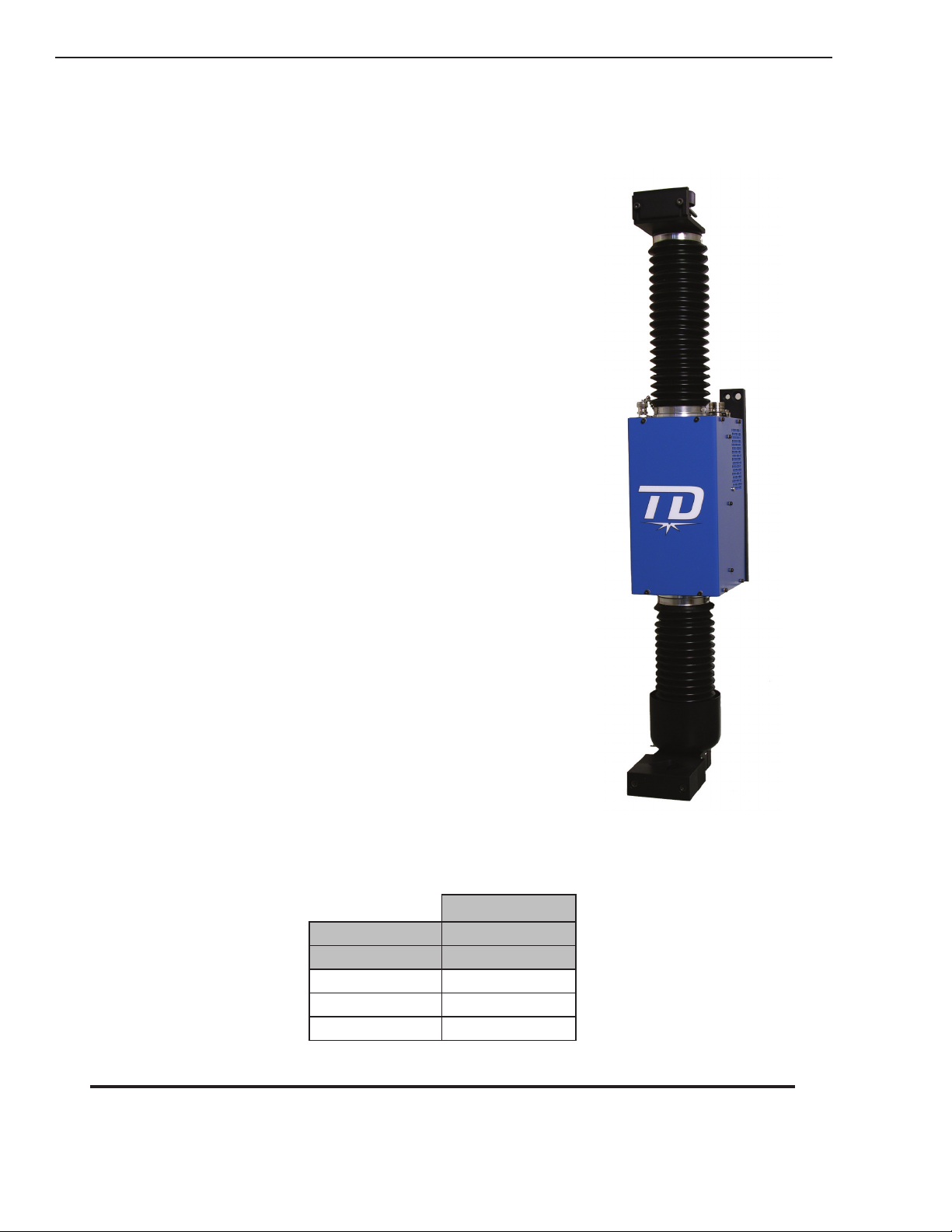
SC 3000 Interface Enclosure
Art # A-09098
Art # A-8938_AB
SC-3000
The Interface Enclosure is the central connection point for all the cables of the SC 3000 system. It contains:
• System power supply, 120 / 240 VAC to 24 VDC @ 6.5A (Appendix 4).
• Interface IHT 7250 Module providing communication between the Operator Terminal, the Plasma
Supply and the Linear Drive (Appendix 5).
• 9-0433 Control PCB providing system fuses, relays, selection switches for OK to Move and some
LEDs to assist troubleshooting.
Manual 0-5100 2-5 INTRODUCTION
Page 20
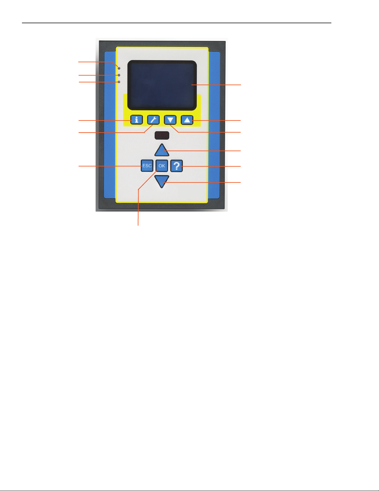
SC-3000
Art # A-08948_AB
Information menu
Fast settings
ESCAPE
Back to menu
Manual UP/Clear Error
Manual DOWN
Menu upwards
Help Menu
Me
nu downwards
Ready
Communication
Error
Display
OK
ENTER
Control Panel
Technical Information
Power 24 VDC ±10%, with integrated reverse voltage protection
Consumption 60 mA
Over Voltage protection 30 V
Graphic Display 128x64 pixel blue/white with LED backlight
Serial Interface RS485
Environment temperature 32°-122°F (0 to +50°C)
Relative Humidity 98% (non condensing)
Protection class IP10 EN60529/IEC529 for assembly into operator console
Dimensions 6.3"x4.8"x1.4" (160x120x35 mm)
Weight approx. 0.4 kg
SC-3000 part no. 9-0427
Connecting cables can be found in table / chapter Devices and spare parts.
INTRODUCTION 2-6 Manual 0-5100
Page 21
SC-3000
Art # A-8938_AB
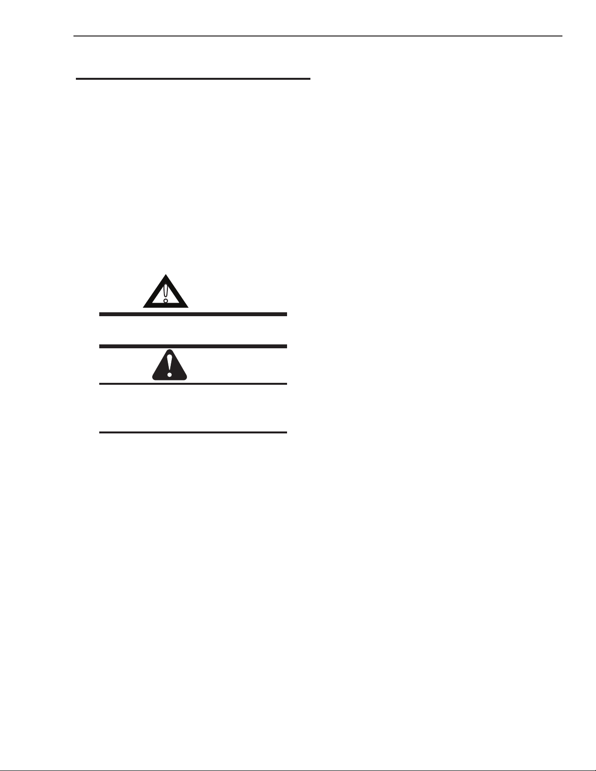
2.06 Application and System Description
The SC-3000 height control system enables a precise clearance control of plasma and oxyfuel torches
on cutting machines.
Using this height control system leads to high quality results when cutting with or without the inuence
of water.
The SC-3000 system automatically controls the distance between the plasma torch and the metal sheet.
Initial position finding of the work piece
Before the system starts cutting SC-3000 precisely detects the position of the work piece and nds the
pre-selected PIERCE HEIGHT (ignition height). This process is called initial position nding.
When cutting with plasma
• tactile, by softly touching the work piece
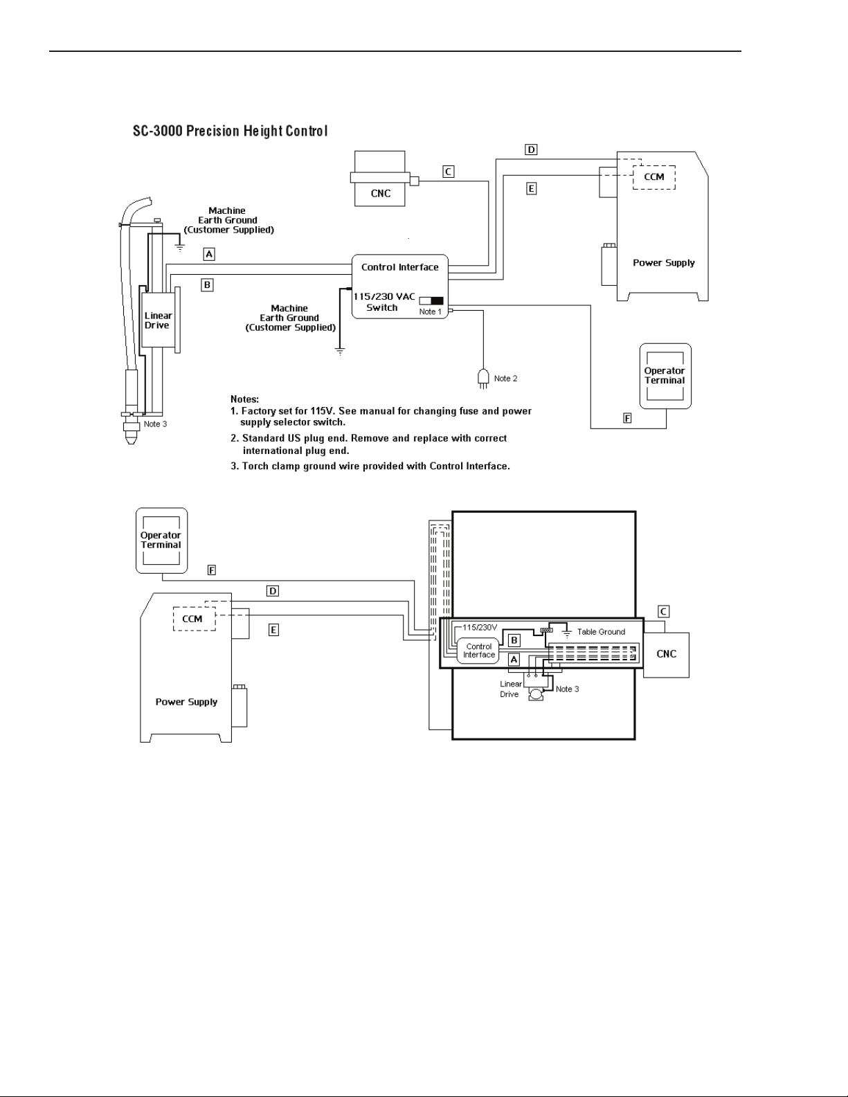
Explanation of the system and using the Interface Enclosure
SC3000 Torch Height Control system consists of a Linear Drive (Torch Lifter Station), a Remote
Operator Terminal and an Interface Enclosure plus various cables. The Interface Enclosure contains a
115V/230V to 24VDC power supply, an interface module and a PCB with fuses, relays, LEDs and set
up switches.
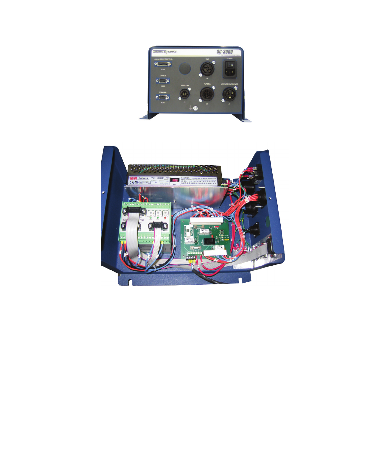
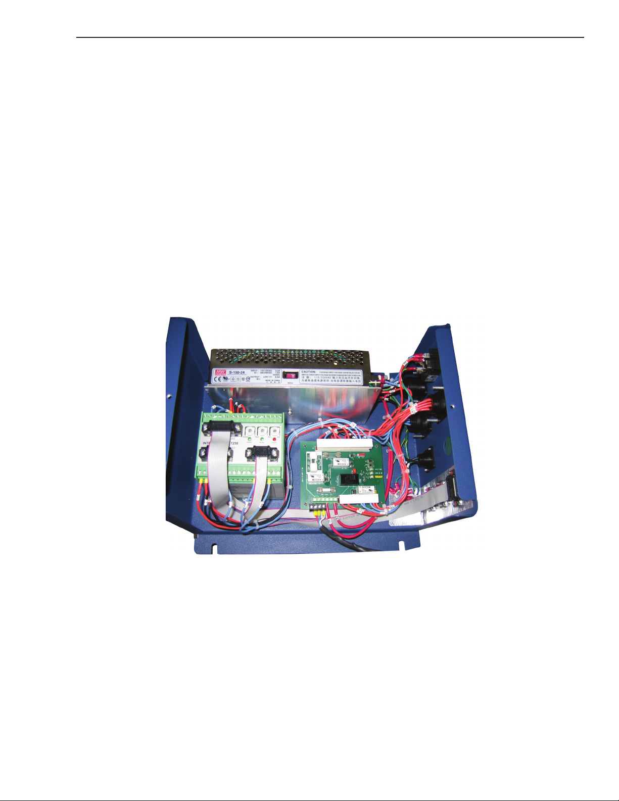
Inside the SC 3000 Enclosure 9-8145
Power Supply provides 24 VDC to operate the SC 3000. It is switch selectable for either 115 VAC or
230 VAC 50-60 Hz but failure to put the switch in the correct position can cause failure of the power
supply.
Interface Module
Interface Module is the green box next to the PCB. It has 3 rotary switches which allow selecting the
Address of the unit, The Baud Rate and the arc voltage input ratio. The Address and Baud Rate are used
for communication over the serial Cutbus. For now they should remain at their factory settings.
The Arc voltage may be set to accommodate different divided arc voltage ratios.
Manual 0-5100 2-7 INTRODUCTION
Page 22
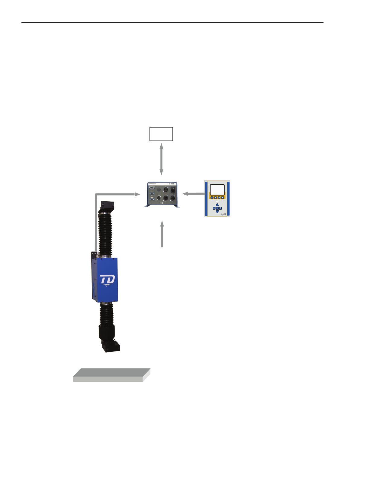
SC-3000
ARC voltage
from
plasma-source
OPERATOR
TERMINAL
Art # A-08799_AB
CNC
Movement of Torch
The vertical torch movement for initial position nding and clearance control is handled using the SC-
3000- LINEAR DRIVE.
The built in electronics in this LINEAR DRIVE processes all control signals from the CNC and the
plasma arc voltage for height control.
The Electronic Enclosure connects to the CNC-machine control, to the plasma sources for receiving the
plasma arc voltage and connects to the OPERATOR TERMINAL.
System overview
INTRODUCTION 2-8 Manual 0-5100
Page 23
SECTION 3 SYSTEM:
!
INSTALLATION
3.01 Unpacking
1. Use the packing lists to identify and account for each item.
2. Inspect each item for possible shipping damage. If damage is evident, contact your distributor
and / or shipping company before proceeding with the installation.
3. Record each componant's model and serial numbers, purchase date and vendor name, in the information block at the front of this manual.
3.02 Handling Options
Be sure unit is lifted and transported safely and securely.
WARNING
Do not touch live electrical parts.
Disconnect input power cord before moving unit.
SC-3000
FALLING EQUIPMENT can cause serious personal injury and can damage equipment.
• Only persons of adequate physical strength should lift the unit.
• Lift unit using two hands. Do not use straps for lifting.
• Use optional cart or similar device of adequate capacity to move unit.
• Place unit on a proper skid and secure in place before transporting with a fork lift or other vehicle.
• Do not grip or lift the Linear Drive by the belows.
Manual 0-5100 3-1 INSTALLATION
Page 24
SC-3000
Art # A-08904
3.03 System Layout
CONNECTING CABLES
INSTALLATION 3-2 Manual 0-5100
Page 25

SC-3000
KEY DESCRIPTION 15’ (5m) 25’
(7.62m)
Linear Drive Control 9-0406 9-0407
A
B
C
D
E
Linear Drive Power 9-0408 9-0409
* CNC Control 9-8312 9-8313 9-8315 9-8316
Preflow Control 9-0430 9-0431 9-0432 9-0433
Plasma Control 9-0426 9-0427 9-0428 9-0429
F
Operator Terminal 9-0416 9-0417
* CNC Control also available in 125’ (38m) -- 9-8317
Table 3-1 SC3000 Cables
30’ (10m) 50’
(15.24M)
65’ (20m) 75’
(22.86m)
100’
(30.48m)
User supplied ground cables required for Linear Drive and Interface Enclosure must be minimum of 8
AWG (8qmm). Larger is better.
Manual 0-5100 3-3 INSTALLATION
Page 26
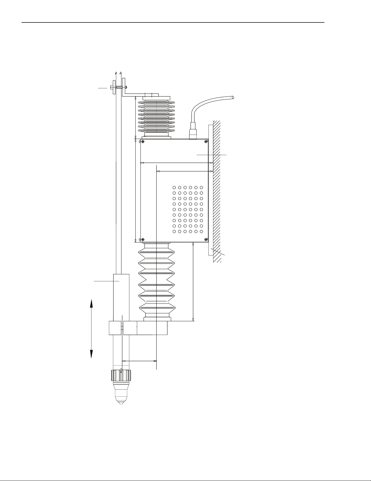
3.04 Installation
22 6mm - 8.9”
max. 360 / min.14 0mm
14.2” / 5.5”
min. 90 /max. 31 0mm
3.5” / 12.2”
160mm - 6.3”
120,4mm - 4.7”
76 mm
3”
Torch
Rear Mounting Plate
Cutting Machine
Linear Drive SC-3000
Hose Clamp
Art # A-08842
SIDE VIEW OF LINEAR DRIVE
View with plasma torch.
Dimensions in inches and milimeters
SC-3000
INSTALLATION 3-4 Manual 0-5100
Page 27

TOP VIEW LINEAR DRIVE SC-2343
Coax Cable
connector
for capacitiv
(Not Used)
Connector for Linear Drive
Control Cable
Connector for Linear
Drive Power Cable
PE
Grounding connector, to be
connected to machine ground
160mm
6.3”
120mm
4.7”
Art # A-08843
Electircal connectors
Dimensions inches and milimeters
SC-3000
CAUTION
Caution must be exercised to protect the bellows. Inspect for inward folds as these will cause premature wear.
Damaged bellows must be replaced as infiltrating dust can cause damage to the drive.
Manual 0-5100 3-5 INSTALLATION
Page 28

SC-3000
Front
Alternative
4 x M6 for rear
mounting
Art # A-08844
For vertical mounting at the cutting machine.
Optionally 4 screws M6 DIN 912 (drill hole dimensions 70x270 mm) or
4 screws M8 DIN 912 (drill hole dimensions 100x270 mm) can be used to x the Linear Drive from the
front.
INSTALLATION 3-6 Manual 0-5100
Page 29

SC-3000
Plasma Torch
Hoses, Cables
Check the sliding part of
LINEAR DRIVE:
Lift up here and
release it again.
The lifter slide must rest
lightly on the lower stop.
Adjust pressure with the
weight compensation knob.
A
djusting Knob for
Weight Compensation
LINEAR DRIVE - ADJUSTMENT OF WEIGHT COMPENSATION
This feature enables the adjustment of minimum vertical downward force when the nozzle
touches the work piece while getting the initial position.
The plasma torch must be mounted, the cable and the hose package must be clamped. The cable and
hoses outside must be exible so the sliding part of the LINEAR DRIVE is not hindered.
If the drive is hindered from moving, do not secure the cables and hoses in the clamp. If necessary use
an extended bracket.
1. Rotate the knob Weight Compensation clockwise until a slight lift up of the torch occurs. You
may hear a high pitched tone.
2. Rotate the knob counter clockwise until the tone stops and the lifter slide rests lightly on its
lower stop.
3. Check the weight compensation:
CAUTION!
To avoid excessive pressure between the torch and work piece, rotate knob “Weight Compensation”
counter clockwise only as far as necessary to lightly rest on the lower chock.
Manual 0-5100 3-7 INSTALLATION
Page 30

SC-3000
Push here
Ensure that deflection is not
blocked when adjusting screw has
been driven to hard.
Put in hex. wrench
#5mm
Hex. wrench #5mm
Collision
Protection Unit
Hose Clamp
Art # A-08907
LINEAR DRIVE - CHECK OF COLLISION PROTECTION
1. Push the torch clamp out of it’s normal position until the recess is left and release it again.
Check: The torch must return into correct vertical direction.
2. If the torch doesn’t safely return into the vertical direction then check that the hose does not hin-
dered the deection. If necessary correct the position of the hose.
However if the torch does not move exactly to the vertical direction then increase the deection
loading force:
3. Turn adjusting screw clockwise with a hex-wrench #5mm.
CAUTION!
Turn clockwise only as far as necessary to maintain sufficient deflection. The adjustment range of the vertical deflection force is from 30 to 120 N. If this is not maintained, the built-in collision switch doesn’t function and the
unit may be damaged in case of collision.
INSTALLATION 3-8 Manual 0-5100
Page 31

SC-3000
Pull out buckled folds
Art # A-08908_AB
CAUTION
Caution must be exercised to protect the bellows. Inspect for inward folds as these will cause premature wear.
Damaged bellows must be replaced as infiltrating dust can cause damage to the drive.
Manual 0-5100 3-9 INSTALLATION
Page 32

SC-3000
LINEAR DRIVE
PE
Grounding Terminal
Connector 6.3 mm/0.25 in. Faston
or terminal for M4 screw
Wire minimum 6 qmm/AWG8
Connect as short as possible
to machine ground
(less than 0.5 m).
LINEAR DRIVE
CONTROL CABLE
LINEAR DRIVE
POWER CABLE
Art # A-08909_AB
LINEAR DRIVE - ELECTRICAL CONNECTIONS
KEY DESCRIPTION 15’ (5m) 25’
A
B
INSTALLATION 3-10 Manual 0-5100
C
D
E
F
(7.62m)
30’ (10m) 50’
(15.24M)
65’ (20m) 75’
(22.86m)
(30.48m)
Linear Drive Control 9-0406 9-0407
Linear Drive Power 9-0408 9-0409
* CNC Control 9-8312 9-8313 9-8315 9-8316
Preflow Control 9-0430 9-0431 9-0432 9-0433
Plasma Control 9-0426 9-0427 9-0428 9-0429
Operator Terminal 9-0416 9-0417
* CNC Control also available in 125’ (38m) -- 9-8317
100’
Page 33

LINEAR DRIVE – GROUNDING OF TORCH CLAMP
Torch Clamp
Torch Clamp Grounding
Cable (Provided)
Grounding Cable
connect as short as possible
to machine ground
wire gauge min. 6 qmm/AWG8
(Customer Provided)
Art # A-08802_AB
This cable is required for safe operation !
The notes of grounding described in the Appendix must be observed for
proper usage.
Cable length: 0.6 m
Cable: 6 qmm/AWG 8, yellow/green lengthwise striped
2 connectors: Faston 6.3mm / 0.25 in.
SC-3000
CAUTION!
The length of the grounding cable up to the lower limit switch must not be so short as to hinder the movement of
the lifter.
Manual 0-5100 3-11 INSTALLATION
Page 34

SC-3000
24 VDC
DISABLE
(9)
OK to MOVE (0 VDC or Contact)
24VDC COMM
(15)
OK to MOVE +
24 VDC
24 VDC
OK TO MOVE (20VDC or C ontact)
OK to MOVE -
Plasma S tart
Co n t a ct cl o su r e
o r 2 0 V DC
(a p p l y 2 4V D C)
(13)
PLASMA START (24 VDC)
24 VDC
(12)
(a p p l y 2 4V D C)
24 VDC
(14)
J4 CNC
1
2
3
4
5
6
7
8
9
10
11
12
13
14
(10)
(11)
Height Control D is able 24VDC
24 VDC
24 VDC
(16)
OK
SW 1
SW1
2
1
3
5
4
6
+20 VDC
Ar t # A -0 909 1
Ar t # A -0 909 2
CNC OUTPUT
'
+
USER RELAY
'
VDC
Use DCV from CNC for relay coil or if us ing 24 VDC from SC 3000
must als o connect CNC common to SC 3000 24 VDC COMM
''
''
'
'
'
'
24 VDC @ J4-1
24 VDC @ J4-3 or J4- 10
START (J4- 4 ) or D ISABLE ( J4-11)
DIOD E
24 VDC COMM @ J4-2
Revers e E MF protection
Diode required for DC relay
Single ended.
CNC I/O Requirements for SC 3000 Electronic Enclosure
Plasma Start and Height Control Disable require +24 VDC to activate. If the CNC outputs can supply
+24V it can be used directly if it is referenced to the 24 VDC Common at J4-2.
If the CNC has relays with NO contacts the 24 VDC available from the SC 3000 at J4-1, 3 & 10 may
be routed through those relays to supply the required input signal.
For other CNC outputs such as single ended open collector user supplied relays will need to be added.
INSTALLATION 3-12 Manual 0-5100
Page 35

SC-3000
Discrete signal
inputs X301
Discrete signal
ouputs X305
Art # A-09093
OK to MOVE
OK to Move output from SC-3000 is factory set for relay contacts. SW1 on the PCB in the SC-3000
Electronic Enclosure can be set to supply 20-24 VDC through the OK to Move contacts. Total current
from all the 24 VDC should not exceed 500 ma. Too much current will blow F1, 1A fuse on the SC3000 Enclosure PCB.
Other Optional Functions
The SC-3000 Electronic Enclosure provides an access hole for user installed connections. Most of
these functions may be selected with the remote operators terminal but may be more convenient to have
separate controls for some of them.
IHT 7250 Interface Module (inside Electronic Enclosure)
Manual 0-5100 3-13 INSTALLATION
Page 36

SC-3000
COL
J3
1
2
3
4
5
6
Art # A-09099
Inputs X301
All of these require 24 VDC applied to activate. 24 VDC is available at output terminal X305-1 or one
of the +V terminals of the 24 VDC power supply.
X301-10 ------ Retract to ¾” (20 mm)
X301-11 ------ Retract to 2” (50 mm)
X301-12 ------ Scrap Cutting (bypasses nding height, set cutting height manually,
apply START.)
X301-14 ------ Manual Up
X301-15 ------ Manual Down
Outputs X305
Output signals are 20-24 VDC when active. Their mane purpose is to indicate to the CNC what the
status of the SC3000 is. These outputs could also be used to drive indicators lights for a visual status
indication.
They are:
X305-7 ----- Upper Limit. Arc voltage error has exceeded upper limit setting disabling
the height control until arc voltage drops below the limit. See explanation
of setting Upper Limit for more details.
X305-8 ----- Delay Time. SC3000 is not actively controlling height until Pierce Delay
and Control Delay has ended.
X305-10---- Control Active. SC3000 is actively controlling height.
X305-11 ---- Error. An error has occurred.
X305-14 ---- Reference/Retract Position. Torch has moved to it’s selected retract
position.
X305-16 ---- Reference Position. Torch has moved to it’s initial maximum retract
Position, possibly due to an error or a collision?
J3-4,5,6 ---- Collision is a special case where we have provided NO (normally open)
and NC (normally closed) relay contacts driven by the SC 3000’s built in collision sensor. Make con-
nections to J3 on the Interface PCB inside the Interface Enclosure.
For contact closure connect to J3-5 (comm.) and J3-6 (NO). For NC contact that opens with collision connect between J3-5 (comm.) and J3-4 (NC). Can also connect the J3-5 to +24 VDC (or other
voltage) if a voltage signal is require instead of contact closure.
INSTALLATION 3-14 Manual 0-5100
Page 37

R3
10k
R4 22k
R3
3,3k
C1
220n
R5 10k
74HCT14
GND
Input
Art # A-08946
Digital Input of Control Signals
R1
10k
PTC
+24V
T1
125 Ohm
R2 22 Ohm
Output
D1
D2
GND
Art # A-08947
SC-3000
Digital Output of Control Signals
Manual 0-5100 3-15 INSTALLATION
Page 38

SC-3000
Art # A-08919
Connection for
OPERATOR TERMINAL CA BLE
not used
not used
Attention when mounting the operator panel:
Connect PE-Terminal to PE-potential
of machine grounding.
Faston connector 6.3 mm / 0.25 in.
Wire gauge 0.75 qmm / 18 AWG
Art # A-08920_AB
OPTIONAL MOUNTING OF THE OPERATOR TERMINAL 9-0410
INSTALLATION 3-16 Manual 0-5100
Page 39

SC-3000
1 2 3 4 5 6
ON
█ █ █ █
OFF
█ █
Art # A-08921
OPERATOR TERMINAL CABLE
Art # A-09090
DEFAULT SETTING OF DIP-SWITCH
Do not change this setting!
OPERATOR TERMINAL - ELECTRICAL CONNECTION
The Operator Terminal Cable connects the Operator Terminal with the connector X201 at the Interface.
The power supply is provided by this cable as well.
Manual 0-5100 3-17 INSTALLATION
Page 40

SC-3000
3.05 Checking of Grounding
The following componants must be connected to
machine ground (PE) as described in the installation instructions to obtain a safe and reliable
operating system
• Control Interface 9-0405
• Linear Drive 9-0404
• Torch Clamp
INSTALLATION 3-18 Manual 0-5100
Page 41

SECTION 4 SYSTEM:
!
Both green LED’s should be on
Art # A-08923
OPERATION
WARNING!
Never put your hand under the torch.
4.01 Requirements and Check List for first Start-up
Step Instruction OK √
1 Are all cables and wires connected and locked properly?
2 Can the torch move in all directions without hitting anything?
Is the linear drive in vertical direction and mounted correctly?
3 Are the torch and the cable hose mounted correctly, weight
compensation and collision protection set properly?
4 Are all settings and signals from and to SC-3000 correct?
5 Are all grounding connections from the SC-3000 system
to the cutting machine and all cable shields connected to
machine ground as described in the instructions?
SC-3000
6 Is the power supply (+ 24V/6A) of the SC-3000 System
installed properly?
7 Is the resistance between ground and earth of the plasma
source less than 3 Ohm?
8 All shields of cables going to the plasma source should
not be connected at the plasma source. They must be
connected in the control cabinet with the shortest possible
connection to the machine ground.
4.02 Power Up
1. The Linear Drive moves the torch up to the upper reference position .
2. Operation check at the interface (Inside Electrical Enclosure).
3. Check operation at the Operator Terminal. After the power is switched on, an initialisation process runs for approx. 5 seconds. The green LED at the Operator Terminal is on.
Manual 0-5100 4-1 OPERATION
Page 42

SC-3000
Firmware Version
and Date
Active Keys
Status of
Initialisation
Art # A-08924
Art # A-08925
Art # A-08926
4. After initialisation, the main menu appears.
5. If the terminal displays ‘Communication Error’ the serial communication has failed. At the same
time the yellow LED will ash.
Check the power to Linear Drive.
Check the connection to Operator Terminal Cable.
OPERATION 4-2 Manual 0-5100
Page 43

4.03 OPERATOR TERMINAL Menu-Overview
Art # A-08948_AB
Information menu
Fast settings
ESCAPE
Back to menu
Manual UP/Clear Error
Manual DOWN
Menu upwards
Help Menu
Me
nu downwards
Ready
Communication
Error
Display
OK
ENTER
Operator Terminal
7260
Mode Select
Cutting Height
ARC Voltage
Capacitive Height
Device Info
Device Info
Serial No.
Hardware Version
Software Version
Status Info
Commands
Status
Corner ? Ref. Position ?
Upper Treshold ? Cap . Active ?
Control Active ? Cycle active ?
Real Voltage 122.5 V
Reset
Regulator Off
Threshold Off
Scrap Cut
Cut Height
Pierce Delay
Pierce Height
Control Delay
Ideal Voltage
Linear Drive
UP/DOWN
Help Text
?
ESC
Error Register
Automatic in the Display
Fault Weight Compensation ?
Fault ARC Voltage ?
Collision ?
Overload ?
Motor Polarity ?
Encoder ?
Error ?
OK
Error Reset
Press Button MAN UP
Parameter Cutheight
Dependent on choice of
control mode
Pierce Delay
Dynamic
Elevation Height
Retract Position
Pierce Height
Control Delay
Upper Threshold
Gas Pre-Flow
System Properties
Languages
English
German
System Parameters
Startup Time
OK
OK
OK
OK
Display
Cutting Height
Ideal Voltage
Real Voltage
i
OK
Main Menu
Commands and Status
Parameter Favorite
Cutting Height
for kerf and edge detection
Select mm / inch
End of Cut
Art # A-08927
SC-3000
Manual 0-5100 4-3 OPERATION
Page 44

SC-3000
Operator Terminal
Device Info
ESC
Parameter Cutheight
System Properties
Languages
English
German
System Parameter
OK
Display
Cutting Height
Ideal Voltage
Real Voltage
Main Menu
Control Mode
Art # A-08928_AB
ESC
OK
Device Info
Select MM/Inch
Unit Select
Unit: MM
Unit: Inch
System Properties
4.04 OPERATOR TERMINAL SETTINGS
Setting of Language and measurement units.
OPERATION 4-4 Manual 0-5100
Page 45

SC-3000
Operator Terminal
Mode Select
ARC Voltage
Device Info
ESC
Parameter Cutheight
System Properties
OK
Display
Cutting Height
Ideal Voltage
Real Voltage
Main Menu
Cutting Height Standard Setting
Art # A-08929
SETTING OF OPERATION MODES
There are two Operation Modes. For more detailed explanation of modes and their effects go to section
4.11.
1. ARC Voltage
Cutting height will be set via arc voltage setting.
This mode can be used for test cuts.
Example: 130.0 V
2. Cutting Height
Cutting height will be directly set in mm.
This is the standard operation mode.
Example: 2.5 mm
Manual 0-5100 4-5 OPERATION
Page 46

SC-3000
Mode Select
Device Info
ESC
Parameter Cutheight
Dependent on choice of
control mode
Pierce Delay
Dynamic
Elevation Height
Retract Position
Pierce Height
Control Delay
Upper Threshold
Gas Pre-Flow
System Properties
OK
Main Menu
Cutting Height
Select mm / inch
End of Cut
Operator Terminal
Display
Cutting Height
Ideal Voltage
Real Voltage
Time during piercing
Starts with signal START XY
Additional lifting during ignition
Distance during igntion
Reaction rate of clearance control
Blocking of clearance control when crossing kerfs
Height after end of cutting
Gas Pre-Flow starts with START INITIAL POSITION FINDING
Setting in percent of ideal arc voltage to detect end of cut
standard setting 85%
Height during cutting
Art # A-08930
CUTTING SETTINGS
For detailed explanation go to section 4.12.
OPERATION 4-6 Manual 0-5100
Page 47

COMMANDS AND STATUS
Operator Terminal
Status Info
Commands
Status
Corner ? Ref. Position ?
Kerf ?
Control active ?
Cycle active ?
Real Voltage 122.5 V
Reset
Regulator Off
Threshold Off
Scrap Cut
OK
Display
Cutting Height
Ideal Voltage
Real Voltage
i
OK
Commands and
Status
Linear Drive moves to upper reference
position
Clearance control is stopped
Initial position finding is stopped
Kerf and edge detection off
The Status shows the functions which are active during cutting.
Art # A-08931
SC-3000
Manual 0-5100 4-7 OPERATION
Page 48

SC-3000
Operator Terminal
Cut Height
Pierce Delay
Pierce Height
Control Delay
Display
Cutting Height
Ideal Voltage
Real Voltage
Parameter Favorite
Art # A-08932
Operator Terminal
Ideal Voltage
Linear Drive
UP/DOWN
Help Text
?
Display
Cutting Height
Ideal Voltage
Real Voltage
Art # A-08933
FAVORITE MENU
Using this menu, the main cutting parameters can be set quickly.
ADDITIONAL FUNCTIONS
OPERATION 4-8 Manual 0-5100
Page 49

4.05 SIGNAL FLOW DURING PLASMA CUTTING
From To Signal
CNC Initial Pos. Start
Plasma
Separate Ignition
Plasma
CNC Ok To Move
Delay Time
Control Active
Surface of work piece
Reference Position
Cutting Height
Plasma
Time / Track
Cutting On
Cutting Off
Pierce Height
Elevation Height
Start XY
Retract Position
Corner
1 2
3 4
5 6 State
Clearance
Art # A-08934_AB
SC-3000
SC-3000
SC-3000
SC-3000
SC-3000
SC-3000
SC-3000
SC-3000
OK PS
Plasma
CNC
SC-3000
4.06 SC 3000 Operation Sequence
Denitions:
THC
• Torch Height Control, in this case refers to the SC3000.
Initial Position Start
• Input where Start from CNC is applied to start THC’s height nding sequence.
Ready (Start XY)
• Input to THC for arc transferred signal from plasma (OK to Move).
Manual 0-5100 4-9 OPERATION
Page 50

SC-3000
Enable Ignition Plasma
• Originally intended to start the plasma, now used to start preow while nding height when that
feature is enabled (Operator Terminal Preow set to non-zero)
Separate Ignition Plasma
• Signal activates Start relay on PCB to supply isolated Start to plasma.
OK to Move-PS (plasma)
• Signal from plasma indicating arc transfer has occurred. Is routed directly to the THC and indirectly to CNC controller via OK to Move relay on PCB .
THC Pierce Delay
• Time (parameter set on the operator terminal) following arc transfer that torch remains at pierce or
elevated height.
OK to Move (THC)
• Signal from THC, active at end of THC pierce delay.
CNC Pierce Delay
• Dwell time after CNC receives OK to Move from THC or Plasma before CNC starts torch horizontal motion.
THC Preow time
• Setting on Operator Terminal (OT) used for preow during height nding. When the Operator Terminal Preow is set to zero plasma preow will not start until THC has positioned torch at pierce
height. Then gas ows for the full plasma preow time, default setting is 2 sec.
• Setting Preow to anything other than zero will activate Enable Ignition Plasma sending signal
to the plasma supply’s Preow On input (when cable is wired to TB2-3&4 of CCM) to start gas
ow at the same time that Initial Position Start is received from CNC. Gas ow starts immediately
and continues until Separate Ignition Plasma sends Start to plasma. If the time has already exceed
the plasma preow time (default is 2 sec) then pilot ignites immediately. If time has been less than
plasma preow time, plasma waits for the time remaining before igniting pilot.
THC Control delay
• Often called AVC delay, this is time starting when torch is moved to cut height until THC starts
controlling height to the sampled arc voltage.
OPERATION 4-10 Manual 0-5100
Page 51

Operation Sequence:
Assumes SW2, OK Source switch, on enclosure PCB set to “B” its factory default position.
1. CNC Start to THC Initial Position Start input.
a. If Preow on THC terminal is set to zero the Torch moves to nd plate then moves to pierce
height.
b. If Preow is not zero Enable Ignition Plasma becomes active starting preow via the plasma’s
Preow On input (Refer to section 4.10 for more details).Torch moves to nd the plate then
moves to pierce height.
2. Height found, torch at pierce height.
a. If Preow on THC terminal is set to zero the Start (Enable Ignition Plasma) to plasma imitates
the plasma Preow (default time 2 secs).. As Preow time ends pilot arc is ignited.
b. If Preow is not zero the Separate Ignition Plasma becomes active, sends Start to the Plasma.
The plasma whose preow was already started by Enable Ignition Plasma, ignites its Pilot arc
immediately if plasma’s preow timer has ended or as soon as it does end.
3. Arc Transfers, Plasma supply OK to Move on.
SC-3000
a. OK from plasma sent to THC Ready (Start XY) input. This moves torch to Elevate Height if
any set. This starts THC Pierce Delay.
NOTE
Torch remains at pierce or elevate height until THC Pierce Delay ends. This should be set equal to or longer than
CNC pierce delay. Longer allows torch to move away from the pierce slag before coming down to cut height.
b. At the same time, OK from plasma closes OK relay on SC3000 Enclosure PCB sending OK
to Move to the CNC.
• Motion delay for piercing is determined by CNC delay. In case CNC does not have ability
to set Pierce Delay then set SW2 to “A” and set desired pierce dwell time on THC Pierce
Delay. Torch will come down to cut height same time motion starts.
4. CNC Pierce dwell (delay) time ends.
a. CNC start moving torch horizontally.
5. THC Pierce Delay ends, torch moves down to Cut Height.
a. Control Delay time starts. THC is sampling the arc voltage, at end of control delay THC uses
the last stable sampled voltage as a reference to control height for rest of cut.
6. Corner
a. As the cutting table moves the torch through a corner or small radius the speed will be re-
duced. This causes the arc voltage to increase but we don’t want the THC to respond to this
change as it would move the torch into the plate. The CNC (cutting table controller) provides
a signal when it reduces speed which can be used to inhibit, disable or lock out the height control during these speed reductions.
Manual 0-5100 4-11 OPERATION
Page 52

SC-3000
7. End of Cut
a. The SC3000 requires 3 things happen to recognize the cut has ended.
• Start signal (Initial Position Start) from the CNC is removed.
• Cutting arc has ended (Ok to Move at Ready input is removed).
• Plasma Power supply output voltage reduces to a % of the normal cutting voltage set by
the End of Cut parameter (default 85%).
8. Retract
a. Following the end of cut the torch retracts to clear tipped up parts while moving to the next
cut position. The retract distance is set by the Retract Position parameter.
4.07 LOSS OF PLASMA ARC
It is possible that the plasma arc is lost during cutting process
The Linear Drive moves back up to the reference position as arc voltage is missing and the clearance
control cannot operate anymore.
4.08 DETECTION OF KERFS AND EDGES DURING CUTTING
This feature avoids that the plasma torch moves down into the kerf which has already been cut whilst
moving across.
If the adjustable Upper Threshold exceeds the limit during cutting, the clearance control will be disabled
when crossing kerfs.
Upper Threshold
When crossing a kerf or hole or going off the edge of the plate, arc voltage rises very rapidly. System
will respond to the rise in voltage by lowering the torch trying to keep voltage constant. To prevent this
an Upper Limit is set so when arc voltage exceeds the cutting voltage by the % specied by the Upper
Limit setting system stops trying to control height.
NOTE
For thicker metal which tend to be fairly flat and using lower cutting speeds the arc voltage doesn’t change very
rapidly except when crossing kerfs & holes so using a lower % will respond quicker, typically 5-10%. For higher
speeds on thinner or warped metal where normal cutting voltage changes more rapidly, use a higher number around
10-15% or even 20%.
OPERATION 4-12 Manual 0-5100
Page 53

Start
Crossing Kerf
Work piece
Threshold
e.g. 125V
ARC Voltage
e.g. 120V
Time / Track
Display at Operator Terminal in
the Status-Menu
Clearance Control on
Clearance Control off
Art # A-08935
SC-3000
Manual 0-5100 4-13 OPERATION
Page 54

SC-3000
From To Signal
CNC Initial Pos. Start
Plasma
Plasma Start
Start XY
Control Delay
Clearance Con.
Work piece
Reference Position
Cutting Height
Manual Down
Ignition
Time / Track
Cutting ON
Cutting OFF
Art # A-08936_AB
SC-3000
SC-3000
SC-3000
SC-3000
SC-3000
SC-3000
CNC
4.09 SCRAP CUTTING
The automatic nding of initial position is disabled when scrap cutting is activated.
The SC- 3000 system sets the following parameter automatically
• Pierce Height 0 mm
• Retract Position 0 mm
• Pierce Elevation 0 mm
• Cutting Height 0 mm
Procedure
• Select SCRAP CUTTING at Operator Terminal in the command menu.
• Move the torch to the start position manually.
• Move the torch to suitable cutting height manually.
• activate Initial Position Start.
OPERATION 4-14 Manual 0-5100
Page 55

This Page Intentionally Blank
SC-3000
Manual 0-5100 4-15 OPERATION
Page 56

SC-3000
4.10 PROCEDURE WITH GAS PRE-FLOW
Advantage:
The time of gas-pre-ow after reaching the piercing position is eliminated and the cutting cycle is shortened signicantly.
Preflow during Height Finding
To use Preow during Height Finding with an Ultracut or Autocut plasma system the 2 wires of the Preow Control cable from SC3000’s J5 Preow connector is connected into TB2-3 &4, polarity doesn’t
matter, in the Ultracut or Autocut CCM module.
Using the Operator Terminal from the main menu select the Cut Height parameter Gas Preow. Set to
a time other than zero, usually 2 sec same as the plasmas preow time. When the CNC sends Start to
the height control the SC3000 immediately applies the Preow On starting the plasma’s preow gas and
preow timer. Once the SC 3000 has positioned the torch to the initial Pierce Height position Start is
automatically sent to the plasma. If the preow timer has ended the arc is ignited immediately. It there
is any time remaining on the preow timer then that has to nish before pilot ignition and arc transfer
occurs but in any case the cycle time is reduced by the time it takes to nd height.
Typically you set the Gas Preow time equal to the preow time of the plasma supply however, at least
in the case of the Ultracut & Autocut, it doesn’t much matter, you can set it any time longer than zero.
If you don’t want the gases to come on during height nding then set Gas Preow to zero or don’t connect the Preow Control cable.
OPERATION 4-16 Manual 0-5100
Page 57

From
To Signal
CNC
Initial Pos. Start
Start XY
Control Delay
Clear. Contr. ON
Work piece
Reference Position
Cutting Height
Plasma
Time / Track
Cutting ON
Elevation Height
Pierce Height for Ignition
Gas Pre -flow
1 2
3
4
Art # A-08937_AB
SC-3000
SC-3000
SC-3000
SC-3000
SC-3000
CNC
SC-3000
Plasma
Start
SC-3000
Manual 0-5100 4-17 OPERATION
Page 58

SC-3000
4.11 SC 3000 Torch Height Control (THC) Modes of Operation
SC 3000 Torch Height Control (THC) Modes of Operation
Cutting Height Mode
Normal operating method is to use Cut Height Mode where desired cutting height is set directly in inch
or mm. This is somewhat different and easier to than most other height controls where you rst have to
determine the desired arc voltage. Refer to section 4.12 for details of setting the cutting parameters.
Arc Voltage Mode
Arc Voltage Mode
In the Arc Voltage Mode in addition to the cutting parameters used for Cut Height Mode you must
specify the desired Arc Voltage. Instead of the SC 3000 determining the correct arc voltage by sampling
it will use the voltage you enter as the reference. This requires you know the correct voltage for the
desired cutting height.
With Arc Voltage control the system still starts at Pierce Height, moves to Elevation Height at transfer,
goes to Cut Height (you must still enter a Cut Height) then after Height Control Pierce Delay and after
Control Delay the SC 3000 starts regulating height to the arc voltage you entered.
Cut Height Mode vs. Arc Voltage Mode—Advantages and disadvantages.
Cut Height Mode advantages:
• It is really the distance from the end of the torch to the work, not the arc voltage, that you want to
maintain constant. As torch consumables wear the arc voltage for a given height changes. With
Arc Voltage mode a smart operator will adjust the arc voltage setting to compensate. Many do not.
With Cut Height mode which takes a new sample each cut voltage change from consumable wear
is automatically compensated.
• You do not have perform test cuts to determine the correct arc voltage setting or rely on cut chart
numbers which are an average and may not be exactly right for your application.
Cut Height Mode disadvantages/Arc Voltage Advantages:
• The cut height the torch is positioned to and thus the sampled voltage is relative to the Pierce
Height which is found during the Find Height sequence. If that is not accurate, for example,
height was found on a piece of slag, then the height for the entire piece is wrong.
• With Arc Voltage Mode even if Pierce Height is off, as soon as Control Delay is nished it goes to
the height set by the arc voltage you entered assuming you got it right.
• If your CNC doesn’t allow setting a Pierce Delay so you have use Height Control Pierce Delay
(Correct use of Pierce Delay and Motion Delay for SW2 switch setting) then using Arc Voltage
Mode you can set the Cut Height somewhat higher than you want to cut at so that when the Height
Control Pierce Delay ends and the torch moves to Cut Height it is still above the piercing slag. Set
Control Delay just long enough that the torch moves past the slag the when THC starts controlling
the arc voltage torch will move to the correct cutting height.
Arc Voltage Mode disadvantages:
• Doesn’t compensate for consumable wear.
• Requires knowing and entering the correct voltage setting.
OPERATION 4-18 Manual 0-5100
Page 59

SC-3000
4.12 Parameter Setting
Pierce Height
• Initial height to which torch is positioned above the work piece during height nding process. Set
in increments of 0.004” (0-1.000”) or tenths of mm (0-25.0mm).
• Enter a height low enough for reliable transfer. Use Elevation Height to raise torch higher to complete pierce while minimizing blow back to the torch.
Note
Standard cut charts list Pierce Height as high as possible for height controls that don’t have Elevation Height. Finding height in a piece of slag can result in being too high to transfer. A lower Pierce Height can increase transfer
reliability when used with Elevation Height to raise torch above the piercing blowback immediately after transfer.
Feature is especially useful for piercing thicker material.
Pierce Delay (Height Control Setting, not to be confused with CNC controller setting to delay
motion)
• Sets Pierce Delay in tenths of seconds (0-9.9 sec)
• Pierce delay in the Height Control is time torch remains at Pierce Height or Elevation Height before moving to Cut Height.
• See "Correct use of THC Pierce Delay and CNC Motion Delay" later in this section for detailed
explanation of how to set Height Control Pierce Delay and CNC controller pierce or motion delay.
Cutting Height
• Selects desired cutting height in increments of 0.004” (0-0.800”) or tenths of mm. (0-20.0 mm.)
• Following pierce delay, THC moves torch to cut height, samples arc V. and at end of Control Delay
regulates to sampled arc V. (See Control Delay).
Elevation Height
• Distance to raise torch above Pierce Height. Set in increments of 0.004” (0-1.020”) or tenths of
mm. (0-25.5 mm)
• Immediately after arc transfer, torch is raised above the initial Pierce Height to Elevation Height.
Use Elevation Height to raise torch higher to complete the pierce while minimizing blow back to
the torch.
• Using Elevation Height allows setting a somewhat lower Pierce Height increasing the transfer reliability while further protecting the torch from blowback because it can immediately rise beyond
Pierce Height.
Manual 0-5100 4-19 OPERATION
Page 60

SC-3000
Control Delay
Often called AVC delay, this is time starting when torch is moved to cut height until THC starts controlling height to the sampled arc voltage.
a. Delay before system starts controlling height using arc voltage. Set in tenths of second (0-10.0
sec).
b. System nds surface of the metal then using an encoder for accuracy lifts the torch a measured
distance to Pierce Height. Following Pierce Delay torch is moved to Cut Height using information
from the encoder.
• Control Delay time starts. Torch remains at Cut Height during Control Delay. Near end of
Control Delay system samples arc voltage and saves it as a reference. At end of Control Delay
system start controlling height to maintain the actual arc voltage to equal the saved arc voltage
reference.
Hint: Set the delay long enough so cutting table is up to full cutting speed, torch has moved beyond
cutting slag and arc voltage has stabilized. But don’t set the delay so long that the distance to the metal
has changed from the initial cut height. To determine the correct setting, rst determine how far you
want the torch to move before turning on arc voltage control. Then considering the cutting speed, gure
how long it takes the torch to move that far.
Retract Position
• Sets the height the torch is raised (retracted) following end of a cut. Select in increments of 0.04”
(0- 4.0”) or 1 mm (0-100mm.) For full retract to the top position select 10.2” or 255mm. It may
not actually rise up 10.2 or 255 mm but that selection causes it to rise to the top.
• At end of a cut, before moving to the next cut, torch is normally retracted to clear any obstructions
such a part that tips up. Time is saved if a full retract is not required.
Hint: If cutting small parts that may tip up or thin metal that is likely to spring up, set for higher retract
to make sure the torch clears the cut piece. Use lesser amounts for larger pieces.
Upper Threshold
• Sets voltage upper limit as percent (0-20%) of operating arc voltage.
• When crossing a kerf or hole or going off the edge of the plate, arc voltage rises very rapidly.
System will respond to the rise in voltage by lowering the torch trying to keep voltage constant.
Without Upper Limit torch will be driven into the plate. When voltage exceeds Upper Limit setting, system stops trying to control height. Also refer to the Dynamic setting.
Hint: For thicker metal which tend to be fairly at and using lower cutting speeds the arc voltage
doesn’t change very rapidly except when crossing kerfs & holes so using a lower % will respond
quicker, typically 5-10%. For higher speeds on thinner or warped metal where normal cutting voltage
changes more rapidly, use a higher number around 10-15% or even 20%.
Dynamic
• Sets gain (response) of system (0-100). Factory setting of 40 is usually OK.
• With thicker metal and lower cutting speeds where a faster response is not needed a lower Dynamic setting in combination with a lower Upper Threshold %, can help prevent or limit torch diving
when crossing kerfs or holes or when the part or scrap drops out before nishing the cut.
• Very high speeds on very thin or highly warped metal may require increasing the Dynamic setting
to respond faster. Be careful to not go so high the torch overshoots and oscillates up and down.
Remember you will generally want to go back to 40 normal cutting.
OPERATION 4-20 Manual 0-5100
Page 61

SC-3000
Gas Preflow
Setting on Operator Terminal (OT) used for preow during height nding. (See "Preow during Height
Finding" later in this section).When the Operator Terminal Preow is set to zero plasma preow will
not start until THC has positioned torch at pierce height. Then gas ows for the full plasma preow
time, default setting is 2 sec.
Setting Preow to anything other than zero will activate Enable Ignition Plasma sending signal to the
plasma supply’s Preow On input (when cable is wired to TB2-3&4 of CCM) to start gas ow at the
same time that Initial Position Start is received from CNC. Gas ow starts immediately and continues
until Separate Ignition Plasma sends Start to plasma. If the time has already exceed the plasma preow
time (default is 2 sec) then pilot ignites immediately. If time has been less than plasma preow time,
plasma waits for the time remaining before igniting pilot.
• Set in tenths of a second (0-6.0 sec).
• Set to 0 disables the feature.
• To enable set time to equal the Plasma’s preow time.
• Used to speed up the cutting cycle time by starting preow gas at the same time as the torch is
coming down to nd height. Must connect separate Preow Control cable to plasma input to enable preow. See description of using Preow during Height Finding for details of how to use this
function.
Note
Not all plasma supplies have the inputs to use this feature.
End of Cut
• Set 0-100%.
• For the THC to detect that the cut is nished and retract the torch three things must happen. The
Start from the CNC (Initial Position Start) must be removed, the OK to Move from the plasma sup-
ply must go away indicating the cutting arc has stopped and the measured arc voltage must drop a
% below the voltage it was at while cutting. End of cut (0-100%) sets the % by which the voltage
has to reduce. Default setting is 85%. A lower % will add a small delay before retracting while the
plasma supply’s output voltage bleeds down. A higher percentage will shorten the delay.
Manual 0-5100 4-21 OPERATION
Page 62

SC-3000
Correct use of THC Pierce Delay and CNC Motion Delay.
As shipped from the factory the SC-3000 Height Control Interface PCB in the SC-3000 Interface Enclosure should have SW2 set to the “B” position. In this case the OK to Move signal from the plasma sup-
ply indicating the cutting are is present (arc has transferred) is sent to both the SC-3000 and the CNC at
the same time.
• The CNC pierce or motion delay should be set to the minimum time necessary for
the arc to fully pierce the metal.
• The THC Pierce Delay should be set at least as long as the CNC motion delay. Often it should be
longer. When you pierce, especially thicker metal, a ridge of slag and partially molten metal is
built up around the pierced hole. If you bring the torch down to cut height at the same time as motion starts you risk the torch contacting the slag which can damage the torch shield cap and perhaps
the orice. Best to add more Pierce Delay to the THC to clear the slag.
• If the CNC controller doesn’t have motion delay feature you can use the SC-3000 to delay motion.
• Set SW2 on the Height Control Interface PCB to the “A” then OK to Move to the CNC is also
delayed until end of Height Control Pierce Delay. In this case you will not be able to use the additional delay described above. Torch will come to cut height same time as motion starts and may
contact the slag if there is very much there.
Note
This may be a case where Arc Voltage Control Mode would work better. Refer to “Cut Height Mode vs. Arc Voltage
Mode—Advantages and disadvantages” section for explanation.
OPERATION 4-22 Manual 0-5100
Page 63

SC-3000
SECTION 5 SYSTEM:
SERVICE
5.01 General Maintenance
All components are maintenance free.
Cleaning housings:
• Switch power off!
• Dirt and grease may be removed using a cloth dampened with a mild detergent and water solution.
• To prevent damage avoid using chemicals that contain benzine, toluene, xylene, acetone, or similar volatile
solvents. Also avoid abrasive cleaners.
• Dry the surfaces carefully
Manual 0-5100 5-1 SERVICE
Page 64

SC-3000
Operator Terminal
Error Reset
Press Button MAN UP
Display
Cutting Height
Ideal Voltage
Real Voltage
Error Display
Automatic in the Display
Weight Compensation ?
Fault ARC Voltage ?
Collision ?
Overload ?
Motor Polarity ?
Encoder ?
Error ?
Art # A-08940
5.02 Troubleshooting
FAULT INDICATION AND RESET AT THE OPERATOR TERMINAL
In case of a fault the type of error will be displayed on the operator terminal. Press the Manual UP button to reset
after correcting the cause of the fault.
SERVICE 5-2 Manual 0-5100
Page 65

Fault Indication Effect Cause Correction
SC-3000
Weight compensation
ARC Voltage
Collision
Overload No Movement
Motor cables interchanged
Encoder
No initial position
finding
No finding of initial
position
Linear Drive moves
to upper reference
position
After power on the
torch lifter moves
downwards instead of
upwards.
Torch lifter moves to
limit switch
1.The hose of the torch pulls
upwards
2.Setting of weight
compensation too strong
3. Switch of initial position
finding
Arc voltage is missed at
Interface
Collision protection was
active Torch moved against
a barrier
1. Load too much 1. Check the load
2. Motor Amplifier faulty 2. Contact authorized service center for
3. Motor faulty 3. Contact authorized service center for
Motor cables interchanged Interchange motor connectors at pcb-board
Encoder or cable connection
faulty
1. Loosen the attachment of the hose
2. Turn knob at Linear Drive counter
clockwise.
Check of the weight compensation
described in chapter 4.
3. Contact authorized service center for
repair or replacement
Check the connection between plasma
source and Interface..
Eliminate the barrier.
Increase retract position if necessary.
repair or replacement
repair or replacement
Check the cables and connectors
Manual 0-5100 5-3 SERVICE
Page 66

SC-3000
This Page Intentionally Blank
SERVICE 5-4 Manual 0-5100
Page 67

SC-3000
SECTION 6:
PARTS LISTS
6.01 Introduction
A. Parts List Breakdown
The parts list provide a breakdown of all replaceable components. The parts lists are arranged as follows:
Section 6.03 Replacement Parts
NOTE
Parts listed without item numbers are not shown, but may be ordered by the catalog number shown.
B. Returns
If a product must be returned for service, contact your distributor. Materials returned without proper authorization will not be accepted.
6.02 Ordering Information
Order replacement parts by catalog number and complete description of the part or assembly, as listed in the parts
list for each type item. Also include the model and serial number of the power supply. Address all inquiries to
your authorized distributor.
Manual 0-5100 6-1 PARTS LIST
Page 68

SC-3000
6.03 Replacement Parts
Item # Qty Description Designation Catalog #
1 1 1.0A, 250V, 5mm, 216 series F2 8-4093
2 1 1.6A, 250V, 5mm, 234 series F1 (for 230 VAC) 8-4094
3 1 10.0A, 250V, 5mm, 215 series F3 9-0421
4 1 3.15A, 250V, 5mm, 234 series F1 (for 115 VAC) 9-0422
5 1 15 PIN Ribbon Cable 9-0425
6 1 9 PIN Ribbon Cable 9-0424
7 1 AC Power Cord, SC-11, SC-3000 9-0434
8 1 Control Interface, Electronics Enclosure Assembly Control Interface 9-8145
9 1 Fuse Cover, 5x20 PCB Fuse 9-0435
10 1 Height Control Enclosfure Base 9-8143
11 1 Height Control Enclosure Cover 9-8146
12 1 Operator Terminal 9-0410
13 1 Operator Terminal Mounting Bracket 9-0426
14 1 Interface IHT 7250 9-0405
15 1 Linear Drive Linear Drive 9-0404
16 1 Linear Drive Cable 30' (10m) A 9-0406
17 1 Linear Drive Cable 60' (20m) A 9-0407
18 1 Linear Drive Power Cable 30' (10m) B 9-0408
19 1 Linear Drive Power Cable 60' (20m) B 9-0409
20 1 Operator Terminal Cable 30' (10m) 9-0412
21 1 Operator Terminal Cable 15' (5m) 9-0411
22 1 Plasma Control Cable, 25' (7.6m) E 9-0426
23 1 Plasma Control Cable, 50' (15.2m) E 9-0427
24 1 Plasma Control Cable, 75' (22.8m) E 9-0428
25 1 Plasma Control Cable, 100' (30.5m) E 9-0429
26 1 Power Entry Module, 250V/10A 9-0423
27 1 Power Supply 9-0420
28 1 Preflow Control Cable, 25' (7.6m) D 9-0430
29 1 Preflow Control Cable, 50' (15.2m) D 9-0431
30 1 Preflow Control Cable, 75' (22.8m) D 9-0432
31 1 Preflow Control Cable, 100' (30.5m) D 9-0433
32 1 SC-3000 Control PCB 9-0419
33 1 Operator Terminal Assembly w/Terminal, 30' (10m) cable F 9-0417
34 1 Operator Terminal Assembly w/Terminal, 15' (5m) cable F 9-0416
35 1 Terminal Box Assembly 9-0427
36 1 CNC Control Cable 25' (7.6m) C 9-8312
37 1 CNC Control Cable 50' (15.2m) C 9-8313
38 1 CNC Control Cable 75' (22.8m) C 9-8315
39 1 CNC Control Cable 100' (30.5m) C 9-8316
40 1 CNC Control Cable 125' (38.0m) C 9-8317
PARTS LIST 6-2 Manual 0-5100
Page 69

SC-3000
Art # A-08904
Manual 0-5100 6-3 PARTS LIST
Page 70

SC-3000
This Page Intentionally Blank
PARTS LIST 6-4 Manual 0-5100
Page 71

SC-3000
APPENDIX 1: DEFINITIONS
THC
Torch Height Control, in this case refers to the SC3000.
Initial Position Start
Input where Start from CNC is applied to start THC’s height finding sequence.
Ready (Start XY)
Input to THC for arc transferred signal from plasma (OK to Move).
Enable Ignition Plasma
Originally intended to start the plasma, now used to start preflow while finding height when that feature is
enabled (Operator Terminal Preflow set to non-zero)
Separate Ignition Plasma
Signal activates Start relay on PCB to supply isolated Start to plasma.
OK to Move-PS(plasma)
Signal from plasma indicating arc transfer has occurred. Is routed directly to the THC and indirectly to CNC
controller via OK to Move relay on PCB .
THC Pierce Delay
Time (parameter set on the operator terminal) following arc transfer that torch remains at pierce or elevated
height.
OK to Move (THC)
Signal from THC, active at end of THC pierce delay.
CNC Pierce Delay
Dwell time after CNC receives OK to Move from THC or Plasma before CNC starts torch horizontal motion.
THC Preflow time
Setting on Operator Terminal (OT) used for preflow during height finding.
THC Control delay
Often called AVC delay, this is time starting when torch is moved to cut height until THC starts controlling
height to the sampled arc voltage.
Manual 0-5100 A-1 APPENDIX
Page 72

SC-3000
Star Point
Rail
Gantry
Torch
Lifter
Plasma source
Positive Plasma Voltage Output (Work Lead)
width of cable 1/0 AWG equivalent 50 qmm
Torch
width of cable 2/0 AWG
equivalent 70 qmm
on all 4 corners
Cutting Table
stranded wire 2/0 AWG
equivalent 70 qmm
Chassis of Machine Control
Ground Rod
width of cable 2/0 AWG
equivalen t 70 qmm
Rail
Art # A-08942_AB
APPENDIX 2: GROUNDING A CUTTING MACHINE
This information and recommendations which are described here should help to understand the importance of
correct machine grounding
Furthermore, all manufacturer installation instructions for cutting machines and plasma sources must be complied
with.
The accurate grounding of plasma cutting machines is one of the most important parts to ensure proper functioning. This prevents electromagnetic interference (EMI) problems which can disturb electrical devices and causes a
malfunction.
The aim is to achieve low electrical impedance from machine ground to earth ground.
This is described below.
NOTE
It implicates an improper use if no sufficient grounding is provided !
All components of the machine which need grounding must be connected to a single star point. Preferably this star
point is affixed at the cutting table and is connected to a ground rod by a suitable cable.
The distance to the star point should be less than 10' (3 meters). The resistance to ground should be less than 1
Ohms.
All metallic parts of the machine (servos, control console and height control components) must be connected to the
star point.
The four corners of the cutting table must be connected to the rail.
Example of a Cutting machine with a cutting current up to 150 A. The same cables used for welding can be used
as grounding cables.
Figure1: View from above (top view)
For a higher cutting current (more than 150 A) the width of cables should be increased to 4/0 AWG, equivalent
95 qmm.
APPENDIX A-2 Manual 0-5100
NOTE
Page 73

SC-3000
Plasma Source
plus
minus
Cutting Table
Return Path
Work piece
Star Point
Art # A-08942
Art # A-08943
PLASMA CURRENT RETURN PATH
The plasma cutting current is generated by the plasma source. The current flows from the negative terminal to the
torch, flows through the arc and the work piece to the cutting table.
From the star point the current flows back to the positive terminal of the plasma source.
To achieve a trouble-free operation, the impedance of the return path must be as small as possible.
For this purpose the proper electrical connection to the star point and to the plasma source have a great influence.
These electrical connections should be well maintained.
Figure 2
PROPER ELECTRICAL CONTACT
A proper electrical contact needs connections which are made with bare metal to metal contact. The connections
have to be very tight and should be protected against rust and corrosion.
Grounding connexion has to be connected to the machine ground in the shortest possible way.
Manual 0-5100 A-3 APPENDIX
Page 74

SC-3000
Input Voltage switch 230 VAC /115VAC
Supply Voltage Phase L
115VAC
protect externally with 3.2/1.6 AM
medium slow
Supply Voltage Phase N
115/230VAC
PE -Protective Earth Connector
+V
Output +24VDC / 6.5A
Protect externally with 10AT - slow
-V
Output 0V
Ground GND
Art # A-08944_AB
SC 3000 Interface Enclosure is preset to 115 VAC but replacement
power supplies will arrive set to 230 VAC.
APPENDIX 3: POWER SUPPLY
Features
• Stabilised power supply 24 VDC / 6.5 A;Suitable for operating a LINEAR DRIVE
• Operates with supply voltage 110/230 VAC / 50-60 Hz, selectable
Technical specifications
Dimensions 7.8"x4.3"x1.9" (199x110x50 mm) Length x Width x Height
Input AC Voltage 88-132VAC / 3.2A or 176-264VAC / 1.6A selectable
Frequency 50-60 Hz
Output DC Voltage 24VDC / 6,5A max.
Protection class IP 20 acc. EN60529/IEC529
Environment conditions 32°-104°F (0-40°C) / 20-90% relative humidity
Weight 1.76lbs. (0.8kg)
TDC part no. 9-0420
NOTE
Input voltage switch 230 VAC / 115 VAC. Factory default is 230 VAC
APPENDIX A-4 Manual 0-5100
Page 75

APPENDIX 4: INTERFACE
Art # A-08945
The Interface is the central signal distribution point for the SC-3000™ System.
SC-3000
Features
• Power supply 24 VDC / 0.5A
• Connector to LINEAR DRIVE
• Connector to OPERATOR TERMINAL
• Interface for CUTBUS® used for serial communication to CNC
• Discrete Input / Output terminals 24 VDC to connect SC-3000™ to CNC-machine control system 2x17-removable screw terminal strips. Special coding avoid mix-up.
• Integrated isolation amplifier for ARC voltage 0-10 VDC und 0-300 VDC from the plasma source
• 3 rotating switches to set
- Device address of Cutbus
- Baud rate for Cutbus
- optional range for ARC voltage
• LED’s for Ready, Communication and Fault
• Assembly on top hat rail for installation in a control cabinet
Technical Specifications
Input Voltage 24 VDC ±10%, with integrated reverse voltage protection
Input Plasma-ARC Voltage
Switch
setting
0 0 to -300 VDC 0-300 VDC ca. 3 MOhm
1 0 to +10 VDC 0-300 VDC ca. 100 KOhm
2 0 to +6 VDC 0-300 VDC ca. 100 KOhm
3 0 to +10V 0-250VDC ca. 100 KOhm
Input Voltage
range
Represents ARC
Voltage
Input resistance
Digital input of control signals 24 VDC ±10% / Resistor Ri ≈ 7 kOhm
Digital output of control signals 20 VDC / Resistor Ri ≈ 150 Ohm / short circuit proof
Manual 0-5100 A-5 APPENDIX
Page 76

SC-3000
R3
10k
R4 22k
R3
3,3k
C1
220n
R5 10k
74HCT14
GND
Input
Art # A-08946
R1
10k
PTC
+24V
T1
125 Ohm
R2 22 Ohm
Output
D1
D2
GND
Art # A-08947
Relay contact for “Enable Ignition” Load 0.5A at 125VAC / 1A at 24 VDC
Baud rate switch setting 0-4: 9600, 14400, 19200 28800, 38400
Address setting 0 - 3
Screw-on terminals for wires max. 12 AWG (2.5 qmm)
Dimensions 3.5"x2.9"x4.4" (90x75x112 mm) Length x Width x Height
Mounting of Housing on symmetric mounting rail according to EN 60715
Protection class Housing IP40 / Clamps IP 20 according to
EN60529/IEC529
Environment conditions no condensation at 32°-122°F (0-50°C) / 20-90% relative
humidity
Weight 0.73lbs. (0.33kg)
TDC part no. 9-0405
Digital input of control signals
Digital output of control signals
APPENDIX A-6 Manual 0-5100
Page 77

APPENDIX 5: OPERATOR TERMINAL-REMOTE
Art # A-08949_AB
OPERATOR TERMINAL Handheld Version
SC-3000
Technical Data
Dimensions of housing 7.9"x6.3"x2.4" (200x160x61 mm )
Weight Ca. 2.97lbs. (1,35 kg)
SC-3000 part no. 9-0411 with 15" (5 m) connecting cable
SC-3000 part no. 9-0412 with 30" (10 m) connecting cable
Manual 0-5100 A-7 APPENDIX
Page 78

SC-3000
APPENDIX 6: CNC CONNECTIONS TO OTHER
CONTROLLERS
Some examples of connecting to different CNC Controllers:
Burny 10 LCD + (also applies to many other Burny models):
APPENDIX A-8 Manual 0-5100
Page 79

SC-3000
ProMotion iCNCTM:
ProMotion offers a number of I-O options. This represents below one of them using the Small Relay Card where
the I-O connector is J10, a 24 circuit connector.
Here SC 3000 OK to Move switch (SW1) on the SC 3000 Interface Enclosure’s internal PCB needs to be set for Volts.
The Main Arc relay on the Small Relay Card needs to be a 24 VDC coil.
Alternately, set the OK to Move switch to contacts and connect a separate power supply matching the Main Arc
relay’s coil voltage through the SC 3000 OK to Move contacts. See alternate OK to Move below.
Manual 0-5100 A-9 APPENDIX
Page 80

SC-3000
Hypertherm Edge TM & Voyager 1TM
The I-O of these CNC controllers may be in either single ended or double ended. Also some special configurations
to mimic other controllers such as BurnyTM may be used. Shown here the single ended I-O
APPENDIX A-10 Manual 0-5100
Page 81

This Page Intentionally Blank
SC-3000
Manual 0-5100 A-11 APPENDIX
Page 82

SC-3000
APPENDIX 7: CONTROLLER SCHEMATIC
5
X203 LINEAR DRIVE LOGICX203 LINEAR DRIVE LOGIC
D
LINEAR DRIVE X203 (DB15)LINEAR DRIVE X203 (DB15)
X201 TERMINALX201 TERMINAL
1
2
3
4
5
C
B
6
7
8
9
X202 CUTBUSX202 CUTBUS
1
2
3
4
5
6
7
8
9
TERMINAL X201 (DB9)TERMINAL X201 (DB9)
1
2
3
4
5
6
7
8
9
CUTBUS X202 (DB9)CUTBUS X202 (DB9)
1
2
3
4
5
6
7
SWITCHES:
8
Address SW
9
0 = address 0
1 = address 1
2 = address 2
3 = address 3
Arc Voltage SW (Divide Ratio)
0 = 0 to -300V (1:1)
1 = 0 to +10V (30:1)
2 = 0 to +6V (50:1) *
3 = 0 to +10V (25:1)
4 = 0 to +10V (41.6:1)
* Factory setting
123456789101112131415
123456789
IHT 7250
INTERFACE
1011121314
15
24 VDC IN
* ENABLE IGNITION PLASMA* ENABLE IGNITION PLASMA
Digital Output Circuit
+20VDC
2
2222
3 1
10K10K
* ENABLE INGITION PLASMA (Plasma START)
RELAY & DIGITAL SIGNAL OPERATE IN PARALLEL
* ENABLE IGNITION PLASMA
126
126
PTC
PTC
ENABLE IGNITION OXYFUEL
REFERENCE / RETRACT POSITION
SEPERATE IGNITION PLASMA
POWER
POWER
RUN
RUN
GREEN
GREEN
GREEN
GREEN
HI ARC Volts (-300V) NEG Input
LOW (Divided) ARC Volts Ref (0V)
LOW ARC Volts (0 to +6V/0 to +10V)
Input or HI ARC Volts Ref (0V)
INITIAL POSITION START
Baud Rate SW
0 = 9600
1 = 14400
2 = 19200
3 = 28800
4 = 38400
PIERCING HEIGHT (Oxyfuel)
OK TO MOVE
UPPER LIMIT
DELAY TIME
CONTROL ACTIVE
COLLISION
REFERENCE POSITION
FAULT
FAULT
RED
RED
READY (START XY)
RETRACT 1
RETRACT 2
SCRAP CUTTING
START OXYFUEL MODE
MANUAL UP
MANUAL DOWN
ERROR
CORNER
4
J7 LINEAR DRIVE POWERJ7 LINEAR DRIVE POWER
SC 3000 INTERFACE ENCLOSURE
OUTPUT OUTPUT
1
2
3
4
5
6
7
8
9
10
11
12
13
14
15
16
17
INPUTINPUT
1
2
3
4
5
6
7
8
9
10
11
12
13
14
15
16
17
24 VDC
(25)
24VDC COMM
(26)
PREFLOW ON
(2)
RET
(1)
(27)
(28)
(29)
ARC V SIG COMM
(3)
DIVIDED ARC V SIG (+) 50:1 (30:1)
(4)
OK PS = 24VDC
(30)
CORNER ACTIVE = 24VDC
(11)
J6 PLASMAJ6 PLASMA
123456789
(8)
ARC V SIG COMM
DIVIDED ARC V SIG (+) 50:1 (30:1)
(4)(7)
(3)
123
(23)
(24)
START(RED)
START RET(green)
(blue) DIVIDED ARC V SIG (+) 50:1
A
123456789
J15 CNCJ15 CNC
(orange) ARC V SIG COMM
START
DIVIDED ARV(+)
DIVIDED ARV(-)
Art # A-08653_AB
5
4
APPENDIX A-12 Manual 0-5100
Page 83

SC-3000
3
SEPERATE IGNITION PLASMA
THC _ OK TO MOVE = 20VDC
/ COLLISION
OK PS = 24 VDC
OK PS = 24VDC
J1J1
A (ON)
A (ON)
B (ON)
B (ON)
SW2 default
setting = pos "B"
see Note #1
10A SLOW BLOW
10A SLOW BLOW
F3
F3
12345
J3J3
(22)
(24)
(30)
(28)
SW2
SW2
2
3
OK SOURCE
OK SOURCE
2
24 VDC SUPPLY24 VDC SUPPLY
LNGND
V-V-V+
V+
(23)
(21)
(22)
(20)(20)
(26)
(29)
(5)
(27)
101112131415161718
1 8
STARTSTART
1
COLCOL
1 3
1 8
OK -- CONT / VOLTS
OK -- CONT / VOLTS
1
2
COL
J2J2
12
6
(9)
(19)
(17)
(25)
(15)
8
OKOK
SW1
SW1
5
2
OKOK
(10)
(18)
(21)
(16)
(19)
123456789
F1
F1
F2
3.15A (120 VAC)
3.15A (120 VAC)
1 AF21 A
(1.6A 220VAC)
19X2485
Height Control
Interface PCB
6
4
3
1
(7)
STARTSTART
(8)
(6)
D2 -- OK TO MOVED2 -- OK TO MOVE
D3 -- COLLISIOND3 -- COLLISION
1234567891011
(12)
(18)
D1 STARTD1 START
(14)
AC PowerAC Power
SW3
SW3
ON/OFF
ON/OFF
L
GND
24 VDC
24VDC COMM
24 VDC
(13)
24 VDC
OK TO MOVE (20VDC)
HEIGHT CONTROL DISABLE (24 VDC)
N
(17)
(16)
(15)
(14)
PLASMA START (24 VDC)
(12)
(11)
(10)
(9)
J4 CNCJ4 CNC
1
24 VDC
2
24 VDC
3
24 VDC
Plasma Start
4
(apply 24VDC)
5
6
7
8
9
10
24 VDC
DISABLE
11
(apply 24VDC)
OK to MOVE +
12
13
OK to MOVE -
14
For Plasma
Select to CNC
Contact closure
or 20 VDC
1
D
C
CDV42 = SP KOCDV42 = SP KO)kcalb(
24 VDC
(5)
(6)
10111213141516
24 VDC(white)
1011121314
OK TO MOVE -- PSOK TO MOVE -- PS
PLASMA POWER SUPPLY
3
J5 PREFLOWJ5 PREFLOW
TB2TB2
PLASMA START = 24VDC
PREFLOW ON
RET
(2)
(1)
123
4
OPTIONAL CONNECTION
FOR EARLY PREFLOW
123456789
PREFLOW ON
(13)
1011121314
B
NOTE 1. OK Source SW (SW2) position "A"
selects for OK to Move Delay (Motion delay
for piercing) controlled by the SC 3000.
Position "B" (factory default setting)
selects for motion delay to be set by the CNC.
DateByRevisionsRev
DateByRevisionsRev
add LEDs,
text correction
DateByRevisionsRev
10-2-08
DAT
DAT 3-23-09
Information Proprietary to THERMAL DYNAMICS CORPORATION.
Information Proprietary to THERMAL DYNAMICS CORPORATION.
Information Proprietary to THERMAL DYNAMICS CORPORATION.
Not For Release, Reproduction, or Distribution without Written Consent.
Not For Release, Reproduction, or Distribution without Written Consent.
Not For Release, Reproduction, or Distribution without Written Consent.
NOTE: UNLESS OTHERWISE SPECIFIED -
NOTE: UNLESS OTHERWISE SPECIFIED -
NOTE: UNLESS OTHERWISE SPECIFIED -
1. RESISTOR VALUES ARE EXPRESSED IN OHMS, 1/4W 5%.
1. RESISTOR VALUES ARE EXPRESSED IN OHMS, 1/4W 5%.
1. RESISTOR VALUES ARE EXPRESSED IN OHMS, 1/4W 5%.
2. CAPACITOR VALUES ARE EXPRESSED IN MICROFARADS (uF).
2. CAPACITOR VALUES ARE EXPRESSED IN MICROFARADS (uF).
2. CAPACITOR VALUES ARE EXPRESSED IN MICROFARADS (uF).
TITLE:
TITLE:
TITLE:
SCHEMATIC,
SCHEMATIC,
11:29:43
11:29:43
11:29:43
SCHEMATIC,
SC 3000 INTERFACE ENCLOSURE
SC 3000 INTERFACE ENCLOSURE
SC 3000 INTERFACE ENCLOSURE
1
AA
AA
AA
Initial Release ECO-B1153
AB
ECO-B1326,
Monday, March 23, 2009
Monday, March 23, 2009
Monday, March 23, 2009
Last Modified:
Last Modified:
2
Last Modified:
Art # A-08653_AB
THERMAL DYNAMICS
THERMAL DYNAMICS
THERMAL DYNAMICS
INDUSTRIAL PARK No. 2
INDUSTRIAL PARK No. 2
INDUSTRIAL PARK No. 2
WEST LEBANON, NH 03784
WEST LEBANON, NH 03784
WEST LEBANON, NH 03784
603-298-5711
603-298-5711
603-298-5711
PCB No:
PCB No:
PCB No:
Assy No:
Assy No:
Assy No:
Date:
Date:
Date:
Thursday, October 02, 2008
Thursday, October 02, 2008
Thursday, October 02, 2008
Drawn: References
Drawn: References
Drawn: References
DAT
Chk: App:
Chk: App:
Chk: App:
Size
Size
Size
D
D
D
19X2561
SupersedesScale
SupersedesScale
SupersedesScale
DWG No:
DWG No:
DWG No:
42X1325
42X1325
42X1325
Sheet
Sheet
Sheet
11
11
11
of
of
of
A
Manual 0-5100 A-13 APPENDIX
Page 84

SC-3000
This Page Intentionally Blank
APPENDIX A-14 Manual 0-5100
Page 85

GLOBAL CUSTOMER SERVICE CONTACT
Thermadyne USA
2800 Airport Road
Denton, Tx 76207 USA
Telephone: (940) 566-2000
800-426-1888
Fax: 800-535-0557
Thermadyne Canada
2070 Wyecroft Road
Oakville, Ontario
Canada, L6L5V6
Telephone: (905)-827-1111
Fax: 905-827-3648
Thermadyne Europe
Europe Building
Chorley North Industrial Park
Chorley, Lancashire
England, PR6 7Bx
Telephone: 44-1257-261755
Fax: 44-1257-224800
Thermadyne Asia Sdn Bhd
Lot 151, Jalan Industri 3/5A
Rawang Integrated Industrial Park - Jln Batu Arang
48000 Rawang Selangor Darul Ehsan
West Malaysia
Telephone: 603+ 6092 2988
Fax : 603+ 6092 1085
Cigweld, Australia
71 Gower Street
Preston, Victoria
Australia, 3072
Telephone: 61-3-9474-7400
Fax: 61-3-9474-7510
Thermadyne Italy
OCIM, S.r.L.
Via Benaco, 3
20098 S. Giuliano
Milan, Italy
Tel: (39) 02-98 80320
Fax: (39) 02-98 281773
Thermadyne, China
RM 102A
685 Ding Xi Rd
Chang Ning District
Shanghai, PR, 200052
Telephone: 86-21-69171135
Fax: 86-21-69171139
Thermadyne International
2070 Wyecroft Road
Oakville, Ontario
Canada, L6L5V6
Telephone: (905)-827-9777
Fax: 905-827-9797
Page 86

Corporate Headquarters
16052 Swingley Ridge Road
Suite 300
St. Louis, MO 63017
Telephone: 636-728-3000
Email: TDCSales@Thermadyne.com
www.thermadyne.com
 Loading...