

Page 1
STANDOFF CONTROL
TORCH
MODE
LIFTER
SPEED
Model SC10
AUTO
M
O
D
HT
E
FIND
HT
P
L
A
S
M
A
L
O
I
F
N
T
E
S
R
P
E
E
HI
D
LO
R
E
ARC VOLTS
M
0
.
2
O
0
T
.
3
E
S
T
0
A
.
1
N
D
O
F
F
C
0
.
4
O
0
.
5
N
0
T
.
7
R
5
O
0
.
L
2
5
P
I
E
R
1
H
C
0
T
.
E
5
T
(
i
n
.
H
c
h
.
C
0
e
.
s
1
.
)
A
C
2
T
5
I
V
E
2
P
I
E
D
R
E
C
3
L
E
A
Y
U
7
(
s
5
P
e
c
0
)
T
O
E
R
N
D
C
R
O
H
E
F
1
T
C
0
R
0
U
A
T
C
T
(
%
D
)
N
A-00686
Instruction Manual
February 11, 2004 Manual No. 0-2479
Page 2

Page 3

W ARNINGS
Read and understand this entire Manual and your employer’s safety practices before installing, operating, or servicing the equipment.
While the information contained in this Manual represents the Manufacturer's best judgement, the
Manufacturer assumes no liability for its use.
Standoff Control
Model SC10
Instruction Manual No. 0-2479
Published by:
Thermal Dynamics Corporation
82 Benning Street
W est Lebanon, New Hampshire, USA 03784
(603) 298-5711
Copyright 1996 by
Thermal Dynamics Corporation
All rights reserved.
Reproduction of this work, in whole or in part, without written permission of the publisher is prohibited.
The publisher does not assume and hereby disclaims any liability to
any party for any loss or damage caused by any error or omission in this
Manual, whether such error results from negligence, accident, or any
other cause.
Printed in the United States of America
Publication Date: February 1 1, 2004
Record the following information for W arranty purposes:
Where Purchased: _______________________________________
Purchase Date: _______________________________________
Power Supply Serial #: _______________________________________
T or ch Serial #: _______________________________________
Page 4

TABLE OF CONTENTS
SECTION 1:
GENERAL INFORMA TION ................................................................................................ 1-1
1.01 Notes, Cautions and Warnings ...................................................................... 1-1
1.0 2 Important Safety Precautions....................................................................... 1-1
1.03 Publications.................................................................................................. 1-2
1.0 4 Note, Attention et Avertissement.................................................................. 1-3
1.0 5 Precautions De Securite Importantes ........................................................... 1-3
1.06 Documents De Reference............................................................................. 1-5
1.07 Declaration of Conformity ............................................................................. 1-7
1.08 Statement of Warranty .................................................................................. 1-8
SECTION 2:
INTRODUCTION & DESCRIPTION ................................................................................... 2-1
2.0 1 Scope of Manual .......................................................................................... 2-1
2.02 General Description ...................................................................................... 2-1
2.0 3 Specifications & Design Features................................................................. 2-1
SECTION 3:
INST ALLA TION PR OCEDURES ........................................................................................ 3-1
3.01 Introduction................................................................................................... 3-1
3.02 Site Location ................................................................................................ 3-1
3.03 Unpacking .................................................................................................... 3-1
3.04 Installation - General..................................................................................... 3-1
3.0 5 Mounting Bracket Assembly Installation....................................................... 3-2
3.0 6 Standoff Control Assembly Installation ......................................................... 3-2
3.0 7 Installation With TD-750 Systems ................................................................. 3- 4
3.0 8 Installation With Merlin 3000 Systems .......................................................... 3-7
3.09 Internal Selections........................................................................................ 3-8
3.10 External Cable Connections.......................................................................... 3-8
3.1 1 Lifter Motor Installation ................................................................................. 3-9
SECTION 4:
OPERATION...................................................................................................................... 4-1
4.01 Introduction................................................................................................... 4-1
4.02 Functional Overview ..................................................................................... 4-1
4.03 Operating Controls........................................................................................ 4-1
4.04 Sequence Of Operations .............................................................................. 4-2
SECTION 5:
CUSTOMER/OPERA T OR SERVICE.................................................................................. 5-1
5.01 Introduction................................................................................................... 5-1
5.02 Routine Maintenance .................................................................................... 5-1
5.03 T roubleshooting Guide .................................................................................. 5-1
5.04 Troubleshooting Specific Problems ............................................................... 5-2
5.05 Test Procedures............................................................................................ 5-3
Page 5

TABLE OF CONTENTS (continued)
SECTION 6:
PARTS LISTS ................................................................................................................... 6-1
6.01 Introduction................................................................................................... 6-1
6.02 Ordering Information ..................................................................................... 6-1
6.0 3 Standoff Control Assembly Parts.................................................................. 6-2
6.04 Replacement External Control Cables........................................................... 6-3
6.0 5 Lifter Motor Assembly Parts ......................................................................... 6-4
APPENDIX 1: STANDOFF CONTROL ACCESSOR Y - WIRING DIAGRAM ..............................A-1
APPENDIX 2: STANDOFF CONTROL PC BOARD PARTS LOCATION.................................... A-2
APPENDIX 3: START CIRCUIT SCHEMATIC ...........................................................................A-3
APPENDIX 4: OK-T O-MOVE CIRCUIT SCHEMATIC ................................................................ A-4
APPENDIX 5: LIFTER MO T OR ASSEMBLY DET AILED DIMENSIONS ....................................A-5
MOUNTING HOLE TEMPLATE ..................................................................................................A-7
Page 6

Page 7
SECTION 1:
GENERAL INFORMATION
1.01 Notes, Cautions and Warnings
Throughout this manual, notes, cautions, and warnings
are used to highlight important information. These highlights are categorized as follows:
NOTE
An operation, procedure, or backgr ound information which requires additional emphasis or is helpful in efficient operation of the system.
CAUTION
A procedure which, if not properly followed, may
cause damage to the equipment.
WARNING
A procedure which, if not properly followed, may
cause injury to the operator or others in the operating area.
1.02 Important Safety Precautions
WARNINGS
OPERATION AND MAINTENANCE OF
PLASMA ARC EQUIPMENT CAN BE DANGEROUS AND HAZARDOUS TO YOUR
HEAL TH.
Plasma arc cutting produces intense electric and
magnetic emissions that may interfere with the
proper function of cardiac pacemakers, hearing
aids, or other electronic health equipment. Persons who work near plasma arc cutting applications should consult their medical health professional and the manufacturer of the health
equipment to determine whether a hazard exists.
To prevent possible injury, read, understand and
follow all warnings, safety precautions and instructions before using the equipment. Call 1-603298-5711 or your local distributor if you have any
questions.
GASES AND FUMES
Gases and fumes produced during the plasma cutting
process can be dangerous and hazardous to your health.
• Keep all fumes and gases from the breathing area.
Keep your head out of the welding fume plume.
• Use an air-supplied respirator if ventilation is not
adequate to remove all fumes and gases.
• The kinds of fumes and gases from the plasma arc
depend on the kind of metal being used, coatings
on the metal, and the different pr ocesses. Y ou must
be very careful when cutting or welding any metals which may contain one or more of the following:
Antimony Chromium Mercury
Arsenic Cobalt Nickel
Barium Copper Selenium
Beryllium Lead Silver
Cadmium Manganese Vanadium
• Always read the Material Safety Data Sheets
(MSDS) that should be supplied with the material
you are using. These MSDSs will give you the information regarding the kind and amount of fumes
and gases that may be dangerous to your health.
• For information on how to test for fumes and gases
in your workplace, refer to item 1 in Subsection 1.03,
Publications in this manual.
• Use special equipment, such as water or down draft
cutting tables, to capture fumes and gases.
• Do not use the plasma torch in an area where combustible or explosive gases or materials are located.
• Phosgene, a toxic gas, is generated from the vapors
of chlorinated solvents and cleansers. Remove all
sources of these vapors.
• This product, when used for welding or cutting,
produces fumes or gases which contain chemicals
known to the State of California to cause birth defects and, in some cases, cancer . (California Health
& Safety Code Sec. 25249.5 et seq.)
ELECTRIC SHOCK
Electric Shock can injure or kill. The plasma arc process
uses and produces high voltage electrical energy. This
electric energy can cause severe or fatal shock to the operator or others in the workplace.
• Never touch any parts that are electrically “live”
or “hot.”
Date: J a nuary 27, 2004 1-1 GENERAL INFORMATION
Page 8
• Wear dry gloves and clothing. Insulate yourself
from the work piece or other parts of the welding
circuit.
• Repair or replace all worn or damaged parts.
• Extra care must be taken when the workplace is
moist or damp.
• Install and maintain equipment according to NEC
code, refer to item 9 in Subsection 1.03, Publications.
• Disconnect power source before performing any
service or repairs.
• Read and follow all the instructions in the Operating Manual.
FIRE AND EXPLOSION
Fire and explosion can be caused by hot slag, sparks, or
the plasma arc.
• Be sure there is no combustible or flammable material in the workplace. Any material that cannot
be removed must be protected.
• Ventilate all flammable or explosive vapors from
the workplace.
• Do not cut or weld on containers that may have
held combustibles.
• Provide a fire watch when working in an area where
fire hazards may exist.
• Hydrogen gas may be formed and trapped under
aluminum workpieces when they are cut underwater or while using a water table. DO NOT cut
aluminum alloys underwater or on a water table
unless the hydrogen gas can be eliminated or dissipated. T rapped hydrogen gas that is ignited will
cause an explosion.
NOISE
Noise can cause permanent hearing loss. Plasma arc processes can cause noise levels to exceed safe limits. You
must protect your ears from loud noise to prevent permanent loss of hearing.
• T o protect your hearing from loud noise, wear pr otective ear plugs and/or ear muffs. Protect others
in the workplace.
• Noise levels should be measured to be sure the decibels (sound) do not exceed safe levels.
• For information on how to test for noise, see item 1
in Subsection 1.03, Publications, in this manual.
PLASMA ARC RA YS
Plasma Arc Rays can injure your eyes and burn your skin.
The plasma arc process produces very bright ultra violet
and infra red light. These arc rays will damage your
eyes and burn your skin if you are not properly pr otected.
• To protect your eyes, always wear a welding helmet or shield. Also always wear safety glasses with
side shields, goggles or other protective eye wear.
• Wear welding gloves and suitable clothing to protect your skin from the arc rays and sparks.
• Keep helmet and safety glasses in good condition.
Replace lenses when cracked, chipped or dirty.
• Protect others in the work area from the arc rays.
Use protective booths, screens or shields.
• Use the shade of lens as suggested in the following
per ANSI/ASC Z49.1:
Minimum Protective Suggested
Arc Current Shade No. Shade No.
Less Than 300* 8 9
300 - 400* 9 12
400 - 800* 10 14
* These values apply where the actual arc is clearly
seen. Experience has shown that lighter filters
may be used when the arc is hidden by the workpiece.
1.03 Publications
Refer to the following standards or their latest revisions
for more information:
1. OSHA, SAFETY AND HEAL TH STANDARDS, 29CFR
1910, obtainable from the Superintendent of Documents, U.S. Government Printing Office, Washington,
D.C. 20402
2. ANSI Standard Z49.1, SAFETY IN WELDING AND
CUTTING, obtainable from the American Welding Society, 550 N.W. LeJeune Rd, Miami, FL 33126
3. NIOSH, SAFETY AND HEALTH IN ARC WELDING
AND GAS WELDING AND CUTTING, obtainable
from the Superintendent of Documents, U.S. Government Printing Office, Washington, D.C. 20402
4. ANSI Standard Z87.1, SAFE PRACTICES FOR OCCUP ATION AND EDUCA TIONAL EYE AND F ACE PROTECTION, obtainable from American National Standards Institute, 1430 Broadway, New York, NY 10018
5. ANSI Standard Z41.1, STANDARD FOR MEN’S
SAFETY -TOE FOOTWEAR, obtainable from the American National Standards Institute, 1430 Broadway, New
York, NY 10018
GENERAL INFORMATION 1-2 Date: J anuary 27, 2004
Page 9
6. ANSI Standard Z49.2, FIRE PREVENTION IN THE USE
OF CUTTING AND WELDING PROCESSES, obtainable from American National Standards Institute, 1430
Broadway, New York, NY 10018
7. AWS Standar d A6.0, WELDING AND CUTTING CONTAINERS WHICH HAVE HELD COMBUSTIBLES, obtainable from American Welding Society, 550 N.W.
LeJeune Rd, Miami, FL 33126
8. NFPA Standard 51, OXYGEN-FUEL GAS SYSTEMS
FOR WELDING, CUTTING AND ALLIED PROCESSES, obtainable from the National Fire Protection
Association, Batterymarch Park, Quincy, MA 02269
9. NFPA Standard 70, NATIONAL ELECTRICAL CODE,
obtainable from the National Fire Protection Association, Batterymarch Park, Quincy, MA 02269
10. NFPA Standard 51B, CUTTING AND WELDING PROCESSES, obtainable from the National Fire Protection
Association, Batterymarch Park, Quincy, MA 02269
11. CGA Pamphlet P-1, SAFE HANDLING OF COMPRESSED GASES IN CYLINDERS, obtainable from the
Compressed Gas Association, 1235 Jefferson Davis
Highway, Suite 501, Arlington, VA 22202
12. CSA Standard W1 17.2, CODE FOR SAFETY IN WELDING AND CUTTING, obtainable from the Canadian
Standards Association, Standards Sales, 178 Rexdale
Boulevard, Rexdale, Ontario, Canada M9W 1R3
13. NWSA booklet, WELDING SAFETY BIBLIOGRAPHY
obtainable from the National Welding Supply Association, 1900 Arch Street, Philadelphia, PA 19103
14. American W elding Society Standar d A WSF4.1, RECOMMENDED SAFE PRACTICES FOR THE PREPARATION FOR WELDING AND CUTTING OF CONT AINERS AND PIPING THAT HAVE HELD HAZARDOUS
SUBSTANCES, obtainable fr om the American Welding
Society, 550 N.W. LeJeune Rd, Miami, FL 33126
ATTENTION
Toute procédure pouvant résulter
l’endommagement du matériel en cas de nonrespect de la procédur e en question.
AVERTISSEMENT
Toute procédure pouvant provoquer des blessures
de l’opérateur ou des autres personnes se trouvant
dans la zone de travail en cas de non-respect de la
procédure en question.
1.05 Precautions De Securite
Importantes
AVERTISSEMENTS
L’OPÉRATION ET LA MAINTENANCE DU
MATÉRIEL DE SOUDAGE À L’ARC AU JET
DE PLASMA PEUVENT PRÉSENTER DES
RISQUES ET DES DANGERS DE SANTÉ.
Coupant à l’arc au jet de plasma produit de l’énergie
électrique haute tension et des émissions
magnétique qui peuvent interférer la fonction
propre d’un “pacemaker” cardiaque, les appareils
auditif, ou autre matériel de santé electronique.
Ceux qui travail près d’une application à l’arc au
jet de plasma devrait consulter leur membre
professionel de médication et le manufacturier de
matériel de santé pour déterminer s’il existe des
risques de santé.
15. ANSI Standard Z88.2, PRACTICE FOR RESPIRATOR Y
PROTECTION, obtainable from American National
Standards Institute, 1430 Broadway, New York, NY
10018
1.04 Note, Attention et
Avertissement
Dans ce manuel, les mots “note,” “attention,” et
“avertissement” sont utilisés pour mettre en relief des
informations à caractère important. Ces mises en relief
sont classifiées comme suit :
NOTE
Toute opération, procédure ou renseignement
général sur lequel il importe d’insister davantage
ou qui contribue à l’efficacité de fonctionnement
du système.
Date: J a nuary 27, 2004 1-3 GENERAL INFORMATION
Il faut communiquer aux opérateurs et au personnel TOUS les dangers possibles. Afin d’éviter les
blessures possibles, lisez, comprenez et suivez tous
les avertissements, toutes les précautions de sécurité
et toutes les consignes avant d’utiliser le matériel.
Composez le + 603-298-5711 ou votr e distributeur
local si vous avez des questions.
FUMÉE et GAZ
La fumée et les gaz produits par le procédé de jet de
plasma peuvent présenter des risques et des dangers de
santé.
Page 10
• Eloignez toute fumée et gaz de votre zone de respiration. Gardez votre tête hors de la plume de fumée
provenant du chalumeau.
• Utilisez un appareil respiratoire à alimentation en air
si l’aération fournie ne permet pas d’éliminer la fumée
et les gaz.
• Ne touchez jamais une pièce “sous tension” ou “vive”;
portez des gants et des vêtements secs. Isolez-vous
de la pièce de travail ou des autres parties du circuit
de soudage.
• Réparez ou remplacez toute pièce usée ou
endommagée.
• Les sortes de gaz et de fumée provenant de l’arc de
plasma dépendent du genre de métal utilisé, des
revêtements se trouvant sur le métal et des différ ents
procédés. Vous devez prendre soin lorsque vous
coupez ou soudez tout métal pouvant contenir un ou
plusieurs des éléments suivants:
antimoine cadmium mercure
argent chrome nickel
arsenic cobalt plomb
baryum cuivre sélénium
béryllium manganèse vanadium
• Lisez toujours les fiches de données sur la sécurité
des matières (sigle américain “MSDS”); celles-ci
devraient être fournies avec le matériel que vous
utilisez. Les MSDS contiennent des renseignements
quant à la quantité et la nature de la fumée et des gaz
pouvant poser des dangers de santé.
• Pour des informations sur la manière de tester la
fumée et les gaz de votre lieu de travail, consultez
l’article 1 et les documents cités à la page 5.
• Utilisez un équipement spécial tel que des tables de
coupe à débit d’eau ou à courant descendant pour
capter la fumée et les gaz.
• N’utilisez pas le chalumeau au jet de plasma dans une
zone où se trouvent des matières ou des gaz combustibles ou explosifs.
• Le phosgène, un gaz toxique, est généré par la fumée
provenant des solvants et des produits de nettoyage
chlorés. Eliminez toute source de telle fumée.
• Ce produit, dans le procéder de soudage et de coupe,
produit de la fumée ou des gaz pouvant contenir des
éléments reconnu dans L’état de la Californie, qui
peuvent causer des défauts de naissance et le cancer .
(La sécurité de santé en Californie et la code sécurité
Sec. 25249.5 et seq.)
CHOC ELECTRIQUE
• Prenez des soins particuliers lorsque la zone de travail est humide ou moite.
• Montez et maintenez le matériel conformément au
Code électrique national des Etats-Unis. (V oir la page
5, article 9.)
• Débranchez l’alimentation électrique avant tout travail d’entretien ou de réparation.
• Lisez et respectez toutes les consignes du Manuel de
consignes.
INCENDIE ET EXPLOSION
Les incendies et les explosions peuvent résulter des scories
chaudes, des étincelles ou de l’arc de plasma. Le procédé
à l’arc de plasma produit du métal, des étincelles, des
scories chaudes pouvant mettre le feu aux matières combustibles ou provoquer l’explosion de fumées
inflammables.
• Soyez certain qu’aucune matière combustible ou inflammable ne se trouve sur le lieu de travail. Protégez
toute telle matière qu’il est impossible de retirer de la
zone de travail.
• Procurez une bonne aération de toutes les fumées
inflammables ou explosives.
• Ne coupez pas et ne soudez pas les conteneurs ayant
pu renfermer des matières combustibles.
• Prévoyez une veille d’incendie lors de tout travail dans
une zone présentant des dangers d’incendie.
• Le gas hydrogène peut se former ou s’accumuler sous
les pièces de travail en aluminium lorsqu’elles sont
coupées sous l’eau ou sur une table d’eau. NE PAS
couper les alliages en aluminium sous l’eau ou sur
une table d’eau à moins que le gas hydrogène peut
s’échapper ou se dissiper . Le gas hydrogène accumulé
explosera si enflammé.
Les chocs électriques peuvent blesser ou même tuer. Le
procédé au jet de plasma requiert et produit de l’éner gie
électrique haute tension. Cette énergie électrique peut
produire des chocs graves, voire mortels, pour l’opérateur
et les autres personnes sur le lieu de travail.
GENERAL INFORMATION 1-4 Date: J anuary 27, 2004
Les rayons provenant de l’arc de plasma peuvent blesser
vos yeux et brûler votre peau. Le procédé à l’arc de
plasma produit une lumière infra-rouge et des rayons
RAYONS D’ARC DE PLASMA
Page 11

ultra-violets très forts. Ces rayons d’arc nuiront à vos
yeux et brûleront votre peau si vous ne vous protégez
pas correctement.
• Pour protéger vos yeux, portez toujours un casque ou
un écran de soudeur . Portez toujours des lunettes de
sécurité munies de parois latérales ou des lunettes de
protection ou une autre sorte de protection oculair e.
• Portez des gants de soudeur et un vêtement protecteur
approprié pour protéger votre peau contre les
étincelles et les rayons de l’arc.
• Maintenez votre casque et vos lunettes de protection
en bon état. Remplacez toute lentille sale ou
comportant fissure ou rognure.
• Protégez les autres personnes se trouvant sur la zone
de travail contre les rayons de l’arc en fournissant des
cabines ou des écrans de protection.
• Utilisez la nuance de lentille qui est suggèrée dans le
recommendation qui suivent ANSI/ASC Z49.1:
Nuance Minimum Nuance Suggerée
Courant Arc Protective Numéro Numéro
Moins de 300* 8 9
300 - 400* 9 12
400 - 800* 10 14
* Ces valeurs s’appliquent ou l’arc actuel est observé
clairement. L ’experience a démontrer que les filtres
moins foncés peuvent être utilisés quand l’arc est
caché par moiceau de travail.
1.06 Documents De Reference
Consultez les normes suivantes ou les révisions les plus
récentes ayant été faites à celles-ci pour de plus amples
renseignements :
1. OSHA, NORMES DE SÉCURITÉ DU TRA VAIL ET DE
PROTECTION DE LA SANTÉ, 29CFR 1910,
disponible auprès du Superintendent of Documents,
U.S. Government Printing Office, Washington, D.C.
20402
2. Norme ANSI Z49.1, LA SÉCURITÉ DES
OPÉRATIONS DE COUPE ET DE SOUDAGE,
disponible auprès de la Société Américaine de
Soudage (American Welding Society), 550 N.W.
LeJeune Rd., Miami, FL 33126
3. NIOSH, LA SÉCURITÉ ET LA SANTÉ LORS DES
OPÉRATIONS DE COUPE ET DE SOUDAGE À
L’ARC ET AU GAZ, disponible auprès du Superintendent of Documents, U.S. Government Printing
Office, Washington, D.C. 20402
4. Norme ANSI Z87.1, PRATIQUES SURES POUR LA
PROTECTION DES YEUX ET DU VISAGE AU TRAV AIL ET DANS LES ECOLES, disponible de l’Institut
Américain des Normes Nationales (American National Standards Institute), 1430 Broadway, New Y ork,
NY 10018
5. Norme ANSI Z41.1, NORMES POUR LES
CHAUSSURES PROTECTRICES, disponible auprès
de l’American National Standards Institute, 1430
Broadway, New York, NY 10018
BRUIT
Le bruit peut provoquer une perte permanente de l’ouïe.
Les procédés de soudage à l’arc de plasma peuvent
provoquer des niveaux sonores supérieurs aux limites
normalement acceptables. V ous dú4ez vous pr otéger les
oreilles contre les bruits forts afin d’éviter une perte
permanente de l’ouïe.
• Pour protéger votre ouïe contre les bruits forts, portez
des tampons protecteurs et/ou des protections
auriculaires. Protégez également les autres personnes
se trouvant sur le lieu de travail.
• Il faut mesurer les niveaux sonores afin d’assurer que
les décibels (le bruit) ne dépassent pas les niveaux
sûrs.
• Pour des renseignements sur la manière de tester le
bruit, consultez l’article 1, page 5.
6. Norme ANSI Z49.2, PRÉVENTION DES INCENDIES
LORS DE L ’EMPLOI DE PROCÉDÉS DE COUPE ET
DE SOUDAGE, disponible auprès de l’American National Standards Institute, 1430 Broadway, New Y ork,
NY 10018
7. Norme A6.0 de l’Association Américaine du Soudage
(AWS), LE SOUDAGE ET LA COUPE DE
CONTENEURS A YANT RENFERMÉ DES PRODUITS
COMBUSTIBLES, disponible auprès de la American
Welding Society, 550 N.W. LeJeune Rd., Miami, FL
33126
8. Norme 51 de l’Association Américaine pour la Protection contre les Incendies (NFPA), LES SYSTEMES
À GAZ AVEC ALIMENTATION EN OXYGENE
POUR LE SOUDAGE, LA COUPE ET LES
PROCÉDÉS ASSOCIÉS, disponible auprès de la National Fire Protection Association, Batterymar ch Park,
Quincy, MA 02269
Date: J a nuary 27, 2004 1-5 GENERAL INFORMATION
Page 12

9. Norme 70 de la NFPA, CODE ELECTRIQUE NATIONAL, disponible auprès de la National Fire Protection Association, Batterymarch Park, Quincy, MA
02269
10. Norme 51B de la NFPA, LES PROCÉDÉS DE
COUPE ET DE SOUDAGE, disponible auprès de la
National Fire Protection Association, Batterymarch
Park, Quincy, MA 02269
11. Brochure GCA P-1, LA MANIPULATION SANS
RISQUE DES GAZ COMPRIMÉS EN CYLINDRES,
disponible auprès de l’Association des Gaz
Comprimés (Compressed Gas Association), 1235
Jefferson Davis Highway, Suite 501, Arlington, VA
22202
12. Norme CSA W117.2, CODE DE SÉCURITÉ POUR
LE SOUDAGE ET LA COUPE, disponible auprès
de l’Association des Normes Canadiennes, Standards Sales, 178 Rexdale Boulevard, Rexdale,
Ontario, Canada, M9W 1R3
13. Livret NWSA, BIBLIOGRAPHIE SUR LA
SÉCURITÉ DU SOUDAGE, disponible auprès de
l’Association Nationale de Fournitures de Soudage
(National Welding Supply Association), 1900 Arch
Street, Philadelphia, PA 19103
14. Norme AWSF4.1 de l’Association Américaine de
Soudage, RECOMMANDATIONS DE PRATIQUES
SURES POUR LA PRÉPARATION À LA COUPE ET
AU SOUDAGE DE CONTENEURS ET TUYAUX
AYANT RENFERMÉ DES PRODUITS
DANGEREUX , disponible auprès de la American
Welding Society, 550 N.W. LeJeune Rd., Miami, FL
33126
15. Norme ANSI Z88.2, PRA TIQUES DE PROTECTION
RESPIRATOIRE, disponible auprès de l’American
National Standards Institute, 1430 Broadway, New
York, NY 10018
GENERAL INFORMATION 1-6 Date: J anuary 27, 2004
Page 13

1.07 Declaration of Conformity
Manufacturer: Thermal Dynamics Corporation
Address: 82 Benning Street
W est Lebanon, New Hampshire 03784
USA
The equipment described in this manual conforms to all applicable aspects and regulations of the ‘Low Voltage Directive’
(European Council Directive 73/23/EEC as amended by Council Directive 93/68/EEC) and to the National legislation for
the enforcement of this Directive.
The equipment described in this manual conforms to all applicable aspects and regulations of the "EMC Directive" (European Council Directive 89/336/EEC) and to the National legislation for the enforcement of this Directive.
Serial numbers are unique with each individual piece of equipment and details description, parts used to manufacture a unit
and date of manufacture.
National Standard and Technical Specifications
The product is designed and manufactured to a number of standards and technical requir ements. Among them ar e:
* CSA (Canadian Standards Association) standard C22.2 number 60 for Arc welding equipment.
* UL (Underwriters Laboratory) rating 94VO flammability testing for all printed-circuit boar ds used.
* ISO/IEC 60974-1 (BS 638-PT10) (EN 60 974-1) (EN50192) (EN50078) applicable to plasma cutting equipment and
associated accessories.
* Extensive product design verification is conducted at the manufacturing facility as part of the routine design and
manufacturing process. This is to ensure the product is safe, when used according to instructions in this manual and
related industry standards, and performs as specified. Rigorous testing is incorporated into the manufacturing
process to ensure the manufactured product meets or exceeds all design specifications.
Thermal Dynamics has been manufacturing products for more than 30 years, and will continue to achieve excellence in our
area of manufacture.
Manufacturers responsible repr esentative: Steve W ard
Operations Director
Thermadyne Europe
Europa Building
Chorley N Industrial Park
Chorley , Lancashire,
England PR6 7BX
Date: J a nuary 27, 2004 1-7 GENERAL INFORMATION
Page 14

1.08 Statement of Warranty
LIMITED WARRANTY: Thermal Dynamics® Corporation (hereinafter “Thermal”) warrants that its products will be free of defects in
workmanship or material. Should any failure to conform to this warranty appear within the time period applicable to the Thermal
products as stated below , Thermal shall, upon notification thereof and substantiation that the product has been stor ed, installed, operated,
and maintained in accordance with Thermal’s specifications, instructions, recommendations and recognized standard industry practice,
and not subject to misuse, repair , neglect, alteration, or accident, corr ect such defects by suitable r epair or replacement, at Thermal’s sole
option, of any components or parts of the product determined by Thermal to be defective.
THIS W ARRANTY IS EXCLUSIVE AND IS IN LIEU OF ANY WARRANTY OF MERCHANTABILITY OR FITNESS FOR A PAR TICULAR
PURPOSE.
LIMIT A TION OF LIABILITY : Thermal shall not under any circumstances be liable for special or consequential damages, such as, but not
limited to, damage or loss of purchased or replacement goods, or claims of customers of distributor (hereinafter “Purchaser”) for service
interruption. The remedies of the Purchaser set forth herein are exclusive and the liability of Thermal with respect to any contract, or
anything done in connection therewith such as the performance or breach thereof, or from the manufacture, sale, delivery, resale, or use of
any goods covered by or furnished by Thermal whether arising out of contract, negligence, strict tort, or under any warranty , or otherwise,
shall not, except as expressly provided herein, exceed the price of the goods upon which such liability is based.
THIS WARRANTY BECOMES INVALID IF REPLACEMENT PARTS OR ACCESSORIES ARE USED WHICH MAY IMPAIR THE
SAFETY OR PERFORMANCE OF ANY THERMAL PRODUCT.
THIS WARRANTY IS INVALID IF THE PRODUCT IS SOLD BY NON-AUTHORIZED PERSONS.
The limited warranty periods for Thermal products shall be as follows (with the exception of XL Plus Series, CutMaster Series , Cougar
and DRAG-GUN): A maximum of three (3) years from date of sale to an authorized distributor and a maximum of two (2) years from
date of sale by such distributor to the Purchaser, and with the further limitations on such two (2) year period (see chart below).
The limited warranty period for XL Plus Series and CutMaster Series shall be as follows: A maximum of four (4) years from date
of sale to an authorized distributor and a maximum of three (3) years from date of sale by such distributor to the Purchaser, and
with the further limitations on such three (3) year period (see chart below).
The limited warranty period for Cougar and DRAG-GUN shall be as follows: A maximum of two (2) years from date of sale to an
authorized distributor and a maximum of one (1) year from date of sale by such distributor to the Purchaser, and with the further
limitations on such two (2) year period (see chart below).
Parts
XL Plus & Parts Parts
PAK Units, Power Supplies CutMaster Series Cougar/Drag-Gun All Others Labor
Main Power Magnetics 3 Y ears 1 Year 2 Years 1 Year
Original Main Power Rectifier 3 Y ears 1 Year 2 Years 1 Year
Control PC Board 3 Y ears 1 Year 2 Years 1 Year
All Other Circuits And Components Including, 1 Year 1 Y ear 1 Y ear 1 Year
But Not Limited To, Starting Circuit,
Contactors, Relays, Solenoids, Pumps,
Power Switching Semi-Conductors
Consoles, Control Equipment, Heat 1 Y ear 1 Y ear 1 Year
Exchanges, And Accessory Equipment
Torch And Leads
Maximizer 300 Torch 1 Y ear 1 Year
SureLok T orches 1 Y ear 1 Y ear 1 Year
All Other Torches 180 Days 180 Days 180 Days 180 Days
Repair/Replacement Parts 90 Days 90 Days 90 Days None
Warranty repairs or replacement claims under this limited warranty must be submitted by an authorized Thermal Dynamics® repair
facility within thirty (30) days of the repair . No transportation costs of any kind will be paid under this warranty. Transportation charges
to send products to an authorized warranty repair facility shall be the responsibility of the customer. All returned goods shall be at the
customer ’s risk and expense. This warranty supersedes all previous Thermal warranties.
Effective: November 15, 2001
GENERAL INFORMATION 1-8 Date: J anuary 27, 2004
Page 15
SECTION 2:
TORCH
MODE
LIFTER
SPEED
INTRODUCTION &
DESCRIPTION
2.01 Scope of Manual
This manual contains descriptions, operating instructions
and maintenance procedures for the SC10 Standoff Control Accessory. Service of this equipment is restricted to
properly trained personnel; unqualified personnel are
strictly cautioned against attempting repairs or adjustments not covered in this manual, at the risk of voiding
the Warranty.
Read this manual thoroughly. A complete understanding of the characteristics and capabilities of this equipment will assure the dependable operation for which it
was designed.
2.02 General Description
The SC10 Standoff Control Accessory extends the necessary system controls away from the power supply and is
an accessory for use with standard machine torch systems.
AUTO
M
O
D
HT
E
FIND
HT
P
L
A
S
M
A
L
O
I
F
N
T
E
S
R
P
E
E
HI
D
LO
R
E
ARC VOLTS
M
0
.
2
O
0
T
.
3
E
S
T
0
A
.
1
N
D
O
F
F
C
0
.
4
O
0
.
5
N
0
T
.
7
R
5
O
0
.
L
2
5
P
I
E
R
1
H
C
0
T
.
E
5
T
(
i
n
.
H
c
h
.
C
0
e
.
s
1
.
)
A
C
2
T
5
I
V
E
2
P
I
E
D
R
E
C
3
L
E
A
Y
U
7
(
s
5
P
e
c
0
)
T
O
E
R
N
D
C
R
O
H
E
F
1
T
C
0
R
0
U
A
T
C
T
(
%
D
)
N
A-00686
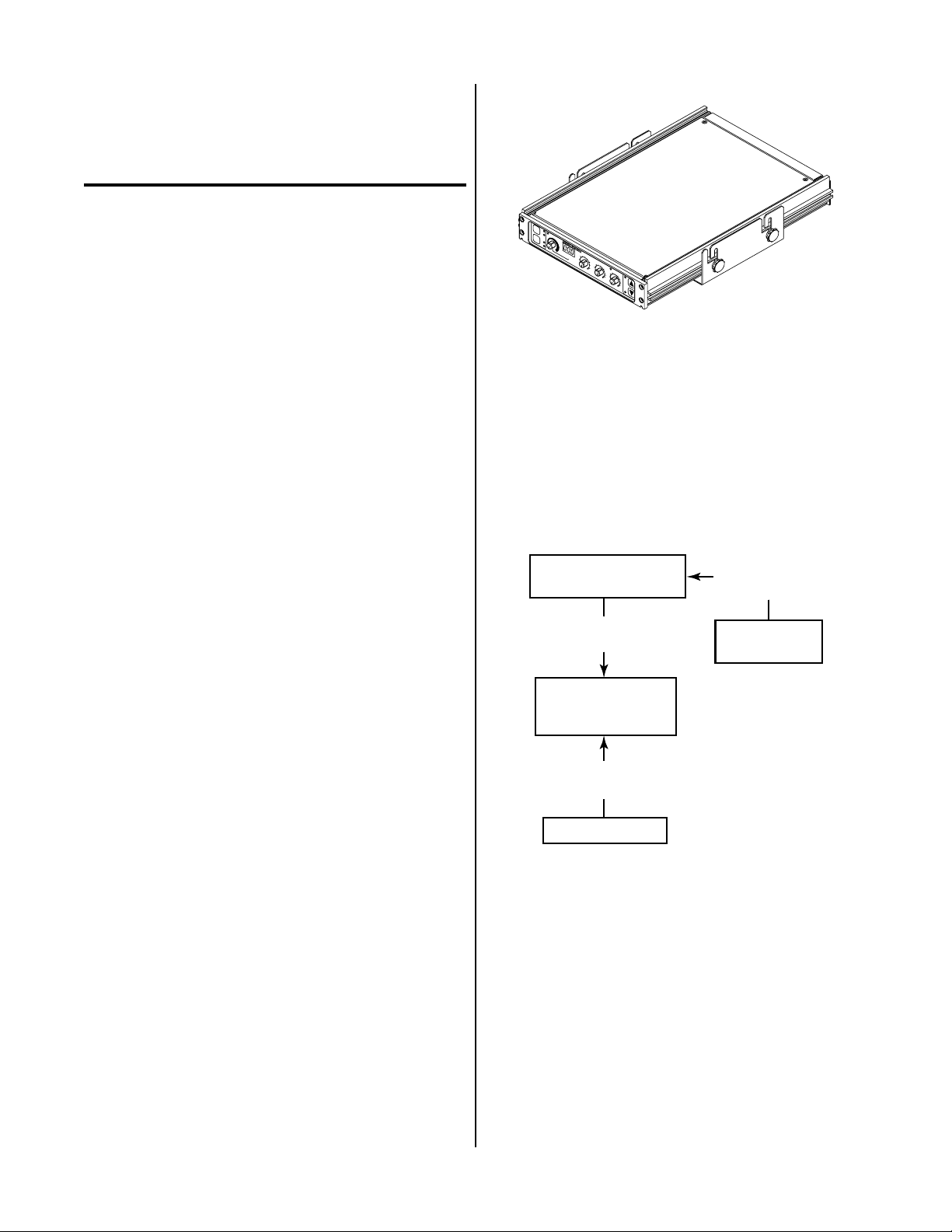
Figure 2-1 SC10 Standoff Control
The SC10 Standoff Control must be connected to the Remote Control Accessory RC6010.
There is a connection available at the rear panel for connection to the lifter motor. An internal jumper ribbon
cable also interfaces the unit to the Remote Control. The
inputs and outputs at these connections allow the various parts of the system to be operated at one station.
Remote
Control Assembly
Remote
Control Cable
The SC10 Standoff Control is designed to be used with
the RC6010 Remote Control. The Standoff Control is mechanically mated with the Remote Control, either top or
bottom, and electrically connects to the Remote Control
through a 34 circuit ribbon cable from which it receives
bias power (+48 vdc), torch voltage signal (0-12 vdc = 0200 arc volts) and sends and receives power supply and
CNC control signals such as start, arc transfer (OK-ToMove) and standoff inhibit (CSD).
The Standoff Control operates the torch lifter motor assembly to find height, regulate height and retract at end
of cut. Height is regulated by comparing the torch arc
voltage with a preset reference voltage (ARC VOLTS control) and using the resulting error voltage to raise and
lower the torch lifter motor.
Internal Jumper
Ribbon Cable
Power Supply
Assembly
Standoff
Control Accessory
Lifter Motor
Control Cable
Lifter Motor
A-00699
Figure 2-2 Modular Remote System Configuration
2.03 Specifications & Design
Features
A. Standoff Control
The following applies to the Standoff Control Assembly
only.
1. System Compatiblility
The Standoff Control Accessory was designed to be
used with various Plasma Cutting Systems
Manual 0-2479 2-1 INTRODUCTION & DESCRIPTION
Page 16

2. Input Power
48 vdc supplied from the Plasma Cutting Power Supply
3. Front Panel Controls
MODE, LIFTER SPEED, TORCH, ARC VOLTS,
PIERCE HT , PIERCE DELAY , and END OF CUT RETRACT
4. Front Panel Indicators
Arc Volts Display, PLASMA ON, AUTO HT, FIND
HT , HI, LO, T.H.C. ACTIVE, UP, and DN indicators
5. Rear Panel Connection
Lifter Motor Cable Connection
6. Dimensions (H x W x D)
2.62 x 12.12 x 10 inches (66 x 308 x 254 mm)
7. Weight
5 lbs (2.5 kg)
B. Lifter Motor
The following applies to the Lifter Motor Assembly only.
1. Dimensions (H x W x D)
29 x 10 x 8 inches (737 x 254 x 203 mm)
Refer to Appendix 5 for detailed dimensions.
2. Weight (Approximately)
20 lbs (9.07 kg)
INTRODUCTION & DESCRIPTION 2-2 Manual 0-2479
Page 17

SECTION 3:
INSTALLATION
PROCEDURES
NOTE
The V oltage Divider PC Board, Ribbon Cable and
Wire Harness Assembly will be factory installed if
ordered as part of a TD-750 Cutting System.
For Merlin 3000 Cutting Systems:
3.01 Introduction
This Section describes installation of the Standoff Control Accessory. These instructions apply to the Standoff
Control Accessory only; installation procedures for the
Plasma Power Supply and T o rches ar e given in Manuals
specifically provided for those units.
The complete installation consists of:
1. Site Selection
2. Unpacking
3. Installing Standoff Control Assembly
4. External Cable Connections
5. Lifter Motor Installation
6. Operator Training
3.02 Site Location
Select a clean, dry location with good ventilation and adequate working space around all components.
Review the safety precautions in the front of this manual
to be sure that the location meets all safety requirements.
3.03 Unpacking
• Standoff Control Assembly
• Lifter Motor Assembly
• Instruction Manual
B. Other Equipment and Accessories
Items such as Lifter Motor Control Cable, Plasma Cutting Power Supply and Torch ar e or dered and packaged
separately from the Standoff Control components.
C. Unpacking Procedure
1. Unpack each item and remove all packing material.
2. Locate the packing list(s) and use the list to identify
and account for each item.
3. Inspect each item for possible shipping damage. If
damage is evident, contact your distributor and/or
shipping company before proceeding with system
installation.
3.04 Installation - General
WARNING
Disconnect primary power to the plasma cutting
system before installating the Standoff Control.
Each component of the system is packaged separately and
protected with a carton and packing material to prevent
damage during shipping. Components are packaged as
follows:
A. Standoff Control Components
The components supplied with the Standoff Control Accessory depends on the Cutting System. The Standoff
Control Accessory components ar e packaged separately
and include:
For TD-750 Cutting Systems:
• Standoff Control Assembly
• Lifter Motor Assembly
• Voltage Divider PC Board, Ribbon Cable, and Wire
Harness Assembly
• Instruction Manual
Manual 0-2479 3-1 INST ALLATION PROCEDURES
The installation of the Standoff Control Accessory requires
mounting the Standoff Control and connecting all required cables.
The installation instructions are divided into Sub-Sections
for the component to be installed. The Sub-Sections are
as follows:
Section 3.05 Mounting Bracket Assembly Installa-
tion
Section 3.06 Standoff Control Assembly Installation
Section 3.07 Installation With TD-750 Systems
Section 3.08 Installation With Merlin 3000 Systems
Section 3.09 Internal Switch/Jumper Selections
Section 3.10 External Cable Connection
Section 3.11 Lifter Motor Installation
The Standoff Control Assembly and external cable installation is the same for all systems.
Page 18

3.05 Mounting Bracket Assembly
Installation
The Mounting Bracket Assembly is used to mount the
Standoff Control Assembly and must be installed in a suitable location where it is easily accessable to the system
operator. The unit can be mounted on top of or underneath a mounting surface.
Install the Mounting Bracket Assembly per the following
procedure:
1. Select the mounting surface for the Mounting
Bracket.
Mounting Holes
(Seven Places)
2. Mount the bracket to the surface either on top of
or underneath the surface using four 1/4" bolts
(not supplied). It is recommended to use at least
four bolts to mount the bracket but a minimum
of two are required.
NOTE
There are seven holes provided in the Mounting
Bracket. Use any four holes that are convenient
for the application.
1/4" Mounting Bolts
(Not Supplied)
A-00671
A-00672
1/4" Mounting Bolts
(Not Supplied)
Figure 3-2 Bracket Mounting Underneath Surface
3.06 Standoff Control Assembly
Installation
The Standoff Control and Remote Control must be installed together and interconnected with an internal ribbon jumper cable. The enclosures for both units are designed to be placed one on top of the other and secured
together with four #6-32x1/2 inch thread forming screws,
two in front panel and two in rear panel. It makes no
difference which unit goes on top as the installation is
the same.
Install the Remote Control and Standoff Control Assemblies per the following procedure:
1. Install the Mounting Bracket per Section 3.05.
2. Decide which unit will be the top unit, the Remote Control or the Standoff Control.
Mounting Holes
(Seven Places)
3. On the top unit remove the two cover mounting
screws on the top of the unit.
Figure 3-1 Bracket Mounting On Top Of Surface
INST ALLATION PROCEDURES 3-2 Manual 0-2479
Page 19

TORCH
MODE
LIFTER
SPEED
PLASMA
ENABLE
TRAVEL
SPEED
TORCH
MODE
LIFTER
SPEED
Screw
Cover
Screw
Standoff Control
Assembly
A
M
U
OD
T
O
H
E
T
F
IN
D
H
P
T
L
A
S
M
A
L
O
IF
N
TE
S
R
P
EE
H
D
I
L
O
R
E
ARC VOLTS
M
0
.
2
O
0
T
.
3
E
S
T
0
A
.
1
N
D
0
.
4
0
.
5
0
.
2
5
P
I
E
R
H
C
0
T
.
E
5
(
i
n
c
h
0
e
.
s
1
)
J7
O
F
F
C
O
N
0
T
.
7
R
5
O
L
1
T
.
H
.
C
.
A
C
2
T
5
I
V
E
2
P
I
E
D
R
E
C
3
L
E
A
Y
U
7
(
s
5
P
e
c
0
)
T
O
E
R
N
D
CH
R
O
E
F
1
T
C
0
R
0
U
A
T
C
T
(
%
D
)
N
A
M
U
O
T
O
D
H
E
T
F
I
N
D
H
P
T
L
A
S
M
A
L
O
I
F
N
T
E
S
R
P
E
E
H
D
I
L
O
R
E
A
M
0.2
R
O
C
0.3
T
E
V
S
O
T
L
0.1
A
T
N
S
D
O
F
F
C
0.4
O
0.5
N
0.75
T
R
O
0
.2
L
5
P
IER
1
H
C
0.
T (in
E
5
T
.
H
che
.
C
0.1
s)
.
A
C
25
T
IV
E
2
P
IER
D
ELA
C
3
E
Y
(se
U
7
5
P
c)
0
T
O
EN
R
D
C
O
R
H
ET
F
100
C
RA
U
T
C
T
(%
D
)
N
A-00689
Figure 3-3 Cover Removal
4. Remove the top enclosure cover by lifting straight
up at the rear of the cover and pulling it towards
the rear of the unit. The front edge of the cover
fits under a lip on the front panel assembly.
5. Turn the unit over.
6. Repeat Steps 3 and 4 for the bottom enclosure
cover.
7. On the bottom unit remove the two cover mounting screws on the top of the unit and remove the
top enclosure cover as in Step 4.
8. Depending on which unit is to be the bottom unit,
install the ribbon jumper cable (supplied) into one
of the following:
Remote Control
J5
A-00698
PLASMA
ENABLE
Assembly
O
N
S
T
A
R
T
R
O
E
M
U
O
T
T
P
U
T
A
M
P
S
E
P
O
W
E
R
S
U
P
P
L
Y
C
O
N
T
R
2
5
5
0
O
L
1
2
7
5
5
+
IPM
0-125
S
D
1
0
IPM
(
R
0
%
U
)
N
P
TRAVEL
U
R
G
E
SPEED
S
E
T
Figure 3-4 J7 and J5 Locations
9. Place the top unit on top of the bottom unit, feeding the ribbon cable up through the bottom of the
top unit.
10. On the top unit, connect the other end of the ribbon jumper cable into one of the following:
• Standoff Control J7 if top unit
or
• Standoff Control J7 if bottom unit
or
• Remote Control J5 if bottom unit
• Remote Control J5 if top unit
11. Secure the two units together with four #6-32x1/2
inch thread forming screws (supplied) inserted at
the front and rear panels (two screws each) in the
holes provided.
Manual 0-2479 3-3 INST ALLATION PROCEDURES
Page 20

RUN
TORCH
PURGE
SET
14. Set the assemblied units into the Mounting
Bracket being sure the four bolts are in the mounting slots.
Mounting Bracket
#6-32 x 1/2"
Thread Forming
Screw
UP
TORCH
DN
A-00696
Figure 3-5 Screw Installation
12. Reinstall the top enclosure cover on the top unit
securing it with the two screws removed earlier.
13. Insert two of the #10-32 x 3/8" hex head bolts into
the slots on each side of the bottom or top unit
per one of the following:
• Bracket Mounted On Top Of Surface
Insert bolts in the bottom unit if the Mounting
Bracket was installed for top surface mounting.
• Bracket Mounted Underneath Surface
Insert bolts in the top unit if the Mounting
Bracket was installed for underneath surface
mounting.
Knob
Hex Head
Bolts
A-00674
Knob
Figure 3-7 Knob Installation
15. Place one knob on each of the bolts protruding
from the bracket slots.
16. The assemblied units can be adjusted for the best
viewing angle. The units can be tilted up to 10°.
Adjust the viewing angle per the following:
a. Loosen the four knobs sercuring the
assemblied units to the Mounting Bracket.
b. Adjust the assembled units for the desired
angle.
c. Tighten all four knobs.
d. If the angle is not correct, loosen knobs, read-
just until proper viewing angle is found, and
retighten all knobs.
The slot prevents the bolts from turning when the
knobs are installed.
A-00688
U
P
TORCH
D
N
Hex Head Bolt
#10-32 x 3/8"
Knob
Figure 3-6 Bolt Installation
Slot
3.07 Installation With TD-750
Systems
This Section describes the installation of components to
allow use of the Standoff Control with a TD-750 Cutting
System.
NOTE
For orders that included the Standoff Control as
part of the complete system these components are
factory installed. Proceed to Section 3.09 Internal
Selections.
For orders where the Standoff Control is to be added to
the TD-750 Cutting System the procedures in this subsection must be completed.
The TD-750 must have the proper remote output connection at the rear of the TD-750 Power Base Unit. For TD750 Systems that do not have the proper remote output
installed in the TD-750 Power Base Unit proceed with
INST ALLATION PROCEDURES 3-4 Manual 0-2479
Page 21

the following. With systems that already have the remote output accessory installed at the rear panel proceed
to paragraph 'C. Voltage Divider PC Board Installation'.
C. Voltage Divider PC Board Installation
WARNING
WARNING
Disconnect primary power at the source before assembling or disassembling stacked modules, individual modules, torch parts, or torch and leads assemblies.
The right side of the Power Base Unit must be removed
to install the remote output assembly.
A. Removing Side Panel
1. Using a phillips head screwdriver remove the
eight screws securing the right side panel to the
Power Base Unit. The two screws in the slotted
holes need only be loosened for the panel to be
removed.
Disconnect primary power at the source before assembling or disassembling power supply, torch
parts, or torch and leads assemblies.
Introduction
Parts of the Standoff Control must be installed inside the
TD-750 Control Module Assembly (CM6033). The instructions in this section covers only the installation of
those parts.
NOTE
These instructions are for TD-750 Control Modules (CM6033) Only.
Standoff Control components to be installed inside the
Control Module include:
• Voltage Divider Wire Harness - 1 each
• #6-20 x 3/8 Phillips Head Thread Cutting Screws
- 4 each
• PC Board supports - 4 each
• Voltage Divider Ribbon Cable - 1 each
Right Side Panel
Screws, External Star Washers
A-00675
and Flat Washers (8-Places)
Figure 3-8 Screw Removal Details
2. Slide the right side panel to the right to disengage
the two screws in the slotted holes.
3. Pull the right side panel from the Power Base Unit.
B. Installation Of Remote Output
Install the remote output assembly per the instructions
supplied with the assembly.
• Voltage Divider PC Board - 1 each
Opening the Enclosure
The upper half of the control module enclosure must be
removed to install the wire harness and Voltage Divider
PC Board.
1. Unscrew and remove the two module assembly
pins which secure the upper control module enclosure to the lower.
Module Assembly Pins
A-00049
Upper Enclosure
II
K
A
T
S
E
S
S
A
T
/
Y
R
A
S
D
A
N
G
O
E
C
L
G
N
I
N
O
D
R
A
D
P
N
M
A
E
T
S
S
K
P
R
M
H
O
A
C
W
T
S
A
A
L
G
C
D
R
E
H
F
C
S
R
N
O
A
T
R
T
-
T
I
O
H
L
I
P
N
U
R
E
G
R
U
P
T
E
S
A
M
S
CURRENT
A
L
S
P
A
G
K
A
P
K
A
T
A
S
D
S
C
C
Figure 3-9 Module Pin Removal
Manual 0-2479 3-5 INST ALLATION PROCEDURES
Page 22

It may be necessary to use a flat blade screwdriver
to pry the pin outward from the top until the
threads engage. Use a 5/16 nut driver to fully
remove the Module Assembly Pins .
Logic PCB
Assembly
Flat Blade
Screwdriver
5/16 Inch
Nut Driver or
Socket
A-00532
Figure 3-10 Pin Removal Detail
2. Lift the upper enclosure from the control module.
Installing Voltage Divider PCB Assembly
Install the Voltage Divider PCB Assembly as follows:
1. Locate the divider panel inside the control module.
Analog PCB
Assembly
Divider Panel
Voltage Divider
PCB Assembly
A-01019
Figure 3-11 Voltage Divider PCB Installation
Ribbon Cable Installation
2. Locate the Voltage Divider PCB Assembly included with the Standoff Control components.
The standoffs are factory mounted to the PC
Board.
3. Install the V oltage Divider PCB assembly onto the
divider panel placing the standoffs into the lower
four holes in the divider panel.
NOTE
The Ribbon Cable (10 pin) is connected to the V oltage Divider PCB at the factory. The information
is supplied to insure proper installation.
Install the Ribbon Cable Assembly as follows:
1. Connect the ribbon cable to the Voltage Divider
PCB per the following figure:
INST ALLATION PROCEDURES 3-6 Manual 0-2479
Page 23

Voltage Divider
PC Board
Ribbon Cable
(10-Pin)
Voltage Divider
PC Board
A-01020
Figure 3-12 Ribbon Cable Assembly
2. Route the ribbon cable to the rear of the voltage
selection plugs and through the notch in the divider panel.
3. Continue routing the ribbon cable around the end
of the Analog PCB Assembly to the J1 1 receptacle
located at the rear panel.
4. Connect the ribbon cable to the 10-pin connector,
J32, on the side of the J11 r eceptacle located at the
rear panel.
Pilot Wire Harness Installation
NOTE
The wire harness is connected to the Voltage Divider PCB at the factory. The information is supplied to insure proper installation.
P.S. +
(56)
to Pilot PCB
(J8)
P.S. -
Connector
A-01021
(54)
Figure 3-13 Pilot Wire Harness Assembly
2. Connect the plug on the Wire Harness Assembly
to J8 on the Pilot PCB Assembly.
J8
Wire Harness
Connector To
Pilot PC Board
Pilot PCB
A-00527
Figure 3-14 Connection to Pilot PCB
Install the Pilot Wir e Harness Assembly as follows:
1. Connect the two wires from the wire harness cable
to the Voltage Divider PCB Assembly per the following:
W ire Voltage
Pin N umber Divider Connection
356 P.S. +
754 P.S. -
Reinstall the enclosure cover by reversing the steps in
“Opening The Enclosure” above.
This completes the installation of the components inside
the TD-750 Control Module (CM6033).
3.08 Installation With Merlin 3000
Systems
There are no additional components that must be installed
inside the Merlin 3000 Power Supply. Proceed to SubSection 3.09.
Manual 0-2479 3-7 INST ALLATION PROCEDURES
Page 24

3.09 Internal Selections
TORCH
MODE
LIFTER
SPEED
A. Switch (SW1) Selection
The Standoff Control Assembly has one internal switch
(SW1) that is used for some plasma cutting systems without an arc transfer or motion signal. Turning ON SW1-1
and SW1-2 will generate the signal as soon as the pilot
arc voltage drops from open circuit to under 195v. This
occurs as soon as pilot is initiated so the PIERCE DELAY
should be used to delay the motion signal. This will allow time for arc transfer and piercing. Switch SW1 is not
needed for the TD-750 System and both positions should
be in the OFF position.
T o check or change the switch selection use the following
procedure:
1. Remove the two cover mounting screws on the top of
the Standoff Accessory.
System SW 1-1 SW1-2
Other Systems ON ON
TD-750 Systems OFF * OF F*
* = F act ory Set tin g
NOTE
Refer to Section 4.04-E for operation when starting the the cutting operation off the plate (workpiece).
Standoff Control
PC Board Assembly
Screw
Screw
Cover
A
M
U
O
T
O
D
H
E
T
F
I
N
D
H
PLASM
T
A O
L
I
F
N
T
E
S
R
P
E
E
H
D
I
L
O
R
E
ARC VOLTS
M
0
.2
O
0
T
.3
E
S
T
0
A
.1
N
D
O
F
F
C
0
.4
O
0
.5
N
0
T
.7
R
5
O
0
.2
L
5
P
I
E
R
1
H
C
0
T
.5
E
(i
T.H.C. A
n
c
h
0
e
.1
s
)
CTIVE
2
57
2
P
IE
D
R
E
C
3
L
E
A
Y
(s
UP
5
e
c
0
)
T
O
E
R
N
D
C
O
R
H
E
F
1
T
C
0
R
0
U
A
T
C
T
(
%
DN
)
A-00689
Figure 3-15 Cover Removal
2. Remove the enclosure cover by lifting straight up at
the rear of the cover and pulling it towards the r ear of
the unit. The front edge of the cover fits under a lip
on the front panel assembly.
ON
A-00861
1
2
SW1
Type System
Selection
Figure 3-16 Switch SW1 Location
B. J11 Isolated CNC Interface
For the TD-750 System the CNC interface is through the
Remote Control. Do not use J1 1 on the Standoff Contr ol.
For other systems an isolated START, standoff inhibit
(CSD) and motion (OK-To-Move) selectable for contact
closure or 24 VAC is available at J11.
3.10 External Cable Connections
3. Identify internal switch SW1 and confirm that the
switch is set for the desired system as follows:
The Standoff Control has only one output connector on
the rear panel. The Lifter Motor Control Cable is connected to this output. The other end of the cable is connected to the lifter motor equipment.
Signals include drive (up to +/-20 vdc), tach (0 to +/- 15
vdc) and normally closed (NC) TORCH ON WORK
switch.
INST ALLATION PROCEDURES 3-8 Manual 0-2479
Page 25

3. Route the Torch Leads up and over the Hose
MOTOR
J43
Holder.
4. Connect the end of the Torch Leads per the appropriate Torch Manual.
A-00690
Lifter Motor
Control Cable
Figure 3-17 Cable Connections
3.11 Lifter Motor Installation
A. Mounting Holes
NOTE
Refer to the exploded view of the Lifter Motor Assembly for parts location and assembly.
The Lifter Motor Assembly must be mounted to the Cutting T able. Mount the assembly per the following procedure:
1. Lossen the four screws securing the Front Cover
to the assembly.
2. Remove the Front Cover from the assembly.
3. Use the template at the end of this Manual to locate the four mounting holes noting the following:
• The bottom edge of the Lifter Motor Assem-
bly must be able to clear and obstructions in
the cutting path.
• The assembly must be mounted low enough
to allow proper operation of the T orch Assembly.
4. Drill and tap four holes for 1/4-20 bolts.
5. Mount the Lifter Motor Assembly to the four
tapped holes using the four bolts and washers
supplied.
6. Reinstall the Front Cover and tighten the four
cover screws.
B. Torch Assembly Installation
1. Place the end of the Rack and Pinion Assembly
into the Torch Holder Pivot.
2. Tighten the wing nut and washer to secure the
Rack and Pinion Assembly to the Lifter Motor Assembly.
Manual 0-2479 3-9 INST ALLATION PROCEDURES
Page 26

INST ALLATION PROCEDURES 3-10 Manual 0-2479
Page 27

SECTION 4:
TORCH
MODE
LIFTER
SPEED
OPERATION
Pressing MODE a third time turns both indicators
OFF for fully manual mode. Pressing MODE the
forth time returns to fully automatic operation.
2. LIFTER SPEED Pushbutton and Indicators
4.01 Introduction
The momentary LIFTER SPEED pushbutton switch
selects one of two torch lifter speeds.
This Section provides a description of the Standoff Control Accessory followed by operating pr ocedur es.
• High speed - HI indicator ON and LO indicator OFF
• Low speed - LO indicator ON and HI indicator OFF
4.02 Functional Overview
The Standoff Control Accessory extends the necessary system controls away from the power supply and is an accessory with standard machine torch systems.
There is a connection available at the Standoff Control
Accessory for the lifter motor control cable. There is an
internal ribbon cable connection between the Standoff
Control and the Remote Control Accessories that provides
inputs and outputs to allow various parts of the system
to be operated from one station.
Pressing the LIFTER SPEED switch toggles between
HI and LO.
When power is supplied the Standoff Control automatically selects the HI Lifter Speed mode. The HI
indicator will be ON. Pressing LIFTER SPEED once
turns HI indicator OFF and LO indicator ON. Pressing LIFTER SPEED the thrid time returns to the HI
Lifter Speed mode.
At lower cutting speeds the HI mode may cause oscillation or diving toward the work during the cut. If
this happens it is recommended that the operator se-
4.03 Operating Controls
A. Front Panel
lect the LO lifter speed.
3. PLASMA ON Indicator
When the Standoff Control sends a start signal to the
MODE
LIFTER
SPEED
3
PLASMA ON
4
ARC VOLTS
5
REMOTE STANDOFF CONTROL
0.3
0.2
0.4
0.1
0.5
PIERCE
HT (inches)
8
6
0.75
0.5
1
PIERCE
DELAY (sec)
25 75
2
0
3
0.25
0.1
T.H.C. ACTIVE
END OF CUT
RETRACT (%)
100
A-00691
UP
TORCH
DN
1
AUTO
HT
FIND
HT
HI
LO
Plasma Power Supply the PLASMA ON indicator
turns ON. The start signal is sent automatically after
finding height.
4. ARC VOLTS Control and Display
The ARC VOLTS control allows the operator to se-
2
7
9
lect the desired arc voltage from 65 to 195, as indicated at the ARC VOLTS Display. Volts above 199
Figure 4-1 Front Panel Operating Controls
will cause the display to indicate over range (left display digit is "1"). The standoff, distance from torch
1. MODE Pushbutton and Indicators
to work, may be changed during cutting by changing the ARC VOLTS setting.
The momentary MODE pushbutton switch selects
one of four modes of operation.
Prior to enabling the PLASMA ON indicator a decimal point will be displayed on the right hand side of
• Fully automatic - AUTO HT and FIND HT in-
dicators ON
• Automatic height - AUTO HT indicator ON
and FIND HT indicator OFF
• Find height - AUTO HT indicator OFF and
FIND HT indicators ON
the ARC VOLTS Display indicating preview mode.
After the PLASMA ON indicator is turned ON the
ARC VOLTS Display indicates the actual arc volts
from 0 to 199.
Three decimal points displayed in the ARC VOLTS
Display indicate the Standoff Control is receiving a
corner slowdown (CSD) inhibit signal.
• Fully Manual - AUTO HT and FIND HT indi-
cators OFF
If the Station Select (CNC) or Enable are OFF in the
Remote Control, then the Standoff Control ARC
When power is supplied the Standoff Control enters
VOL TS Display will blank.
the fully automatic mode. The AUTO HT and FIND
HT indicators will be ON. Pressing MODE once turns
FIND HT indicator OFF . Pressing MODE again turns
AUTO HT indicator OFF and FIND HT indicator ON.
Manual 0-2479 4-1 OPERA TION
Page 28

5. PIERCE HT (inches) Control
9. TORCH UP/DN Pushbuttons and Indicators
The PIERCE HT (height) controls the starting distance
from torch to workpiece from nearly zero to 1/2
inches.
After receiving a start signal with one of the FIND
HT modes selected, FIND HT indicator ON, the
standoff control equipment lowers the torch fr om the
retracted position until it contacts the metal to be cut.
The standoff equipment then lifts the torch back up
the distance above the plate set by the adjustable
PIERCE HT control from nearly zero to over 1/2".
When doing a piercing operation it is best to start
from the highest possible position to minimize splatter onto the end of the torch. Splatter onto the torch
shield and tip can block the cutting tip orifice.
6. PIERCE DELAY (sec) Control
The PIERCE DELAY controls the arc transfer (OKTo-Move) or motion start signals to the cutting machine. This delay allows time for the arc to pierce
through the material. The delay time is adjustable
from zero to over thr ee seconds.
NOTE
The cutting machine controller may also have a
motion delay which will add to the total delay, if so
it should be set to zero.
The momentary TORCH UP/DN pushbutton
switches allow setting the torch position manually.
Pressing the TORCH UP switch will cause the UP indicator to turn ON. The DN (Down) indicator turns
ON if the TORCH DN pushbutton is pressed.
The manual control may be used to set initial height
when the FIND HT indicator is OFF. The controls
can also be used to adjust the standoff when the
AUTO HT indicator is OFF.
The manual controls should not be used while cutting if the AUTO HT indicator is ON (see ARC VOL TS
Control).
B. Rear Panel
The Standoff Control rear panel has only one output connector for the lifter motor assembly cable. Signals include
drive (up to +/-20 vdc), tachometer (0 to +/- 15 vdc) and
TORCH ON WORK switch (NC).
4.04 Sequence Of Operations
This Section describes the typical sequences for various
operations. The information is suppied to give the operator an understanding of what is occuring during the
cutting cycle. Each of the following paragraphs describe
a different operation as follows:
Height regulation will be inhibited during the delay
time selected.
7. END OF CUT RETRACT (%) Control
The END OF CUT RETRACT contols the raising (retracting) of the torch from zero to 100% of the selected
setting of the END OF CUT RETRACT (%) Control.
With one of the FIND HT modes selected, FIND HT
indicator ON, the torch is raised at the end of a cut
operation when the start signal is removed. The
amount of time that it takes to raise the torch can be
reduced by not retracting the torch fully, if not required.
8. T.H.C. ACTIVE Indicator
The T.H.C. (Torch Height Control) ACTIVE indicator turns ON when the height is under active control. The T.H.C. ACTIVE indicator turns OFF when
no initial arc transfer signal is received, corner slowdown (CSD) inhibit signal is on, or the voltage is rising rapidly. When the T.H.C. ACTIVE indicator is
OFF the standoff is not being regulated during that
time.
• Paragraph ‘A ’ - Fully Automatic Mode With Pierce
Start
• Paragraph ‘B’ - AUTO HT ON and FIND HT indi-
cators OFF
• Paragraph ‘C’ - AUTO HT Indicator OFF and FIND
HT Indicator ON
• Paragraph ‘D’ - Fully Manual Mode
• Paragraph ‘E’ - Starting Off The Plate
A. Fully Automatic Mode (AUTO HT and FIND
HT Indicators ON) With Pierce Start
1. The cutting machine controller sends a start signal to the Standoff Control through the Remote
Control (RC6010).
2. The Standoff Control starts to find height by rapidly lowering the torch from the retracted position towards the work. When the torch contacts
the work or the bottom of torch travel if not over
the work, it opens the normally closed (NC) torch
on work (T.O.W.) switch in the Lifter Motor Assembly.
The voltage rising rapidly can be caused by cutting
over a kerf, other hole, or an arc voltage outside the
regulation limits of 65 to 195 volts
OPERA TION 4-2 Manual 0-2479
Page 29

3. When the T.O.W. switch opens, the torch downward motion is reversed and it slowly rises until
the T .O.W . switch closes which starts the PIERCE
HT timer. The torch continues upward for the
time required to reach the selected pierce height
setting.
4. A start signal is sent to the Plasma Power Supply
and the Standoff Control PLASMA ON indicator
turns ON. The pilot starts after pre-flow and immediately, if the initial height is correct, the cutting arc is established at which time the Plasma
Power Supply sends an OK-T o-Move signal to the
Standoff Control through the Remote Contr ol.
2. A start signal is sent to the Plasma Power Supply
and the Standoff Control PLASMA ON indicator
turns ON. The pilot starts after pre-flow and immediately, if the initial height is correct, the cutting arc is established at which time the Plasma
Power Supply sends an OK-T o-Move signal to the
Standoff Control through the Remote Contr ol.
3. Receiving the OK-To-Move signal from the
Plasma Power Supply starts the PIERCE DELAY.
As the PIERCE DELA Y ends the OK-To-Move signal is sent to the cutting machine controller
through the Remote Control starting the horizontal travel.
5. Receiving the OK-To-Move signal from the
Plasma Power Supply starts the PIERCE DELAY.
As the PIERCE DELA Y ends the OK-To-Move signal is sent to the cutting machine controller
through the Remote Control starting the horizontal travel.
6. At the same time, the T.H.C. ACTIVE indicator
turns ON and the torch moves to the desired cutting standoff as determined by the pre-selected
ARC VOL TS Control, unless the cutting machine
corner slowdown (CSD) is ON, or the arc voltage
is outside the range of 65 to 195V inhibiting it.
Even if the standoff is inhibited, because the cut
is starting in a corner , the controller is enabled for
1/2 second to position the torch down to the
proper cutting height. Without this feature the
first few inches could be cut at excessive standoff
adversely affecting the quality.
7. The piece is cut then the cutting machine removes
the start signal. The arc goes out removing the
OK-To-Move from the Plasma Power Supply.
8. When both the start and OK-To-Move signals are
removed (allows for current ramp down for systems that have that feature) the retract timer is
activated to rapidly raise the torch up to clear obstructions, such as cut out pieces that tilt up, while
traversing to the next piece to be cut. The amount
of retract is set from zer o to 100% by the END OF
CUT RETRACT Control. The torch remains retracted until the sequence repeats with the next
start signal.
B. AUTO HT ON and FIND HT indicators OFF
The operator sets the torch height manually. Refer to
paragraph 'D' for "Starting Off The Plate (W orkpiece)".
1. The cutting machine controller sends a start signal to the Standoff Control through the Remote
Control (RC6010).
4. At the same time, the T.H.C. ACTIVE indicator
turns ON and the torch moves to the desired cutting standoff as determined by the pre-selected
ARC VOL TS Control, unless the cutting machine
corner slowdown (CSD) or the arc voltage is outside the range of 65 to 195v inhibiting it , . Even
if the standoff is inhibited, because the cut is starting in a corner, the controller is enabled for 1/2
second to position the torch down to the proper
cutting height. Without this feature the first few
inches could be cut at excessive standoff adversely
affecting the quality.
5. The piece is cut then the cutting machine removes
the start signal. The arc goes out removing the
OK-To-Move from the Plasma Power Supply.
6. The torch does not retract.
C. AUTO HT Indicator OFF and FIND HT
Indicator ON
NOTE
The standoff height is not controlled during the
cut except manually by the operator using the
TORCH UP/DN switches.
1. The cutting machine controller sends a start signal to the Standoff Control through the Remote
Control (RC6010).
2. The Standoff Control starts to find height by rapidly lowering the torch from the retracted position towards the work. When the torch contacts
the work or the bottom of torch travel if not over
the work, it opens the normally closed (NC) torch
on work (T.O.W.) switch in the Lifter Motor Assembly.
3. When the T.O.W. switch opens the torch downward motion is reversed and it slowly rises until
the T .O.W . switch closes which starts the PIERCE
HT timer. The torch continues upward for the
time required to reach the selected pierce height
setting.
Manual 0-2479 4-3 OPERA TION
Page 30

4. A start signal is sent to the Plasma Power Supply
and the Standoff Control PLASMA ON indicator
turns ON. The pilot starts after pre-flow and immediately, if the initial height is correct, the cutting arc is established at which time the Plasma
Power Supply sends an OK-T o-Move signal to the
Standoff Control through the Remote Contr ol.
5. Receiving the OK-To-Move signal from the
Plasma Power Supply starts the PIERCE DELAY.
As the PIERCE DELA Y ends the OK-To-Move signal is sent to the cutting machine controller
through the Remote Control starting the horizontal travel.
NOTE
Torch height is not controlled automatically.
6. The piece is cut then the cutting machine removes
the start signal. The arc goes out removing the
OK-To-Move from the Plasma Power Supply.
7. When both the start and OK-To-Move signals are
removed (allows for current ramp down for systems that have that feature) the retract timer is
activated to rapidly raise the torch up to clear obstructions, such as cut out pieces that tilt up, while
traversing to the next piece to be cut. The amount
of retract is set from zer o to 100% by the END OF
CUT RETRACT Control. The torch remains retracted until the sequence repeats with the next
start signal.
D. Fully Manual Mode (AUTO HT and FIND HT
Indcators OFF)
3. Receiving the OK-To-Move signal from the
Plasma Power Supply starts the PIERCE DELAY.
As the PIERCE DELA Y ends the OK-To-Move signal is sent to the cutting machine controller
through the Remote Control starting the horizontal travel.
4. The piece is cut then the cutting machine removes
the start signal. The arc goes out removing the
OK-To-Move from the Plasma Power Supply.
E. Starting Off The Plate (Workpiece)
When starting off the plate (running edge start) FIND
HT indicator should be OFF and height set manually. AUTO HT indicator is normally ON to control
height after the cut starts.
When starting off the plate no motion signal (OK-T oMove) will be generated to move the torch over the
metal. The Remote Control (RC6010) has an internal
dip-switch SW2-1 and SW2-2 which when turned on
generates OK-To-Move when the pilot starts (actually when the power supply is enabled. We are assuming pilot starts with no delay). The standoff control won’t try to regulate height until the real
OK-To-Move occurs (and the PIERCE DELAY ends)
after the torch reaches the metal and the cutting arc
is established. Some PIERCE DELA Y may be r equired
to allow time for the arc voltage to stabilize before
trying to regulate. SW1 (refer to Section 3.08, Internal Selections) on the Standoff PC Board could be
used but isn’t as good as it will try to regulate height
after the PIERCE DELAY even if the arc is not transferred.
NOTE
Initial height is set manually and controlled manually during cutting. PIERCE DELAY is still active and the arc volts display indicates actual arc
volts but the ARC VOL TS control will not change
the standoff.
1. The cutting machine controller sends a start signal to the Standoff Control through the Remote
Control (RC6010).
2. A start signal is sent to the Plasma Power Supply
and the Standoff Control PLASMA ON indicator
turns ON. The pilot starts after pre-flow and immediately, if the initial height is correct, the cutting arc is established at which time the Plasma
Power Supply sends an OK-T o-Move signal to the
Standoff Control through the Remote Contr ol.
If FIND HT indicator is ON the OK-To-Move signal
from the pilot start is disabled so it is possible to do
both pierce and off the plate starts by leaving the Remote Control internal switch SW2 set to ON and selecting FIND HT for piercing. In this case do not use
FIND HT for off the plate starts.
NOTE
Refer to the Remote Control (RC6010) Instruction
Manual 0-2478 for more information on setting
the internal switches in the Remote Control Assembly.
OPERA TION 4-4 Manual 0-2479
Page 31

SECTION 5:
5.03 Troubleshooting Guide
CUSTOMER/OPERATOR
SERVICE
5.01 Introduction
This Section describes basic maintenance procedures performable by operating personnel. No other adjustments
or repairs are to be attempted by other than Thermal
Dynamics T rained personnel.
WARNINGS
Disconnect primary power at the source before disassembling any part of the cutting system.
Frequently review the Important Safety Precautions in Section 1. Be sure the operator is equipped
with proper gloves, clothing, eye and ear protection. Make sure no part of the operator’s body comes
into contact with the workpiece while the cutting
system is activated.
Sparks from the cutting process can cause damage
to coated, painted, and other surfaces such as glass,
plastic and metal.
A. Troubleshooting
This Sub-Section covers troubleshooting that requires
dissasembly and electronic measurements. It is helpful
for solving many of the common problems that can arise
with the Standoff Control Assembly.
WARNING
There are extremely dangerous voltage and power
levels present inside this unit. Do not attempt to
diagnose or repair unless you have had training in
power electronics measurement and troubleshooting techniques.
Specific test procedures are referenced by the troubleshooting guide.
The guide has two sections as follows:
Section 5.04 - Troubleshooting Specific Problems
Section 5.05 - Test Procedures
B. How to use this Guide
The following information is a guide to help the Customer/Operator determine the most likely causes for
various symptoms.
5.02 Routine Maintenance
The only routine maintenance required for the Standoff
Control components is a thorough cleaning and inspection, with the frequency depending on the usage and the
operating environment.
To clean the Standoff Control, first make sure that the
power is disconnected. Open the Standoff Control enclosure and blow out any accumulated dirt and dust with
compressed air. The unit should also be wiped clean. If
necessary, solvents that are recommended for cleaning
electrical apparatus may be used.
While the enclosures are open, inspect the wiring in the
unit. Look for any frayed wires or loose connections that
should be corrected.
This guide is set up in the following manner:
X. Symptom (Bold Type)
Any Special Instructions (Text Type)
1. Cause (Italic Type)
a. Check/Remedy (Text Type)
Locate your symptom, check the causes (easiest listed first)
then remedies. Repair as needed being sure to verify that
unit is fully operational after any repairs.
NOTE
Many signals are transfered between various assemblies on interconnecting cables. If these cables
become faulty they can then cause various problems. Do not forget about these cables when
troubleshooting.
Manual 0-2479 5-1 CUSTOMER/OPERATOR SER VICE
Page 32

5.04 Troubleshooting Specific
Problems
A. Front panel switch for MODE, LIFTER SPEED,
TORCH UP or TORCH DOWN will not function
1. Connector J3 on the Standoff Control PC Board is connected one pin off
a. Make sure connector is plugged in correctly.
2. Faulty front panel switch or Standoff Contr ol PC Board
NOTE
The mounting bolts attaching the torch lead support bracket to the Torch Lifter Assembly can bind
if the mounting bolts are too long.
2. Faulty torch lifter motor or cable
a. Check the motor and cable per Section 5.05-D,
repair as necessary
E. Torch moves down to work but does not retract to
PIERCE HT setting
a. Test per Section 5.05-B and replace faulty as-
sembly as required
B. One or more, not all, front panel indicators will
not turn ON when expected
1. Faulty indicator or Standoff Control PC Board
a. Test per Section 5.05-C and replace fr ont panel
assembly if necessary
C. Torch will not move up or down manually using
TORCH UP and TORCH DOWN switches;
TORCH UP and TORCH DOWN indicators come
ON
1. Torch Lifter Assembly rack and pinion gear misaligned
or not meshing
a. Lift up on the torch while pressing the T ORCH
UP arrow to remesh the gears. May need to do
this several times to get the motor moving.
2. Dirty Lifter Slide or Rollers
a. Remove cover and clean Slide and Rollers
3. Mounting screw of T or ch Lead Support Bracket too long
a. Replace with shorter screw
NOTE
The mounting bolts attaching the torch lead support bracket to the Torch Lifter Assembly can bind
if the mounting bolts are too long.
D. Torch will not move or no pilot arc when START is
pressed
Push front panel TORCH UP or TORCH DOWN
switch to see if torch will move manually. If torch
will move in either direction, then torch lifter motor
and cable are okay.
1. PIERCE HT control is set fully counterclockwise
(CCW), minimum standoff
a. Adjust for higher standoff
2. Tip-On-Work micro-switch faulty, out of adjustment
or slide frozen so switch cannot be activated
a. Check the Tip-On-W ork micro-switch per Sec-
tion 5.05-E, repair as necessary
F. Torch moves down to the work and retracts, but
stops at a point higher than the PIERCE HT
setting or continues to a point at the top of travel;
Pilot may activate when the travel stops
1. Tip-On-Work micro-switch circuit is faulty or have
dirty contacts
a. Check the Tip-On-W ork micro-switch per Sec-
tion 5.05-E, repair as necessary
G. Torch moves up instead of down when it should
be finding height
1. Tip-On-Work micro-switch cir cuit is open
a. Check the Tip-On-W ork micro-switch per Sec-
tion 5.05-E, repair as necessary
H. Torch finds height and starts cutting but cutting
machine doesn’t move
1. OK-To-Move signal not compatible with cutting machine controller . Signal set for contacts, but contr oller
needs AC volts or vice versa.
a. Change setting. Refer to Remote Control
(RC6010) Instruction Manual.
2. Faulty OK-To-Move signal
a. Check for proper OK-To-Move signal per Sec-
tion 5.05-F, repair as necessary
1. Check for binding of the torch lifter assembly slide.
a. Repair as required
CUSTOMER/OPERATOR SER VICE 5-2 Manual 0-2479
Page 33

I. After cutting starts torch remains at initial height;
THC ACTIVE indicator is OFF
1. Automatic find height not activated, AUTO HT indicator OFF
a. Press MODE control switch until AUTO HT in-
dicator comes ON
2. Faulty Arc voltage input to Standoff Control
a. Check for proper arc voltage input per Section
5.05-G, repair as necessary
J. Torch dives or oscillates while cutting instead of
maintaining constant height
1. Lifter speed set too high
a. For travel speeds under150 inches per minute
select low speed
2. Faulty motor tachometer
a. Check the motor/tachometer per Section 5.05-
H, repair as necessary
8. The THC ACTIVE indicator turns ON and the
Standoff Control regulates height to maintain the
selected standoff.
9. At times during the cutting operation the
controllor program may disable the Standoff Control by applying the CSD signal. When this occurs all three decimals in the ARC VOL TS display
turn ON and the THC ACTIVE indicator will turn
OFF.
10. At the end of the cut program the ST AR T signal is
removed.
11. The torch retracts at high speed to the setting of
the END OF CUT RETRACT (%) control . This
setting is a percentage (%) of the full lifter travel.
If the FIND HT indicator is OFF, the system will
skip the find height sequence and the retract at
the end of the cut. The desired pierce height is set
manually.
If the AUTO HT indicator is OFF, height is not
controlled during the cut.
5.05 Test Procedures
This section describes the tests required to isolate problems or faulty assemblies in the Standoff Control Assembly. The section contains a functional description of the
Standoff Control followed by individual test pr ocedures.
Each procedure is referenced in Section 5.04, Troubleshooting Specific Problems.
A. Functional description
The Standoff Control controls the operation of the torch
lifter motor assembly to find height, regulate height and
retract at the end of cut per the following sequence:
1. Standoff Control receives a START signal.
2. Torch moves down at high speed until the torch
tip contacts the workpiece.
3. T or ch retracts at slow speed to the setting selected
by the PIERCE HT control.
4. Upon finding height as set by the PIERCE HT control a START signal is sent to the plasma power
supply and the PLASMA ON indicator turns ON.
5. The power supply starts the arc which pierces the
metal.
6. After the time delay as set at the PIERCE DELAY
ends, an OK-T o-Move signal is sent to the cutting
machine to start the cutting motion.
The T orch Lifter Assembly uses a dc motor with a tachometer for speed and direction feedback. The motor pinion
gear mates with a rack on the up/down slide to move
the torch. A second small vertical slide allows about 1/2
inch of free movement. Held down by the weight of the
torch it keeps the Tip-On-Work micro-switch (mounted
above the small slide) closed. When finding height, as
the torch moves downward and makes contact with the
the work, the small slide moves up, opening the microswitch to signal that the torch has made contact with the
work.
B. Front Panel Switch Tests
The four switches have a common connection to J3-
13. T o check the operation of the switch measur e for
continuity from the PC Board common (TP1) to the
other side of the switch at J3 per the following:
Sw itch J3 Pin #
MODE 8
LIFT ER SP EED 12
TORCH UP 17
TORCH DO WN 14
7. As the cutting machine accelerates the standoff
inhibit or corner slowdown (CSD) signal is removed.
Manual 0-2479 5-3 CUSTOMER/OPERATOR SER VICE
Page 34

MODE
LIFTER SPEED
UP
J3-8
J3-12
AUTO HT
FIND HT
+V1
J3-4
J3-7
J3-5
J3-17
DOWN
J3-14
J3-13
A-01076
The measurement should be less than 200 to 300 ohms
when the switch is pushed.
If the measurement is not correct the switch is faulty;
replace front panel assembly.
If the measurement is correct then the Standoff Control PC Board is faulty; replace the complete Standoff Control Assembly.
C. Front Panel Indicator Tests
For all indicators, except TORCH UP and TORCH
DOWN, measure the dc voltage from PC Board common (TP1) to the J3 pin for the indicator cathode per
the following:
J3-6
HI
LOW
PLASMA ON
THC ACTIVE
J3-10
J3-11
J3-9
J3-2
J3-3
J3-18
J3-19
A-01077
If the voltage is near 15 vdc momentarily jumper the
cathode to TP1. If the indicator does not come ON
momentarily the indicator is faulty . Replace the front
panel assembly.
Indicator C athode Pin #
PLASMA ON J3-3
FIND HT J3-6
AUT O HT J3-7
HI J3-9
LOW J3-11
If the indicator comes ON the Standoff Control PC
Board is faulty, assuming the system is working normally.
For the UP and DOWN indicators, if the motor moves
up and down manually and if one indicator works
normally but not the other , it is faulty and front panel
assembly should be replaced. If neither works measure from TP1 to J3-15 while moving the motor up
and down. If the voltage is zero the Standoff Contr ol
SC10 PC Board is faulty. If it is higher, can be as high
as +/-20v, the front panel assembly is faulty .
UP
DOWN
A-01078
J3-15
J3-15
CUSTOMER/OPERATOR SER VICE 5-4 Manual 0-2479
Page 35

D. Lifter Motor and Cable Tests
1. Remove cable from torch lifter assembly. Measure for + (up) or - (down) about 20v with meter
(+) on pin 1 and negative (-) on pin 2 of the cable
when TORCH UP or TORCH DOWN is pr essed.
TORCH UP or TORCH DOWN indicator not ON
may indicate no output to motor however a
shorted motor or cable can prevent the indicator
from coming ON. If indicators are corr ect, remove
lifter assembly cover and check wiring to motor.
Also check for binding of the torch lifter assembly slide.
NOTE
The mounting bolts attaching the torch lead support bracket to the Torch Lifter Assembly can bind
if the mounting bolts are too long.
2. If no voltage is seen in above step 1 repeat the
measurement at pins J43-1 and J43-2, if no voltage at J43 check at J10-1 and J10-2. If no voltage
at J10, Standoff Control PC Board is faulty otherwise the J10 harness or motor cable is open.
If T orch moves up but not down. TORCH DOWN
indicator will not come ON.
a. Remove motor cable from J43 and check for
continuity between pins J43-7 and J43-8. If correct (less than 500 ohms) Standoff Control Assembly is faulty. If over 500 ohms possible
causes are:
• Open motor cable (pins J43-7 or J43-8)
• Open connection between motor cable connector and micro-switch in the torch lifter
assembly
• Faulty microswitch
• Switch being held open, possible sticking
slide.
Torch moves up and down manually.
Check for proper START signal to Standoff Control
Assembly PC Board. If ST ART indicator, D79, comes
ON, START signal is present, Standoff Control Assembly is faulty. START signal comes from the Remote Control, RC6010, at J7-13.
NOTE
Refer to Appendix 3 and Appendiv 4 for schematic
of START signal circuits.
If ST ART indicator , D79, does not come ON, jumper
J11-3 to J11-4.
CAUTION
Torch may start.
If ST ART indicator , D79, comes ON and torch finds
height and pilot starts then problem is in the START
signal input to the Standoff Control Assembly. Check
the CNC cable input or the internal ribbon cable between the Standoff Control Assembly and the Remote
Control Assembly (RC6010) if used.
E. Tip-On-Work Micro-Switch Tests
T o test the micro-switch, remove the motor cable from
J43 on the back of the Standoff Control Assembly and
with the torch not on the work measure continuity
between pins J43-7 and J43-8 of the cable. Then lift
up on the torch. The small slide should move freely
and come up about 1/2 inch and pins J43-7 and J438 should measure open circuit. If correct then the
Standoff Control Assembly is faulty.
F. OK-To-Move Signal Tests
Check for internal indicator, OK PS indicator D82
comes ON when arc starts.
If indicator is OFF , jumper J8-5 to J8-6. If OK PS indicator comes ON then the OK-T o-Move signal is missing to the Standoff Control Assembly.
NOTE
Refer to Appendix 5 for schematic of OK-T o-Move
circuit.
If indicator is still OFF , then the Standof f Control Assembly is faulty.
If indicator OK PS comes ON when arc starts, set
PIERCE DELAY to minimum and check for D37 PS
OUT indicator for an ON condition.
If indicator D37 does not come ON the Standoff Control Assembly is faulty.
If indicator D37 comes ON, then the Standoff Control Assembly is okay, go to System T r oubleshooting
Section in the Power Supply Service Manual for the
OK-To-Move Test Procedure.
G. Arc V oltage Tests
If Arc Voltage display reads near zero, voltage signal
is not present to the Standoff Control Assembly. Measure voltage at J8-3(negative) and J8-4(positive).
Should be between 6 to 12 volts when cutting (9 volts
when cutting equals minus 150 arc volts).
If correct the Standoff Control Assembly is faulty. If
no voltage refer to the System T roubleshooting in the
Power Supply Service Manual.
Manual 0-2479 5-5 CUSTOMER/OPERATOR SER VICE
Page 36

H. Motor/Tachometer T ests
Move torch up and down manually in both high and
low speed. If lifter operates at high speed in both
cases either the motor tachometer or connections from
it may be open. Measure voltage between J10-4 and
J10-5. If voltage is approximately 10 to 15 vdc either
plus or minus the motor is okay , replace the Standof f
Control Assembly. If near zero, repeat the measurement at the motor .
The motor has two sets of brushes, the set to the rear
is for the tachometer . If this also is near zero with the
motor moving replace the motor/tachometer. Otherwise check for faulty connections between the motor and J10 (lifter assembly connector, motor cable,
J43 to J10 harness).
CUSTOMER/OPERATOR SER VICE 5-6 Manual 0-2479
Page 37

SECTION 6:
PARTS LISTS
6.01 Introduction
A. Parts List Breakdown
The parts list provides a breakdown of all replaceable
components. The parts lists are arranged as follows:
Section 6.03 Standoff Control Assembly Parts
Section 6.04 Replacement External Control Cables
Section 6.05 Lifter Motor Assembly Parts
NOTE
Parts listed without item numbers are not illustrated, but may be ordered by the catalog numbers
shown.
B. Returns
If a product must be returned for service, contact your
authorized distributor . Materials returned without proper
authorization will not be accepted.
6.02 Ordering Information
Order replacement parts by catalog number and complete
description of the part or assembly, as listed in the description column of the Parts List. Also include the model
and serial number of the torch. Address all inquiries to
your authorized distributor .
Manual 0-2479 6-1 P A RTS LISTS
Page 38

6.03 Standoff Control Assembly Parts
TORCH
MODE
LIFTER
SPEED
The replacement parts are limited as the SC10 Standoff Control Accessory is designed as a complete replacement if
failures occur.
Item # Qty Description Catalog #
1 Standof f Contr ol Assembly
1 Complete Standoff Control Assembly W ith Lifter Motor 7-3405
1 Standoff Control Assembly W ith Items #2 - 6 3-6110
1 Standoff Control Assembly W ith Item #5 - 6 3-6108
2 1 Mounting Bracket 8-3483
3 4 Clamping Knob 8-3480
4 4 Machine Screw, #10-32 x 3/8", Plain Hex Head See Note
5 4 Knob, With Pointer and Skirt, Gray, 1/8" Shaft 8-3284
6 1 Front Panel Assembly includes Front Panel Bezel and Keypad 9-8604
The following parts are used with TD-750 Cutting Systems Only and are not shown:
1 Internal Ribbon Cable to Remote Control (RC6010) 9-8662
1 Voltage Divider PC Boar d W ith Wir es and Cables 7-3510
1 V oltage Divider PC Board 8-3375
1 W ir in g H ar ne ss 8-3374
NOTE: Item can be purchased locally.
AUTO
MODE
HT
FIND
HT
PLASMA ON
LIFTER
SPEED
HI
6
LO
5
1
R
EM
A
0.2
R
OT
C
0.3
V
E
S
O
TA
L
0.1
T
N
S
DO
FF C
0.4
0.5
O
NTR
0
.75
O
0.25
L
PIE
R
H
1
C
T
0
.5
(in
E
T.H.C. ACTIVE
ch
es)
0
.1
25
2
P
IE
D
R
E
C
3
L
E
A
Y
(s
UP
75
ec)
0
TORCH
E
N
D
O
R
E
F C
100
TR
U
A
T
C
T
(%
DN
)
4
4
3
3
2
A-00692
PARTS LISTS 6-2 Manual 0-2479
Page 39

6.04 Replacement External Control Cables
Qty Description Catalog #
Motor Control Cable (Standoff Control to Lifter Motor)
1 10 ft (3.05 m) 9-4535
1 15 ft (4.57 m) 9-4536
1 20 ft (6.1 m) 9-4537
1 25 ft (7.62 m) 9-4538
Manual 0-2479 6-3 P A RTS LISTS
Page 40

6.05 Lifter Motor Assembly Parts
Item # Qty Description Catalog #
1 Complete Lifter Motor Assembly Includes the following: 7-3509
1 1 T orch Lifter Motor 9-4560
2 1 Pinion 18T 9-4561
3 6 'V' Wheel 9-4562
4 3 Concentric Bushing 9-4563
5 3 Eccentric Bushing 9-4564
6 2 'V' Rail 9-4565
7 1 Gear Rack 9-4566
8 1 Micro Switch 9-4567
9 1 Hose Holder 9-4568
10 1 Top Cover 9-4569
11 1 Front Cover 9-4570
12 1 Torch Mount Pivot 9-4571
13 2 1/4 - 20 x 1" SHCS 9-4572
14 1 Torch Holder Pivot 9-4573
15 1 3/8 - 24 x 1-1/2" HHCS 9-4574
16 1 5/16 - 18 x 1" Wing Nut 9-4575
17 1 5/16" Flat Washer See Note
18 2 3/8" Wave Washer See Note
19 1 3/8" Nylock Hex Nut See Note
NOTE: Item can be purchased locally.
PARTS LISTS 6-4 Manual 0-2479
Page 41

1
10
2
9
3
6
5
7
3
4
11
3
4
3
5
8
12
15
13
A-01134
19
18
16
17
14
Manual 0-2479 6-5 P A RTS LISTS
Page 42

PARTS LISTS 6-6 Manual 0-2479
Page 43

APPENDIX 1: STANDOFF CONTROL ACCESSORY -
WIRING DIAGRAM
Remote
Control PC Board
J5
1
2
3
4
7
8
9
10
11
12
13
14
15
16
17
18
19
22
23
24
ARC Volt Signal (-)
ARC Volt Signal (+)
HI LIFTER Speed
Ground
Ground
Ground
Station Select
Ground
Delayed OK-To-Move
Ground
START
Ground
OK From PS
Ground
START From SC
Ground
PS ENABLE
Ground
+48 V
+48 V
Ribbon Cable Installed
Between J7 and Remote
Control PCB J5
10
11
12
13
14
15
16
17
18
19
22
23
24
Cable to Front Panel Keypad
J3
1
J7
1
2
3
4
Standoff Control
PC Board
7
8
9
2
3
4
7
5
6
8
13
10
12
9
11
14
15
16
17
18
19
20
J10
1
2
4
5
7
8
Common
PLASMA ON LED
PLASMA ON LED Return
AUTO HT LED
AUTO HT LED Return
FIND HT LED
FIND HT LED Return
MODE Switch
MODE Switch Return
LIFTER SPEED Switch Return
LIFTER SPEED Switch
HI LED
LOW LED
DN (Down) Switch
UP and DN (Down) LED Return
Common
UP Switch
THC ACTIVE LED
THC ACTIVE LED Return
Common
Motor Control
Motor (+)
Motor (-) GND
Tach (+)
Tach (-) GND
T.O.W. Switch
T.O.W. Switch Return
A-00741
Manual 0-2479 A-1 APPENDIX
Page 44

APPENDIX 2: STANDOFF CONTROL PC BOARD
PARTS LOCATION
TP4
J10
J7
J8
E1
J11
D82
D37
TP6
A-00701
D79
TP1
D105
TP3
TP2
TP5
J3
APPENDIX A-2 Man ual 0-2479
SW1
TP7
Page 45

APPENDIX 3: START CIRCUIT SCHEMATIC
A-01079
Manual 0-2479 A-3 APPENDIX
Page 46

APPENDIX 4: OK-TO-MOVE CIRCUIT SCHEMATIC
Merlin 3000 or Merlin 6000 or Merlin 6000GST with
Remote Control RC6010 / Standoff Control SC10
OK-To-Move Circuit
OFF = OK-To-Move
PIERCE
DELAY
0 - 3 seconds
24 VA C Source
A-01081
APPENDIX A-4 Man ual 0-2479
Page 47

APPENDIX 5: LIFTER MOTOR ASSEMBLY DETAILED
DIMENSIONS
34 in Max
(863.6 mm)
(482.6 mm)
19 in
12 5/8 in
(320.7 mm)
3 5/8 in
(92.1 mm)
(146.1 mm)
11 in
(279.4 mm)
5 3/4 in
8 in Travel
(203.2 mm)
6 1/4 in
(158.8 mm)
A-02537
Manual 0-2479 A-5 APPENDIX
Page 48

APPENDIX A-6 Man ual 0-2479
Page 49

8"
4 3/4"
5/8"
5/8"
MOUNTING HOLE TEMPLATE
Drill and Tap Holes for
1/4-20 Bolts (4 - Required)
A-01135
Manual 0-2479 A-7 APPENDIX
Bottom of Torch Lifter Channel
Must clear any obstructions in the
cutting path (example: Edge of Table)
Page 50

 Loading...