

Page 1
50
60
Hz
1
PHASE
GTAW
SMAW
INVERTER
CC
DC
115V230
V
RDM-2000
English
Français
ROBOTIC
DEFLECTION MOUNT
Español
Installation and Operation
Guide
Version No: AA.01 Issue Date: July 1, 2006 Manual No: SM-RDM-2000
Page 2

50
60
Hz
1
PHASE
GTAW
SMAW
INVERTER
CC
DC
115V230
V
WE APPRECIATE YOUR BUSINESS!
Congratulations on your new Tweco® Robotics product. We are proud
to have you as our customer and will strive to provide you with the
best service and reliability in the industry. This product is backed by
our extensive warranty and world-wide service network. To locate your
nearest distributor or service agency, please contact a representative at
the address and phone number in your area listed on the inside back
cover of this manual, or visit us on the web at www.tweco.com.
This Operating Manual has been designed to instruct you on the correct
use and operation of your Tweco® Robotics product. Your satisfaction
with this product and its safe operation is our ultimate concern.
Therefore, please take the time to read the entire manual, especially the
Safety Precautions. They will help you to avoid potential hazards that
may exist when working with this product.
YOU ARE IN GOOD COMPANY!
The Brand of Choice for Contractors and Fabricators Worldwide.
Tweco® Robotics is a Global Brand of Arc Welding Products for
Thermadyne Industries Inc. We manufacture and supply to major
welding industry sectors worldwide including; Manufacturing,
Construction, Mining, Automotive, Aerospace, Engineering, Rural and
DIY/Hobbyist.
We distinguish ourselves from our competition through market-leading,
dependable products that have stood the test of time. We pride ourselves
on technical innovation, competitive prices, excellent delivery, superior
customer service and technical support, together with excellence in
sales and marketing expertise.
Above all, we are committed to develop technologically advanced
products to achieve a safer working environment within the welding
industry.
Page 3

!
WARNING
READ AND UNDERSTAND THIS ENTIRE MANUAL AND YOUR EMPLOYER’S SAFETY PRACTICES BEFORE INSTALLING,
OPERATING, OR SERVICING THE EQUIPMENT.
WHILE THE INFORMATION CONTAINED IN THIS MANUAL REPRESENTS THE MANUFACTURER’S BEST JUDGMENT, THE
MANUFACTURER ASSUMES NO LIABILITY FOR ITS USE.
Robotic Deflection Mount
Installation and Operation Guide
Instruction Manual Number SM-RDM-2000
Published by:
Tweco® Products Inc.
2800 Airport Road
Denton, TX 76208
(940) 566-2000
www.tweco.com
Copyright © 2006 by
Thermadyne Industries Inc.
® All rights reserved.
Reproduction of this work, in whole or in part, without written permission of the publisher is prohibited.
The publisher does not assume and hereby disclaims any liability to any party for any loss or damage caused by any
error or omission in this Manual, whether such error results from negligence, accident, or any other cause.
Publication Date: July 1, 2006
Record the following information for Warranty purposes:
Where Purchased: ________________________
Purchase Date: ________________________
Equipment Serial #: ________________________
i
Page 4

Robotic Deflection Mount
SECTION 1: SAFETY INSTRUCTIONS AND WARNINGS .......................................... 1-1
1.01 Welding Hazards .......................................................................................1-1
1.02 Principal Safety Standards ........................................................................1-3
1.03 Safety and Health ......................................................................................1-3
SECTION 2: INTRODUCTION AND DESCRIPTION ................................................. 2-4
2.01 How to Use this Manual ............................................................................2-4
2.02 Receipt of Equipment ................................................................................2-4
2.03 Introduction ..............................................................................................2-4
SECTION 3: INSTALLATION AND OPERATION ..................................................... 3-6
3.01 Installation ................................................................................................3-6
3.02 Air Assist Feature ...................................................................................... 3-8
3.03 Wiring Diagram .........................................................................................3-9
3.04 Maintenance ..............................................................................................3-9
Table of Contents
SECTION 4: REPLACEMENT PARTS ................................................................
STATEMENT OF WARRANTY ........................................................................
WARRANTY SCHEDULE .............................................................................
GLOBAL CUSTOMER SERVICE CONTACT INFORMATION .......................................
4-10
5-15
5-16
5-17
SM-RDM-2000
ii
Page 5
Robotic Deflection Mount
!
SECTION 1:
SAFETY INSTRUCTIONS AND WARNINGS
WARNING
SERIOUS INJURY OR DEATH MAY RESULT IF WELDING AND CUTTING EQUIPMENT IS NOT PROPERLY INSTALLED,
USED AND MAINTAINED. MISUSE OF THIS EQUIPMENT AND OTHER UNSAFE PRACTICES CAN BE HAZARDOUS. THE
OPERATOR, SUPERVISOR AND HELPER MUST READ AND UNDERSTAND THE FOLLOWING SAFETY WARNINGS AND
INSTRUCTIONS BEFORE INSTALLING OR USING ANY WELDING OR CUTTING EQUIPMENT.
THE WELDING AND CUTTING PROCESS IS USED IN MANY POTENTIALLY DANGEROUS ENVIRONMENTS SUCH
AS ELEVATED HEIGHTS, AREAS OF LIMITED VENTILATION, CLOSE QUARTERS, AROUND WATER, IN HOSTILE
ENVIRONMENTS, ETC., AND IT IS IMPORTANT THAT THE OPERATOR(S) ARE AWARE OF THE DANGERS ASSOCIATED
WITH WORKING IN THESE TYPES OF CONDITIONS. BE CERTAIN THAT THE OPERATOR(S) ARE TRAINED IN
SAFE PRACTICES FOR ENVIRONMENTS IN WHICH THEY ARE EXPECTED TO WORK AND UNDER COMPETENT
SUPERVISION.
IT IS ESSENTIAL THAT THE OPERATOR, SUPERVISOR AND ALL OTHER PERSONNEL IN THE WORK AREA ARE AWARE
OF THE DANGERS OF THE WELDING OR CUTTING PROCESS. TRAINING AND PROPER SUPERVISION ARE IMPORTANT
FOR A SAFE WORK PLACE. KEEP THESE INSTRUCTIONS FOR FUTURE USE. ADDITIONAL RECOMMENDED SAFETY
AND OPERATING INFORMATION IS REFERENCED IN EACH SECTION.
1.01 Welding Hazards
WARNING
ELECTRIC SHOCK CAN CAUSE INJURY OR DEATH.
INSTALL AND MAINTAIN EQUIPMENT IN ACCORDANCE
WITH THE NATIONAL ELECTRICAL CODE (NFPA 70)
AND LOCAL CODES. DO NOT SERVICE OR REPAIR
EQUIPMENT WITH POWER ON. DO NOT OPERATE
EQUIPMENT WITH PROTECTIVE INSULATORS
OR COVERS REMOVED. SERVICE OR REPAIR TO
EQUIPMENT MUST BE DONE BY A QUALIFIED REPAIR
TECHNICIAN, OR TRAINED PERSONNEL ONLY.
1. Do not touch live electrical parts.
2. Do not touch an electrode with bare skin and electrical
ground at the same time.
3. Always keep welding gloves dry and in good
condition.
5. All ground connections must be checked periodically
to determine that they are mechanically strong and
electrically adequate for the required current.
6. When engaged in alternating current, welding, or
cutting under wet conditions or warm surroundings
where perspiration is a factor, the use of reliable
automatic controls for reducing the no-load voltage
is recommended to reduce shock hazard.
7. When the welding or cutting process requires values of
open circuit voltages in alternating current machines
higher than 80 volts, and direct current machines
higher than 100 volts, means must be provided to
prevent the operator from making accidental contact
with the high voltage by adequate insulation or other
means.
8. When welding is to be suspended for any substantial
length of time, such as during lunch or overnight,
all electrodes should be removed from the electrode
holder and the electrode holder carefully located so
that accidental contact cannot occur.
9. The holder must be disconnected from the power
source when not in use.
Never immerse Mig-Guns, electrode holders, tig
10.
torches, plasma torches, or electrodes in water.
NOTE
Aluminized protective clothing can become
part of the electrical path.
4. Keep oxygen cylinders, chains, wire ropes, cranes,
hoists, and elevators away from any part of the
electrical path.
SM-RDM-20000
SMOKE, FUMES, AND GASES CAN BE DANGEROUS
TO YOUR HEALTH.
1-1
WARNING
SAFETY INSTRUCTIONS AND WARNINGS
Page 6
Robotic Deflection Mount
11. Keep smoke, fumes, and gases from the breathing area.
12. Fumes from the welding or cutting process are of various
types and strengths, depending on the kind of base metal
being worked on. To ensure your safety, do not breathe
these fumes.
13. Ventilation must be adequate to remove smoke, fumes,
and gases during the operation to protect operators and
other personnel in the area.
14. Vapors of chlorinated solvents can form the toxic gas
“Phosgene” when exposed to ultraviolet radiation from an
electric arc. All solvents, degreasers, and potential sources
of these vapors must be removed from the work area.
15. Fumes produced by welding or cutting, particularly in
confined places, can cause discomfort and physical harm
if inhaled over an extended period of time.
16. Provide adequate ventilation in the welding or cutting area.
Use air-supplied respirators if ventilation is not adequate to
remove all fumes and gases. Never ventilate with oxygen.
Oxygen supports and vigorously accelerates fire.
WARNING
ARC RAYS, HOT SLAG AND SPARKS CAN INJURE
EYES AND BURN SKIN .
17. The welding and cutting processes produces extreme
localized heat and strong ultraviolet rays.
18. Never attempt to weld or cut without a welding helmet
with the proper lens. Ensure that the lens complies with
federal guidelines. A number 12 to 14 shade filter lens
provides the best protection against arc radiation. When
in a confined area, prevent the reflected arc rays from
entering around the helmet.
19. Ensure all personnel in the work area are protected from
arc rays and sparks. Approved shielding curtains and
appropriate goggles should be used to provide protection
to staff in the surrounding area and operators of nearby
equipment.
20. Unprotected skin should also be covered from arc rays,
heat and molten metal. Always wear protective gloves and
clothing that does not allow skin to become exposed. All
pockets should be closed and cuffs sewn shut. Leather
aprons, sleeves, leggings, etc., should be worn for out-ofposition welding and cutting or for heavy operations using
large electrodes. High top work shoes provide adequate
protection from foot burns. For added protection use
leather spats.
21. Flammable hair preparations should not be used when
welding or cutting. Wear ear plugs to protect ears from
sparks.
22. Where the work area permits, the operator should be
enclosed in an individual booth painted with a finish of
low reflectivity such as zinc oxide. This is an important
factor for absorbing ultraviolet radiations, and lamp black.
The operator should be enclosed with non-combustible
screens similarly painted.
WARNING
WELDING SPARKS CAN CAUSE FIRES AND
EXPLOSIONS.
23. Causes of fire and explosion are: combustibles reached by
the arc, flame, flying sparks, hot slag, or heated material.
Remove combustibles from the work area and/or provide
a fire watch.
24
. Avoid oily or greasy clothing as sparks may ignite them. Have
a fire extinguisher nearby, and know how to use it.
25.
Be alert to the danger of conduction or radiation. For
example, if welding or cutting is to be done on a metal
wall, partition, ceiling, or roof, precautions must be taken
to prevent ignition of combustibles on the other side.
26. Do not w
eld or cut containers that have held combustibles.
All hollow spaces, cavities and containers should be vented
prior to welding or cutting to permit the escape of air or
gases. Purging with inert gas is recommended.
27. Never use oxygen in a welding torch. Use only inert
gases or inert gas mixes as required by the process. Use
of combustible compressed gases can cause explosions
resulting in personal injury or death. Arcing against any
compressed gas cylinder can cause cylinder damage or
explosion.
WARNING
NOISE CAN DAMAGE HEARING.
28. Noise from the air carbon-arc process can damage
your hearing. Wear protective hearing devices to ensure
protection when noise levels exceed OSHA standards.
Adequate hearing protection devices must be worn by
operators and surrounding personnel to ensure personal
protection against noise.
SM-RDM-2000
SAFETY INSTRUCTIONS AND WARNINGS
1-2
Page 7
1.02 Principal Safety Standards
SAFETY AND OPERATING REFERENCES
1. Code of Federal Regulations. (OSHA)
Section 29 Part 1910.95, 132, 133, 134, 139, 251, 252, 253, 254 and 1000.
U.S. Government Printing Office, Washington, DC. 20402.
2. ANSl Z49.1 “Safety In Welding and Cutting”.
3. ANSI Z87.1 “Practice for Occupational and Educational Eye and Face Protection”.
4. ANSl Z88.2 “Standard Practice for Respiratory Protection”.
American National Standards Institute, 1430 Broadway, New York, NY. 10018.
5. AWS F4.1 “Recommended Safe Practices for Welding and Cutting Containers”.
6. AWS C5.3 “Recommended Practices for Air Carbon-Arc Gouging and Cutting”.
The American Welding Society, 550 NW Lejeune RD., P.O.Box 351040, Miami FL. 33135.
7. NFPA 51B “Fire Prevention in Cutting and Welding Processes”.
8. NFPA-7 “National Electrical Code”.
National Fire Protection Association, Battery Park, Quincy, MA. 02269.
9. CSA W117.2, “Safety in Welding, Cutting and Allied Processes”.
Canadian Standards Association, 178 Rexdale Blvd., Rexdale, Ontario, Canada M9W 1R3.
1.03 Safety and Health
Robotic Deflection Mount
NOTE
Be sure to read and fully comprehend the safety
instuctions and warnings contained within
section 1 of this manual before performing
any welding or cutting operations.
SERIOUS INJURY OR DEATH MAY RESULT IF
WELDING AND CUTTING EQUIPMENT IS NOT
PROPERLY INSTALLED, USED AND MAINTAINED.
MISUSE OF THIS EQUIPMENT, OR OTHER UNSAFE
PRACTICES, CAN BE HAZARDOUS.
Electric shock can cause injury or death.
•
Smoke, fumes, and gases can be dangerous to your
•
health.
Arc rays, hot slag, and sparks can injure or burn
•
unprotected eyes and skin.
Welding sparks can cause fires and explosions.
•
Excessive noise can damage your hearing.
•
SM-RDM-20000
WARNING
1-3
DO NOT ATTEMPT TO OPEN THE ROBOT MOUNT.
THE POWERFUL COMPRESSED SPRING CONTAINED
WITHIN CAN CAUSE INJURY IF DISASSEMBLED
IMPROPERLY. IT IS RECOMMENDED THAT THE
RDM MOUNTS BE RETURNED TO THE FACTORY FOR
REPAIRS.
WARNING
SAFETY INSTRUCTIONS AND WARNINGS
Page 8
Robotic Deflection Mount
!
F
z
M
y
M
x
M
z
INTRODUCTION AND DESCRIPTION
SECTION 2:
2.01 How to Use this Manual
To ensure safe operation, read the entire manual, including
the chapters on safety instructions and warnings.
Throughout this manual, the words WARNING, CAUTION,
and NOTE may appear. Pay particular attention to the
information provided under these headings. These special
annotations are easily recognized as follows:
WARNING
A WARNING GIVES INFORMATION REGARDING
POSSIBLE PERSONAL INJURY.
CAUTION
A CAUTION refers to possible equipment
damage.
NOTE
A NOTE offers helpful information concerning
certain operating procedures.
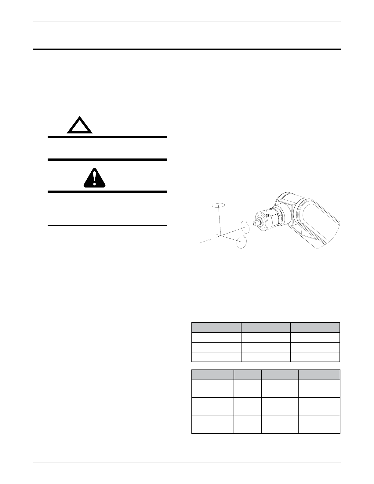
2.03 Introduction
The Tweco® Robotics Robotic Deflection Mount – “RDM2000” series — is a safety device designed to act as a
switch between the conductor tube and the robot arm. The
internal switch mechanism is activated when a collision
is detected in any direction.
How the Deflection Mount Works
When there is a collision between the conductor tube and
fixture/part, the conductor tube will move in the direction
with the deflection mount shaft. When this happens, one
or more of the three switches located inside of the mount
assembly will be activated. This activates the E-Stop
circuit, which is normally in the closed position, thus
stopping the travel of the robot arm.
The deflection mount detects motion in any direction,
whether it is in the Z-axis (head on), a side load, or a
torsional load.
2.02 Receipt of Equipment
When you receive the equipment, check it against the
invoice to make sure it is complete and inspect the
equipment for possible damage due to shipping. If there is
any damage, notify the carrier immediately to file a claim.
Furnish complete information concerning damage claims
or shipping errors to the location in your area listed in the
inside back cover of this manual. Include a full description
of the parts in error.
If you want additional or replacement copies of this CD,
please contact Tweco® Robotics at the address and phone
number in your area listed on the inside back cover of this
manual. Include the Manual number (from page i) and
CD part number: 64-2601.
The RDM-2000 series deflection mounts are offered in
three models, allowing you to choose the best spring rate
depending upon the specific application requirements.
In addition to the three spring rates, the mounts come
standard with an air assist feature. This allows the robot
technician to increase the break - away pressure for any
of the forces. Refer to Tables 1 through 3 for more detail,
located on in Section 3, page 3-8.
Part No. Stock No. Description
RDM-2000-S 3500-1155 Light Duty
RDM-2000-M 3500-1156 Medium Duty
RDM-2000-H 3500-1157 Heavy Duty
Part No. Fz Mx/My Mz
RDM-2000-S 267 N
(60#)
RDM-2000-M 444 N
(100#)
RDM-2000-H 662 N
(140#)
18 Nm (160
In-lbs)
27 Nm (245
In-lbs)
28 Nm (250
In-lbs)
Ca. 15Nm
(130 In-lbs)
Ca. 25 Nm
(220 In-lbs)
Ca. 26 Nm
(230 In-lbs)
SM-RDM-2000
INTRODUCTION AND DESCRIPTION
2-4
Page 9

Robotic Deflection Mount
6
5
9
4
3
2
1
7
8
The RDM-2000 series deflection mounts come standard
with the items shown in Figure 1. Before starting the
installation, please read and understand the installation
procedure outlined in this manual.
NOTE
RDM adapter plate used to adapt the RDM
mount to the robot arm are sold separately.
Refer to Section 4, pages 10-14, to ensure the
RDM adapter plate is correct for your specific
robot.
Figure 1: Packaged RDM-2000 Mount
Item No. Description Qty.
1 RDM-2000 Deflection Mount Assembly 1
2 E-Stop Cable Assembly 1
3 Rear Adapter Plate (Aluminum) 1
4 M6 x 1 x 16mm Flat Head Socket Cap Screw 5
5 4mm Hex Wrench 1
6 3 mm Hex Wrench 1
7 3/16” x 3/16” x ½” Long Keystock 1
8 Air Fitting (Accepts 5/32” tubing) 1
9 M4 x 60mm Socket Head Cap Screws 6
SM-RDM-20000
2-5
INTRODUCTION AND DESCRIPTION
Page 10
Robotic Deflection Mount
SECTION 3:
INSTALLATION AND OPERATION
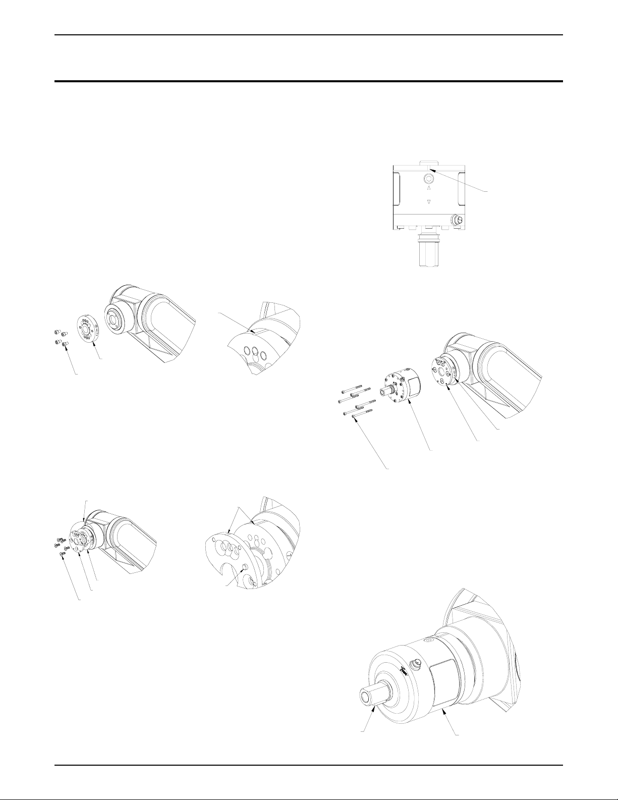
3.01 Installation
1. Remove the RDM mount and the other accessories
from the carton. Check to ensure all the items shown
in Figure 1 are located and identified. If any of the
component parts are missing, please notify the
Welding Distributor or Tweco Products customer
service department (1-800-426-1888).
2. Identify and set the “HOME
3. Located on the outer diameter of the RDM adapter
plate is a machined line indicating “HOME” position.
Position this line to the “HOME” position on the robot
arm. Using a 5mm allen wrench, insert and tighten
the socket head cap screws furnished with the RDM
adapter plate. Refer to Figure 2.
” position on the robot.
7. Locate the engraved arrows on the side of the mount.
Align the arrows with the “HOME” line on the rear adapter
plate and place the mount against the plate. The brass
locating pin protruding out from the rear mounting plate
should help locate and position the RDM mount into the
correct position. Refer to Figure 4.
HOME
POSITION
Figure 4: Arrows On RDM Mount
ALIGN WITH “HOME“
POSITION ON ROBOT
ARM
RDM ADAPTER
PLATE
SOCKET HEAD CAP SCREWS
Figure 2: RDM Adapter To Robot Arm
4. Position and secure the aluminum rear adapter plate
to the RDM adapter plate using the M6 x 1 x 16mm
flat head cap screws. This plate also has a machined
line indicating “HOME” position. Align this to the RDM
adapter plate machined line. Refer to Figure 3.
SEE DETAIL B
RDM ADAPTER PLATE
REAR MOUNTING PLATE
FLAT HEAD CAP SCREWS
ALIGN
LOCATING
PIN
DETAIL B
Figure 3: Rear Mounting Plate
8. Using the 3mm Allen wrench, supplied from the
factory, tighten the M4 x 60mm socket head cap screw
to the rear adapter plate. Refer to Figure 5.
RDM ADAPTER PLATE
REAR ADAPTER PLATE
RDM-2000 DEFLECTION MOUNT
M4 X 60MM SOCKET HEAD CAP SCREWS
Figure 5: Mounting of RDM Mount
9. Slide the black protective cover back over the mount
shaft and place the 3/16” key stock into the machined
slot on the mount shaft. Refer to Figure 6.
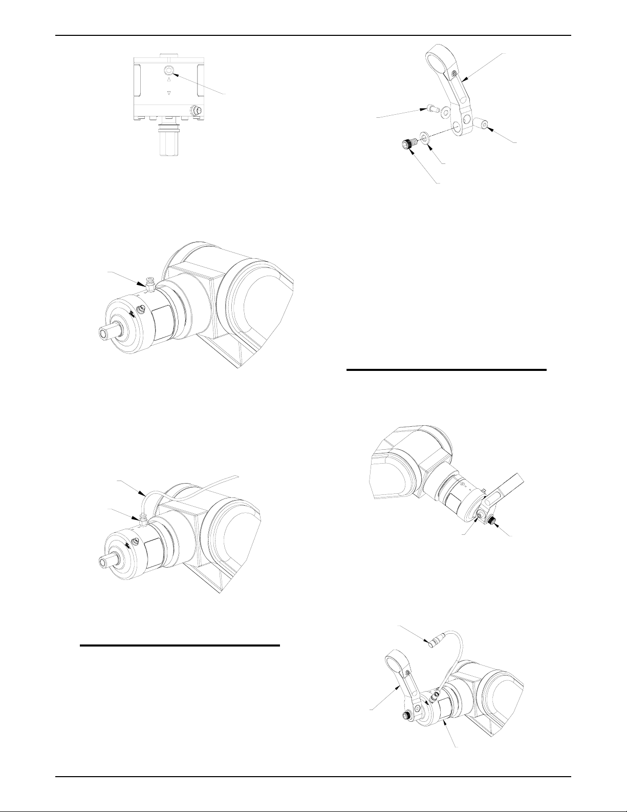
10. If the air assist feature will be used, remove the 1/8” NPT
plug from the side of the mount. Refer to Figure 7.
5. Remove the 7/16”-20 socket head cap screw and flat
washer from the mount shaft on the RDM mount and
set aside.
6. Slide the black protective cover away from the RDM
mount. Insert the M4 x 60mm socket head cap screws
into the holes on the front cover plate.
key
rdm deflection mount
Figure 6: Key Stock Location
SM-RDM-2000
INSTALLATION AND OPERATION
3-6
Page 11
Robotic Deflection Mount
RDM MOUNTING
ARM
AIR ASSIST PORT
(1/8 NPT)
Figure 7: Air Assist Port
11. Thread the air fitting supplied from the factory, into
the RDM mount and tighten. The fitting will accept
5/32” tubing, (not supplied), from a compressed air
regulator. Refer to Figure 8.
AIR FITTING
Figure 8: Installation of Air Fitting
12. To provide the air assist, a 5/32” (3,97mm) tubing
coming out of the air fitting should be extended back
to the feeder or robot base where it is attached to an
adjustable air line regulator. Refer to Section 3.02 page
10 for more detail on the air assist option.
5/16-18 SOCKET
HEAD CAP
SCREW
& WASHER
WEDGE PIN
7/16 FLAT WASHER
7/16-20 SOCKET HEAD CAP SCREW
Figure 10: Exploded View of RDM Mounting Arm &
Mounting Screws
15. Align the machined key slot on the mounting arm with
the 3/16” key stock on the RDM mount shaft. Slide the
mounting arm over the mount shaft.
16. Tighten the 5/16”-18 socket head cap screw until the
wedge pin is drawn into contact against the shaft on the
RDM mount. This connection must be wrench tight.
17. Install the 7/16-20 socket head cap screw and 7/16” flat
washer removed in Step 5 onto the RDM mount and
secure. Refer to Figure 10.
NOTE
The centerline of the RDM mount arm should
be inline with the engraved arrows on the RDM
mount when in the “HOME” position.
5/32” TUBING
AIR FITTING
Figure 9: Air Tubing To Air Line Regulator
NOTE
It’s recommended that the air assist feature
be installed in a manner that a continuous
air pressure is supplied to the mount during
operation.
13. The RDM mount is now ready for the RDM mounting
arm to be secured into position.
14. Loosen the 5/16”-18 socket head cap screw that is
threaded into the wedge pin of the mounting hardware
of the RDM arm. Refer to Figure 10.
7/16”-20
5/16-18 SOCKET HEAD
CAP SCREW & WASHER
SOCKET
HEAD CAP
SCREW
Figure 11: Mounting Arm Screws Used to Secure Arm
to Mount
18. Attach the E-Stop cable assembly, supplied from the
factory, to the RDM mount. Refer to Figure 11.
E-STOP CABLE
MOUNT ARM
RDM DEFLECTION MOUNT
Figure 12: E-stop Cable Connection
SM-RDM-20000
3-7
INSTALLATION AND OPERATION
Page 12

Robotic Deflection Mount
F
z
M
y
M
x
M
z
0
50
100
150
200
250
300
350
400
450
500
0 10 20 30 40 50 60 70 80 90 10
Air Pressure (PSI)
Mx,My & Mz ( in-lbs)
0
50
100
150
200
250
300
350
400
450
500
Fz (lbs)
0
50
100
150
200
250
300
350
400
450
500
0 10 20 30 40 50 60 70 80 90 10
Air Pressure (PSI)
Air Pressure (PSI)
Mx,My & Mz (in-lbs)
0
50
100
150
200
250
300
350
400
450
500
Fz (lbs)
0
50
100
150
200
250
300
350
400
450
500
0 10 20 30 40 50 60 70 80 90 10
Mx,My & Mz (in-lbs)
0
50
100
150
200
250
300
350
400
450
500
Fz (lbs)
19. The installation of the RDM mount arm is now complete and is ready to accept the torch and cable assembly. Follow the
outlined procedure found in the Installation Guide provided with the Torch and Cable Assembly.
3.02 Air Assist Feature
The addition of air pressure to the RDM mount during operation will increase the force that would be required to
activate the switches within the mount causing the robot arm to stop.Refer to Figure 12 and Tables 1 through 3 for
further detail on air pressure versus force (Mx, My, and Mz lb-in) and (Fz – lb).
Figure 12: RDM Mount Motion with Air Assist
Table 1: Light Deflection Mount Table 2: Medium Deflection Mount
Fz
Fz
Table 1: Heavy Deflection Mount
SM-RDM-2000
INSTALLATION AND OPERATION
3-8
Page 13

3.03 Wiring Diagram
!
The RDM-2000 Series deflection mount uses a single
normally closed, switch to determine the deflection
breakaway. Since the circuit is normally closed, the
emergency stop relay will be on during operation. If the
power is lost, a wire breaks, or if there is a collision, the
circuit will break telling the robot to stop. (If a normally
open circuit is desired, use the white wire instead of the
brown.) Refer to the diagram below.
RDM 2000 SERIES
DEFLECTION MOUNT
NORMAL OPERATION
ROBOT CONTROL
SHOCK SENSOR
CIRCUIT
BROWN
NORMALLY CLOSED
Robotic Deflection Mount
COMMON
OPTIONAL
NORMALLY
OPEN CIRCUIT
GREEN
WHITE
NORMALLY OPEN
COMMON
3.04 Maintenance
The RDM-2000 Series deflection mount is designed to
operate in the most rugged industrial environments with
a minimum of maintenance. We recommend that the user
does not attempt to disassemble the mount other than
those steps required to attach the unit to the robot arm.
WARNING
DO NOT ATTEMPT TO OPEN THE RDM DEFLECTION
MOUNT. THE POWERFUL COMPRESSED SPRING
CONTAINED WITHIN CAN CAUSE INJURY IF
DISASSEMBLED IMPROPERLY. IT IS RECOMMENDED
THAT THE RDM DEFLECTION MOUNTS BE RETURNED
TO THE FACTORY FOR REPAIRS.
Figure 13: Exploded View of Internal Components
SM-RDM-20000
3-9
INSTALLATION AND OPERATION
Page 14

Robotic Deflection Mount
4
2
1
3
C
B°
Ø A
Ø
D
RDM-AP-X
C
B°
Ø D
Ø
A
RDM-AP-X
T
YPE A
TY
P
E
B
REPLACEMENT PARTS
SECTION 4:
Replacement Parts for RDM-2000
Item No. Part No. Stock No. Description
1 RDM-2000-B 3500-1197 RDM-2000 Deflection Mount Assembly
2 RDM-2000-JC 3044-1842 E-Stop Cable Assembly - 18”
RDM-2000-EC
3 RDM-2000-AP 3500-1174 Rear Adapter Plate (Aluminum)
4 AF532-18NPT-S 3500-1385 Air Fitting (Accepts 5/32” tubing)
Adapter Plates for RDM-2000
(457.2mm)***
3500-1172 E-Stop Cable Assembly – 20’ (6,10m)
*** Standard on all RDM Deflection Mounts
Tweco Robotics offers many different adapter plates to use
with the RDM-2000 Series deflection mount. The adapter
plate acts as an additional insulator to protect the robot
arm as well as a mechanical breakaway in the event the
switching does not stop the robot or peripheral motion.
The following table will aid in determining the proper
adapter plate required too install the deflection mount to
your robot arm.
SM-RDM-2000
REPLACEMENT PARTS
4-10
Page 15

Robotic Deflection Mount
Robot Type Robot
Model No.
AdapterPart
No.
AdapterStock
No. Type Ø A B° C Ø D
ABB IRB-6 RDM-AP-8 3500-1147 A 1.575”
40,01mm
RDM-AP-2 3500-1141 A 1.575”
40,01mm
IRB 1500 RDM-AP-8 3500-1147 A 1.575”
40,01mm
RDM-AP-2 3500-1141 A 1.575”
40,01mm
IRB 2000 RDM-AP-8 3500-1147 A 1.575”
40,01mm
RDM-AP-2 3500-1141 A 1.575”
40,01mm
IRB 1400 RDM-AP-8 3500-1147 A 1.575”
40,01mm
RDM-AP-2 3500-1141 A 1.575”
40,01mm
IRB 2400 RDM-AP-8 3500-1147 A 1.575”
40,01mm
RDM-AP-2 3500-1141 A 1.575”
40,01mm
IRB 240L RDM-AP-8 3500-1147 A 1.575”
40,01mm
RDM-AP-2 3500-1141 A 1.575”
40,01mm
ASEA ALL
MODELS
RDM-AP-8 3500-1147 A 1.575”
40,01mm
RDM-AP-2 3500-1141 A 1.575”
40,01mm
ESAB 1500 RDM-AP-8 3500-1147 A 1.575”
40,01mm
RDM-AP-2 3500-1141 A 1.575”
40,01mm
2000 RDM-AP-8 3500-1147 A 1.575”
40,01mm
RDM-AP-2 3500-1141 A 1.575”
40,01mm
FANUC ARC MATE
100/S6
RDM-AP-8 3500-1147 A 1.575”
40,01mm
RDM-AP-2 3500-1141 A 1.575”
40,01mm
ARC MATE
120
RDM-AP-8 3500-1147 A 1.575”
40,01mm
RDM-AP-2 3500-1141 A 1.575”
40,01mm
45° .650”
16,51mm
22.5° .525”
13,34mm
45 .650”
16,51mm
22.5° .525”
13,34mm
45° .650”
16,51mm
22.5° .525”
13,34mm
45° .650”
16,51mm
22.5° .525”
13,34mm
45° .650”
16,51mm
22.5° .525”
13,34mm
45° .650”
16,51mm
22.5° .525”
13,34mm
45° .650”
16,51mm
22.5° .525”
13,34mm
45° .650”
16,51mm
22.5° .525”
13,34mm
45° .650”
16,51mm
22.5° .525”
13,34mm
45° .650”
16,51mm
22.5° .525”
13,34mm
45° .650”
16,51mm
22.5° .525”
13,34mm
1.937”
49,20mm
1.937”
49,20mm
1.937”
49,20mm
1.937”
49,20mm
1.937”
49,20mm
1.937”
49,20mm
1.937”
49,20mm
1.937”
49,20mm
1.937”
49,20mm
1.937”
49,20mm
1.937”
49,20mm
1.937”
49,20mm
1.937”
49,20mm
1.937”
49,20mm
1.937”
49,20mm
1.937”
49,20mm
1.937”
49,20mm
1.937”
49,20mm
1.937”
49,20mm
1.937”
49,20mm
1.937”
49,20mm
1.937”
49,20mm
SM-RDM-20000
4-11
REPLACEMENT PARTS
Page 16

Robotic Deflection Mount
Robot
Type
FANUC ARC MATE
Robot Model
No.
120/S/12
AdapterPart
No.
AdapterStock
No. Type Ø A B° C Ø D
RDM-AP-8 3500-1147 A 1.575”
40,01mm
RDM-AP-2 3500-1141 A 1.575”
40,01mm
ARC MATE
100/I
RDM-AP-8 3500-1147 A 1.575”
40,01mm
RDM-AP-2 3500-1141 A 1.575”
40,01mm
ARC MATE JR
SR.S-10
ARC MATE JR
S/5
LR MATE
100 1
RDM-AP-4 3500-1143 A 1.968”
49,99mm
RDM-AP-4 3500-1143 A 1.968”
49,99mm
RDM-AP-16 3500-1120 A 1.240”
31,50MM
50 iL RDM-AP-24 3500-1181 B 1.240”
31,50mm
Arc Mate
100iB, M-6iB,
RDM-AP-8 3500-1147 A 1.575”
40,01
100ib/6S
HITACHI 5430 RDM-AP-4 3500-1143 A 1.968”
49,99mm
MR 6060 RDM-AP-6 3500-1145 B 1.575”
40,01mm
MR 6100 RDM-AP-6 3500-1145 B 1.575”
40,01mm
KAWASAKI FS010 RDM-AP-25 3500-1118 B 2.480”
62,99mm
FS010L RDM-AP-25 3500-1118 B 2.480”
62,99mm
JS6 RDM-AP-6 3500-1145 B 1.575”
40,01mm
SJ10 RDM-AP-6 3500-1145 B 1.575”
40,01mm
KUKA KR6 RDM-AP-17 3500-1123 B 1.968”
49,99mm
KR150 RDM-AP-17 3500-1123 B 1.968”
49,99mm
KR3015 RDM-AP-17 3500-1123 B 1.968”
49,99mm
MILLER MRV-6 RDM-AP-8 3500-1147 A 1.575”
40,01mm
RDM-AP-2 3500-1141 A 1.575”
40,01mm
MRV-2000 RDM-AP-8 3500-1147 A 1.575”
40,01mm
RDM-AP-2 3500-1141 A 1.575”
40,01mm
MRV-2300 RDM-AP-8 3500-1147 A 1.575”
40,01mm
RDM-AP-2 3500-1141 A 1.575”
40,01mm
45° .650”
16,51mm
22.5° .525”
13,34mm
45° .650”
16,51mm
22.5° .525”
13,34mm
45° .525”
13,34mm
45° .525”
13,34mm
45° .650”
16,51mm
45° .550”
13,97mm
45° .650”
16,51mm
45° .525”
13,34mm
45° .525”
13,34mm
45° .525”
13,34mm
45° .525”
13,34mm
45° .525”
13,34mm
45° .525”
13,34mm
45° .525”
13,34mm
45° .650”
16,51mm
45° .650”
16,51mm
45° .650”
16,51mm
45° .650”
16,51mm
22.5° .525”
13,34mm
45° .650”
16,51mm
22.5° .525”
13,34mm
45° .650”
16,51mm
22.5° .525”
13,34mm
1.937”
49,20mm
1.937”
49,20mm
1.937”
49,20mm
1.937”
49,20mm
1.263”
32,08mm
1.263”
32,08mm
1.973”
49,20mm
.787”
19,99mm
1.937”
49,20mm
1.263”
32,08mm
.981”
24,92mm
.981”
24,92mm
1.571”
39,90mm
1.571”
39,90mm
.981”
24,92mm
.981”
24,92mm
1.236”
31,39mm
1.236”
31,39mm
1.236”
31,39mm
1.937”
49,20mm
1.937”
49,20mm
1.937”
49,20mm
1.937”
49,20mm
1.937”
49,20mm
1.937”
49,20mm
SM-RDM-2000
REPLACEMENT PARTS
4-12
Page 17

Robotic Deflection Mount
Robot Type Robot
Model No.
AdapterPart
No.
AdapterStock
No. Type Ø A B° C Ø D
MILLER MR-5 RDM-AP-7 3500-1146 A 1.265”
32,13mm
MR-1000 RDM-AP-7 3500-1146 A 1.265”
32,13mm
MRH RDM-AP-7 3500-1146 A 1.265”
32,13mm
MRK5 RDM-AP-7 3500-1146 A 1.265”
32,13mm
MOTOMAN SV-3 RDM-AP-24 3500-1181 B 1.240”
31,50mm
K5 RDM-AP-8 3500-1147 A 1.575”
40,01mm
RDM-AP-2 3500-1141 A 1.575”
40,01mm
K6 RDM-AP-8 3500-1147 A 1.575”
40,01mm
RDM-AP-2 3500-1141 A 1.575”
40,01mm
K10 RDM-AP-8 3500-1147 A 1.575”
40,01mm
45° .650”
16,51mm
45° .650”
16,51mm
45° .650”
16,51mm
45° .650”
16,51mm
45° .550”
13,97mm
45° .650”
16,51mm
22.5° .525”
13,34mm
45° .650”
16,51mm
22.5° .525”
13,34mm
45° .650”
16,51mm
1.579”
40,11mm
1.579”
40,11mm
1.579”
40,11mm
1.579”
40,11mm
.787”
19,99mm
1.937”
49,20mm
1.937”
49,20mm
1.937”
49,20mm
1.937”
49,20mm
1.937”
49,20mm
RDM-AP-2 3500-1141 A 1.575”
40,01mm
SK SERIES RDM-AP-8 3500-1147 A 1.575”
40,01mm
RDM-AP-2 3500-1141 A 1.575”
40,01mm
SUPER K RDM-AP-8 3500-1147 A 1.575”
40,01mm
RDM-AP-2 3500-1141 A 1.575”
40,01mm
UP6,
UP20,
RDM-AP-27 3500-1191 A 1.575”
40,01mm
UP20-6 &
UP20M
L SERIES RDM-AP-9 3500-1148 B 2.047”
51,99mm
NACHI SC15 RDM-AP-11 3500-1115 A 1.890”
48,01mm
7603 RDM-AP-10 3500-1149 A 2.047”
51,99mm
SC06 RDM-AP-26 3500-1114 B 1.890”
48,01mm
22.5° .525”
13,34mm
45° .650”
16,51mm
22.5° .525”
13,34mm
45° .650”
16,51mm
22.5° .525”
13,34mm
45° .650”
16,51mm
22.5° .525”
13,34mm
25° .525”
13,34mm
22.5° .525”
13,34mm
30° .525”
13,34mm
1.937”
49,20mm
1.937”
49,20mm
1.937”
49,20mm
1.937”
49,20mm
1.937”
49,20mm
1.937”
49,20mm
1.569”
39,85mm
.949”
24,10mm
1.697”
43,10mm
.561”
14,25mm
OTC
DIAHEN
SM-RDM-20000
DR 4000 RDM-AP-8 3500-1147 A 1.575”
40,01mm
RDM-AP-2 3500-1141 A 1.575”
40,01mm
4-13
45° .650”
16,51mm
22.5° .525”
13,34mm
1.937”
49,20mm
1.937”
49,20mm
REPLACEMENT PARTS
Page 18

Robotic Deflection Mount
Robot Type Robot
Model No.
OTC
DR 500 RDM-AP-8 3500-1147 A 1.575”
DIAHEN
AdapterPart
No.
AdapterStock
No. Type Ø A B° C Ø D
40,01mm
RDM-AP-2 3500-1141 A 1.575”
40,01mm
DR 4200 RDM-AP-8 3500-1147 A 1.575”
40,01mm
RDM-AP-2 3500-1141 A 1.575”
40,01mm
DR 3000 RDM-AP-7 3500-1146 A 1.265”
32,13mm
PANASONIC AW5A RDM-AP-12 3500-1116 B 1.968”
49,99mm
AW6A RDM-AP-12 3500-1116 B 1.968”
49,99mm
AW10A RDM-AP-12 3500-1116 B 1.968”
49,99mm
AW5C RDM-AP-12 3500-1116 B 1.968”
49,99mm
AW6AL RDM-AP-12 3500-1116 B 1.968”
49,99mm
VR 005 RDM-AP-12 3500-1116 B 1.968”
49,99mm
VR 006 RDM-AP-12 3500-1116 B 1.968”
49,99mm
VR 006L RDM-AP-12 3500-1116 B 1.968”
49,99mm
VR 008 RDM-AP-12 3500-1116 B 1.968”
49,99mm
VR 16 RDM-AP-12 3500-1116 B 1.968”
49,99mm
REIS RV6 RDM-AP-17 3500-1123 B 1.968”
49,99mm
RV6L RDM-AP-17 3500-1123 B 1.968”
49,99mm
RV-16 RDM-AP-20 3500-1177 B 2.480”
62,99mm
RH30-16 RDM-AP-20 3500-1177 B 2.480”
62,99mm
STAUBLI RX90 RDM-AP-8 3500-1147 A 1.575”
40,01mm
RDM-AP-2 3500-1141 A 1.575”
40,01mm
45° .650”
16,51mm
22.5° .525”
13,34mm
45° .650”
16,51mm
22.5° .525”
13,34mm
45° .650”
16,51mm
45° .525”
13,34mm
45° .525”
13,34mm
45° .525”
13,34mm
45° .525”
13,34mm
45° .525”
13,34mm
45° .525”
13,34mm
45° .525”
13,34mm
45° .525”
13,34mm
45° .525”
13,34mm
45° .525”
13,34mm
45° .650”
16,51mm
45° .650”
16,51mm
45° .650”
16,51mm
45° .650”
16,51mm
45° .650”
16,51mm
22.5° .525”
13,34mm
1.937”
49,20mm
1.937”
49,20mm
1.937”
49,20mm
1.937”
49,20mm
1.579”
40,11mm
1.571”
39,90mm
1.571”
39,90mm
1.571”
39,90mm
1.571”
39,90mm
1.571”
39,90mm
1.571”
39,90mm
1.571”
39,90mm
1.571”
39,90mm
1.571”
39,90mm
1.571”
39,90mm
1.236”
31,39mm
1.236”
31,39mm
1.888”
47,96mm
1.888”
47,96mm
1.937”
49,20mm
1.937”
49,20mm
SM-RDM-2000
REPLACEMENT PARTS
4-14
Page 19

Robotic Deflection Mount
STATEMENT OF WARRANTY
LIMITED WARRANTY: THERMADYNE® warrants that its products will be free of defects in workmanship or material.
Should any failure to conform to this warranty appear within the time period applicable to the THERMADYNE products
as stated below, THERMADYNE shall, upon notification thereof and substantiation that the product has been stored,
installed, operated, and maintained in accordance with THERMADYNE’s specifications, instructions, recommendations
and recognized standard industry practice, and not subject to misuse, repair, neglect, alteration, or accident, correct
such defects by suitable repair or replacement, at THERMADYNE’s sole option, of any components or parts of the
product determined by THERMADYNE to be defective.
THIS WARRANTY IS EXCLUSIVE AND IS IN LIEU OF ALL OTHER WARRANTIES, EXPRESS OR IMPLIED, INCLUDING
ANY WARRANTY OF MERCHANTABILITY OR FITNESS FOR A PARTICULAR PURPOSE.
LIMITATION OF LIABILITY:
damages, such as, but not limited to, damage or loss of purchased or replacement goods, or claims of customers of
distributor (hereinafter the “Purchaser”) for service interruption. The remedies of the Purchaser set forth herein are
exclusive and the liability of THERMADYNE with respect to any contract, or anything done in connection therewith such
as the performance or breach thereof, or from the manufacture, sale, delivery, resale, or use of any goods covered by or
furnished by THERMADYNE whether arising out of contract, negligence, strict tort, or under any warranty, or otherwise,
shall not, except as expressly provided herein, exceed the price of the goods upon which such liability is based.
THIS WARRANTY BECOMES INVALID IF REPLACEMENT PARTS OR ACCESSORIES ARE USED WHICH MAY IMPAIR
THE SAFETY OR PERFORMANCE OF ANY THERMADYNE PRODUCT.
THIS WARRANTY IS INVALID IF THE PRODUCT IS SOLD BY NON-AUTHORIZED PERSONS.
This warranty is effective for the time stated in the Warranty Schedule beginning on the date that the authorized
distributor delivers the products to the Purchaser.
Warranty repairs or replacement claims under this limited warranty must be submitted by an authorized THERMADYNE
repair facility within thirty (30) days of the repair. No transportation costs of any kind will be paid under this warranty.
Transportation charges to send products to an authorized warranty repair facility shall be the responsibility of the
Purchaser. All returned goods shall be at the Purchaser’s risk and expense. This warranty supersedes all previous
THERMADYNE warranties.
THERMADYNE shall not under any circumstances be liable for special or consequential
SM-RDM-20000
5-15
Page 20

WARRANTY SCHEDULE
The warranty is effective below for the time stated in the Warranty Schedule beginning on the date that the authorized
distributor delivers the products to the purchaser. THERMADYNE® reserves the right to request documented evidence
of date of purchase.
Engine Driven Welders Parts / Labor
Original Main Power Stators and Inductors 3 years / 3 years
Original Main Power Rectifiers, Control P.C. Boards 3 years / 3 years
All Other Original Circuits and Components Including, but not Limited to, Relays, Switches, Contactors, Solenoids, Fans, Power Switch Semi-Conductors 1 year / 1 year
Engines and Associated Components are NOT Warranted by Thermal Arc®, Although Most are Warranted by the Engine Manufacturer. SEE THE ENGINE
MANUFACTURERS’ WARRANTY FOR DETAILS.
Fabricator® 131, 181, 190, 210, 251, 281; Fabstar® 4030; PowerMaster® 350, 350P, 500, 500P; Excel-Arc® 6045; Wire Feeders: Ultrafeed®, Porta-feed®
Original Main Power Transformer and Inductor 5 years / 3 years
Original Main Power Rectifiers, Control P.C. Boards, Power Switch Semi-Conductors 3 years / 3 years
All Other Original Circuits and Components Including, but not Limited to, Relays, Switches, Contactors, Solenoids, Fans, Electric Motors 1 year / 1 year
160TS, 300TS, 400TS, 185AC/DC, 200AC/DC, 300AC/DC, 400GTSW, 400MST, 300MST, 400MSTP
Original Main Power Magnetics 5 years / 3 years
Original Main Power Rectifiers, Control P.C. Boards, Power Switch Semi-Conductors 3 years / 3 years
All Other Original Circuits and Components Including, but not Limited to, Relays, Switches, Contactors, Solenoids, Fans, Electric Motors 1 year / 1 year
Original Main Power Magnetics 5 years / 3 years
Original Main Power Rectifiers, Control P.C. Boards, Power Switch Semi-Conductors 3 years / 3 years
Welding Console, Weld Controller, Weld Timer 3 years / 3 years
All Other Original Circuits and Components Including, but not Limited to, Relays, Switches, Contactors, Solenoids, Fans, Electric Motors, Coolant Recirculators 1 year / 1 year
Original Main Power Magnetics 1 year / 1 year
Original Main Power Rectifiers, Control P.C. Boards 1 year / 1 year
All Other Original Circuits and Components Including, but not Limited to, Relays, Switches, Contactors, Solenoids, Fans, Power Switch Semi-Conductors 1 year / 1 year
Original Main Power Magnetics 5 years / 3 years
Original Main Power Rectifiers, Control P.C. Boards 3 years / 3 years
All Other Original Circuits and Components Including, but not Limited to, Relays, Switches, Contactors, Solenoids, Fans, Power Switch Semi-Conductors 1 year / 1 year
Water Recirculators 1 year / 1 year
Plasma Welding Torches 180 days / 180 days
Gas Regulators (Supplied with Power Sources) 180 days / NA
MIG and TIG Torches (Supplied with Power Sources) 90 days / NA
Replacement Repair Parts 90 days / NA
MIG, TIG and Plasma Welding Torch Consumable Items NA / NA
Victor® Professional 5 years / NA
Oxygen Conservers 2 years / NA
Aluminum Cylinders Lifetime / NA
Cutting Machine Motors 1 year / NA
HP&I Brass Regulators/Manifolds 2 years / NA
HP&I Stainless Regulators/Manifolds 1 year / NA
HP&I Corrosive Gas Regulators/Manifolds 90 days / NA
TurboTorch® 3 years / NA
CutSkill® 2 years / NA
Steel Cylinders 1 year / NA
Victor Medical 6 years / NA
Victor VSP 2 years / NA
Firepower® MIG Welders 5-2-1 years / NA
Transformers 5 years / NA
Parts Used in Rental Applications 1 year from date sold by seller to authorized
Arcair® N6000 90 days / NA
Eliminator® Spool and Pull Guns 90 days / NA
Robotic Deflection Mounts 90 days / NA
QRM-100 Anti-Spatter Applicator 90 days / NA
TC and TCV Water Coolers 1 year / NA
TSC-96 Smoke Collector 1 year / NA
ESG-1, EPG-CR1, EPG-CR2 Control Boxes for Eliminator Spool & Pull Guns 1 year / NA
QRC-2000 Nozzle Cleaning Stations 1 year / 1 year
All other products 30 days from date purchaser purchases from seller. 30 days / NA
Automated Plasma 2 years / 1 year
CutMaster™ 3 years / 3 years
PakMaster® XL PLUS 3 years / 1 year
Drag-Gun® 1 year / 1 year
Drag-Gun Plus 2 years / 1 year
Torches 1 year / 1 year
Consoles, Control Equipment, Heat Exchangers and Accessory Equipment 1 year / 1 year
GTAW (TIG) & Multi-process Inverter Welding Equipment Parts / Labor
Scout®, Raider®, Explorer™
See the Engine Manufacturers’ Warranty
GMAW/FCAW (MIG) Welding Equipment Parts / Labor
Plasma Welding Equipment Parts / Labor
Ultima® 150
SMAW (Stick) Welding Equipment Parts / Labor
Dragster™ 85
160S, 300S, 400S
General Arc Equipment Parts / Labor
Gas Welding and Cutting Equipment Parts / Labor
MIG Torches and Arc Accessories Parts / Labor
Plasma Cutting Systems Parts / Labor
for Details
distributor
Page 21

GLOBAL CUSTOMER SERVICE CONTACT INFORMATION
Thermadyne USA
2800 Airport Road
Denton, TX 76207 USA
Telephone: (1) 800-535-1888
Fax: (1) 800-535-0557
Thermadyne Canada
2070 Wyecroft Road
Oakville, Ontario
Canada, L6L5V6
Telephone: (1) 905-827-9777
Fax: (1) 905-827-9797
Thermadyne Europe
Europe Building
Chorley North Industrial Park
Chorley, Lancashire
England, PR6 7Bx
Telephone: (44) 1257-261755
Fax: (44) 1257-224800
Thermadyne Asia Sdn Bhd
Lot 151, Jalan Industri 3/5A
Rawang Integrated Industrial Park - Jln Batu Arang
48000 Rawang Selangor Darul Ehsan
West Malaysia
Telephone: 603+ 6092 2988
Fax : 603+ 6092 1085
Cigweld Australia
71 Gower Street
Preston, Victoria
Australia, 3072
Telephone: 1300-654-674
Fax: 613+ 9474-7391
Thermadyne Italy
OCIM, S.r.L.
Via Benaco, 3
20098 S. Giuliano
Milan, Italy
Tel: (39) 02-98 80320
Fax: (39) 02-98 281773
Thermadyne China
RM 102A
685 Ding Xi Rd
Chang Ning District
Shanghai, PR, 200052
Telephone: 86 21+6280-1273
Fax: 86 21+3226-0955
Thermadyne International
2070 Wyecroft Road
Oakville, Ontario
Canada, L6L5V6
Telephone: (1) 905-827-9777
Fax: (1) 905-827-9797
Page 22

World Headquarters
Thermadyne Holdings Corporation
Suite 300, 16052 Swingley Ridge Road
St. Louis, MO 63017
Telephone: (636) 728-3000
Fascimile: (636) 728-3010
www.thermadyne.com
 Loading...