

Page 1
82 Benning Street, West Lebanon, NH 03784 USA
(603) 298-5711 • www.thermal-dynamics.com
Manual 0-4736
Remote Arc Starter
Model RAS-1000,
Catalog # 3-9130
Installation Instructions
Scope
These instructions cover the RAS-1000 Remote Arc Starter.
Installation and service of this equipment is restricted to properly trained personnel; unqualified personnel are strictly cautioned against attempting repairs or adjustments not covered
in this manual, at the risk of voiding the Warranty.
Read these instructions thoroughly. A complete understanding of the characteristics and capabilities of this equipment will
assure the dependable operation for which it was designed.
General Description
The Remote Arc Starter is for use with Thermal Dynamics
UltraCut® Plasma Cutting Systems only. Do not use this
device with any other equipment.
The Remote Arc Starter generates a high - frequency pulse
to start a pilot arc for a Thermal Dynamics Plasma Cutting
Torch. The Remote Arc Starter includes a liquid cooled
coil. The power supply circulates coolant through the
Remote Arc Starter and through the torch. A wire harness
connected to the plasma power supply controls the operation of the Remote Arc Starter.
Installation
The Remote Arc Starter must be installed in a suitable location near the torch head. If the Arc Starter is mounted to
a gantry or any other support subject to motion or vibration, the installer must fasten the Arc Starter to the support
securely.
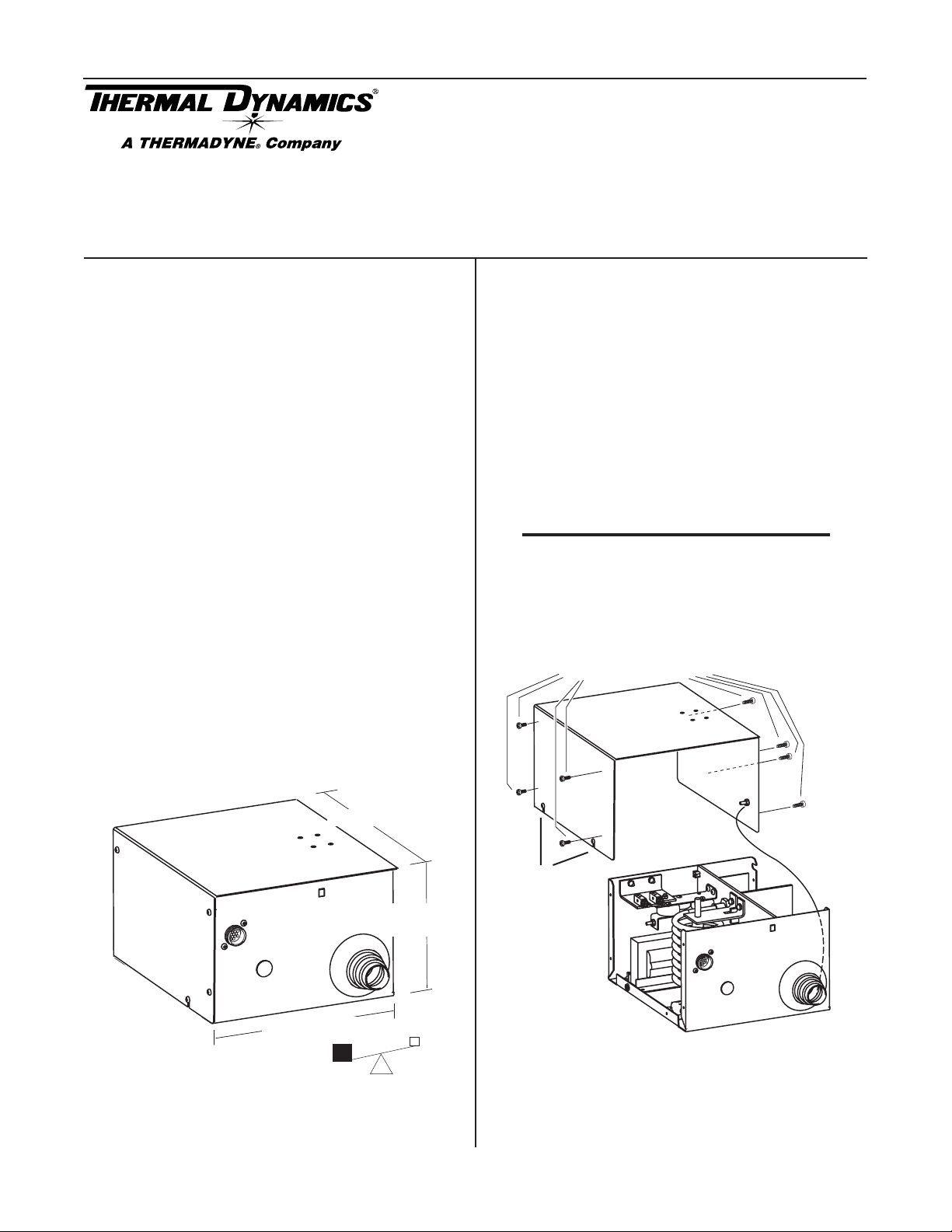
A. Preparation
1. Loosen, but do not remove, the lower screws securing
the cover to the Arc Starter. Remove the upper screws
securing the Cover Panel to the Arc Starter.
NOTE
A ground wire connects the cover to the Arc Starter
base. This wire must remain in place.
2. Remove the Cover Panel.
Upper screws (4 per side)
Cover
Specifications
12" / 305 mm
Ground Wire
Lower screws
7"
178 mm
10.5" / 267 mm
Art # A-04747
19 lb / 8.6 kg
Dimensions (Input Side Shown)
© 2005 Thermadyne Corp.
January 3, 2006 1 Manual 0-4736
Art # A-07029
3. Position the Arc Starter on a flat, horizontal, mounting surface.
Page 2
4. Use pre-drilled holes in at least two of the feet on
the bottom of the Arc Starter to secure the Arc Starter
to the mounting surface.
Minimum 2
Art # A-04749
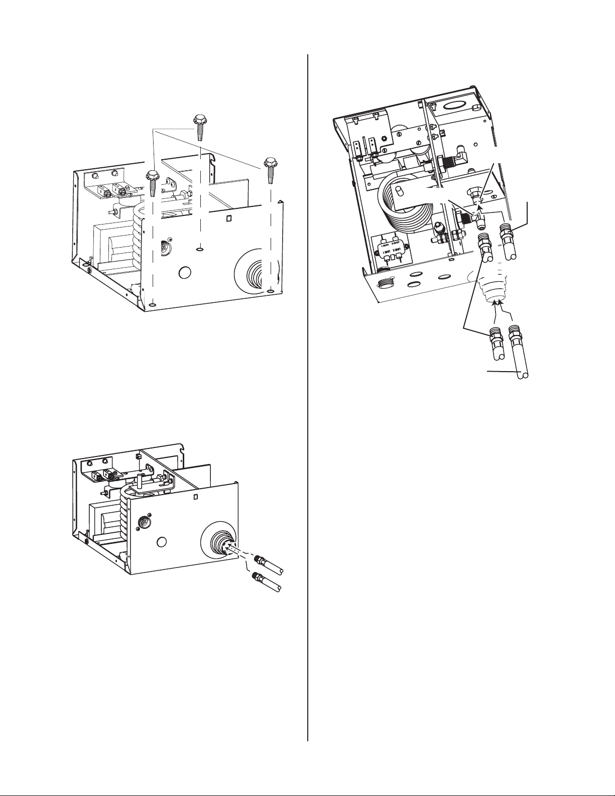
B. Input Connections
1. Refer to the illustrations. Make the following input connections to the Arc Starter.
Art # A-04751
Green
Coolant Supply (Green)
Coolant Return (Red)
Red
Coolant
Return
(Red)
• Coolant Supply and Return Hoses from power
supply. The fittings and hoses are color-coded;
Red for Return, Green for Supply.
Art # A-04750
Coolant Supply and Return Hoses
(from power supply)
• NEGATIVE Cable (from Power Supply rear
panel)
January 3, 2006 2 Manual 0-4736
Page 3

Art # A-04752
Art # A-04754
Negative Cable
from power supply
• PILOT Return Cable (from Power Supply rear
panel)
Negative Cable
(for > 150 Amps)
• CONTROL Cable from Power Supply rear
panel.
Art # A-04755
January 3, 2006 3 Manual 0-4736
Page 4

C. Output Connections
1. Refer to the illustrations. Make the following input connections to the Arc Starter.
• Pilot Return Cable (to Torch)
Inner Shield Lead
Pilot Lead
Art # A-04933
Inner Shield
Connection Detail
Pilot Lead
Connection Detail
January 3, 2006 4 Manual 0-4736
Page 5

• Coolant Supply and Return Hoses (to Torch)
Art # A-04757
Reinstall the Arc Starter Cover. Ensure that the ground
wire is not crimped between the cover and the base
assembly.
Upper screws (4 per side)
Coolant Return Fitting
(Tagged with Red)
Coolant Return (Red)
from Torch
Some items are removed
for clarity.
Coolant Supply Fitting
(Tagged with Green)
Coolant Supply
(Green) to Torch
Cover
Ground Wire
Lower screws
Art # A-07029
The Arc Starter must be grounded; the grounding ter-
minal is marked .
January 3, 2006 5 Manual 0-4736
Page 6

NOTE
Art # A-04758
Torch Leads
1 Nut and 1 Washer
Remain in Place
Ground Cable
• Use a clamp to secure the Torch Lead Shield
braid to the port on the Remote Arc Starter as
shown.
Every effort has been made to provide complete
and accurate information in this manual.
However, the publisher does not assume and
hereby disclaims any liability to any party for
any loss or damage caused by errors or omissions in this Manual, whether such errors result from negligence, accident, or any other
cause.
Art # A-04759
Torch Leads Shield
Shield Clamp
Coolant and Pilot Leads
to Torch Valve Assembly
This completes the installation of the Remote Arc
Starter.
January 3, 2006 6 Manual 0-4736
 Loading...