

Page 1

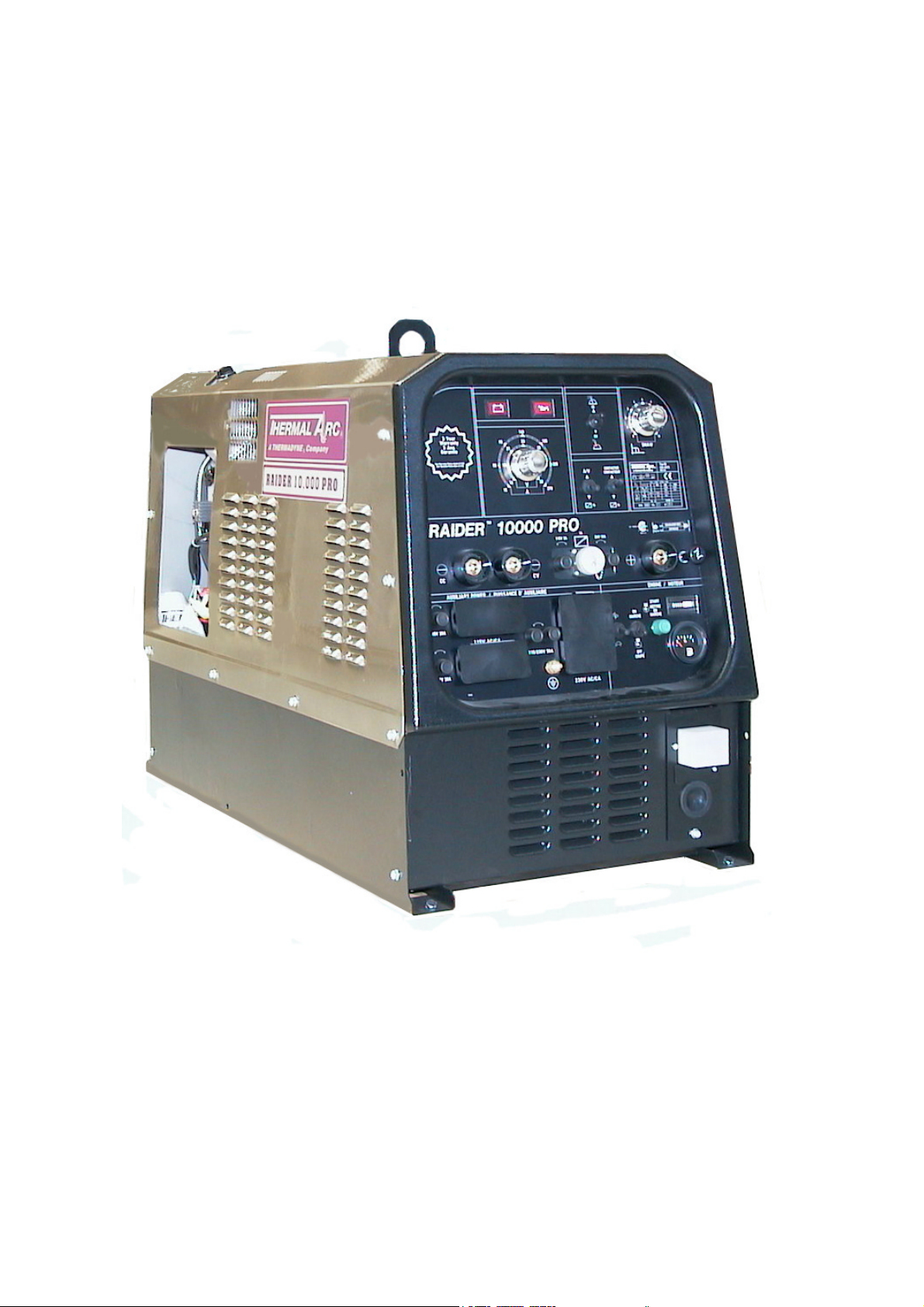
Raider 10,000 Pro
DC CC/CV Welding Generator
STICK
MIG
AUXILIARY POWER
Owners Manual
Date 06/01/04 KLA
MI335-06-00-05
1
Manual 430429-501
Page 2
Date 06/01/04 KLA
2
Manual 430429-501
Page 3

Table of Contents
Statement of Warranty .................................................................................................................................................................5
SECTION 1: GENERAL INFORMATION ................................................................................................................................6
1.01 Notes, Cautions and Warnings........................................................................................................................................6
1.02 Important Safety Precautions..........................................................................................................................................6
1.03 Publications.....................................................................................................................................................................7
1.04 Note, Attention et Avertissement....................................................................................................................................8
1.05 Precautions De Securite Importantes ..............................................................................................................................8
1.06 Documents De Reference..............................................................................................................................................10
SECTION 2: TECHNICAL SPECIFICATIONS....................................................................................................................13
2.01 Specifications.................................................................................................................................................................13
2.02 Volt-Amp Curve ............................................................................................................................................................14
2.03 Duty Cycle .....................................................................................................................................................................14
2.04 Front Panel Descriptions................................................................................................................................................14
2.05 Dimensions and Weight.................................................................................................................................................15
2.06 Maximum Welding Generator Operating Angles ..........................................................................................................15
2.07 Installing Welding Generator.........................................................................................................................................16
2.08 Location .........................................................................................................................................................................16
2.09 Air Flow Clearance........................................................................................................................................................16
2.10 Generator Auxiliary Power System................................................................................................................................17
2.11 Wiring Optional 230 Volt Plug ......................................................................................................................................18
2.12 Grounding The Generator ..............................................................................................................................................18
2.13 When Connecting To Home, Shop, or Farm Wiring......................................................................................................19
2.14 Auxiliary Power Requirements......................................................................................................................................19
2.15 Simultaneous Welding and Power .................................................................................................................................21
2.16 Selecting and Preparing Weld Output Cables................................................................................................................21
SECTION 3: TROUBLE SHOOTING GUIDE.........................................................................................................................23
3.01 There is No Auxiliary Voltage and/or Welding Current................................................................................................24
3.02 The Generator Is De-Energized when Load is connected ..............................................................................................24
3.03 Excessive Fall of Voltage When The Load is Connected ..............................................................................................25
3.04 Single Phase Receptacle Out Of Balance While at Idling..............................................................................................25
3.05 Insufficient Welding Current .........................................................................................................................................25
3.06 The Battery Runs down Frequently................................................................................................................................25
Section 5 Parts List ....................................................................................................................................................................26
5.01 Stator Parts.....................................................................................................................................................................26
5.02 Front Panel Parts............................................................................................................................................................28
5.03 Sheet Metal Parts ...........................................................................................................................................................30
5.04 Engine Related Parts......................................................................................................................................................32
5.05 Common Engine Part Numbers......................................................................................................................................34
5.06 Schematic.......................................................................................................................................................................35
5.07 14 pin Receptacle Signals ..............................................................................................................................................36
Date 06/01/04 KLA
3
Manual 430429-501
Page 4

Proposition 65
WARNING: This product, when used for welding or cutting,
produces fumes or gases which contain chemicals known to the
State of California to cause birth defects and, in some cases,
cancer. (California Health & Safety Code Sec.25249.5 et seq.)
Date 06/01/04 KLA
4
Manual 430429-501
Page 5

Statement of Warranty
LIMITED WARRANTY: Thermal Arc®, Inc., A Thermadyne Company, hereafter, “Thermal Arc” warrants to customers of its
authorized distributors hereafter “Thermal; Arc” that its products will be free of defects in workmanship or material. Should any failure to
conform to this warranty appear within the time period applicable to the Thermal Arc products as stated below, Thermal Arc shall, upon
notification thereof and substantiation that the product has been stored, installed, operated, and maintained in accordance with Thermal
Arc’s specifications, instructions, recommendations and recognized standard industry practice, and not subject to misuse, repair, neglect,
alteration, or accident, correct such defects by suitable repair or replacement, at Thermal Arc’s sole option, of any components or parts of
the product determined by Thermal Arc to be defective.
THERMAL ARC MAKES NO OTHER WARRANTY, EXPRESS OR IMPLIED. THIS WARRANTY IS EXCLUSIVE AND IN
LIEU OF ALL OTHERS, INCLUDING, BUT NOT LIMITED TO ANY WARRANTY OF MERCHANTABILITY OR FITNESS
FOR ANY PARTICULAR PURPOSE.
LIMITATION OF LIABILITY: Thermal Arc shall not under any circumstances be liable for special, indirect or consequential damages,
such as, but not limited to, lost profits and business interruption. The remedies of the Purchaser set forth herein are exclusive and the
liability of Thermal Arc with respect to any contract, or anything done in connection therewith such as the performance or breach thereof,
or from the manufacture, sale, delivery, resale, or use of any goods covered by or furnished by Thermal Arc whether arising out of contract,
negligence, strict tort, or under any warranty, or otherwise, shall not, except as expressly provided herein, exceed the price of the goods
upon which such liability is based. No employee, agent, or representative of Thermal Arc is authorized to change this warranty in any way
or grant any other warranty.
PURCHASER'S RIGHTS UNDER THIS WARRANTY ARE VOID IF REPLACEMENT PARTS OR ACCESSORIES ARE
USED WHICH IN THERMAL ARC’S SOLE JUDGEMENT MAY IMPAIR THE SAFETY OR PERFORMANCE OF ANY
THERMAL ARC PRODUCT.
PURCHASER'S RIGHTS UNDER THIS WARRANTY ARE VOID IF THE PRODUCT IS SOLD TO PURCHASER BY NONAUTHORIZED PERSONS.
The warranty is effective for the time stated below beginning on the date that the authorized distributor delivers the products to the
Purchaser. Notwithstanding the foregoing, in no event shall the warranty period extend more than the time stated plus one year from the
date Thermal Arc delivered the product to the authorized distributor.
POWER SUPPLIES POWER SUPPLIES & WIRE FEEDERS LABOR
MAIN POWER MAGNETICS (STATIC & ROTATING) 3 YEAR 3 YEAR
ORIGINAL MAIN POWER RECTIFIER 3 YEAR 3 YEAR
POWER SWITCHING SEMI-CONDUCTORS & CONTROL PC BOARD 3 YEAR 3 YEAR
ALL OTHER CIRCUITS AND COMPONENTS INCLUDING 1 YEAR 1 YEAR
BUT NOT LIMITED TO, CONTACTORS, RELAYS,
SOLENOIDS, PUMPS, SWITCHES, MOTORS
ENGINES: ENIGINES ARE NOT WARRANTED BY THERMAL ARC, ALTHOUGH MOST ARE WARRANTED BY THE
ENGINE MANUFACTURER, SEE THE ENGINE MANUFACTURES WARRANTY FOR DETAILS.
CONSOLES, CONTROL EQUIPMENT, HEAT 1 YEAR 1 YEAR
EXCHANGES, AND ACCESSORY EQUIPMENT
PLASMA TORCH AND LEADS, AND REMOTE CONTROLS 180 DAYS 180 DAYS
REPAIR/REPLACEMENT PARTS 90 DAYS 90 DAYS
NOTE: Dragster
Warranty repairs or replacement claims under this limited warranty must be submitted to Thermal Arc by an authorized Thermal Arc repair
facility within thirty (30) days of purchaser’s notice of any Warranty Claim. No transportation costs of any kind will be paid under this
warranty. Transportation charges to send products to an authorized warranty repair facility shall be the responsibility of the Purchaser. All
returned goods shall be at the Purchaser’s risk and expense. This warranty supersedes all previous Thermal Arc warranties.
Thermal Arc® is a Registered Trademark of Thermadyne Industries Inc.
TM
80 excluded from this policy. Refer to Dragster
TM
80 warranty in Dragster
TM
80 Owner’s Manual.
Effective April 1, 2002
Date 06/01/04 KLA
5
Manual 430429-501
Page 6

SECTION 1: GENERAL
INFORMATION
1.01 Notes, Cautions and
Warnings
Throughout this manual, notes, cautions, and warnings are
used to highlight important information. These highlights
are categorized as follows:
NOTE
An operation, procedure, or background
information which requires additional emphasis
or is helpful in efficient operation of the system.
CAUTION
A procedure which, if not properly followed, may
cause damage to the equipment.
WARNING
A procedure which, if not properly followed, may
cause injury to the operator or others in the
operating area.
1.02 Important Safety
• Use an air-supplied respirator if ventilation is not
adequate to remove all fumes and gases.
• The kinds of fumes and gases from the arc
welding/cutting depend on the kind of metal being
used, coatings on the metal, and the different
processes. You must be very careful when cutting or
welding any metals which may contain one or more
of the following:
Antimony Chromium Mercury
Arsenic Cobalt Nickel
Barium Copper Selenium
Beryllium Lead Silver
Cadmium Manganese Vanadium
• Always read the Material Safety Data Sheets (MSDS)
that should be supplied with the material you are
using. These MSDSs will give you the information
regarding the kind and amount of fumes and gases
that may be dangerous to your health.
• For information on how to test for fumes and gases in
your workplace, refer to item 1 in Subsection 1.03,
Publications in this manual.
• Use special equipment, such as water or down draft
welding/cutting tables, to capture fumes and gases.
• Do not use the welding torch in an area where
combustible or explosive gases or materials are
located.
• Phosgene, a toxic gas, is generated from the vapors of
chlorinated solvents and cleansers. Remove all
sources of these vapors.
Precautions
WARNING
OPERATION AND MAINTENANCE OF ARC
WELDING EQUIPMENT CAN BE
DANGEROUS AND HAZARDOUS TO YOUR
HEALTH.
To prevent possible injury, read, understand and
follow all warnings, safety precautions and
instructions before using the equipment. Call 1603-298-5711 or your local distributor if you
have any questions.
GASES AND FUMES
Gases and fumes produced during the Arc welding/cutting
process can be dangerous and hazardous to your health.
• Keep all fumes and gases from the breathing area.
Keep your head out of the welding fume plume.
ELECTRIC SHOCK
Electric Shock can injure or kill. The arc welding process
uses and produces high voltage electrical energy. This
electric energy can cause severe or fatal shock to the
operator or others in the workplace.
• Never touch any parts that are electrically “live” or
“hot.”
• Wear dry gloves and clothing. Insulate yourself from
the work piece or other parts of the welding circuit.
• Repair or replace all worn or damaged parts.
• Extra care must be taken when the workplace is moist
or damp.
GENERAL INFORMATION
6
Page 7

• Install and maintain equipment according to NEC
code, refer to item 4 in Subsection 1.03,
Publications.
• Disconnect power source before performing any
service or repairs.
• Read and follow all the instructions in the Operating
Manual.
FIRE AND EXPLOSION
Fire and explosion can be caused by hot slag, sparks, or
the arc weld.
• Be sure there is no combustible or flammable
material in the workplace. Any material that cannot
be removed must be protected.
• Ventilate all flammable or explosive vapors from the
workplace.
• Do not cut or weld on containers that may have held
combustibles.
• Provide a fire watch when working in an area where
fire hazards may exist.
• Hydrogen gas may be formed and trapped under
aluminum workpieces when they are cut underwater
or while using a water table. DO NOT cut
aluminum alloys underwater or on a water table
unless the hydrogen gas can be eliminated or
dissipated. Trapped hydrogen gas that is ignited
will cause an explosion.
NOISE
Noise can cause permanent hearing loss. Arc
welding/cutting processes can cause noise levels to
exceed safe limits. You must protect your ears from loud
noise to prevent permanent loss of hearing.
• To protect your hearing from loud noise, wear
protective ear plugs and/or ear muffs. Protect others
in the workplace.
• Noise levels should be measured to be sure the
decibels (sound) do not exceed safe levels.
• For information on how to test for noise, see item 1 in
Subsection 1.03, Publications, in this manual.
ARC WELDING RAYS
Arc Welding/Cutting Rays can injure your eyes and burn
your skin. The arc welding/cutting process produces very
bright ultra violet and infra red light. These arc rays will
damage your eyes and burn your skin if you are not
properly protected.
• To protect your eyes, always wear a welding helmet
or shield. Also always wear safety glasses with side
shields, goggles or other protective eye wear.
• Wear welding gloves and suitable clothing to protect
your skin from the arc rays and sparks.
• Keep helmet and safety glasses in good condition.
Replace lenses when cracked, chipped or dirty.
• Protect others in the work area from the arc rays. Use
protective booths, screens or shields.
• Use the shade of lens as recommended in Subsection
1.03, item 4.
1.03 Publications
Refer to the following standards or their latest revisions
for more information:
1. OSHA, SAFETY AND HEALTH STANDARDS,
29CFR 1910, obtainable from the Superintendent of
Documents, U.S. Government Printing Office,
Washington, D.C. 20402
2. ANSI Standard Z49.1, SAFETY IN WELDING AND
CUTTING, obtainable from the American Welding
Society, 550 N.W. LeJeune Rd, Miami, FL 33126
3. NIOSH, SAFETY AND HEALTH IN ARC
WELDING AND GAS WELDING AND CUTTING,
obtainable from the Superintendent of Documents,
U.S. Government Printing Office, Washington, D.C.
20402
4. ANSI Standard Z87.1, SAFE PRACTICES FOR
OCCUPATION AND EDUCATIONAL EYE AND
FACE PROTECTION, obtainable from American
National Standards Institute, 1430 Broadway, New
York, NY 10018
5. ANSI Standard Z41.1, STANDARD FOR MEN’S
SAFETY-TOE FOOTWEAR, obtainable from the
American National Standards Institute, 1430
Broadway, New York, NY 10018
6. ANSI Standard Z49.2, FIRE PREVENTION IN THE
USE OF CUTTING AND WELDING PROCESSES,
obtainable from American National Standards
Institute, 1430 Broadway, New York, NY 10018
7. AWS Standard A6.0, WELDING AND CUTTING
CONTAINERS WHICH HAVE HELD
COMBUSTIBLES, obtainable from American
Welding Society, 550 N.W. LeJeune Rd, Miami, FL
33126
8. NFPA Standard 51, OXYGEN-FUEL GAS SYSTEMS
FOR WELDING, CUTTING AND ALLIED
PROCESSES, obtainable from the National Fire
Protection Association, Batterymarch Park, Quincy,
GENERAL INFORMATION
MA 02269
7
Page 8

9. NFPA Standard 70, NATIONAL ELECTRICAL
CODE, obtainable from the National Fire Protection
Association, Batterymarch Park, Quincy, MA 02269
10. NFPA Standard 51B, CUTTING AND WELDING
PROCESSES, obtainable from the National Fire
Protection Association, Batterymarch Park, Quincy,
MA 02269
11.CGA Pamphlet P-1, SAFE HANDLING OF
COMPRESSED GASES IN CYLINDERS, obtainable
from the Compressed Gas Association, 1235 Jefferson
Davis Highway, Suite 501, Arlington, VA 22202
12. CSA Standard W117.2, CODE FOR SAFETY IN
WELDING AND CUTTING, obtainable from the
Canadian Standards Association, Standards Sales, 178
Rexdale Boulevard, Rexdale, Ontario, Canada M9W
1R3
13. NWSA booklet, WELDING SAFETY
BIBLIOGRAPHY obtainable from the National
Welding Supply Association, 1900 Arch Street,
Philadelphia, PA 19103
14. American Welding Society Standard AWSF4.1,
RECOMMENDED SAFE PRACTICES FOR THE
PREPARATION FOR WELDING AND CUTTING
OF CONTAINERS AND PIPING THAT HAVE
HELD HAZARDOUS SUBSTANCES, obtainable
from the American Welding Society, 550 N.W.
LeJeune Rd, Miami, FL 33126
15 ANSI Standard Z88.2, PRACTICE FOR
RESPIRATORY PROTECTION, obtainable from
American National Standards Institute, 1430
Broadway, New York, NY 10018
AVERTISSEMENT
Toute procédure pouvant provoquer des
blessures de l’opérateur ou des autres personnes
se trouvant dans la zone de travail en cas de
non-respect de la procédure en question.
1.05 Precautions De
Securite Importantes
AVERTISSEMENT
L’OPÉRATION ET LA MAINTENANCE DU
MATÉRIEL DE SOUDAGE À L’ARC AU JET
DE PLASMA PEUVENT PRÉSENTER DES
RISQUES ET DES DANGERS DE SANTÉ.
Il faut communiquer aux opérateurs et au
personnel TOUS les dangers possibles. Afin
d’éviter les blessures possibles, lisez, comprenez
et suivez tous les avertissements, toutes les
précautions de sécurité et toutes les consignes
avant d’utiliser le matériel. Composez le + 603298-5711 ou votre distributeur local si vous avez
des questions.
1.04 Note, Attention et
Avertissement
Dans ce manuel, les mots “note,” “attention,” et
“avertissement” sont utilisés pour mettre en relief des
informations à caractère important. Ces mises en relief
sont classifiées comme suit :
NOTE
Toute opération, procédure ou renseignement
général sur lequel il importe d’insister
davantage ou qui contribue à l’efficacité de
fonctionnement du système.
ATTENTION
Toute procédure pouvant résulter
l’endommagement du matériel en cas de nonrespect de la procédure en question.
FUMÉE et GAZ
La fumée et les gaz produits par le procédé de jet de
plasma peuvent présenter des risques et des dangers de
santé.
• Eloignez toute fumée et gaz de votre zone de
GENERAL INFORMATION
respiration. Gardez votre tête hors de la plume de
fumée provenant du chalumeau.
• Utilisez un appareil respiratoire à alimentation en air
si l’aération fournie ne permet pas d’éliminer la
fumée et les gaz.
• Les sortes de gaz et de fumée provenant de l’arc de
plasma dépendent du genre de métal utilisé, des
revêtements se trouvant sur le métal et des
différents procédés. Vous devez prendre soin
lorsque vous coupez ou soudez tout métal pouvant
contenir un ou plusieurs des éléments suivants:
antimoine cadmium mercure
argent chrome nickel
arsenic cobalt plomb
8
Page 9

baryum cuivre sélénium
béryllium manganèse vanadium
• Lisez toujours les fiches de données sur la sécurité
des matières (sigle américain “MSDS”); celles-ci
devraient être fournies avec le matériel que vous
utilisez. Les MSDS contiennent des renseignements
quant à la quantité et la nature de la fumée et des
gaz pouvant poser des dangers de santé.
• Pour des informations sur la manière de tester la
fumée et les gaz de votre lieu de travail, consultez
l’article 1 et les documents cités à la page 5.
• Utilisez un équipement spécial tel que des tables de
coupe à débit d’eau ou à courant descendant pour
capter la fumée et les gaz.
• N’utilisez pas le chalumeau au jet de plasma dans une
zone où se trouvent des matières ou des gaz
combustibles ou explosifs.
• Le phosgène, un gaz toxique, est généré par la fumée
provenant des solvants et des produits de nettoyage
chlorés. Eliminez toute source de telle fumée.
CHOC ELECTRIQUE
Les chocs électriques peuvent blesser ou même tuer. Le
procédé au jet de plasma requiert et produit de l’énergie
électrique haute tension. Cette énergie électrique peut
produire des chocs graves, voire mortels, pour l’opérateur
et les autres personnes sur le lieu de travail.
• Ne touchez jamais une pièce “sous tension” ou
“vive”; portez des gants et des vêtements secs.
Isolez-vous de la pièce de travail ou des autres
parties du circuit de soudage.
• Réparez ou remplacez toute pièce usée ou
endommagée.
• Prenez des soins particuliers lorsque la zone de
travail est humide ou moite.
• Montez et maintenez le matériel conformément au
Code électrique national des Etats-Unis. (Voir la
page 5, article 9.)
• Débranchez l’alimentation électrique avant tout
travail d’entretien ou de réparation.
• Lisez et respectez toutes les consignes du Manuel de
consignes.
INCENDIE ET EXPLOSION
Les incendies et les explosions peuvent résulter des
scories chaudes, des étincelles ou de l’arc de plasma. Le
procédé à l’arc de plasma produit du métal, des étincelles,
des scories chaudes pouvant mettre le feu aux matières
combustibles ou provoquer l’explosion de fumées
inflammables.
• Soyez certain qu’aucune matière combustible ou
inflammable ne se trouve sur le lieu de travail.
Protégez toute telle matière qu’il est impossible de
retirer de la zone de travail.
• Procurez une bonne aération de toutes les fumées
inflammables ou explosives.
• Ne coupez pas et ne soudez pas les conteneurs ayant
pu renfermer des matières combustibles.
• Prévoyez une veille d’incendie lors de tout travail
dans une zone présentant des dangers d’incendie.
• Le gas hydrogène peut se former ou s’accumuler
sous les pièces de travail en aluminium lorsqu’elles
sont coupées sous l’eau ou sur une table d’eau. NE
PAS couper les alliages en aluminium sous l’eau ou
sur une table d’eau à moins que le gas hydrogène
peut s’échapper ou se dissiper. Le gas hydrogène
accumulé explosera si enflammé.
RAYONS D’ARC DE PLASMA
Les rayons provenant de l’arc de plasma peuvent blesser
vos yeux et brûler votre peau. Le procédé à l’arc de
plasma produit une lumière infra-rouge et des rayons
ultra-violets très forts. Ces rayons d’arc nuiront à vos
yeux et brûleront votre peau si vous ne vous protégez pas
correctement.
• Pour protéger vos yeux, portez toujours un casque ou
un écran de soudeur. Portez toujours des lunettes de
sécurité munies de parois latérales ou des lunettes
de protection ou une autre sorte de protection
oculaire.
• Portez des gants de soudeur et un vêtement protecteur
approprié pour protéger votre peau contre les
étincelles et les rayons de l’arc.
GENERAL INFORMATION
• Maintenez votre casque et vos lunettes de protection
en bon état. Remplacez toute lentille sale ou
comportant fissure ou rognure.
• Protégez les autres personnes se trouvant sur la zone
de travail contre les rayons de l’arc en fournissant
des cabines ou des écrans de protection.
• Respectez le teint de lentille recommandé dans le
article 4, page 5.
• Hydrogen gas may be present under aluminum
workpieces during the cutting process when being
cut underwater or using a water table. DO NOT cut
aluminum underwater or on a water table unless the
hydrogen gas can be eliminated as the hydrogen gas
may detonate.
BRUIT
9
Page 10

Le bruit peut provoquer une perte permanente de l’ouïe.
Les procédés de soudage à l’arc de plasma peuvent
provoquer des niveaux sonores supérieurs aux limites
normalement acceptables. Vous dú4ez vous protéger les
oreilles contre les bruits forts afin d’éviter une perte
permanente de l’ouïe.
• Pour protéger votre ouïe contre les bruits forts, portez
des tampons protecteurs et/ou des protections
auriculaires. Protégez également les autres
personnes se trouvant sur le lieu de travail.
• Il faut mesurer les niveaux sonores afin d’assurer que
les décibels (le bruit) ne dépassent pas les niveaux
sûrs.
• Pour des renseignements sur la manière de tester le
bruit, consultez l’article 1, page 5.
1.06 Documents De
Reference
Consultez les normes suivantes ou les révisions les plus
récentes ayant été faites à celles-ci pour de plus amples
renseignements :
1. OSHA, NORMES DE SÉCURITÉ DU TRAVAIL
ET DE PROTECTION DE LA SANTÉ, 29CFR
1910, disponible auprès du Superintendent of
Documents, U.S. Government Printing Office,
Washington, D.C. 20402
2. Norme ANSI Z49.1, LA SÉCURITÉ DES
OPÉRATIONS DE COUPE ET DE SOUDAGE,
disponible auprès de la Société Américaine de
Soudage (American Welding Society), 550 N.W.
LeJeune Rd., Miami, FL 33126
3. NIOSH, LA SÉCURITÉ ET LA SANTÉ LORS
DES OPÉRATIONS DE COUPE ET DE
SOUDAGE À L’ARC ET AU GAZ, disponible
auprès du Superintendent of Documents, U.S.
Government Printing Office, Washington, D.C.
20402
4. Norme ANSI Z87.1, PRATIQUES SURES POUR
LA PROTECTION DES YEUX ET DU VISAGE
AU TRAVAIL ET DANS LES ECOLES, disponible
de l’Institut Américain des Normes Nationales
(American National Standards Institute), 1430
Broadway, New York, NY 10018
5. Norme ANSI Z41.1, NORMES POUR LES
CHAUSSURES PROTECTRICES, disponible
auprès de l’American National Standards Institute,
1430 Broadway, New York, NY 10018
6. Norme ANSI Z49.2, PRÉVENTION DES
INCENDIES LORS DE L’EMPLOI DE
PROCÉDÉS DE COUPE ET DE SOUDAGE,
disponible auprès de l’American National Standards
Institute, 1430 Broadway, New York, NY 10018
7. Norme A6.0 de l’Association Américaine du
Soudage (AWS), LE SOUDAGE ET LA COUPE
DE CONTENEURS AYANT RENFERMÉ DES
PRODUITS COMBUSTIBLES, disponible auprès
de la American Welding Society, 550 N.W. LeJeune
Rd., Miami, FL 33126
8. Norme 51 de l’Association Américaine pour la
Protection contre les Incendies (NFPA), LES
SYSTEMES À GAZ AVEC ALIMENTATION EN
OXYGENE POUR LE SOUDAGE, LA COUPE
ET LES PROCÉDÉS ASSOCIÉS, disponible
auprès de la National Fire Protection Association,
Batterymarch Park, Quincy, MA 02269
9. Norme 70 de la NFPA, CODE ELECTRIQUE
NATIONAL, disponible auprès de la National Fire
Protection Association, Batterymarch Park, Quincy,
MA 02269
10. Norme 51B de la NFPA, LES PROCÉDÉS DE
COUPE ET DE SOUDAGE, disponible auprès de
la National Fire Protection Association,
Batterymarch Park, Quincy, MA 02269
11. Brochure GCA P-1, LA MANIPULATION SANS
RISQUE DES GAZ COMPRIMÉS EN
CYLINDRES, disponible auprès de l’Association
des Gaz Comprimés (Compressed Gas
Association), 1235 Jefferson Davis Highway, Suite
501, Arlington, VA 22202
12. Norme CSA W117.2, CODE DE SÉCURITÉ
GENERAL INFORMATION
POUR LE SOUDAGE ET LA COUPE, disponible
auprès de l’Association des Normes Canadiennes,
Standards Sales, 178 Rexdale Boulevard, Rexdale,
Ontario, Canada, M9W 1R3
13. ivret NWSA, BIBLIOGRAPHIE SUR LA
SÉCURITÉ DU SOUDAGE, disponible auprès de
l’Association Nationale de Fournitures de Soudage
(National Welding Supply Association), 1900 Arch
Street, Philadelphia, PA 19103
14. Norme AWSF4.1 de l’Association Américaine de
Soudage, RECOMMANDATIONS DE
PRATIQUES SURES POUR LA PRÉPARATION
À LA COUPE ET AU SOUDAGE DE
CONTENEURS ET TUYAUX AYANT
RENFERMÉ DES PRODUITS DANGEREUX ,
disponible auprès de la American Welding Society,
550 N.W. LeJeune Rd., Miami, FL 33126
15. Norme ANSI Z88.2, PRATIQUES DE
PROTECTION RESPIRATOIRE, disponible auprès
de l’American National Standards Institute, 1430
Broadway, New York, NY 10018
10
GENERAL INFORMATION
Page 11

SECTION 2: TECHNICAL SPECIFICATIONS
2.01 Specifications
The Thermal Arc Raider 10,000 Pro is a gasoline engine driven DC welding generator with selectable Constant Current (CC)
and Constant Voltage (CV) output characteristics. This unit is designed for use with Shielded Metal Arc Welding (SMAW),
Gas Metal Arc Welding (GMAW), and GAS Tungsten Arc Welding - (GTAW) processes.
Specifications
DC
Amperage Range 15 – 270
Duty Cycle 270 @ 60%
AC/DC welding current 250 @ 100%
Volt Range CV Mode 16 – 30
OCV CC Mode 70 VDC
Auxiliary Power
Single Phase 115 2ea GFCI Duplex Receptacles 3.5Kva
Single Phase 115/240 8.5Kva
Three Phase 460 10Kva
Engine
Make/Type HONDA
Model series GX 620K1
Number of cylinders 2
Displacement 614 cc.
Power 20 HP
Engine Speed 3750 rpm no load
Engine speed 2600 rpm Idle
Cooling system Air
Oil capacity 1.5 l. - 0,42 gl.
Fuel capacity 37.5 l. - 10 gl.
Fuel consumption 5.2 l/h – 1.4 gl./Hr
Battery 12V 340A
13
TECHNICAL SPECIFICATIONS
Page 12

2.02 Volt-Amp Curve
NOTE
Volt-ampere curves show the voltage and amperage
output capabilities of the welding power source. Curves of
other settings will fall between the curves shown.
2.03 Duty Cycle
The duty cycle of a welding generator is the percentage of
a ten-minute period that a welding generator can be
operated at a given output without causing overheating
and damage of the unit. This unit is rated at 60 percent
duty cycle when operated at 270 amperes. The unit can be
operated at 270 amperes for six consecutive minutes, but
it must operate at no load for the remaining four minutes
to allow proper cooling. If the welding amperes decrease,
the duty cycle increases. If the welding amperes are
increased beyond rated output, the duty cycle will
decrease.
CAUTION: CONTINUAL OPERATION
EXCEEDING THE DUTY CYCLE RATINGS CAN
CAUSE DAMAGE TO THE WELDING POWER
SOURCE.
2.04 Front Panel
Descriptions
5
4
6
CC
3
7
2
8
9
1
CV
0
10
SMAW
CONTACTOR
A/V
CONTACTEUR
+-
14
14
14
24V 10A
ENGINE
/ MOTEUR
START
METTRE
ON
EN
MARCHE
MARCHE
OFF
COUPE
55
TM
/ PUISSANCE D' AUXILIAIRE
115V A C/CA
140
95
23 185
21
25
28
225
18
30
16
8
15
270
)
115V 3A
115/230V 50A
230V AC/CA
3 Year
Warranty
3 Ans
Garantie
See Warranty Policy dated 4/1/02
Voir Garantie Police date 4/1/02
RAIDER 10000 PRO
++ +8
AUXILIARY POWER
115V 20A
115V 20A
Front Panel
1. 230/115V Single Phase Receptacle - Supplies 60 Hz
single-phase power at weld/power speed.
2. Earth connection – used to earth ground the generator
for auxiliary power.
3. 230/115V 50A Circuit breakers - Push to reset.
Controls 230/115V power source for the 230/115V
receptacle.
4. 115V 20A Circuit Breakers - Push to reset. Controls
115V power source for the 115V duplex GFCI
receptacles.
5. 115 V Single Phase GFCI Receptacle – Supplies 60
Hz single-phase power at weld/power speed
6. Welding Receptacle Work: Negative output welding
connection for CC (Constant current) STICK.
7. Welding receptacle Work : Negative output welding
connection for CV (Constant voltage) MIG.
8. 115V 3A Circuit breaker – Push to reset. Controls
115V power source for wire feeders Controlled
through the 14 pin receptacle.
9. Oil Level Lamp - When the ON/OFF Switch is
turned on the Oil Level Lamp will Not Glow. Should
the oil sensor in the engine detect a low oil condition
the Oil Level Lamp will turn-on and the engine will
shut off.
10. Amperage /Voltage control – detects the desired
Amperage or voltage (depending on mode) within the
entire range of the welding generator. The scale
surrounding the control represents approximate actual
values.
14
GENERAL INFORMATION
Page 13

11. Battery Charge Lamp – When the ON/OFF Switch is
turned on the Battery Charge Lamp will Glow. For
normal operation when the engine is running the
Battery Carge Lamp will be off. Should the Charging
circuit or Battery fail the Battery Warning Lamp will
Turn-on and the engine will shut off.
12. Remote AMPERAGE / VOLTAGE Switch – Allows
remote amperage/voltage device operation through
the 14 pin receptacle.
13. Process Selector switch : CC/CV – Allows the
operator to select the CC (Constant Current) process
or CV (Constant voltage) process.
14. Remote Contactor switch – Allows for the output
contactor to be controlled through the 14 pin
receptacle. When in the Panel position welding
output is present at the output terminal when the
engine is running. When in Remote position output is
controlled through a 14 pin remote device.
15. Arc Control – The Arc Control is use in the SMAW
mode only. Rotate the control clockwise to increase
the short circuit current available to control the
welding arc.
16. 14 Pin receptacle - Used for remote Contactor,
amperage control, and wire feeder control.
17. Serial number.
18. Welding Receptacle: Electrode-Positive output
welding connection for CC (Constant Current) and
CV (Constant Voltage).
19. Choke – Pull knob out engges Choke. Push knob in
for normal operation.
20. 24V AC 10A Circuit breaker – Push to reset.
Controls 24V power source for wire feeders.
Controlled through the 14 pin receptacle.
21. Hour meter - Monitors Time in hours when the
engine is on.
22. Fuel Gauge – Monitors fuel level
23. START button – Used to start the engine. Set the
ON/OFF switch to ON, push START button to the
start the engine. When engine starts release button
24. Engine ON/OFF switch - Place in the ON position to
operate generator. Use the START button to start the
engine. To shut off engine place switch in stop
position.
25. Engine Min/Max R.P.M. switch
26. 13A Circuit breaker - 3 poles circuit breaker controls
460V three phase power source.
27. 460V Output - Access for three phase 460V 60 Hz
connections. Connect Line1, 2 and 3 to the output
side of the circuit breaker and the ground to the bolt
mounted beside the circuit breaker.
2.05 Dimensions and Weight
Height 710mm 27.9”
Width 530mm 20.86”
Length 1080mm 42.52”
A 15mm .59”
B 1050mm 41.34”
C 34.5mm 1.36”
D 424mm 16.69”
E 10.5mm Dia. .41” Dia.
Weight 248 Kg 546.5 lb
2.06 Maximum Welding
Generator Operating Angles
Do not exceed operating angles while running or engine
damage will occur.
The operating angle is a maximum of 25 degrees.
15
GENERAL INFORMATION
Page 14

2.07 Installing Welding
Generator
1. Lifting forks.
2. Lifting Eye. Use lifting eye or lifting forks to move
unit. If using lifting forks, extend forks beyond
opposite side of unit.
3. Trailer - Install unit on trailer according to trailer
manufacturing.
Movement - Do not lift unit from end.
1 2
2.09 Air Flow Clearance
Maintain at least 19.7 inch (500mm) of unrestricted space
on all sides of the unit, and keep underside free of
obstructions. Do not place any filtering device over the
intake air passages of this welding generator. Warranty is
void if any type of filtering device is used.
The service life and operating efficiency of this unit is
reduced when the unit is subjected to high levels of dust,
dirt, moisture, and corrosive vapors.
2.08 Location
A proper installation site should be selected for the welding
generator if the unit is to provide dependable service and
remain relatively maintenance free.
CAUTION: OPERATE IN OPEN, WELLVENTILATED AREAS, OR IF OPERATED
INDOORS, VENT ENGINE EXHAUST OUTSIDE THE
BUILDING. KEEP ENGINE EXHAUST OUTLET
AWAY FROM BUILDING EXTERIER, INTERIER
WALLS & AIR INTAKES.
WARNING: SPARKS CAN CAUSE BATTERY
GASES TO EXPLODE BATTERY ACID CAN
BURN EYES AND SKIN.
• Stop engine before disconnecting or connecting
battery cables.
• Always wear a faceshield and proper protective
clothing when working on battery.
• Do not allow tools to cause sparks when working on
a battery.
• Place the engine control switch in the STOP position.
• Remove bolts and pull out tray.
• Connect the cables
• Reinstall battery tray.
16
TECHNICAL SPECIFICATIONS
Page 15

WARNING: ENGINE FUEL CAN CAUSE FIRE OR
EXPLOSION.
• Stop engine before fueling.
• Do not fuel while smoking or near sparks or flames.
• Do not overfill tank-clean up any spilled fuel.
REMOVE FUEL CAP SLOWLY-FUEL SPRAY
MAY CAUSE INJURY. FUEL MY BE UNDER
PRESSURE. Rotate fuel cap slowly and wait until
hissing stops before removing cap. Engine must be
cold and on a level surface.
2.10 Generator Auxiliary
Power System
Standard Receptacles
(1) Circuit breakers to protect (2) GFCI receptacles from
overload.
(2) 120 V 15 A AC Duplex GFCI receptacle. Supplies 60
Hz single-phase power at maximum speed (3600 rpm).
Maximum output each receptacle is 1.8 kVA/kW.
(3) Circuit breakers to protect (4) 240 V receptacle from
overload.
460 Three Phase connection
(1) 460 V 13 A AC three phase Circuit Breaker
connection. Supplies 60 Hz three-phase power at
maximum speed (3600 rpm). Maximum output is 10
kVA/kW.
To connect load remove the two retaining knobs holding
the access panel. After opening the panel connect a cable
to be used to supply the 460V three phase load to the
three phase circuit breaker mounted to the access panel.
Connected the ground cable to the bolt mounted next to
the circuit breaker. Route the cable through the cable
clamp (2) and secure cable. Re-secure the access panel
with the two retaining knobs to the front panel.
(4) 240 V 50 A AC receptacle. Supplies 60 Hz singlephase power at maximum speed (3600 rpm). Maximum
output is 8.5 kVA/kW.
(5) Earth ground connection.
5
17
TECHNICAL SPECIFICATIONS
Page 16

2.11 Wiring Optional 230
2.12 Grounding The
Volt Plug
The plug can be wired for a 230V, 2-wire load or a
115/230V, 3-wire load. See diagram below
White - Neutral terminal.
YYY - Load 1 terminal.
XXX - Load 2 terminal.
Green - Ground terminal.
Generator
TO A TRUCK OR TRAILER FRAME
1. Generator base.
2. Metal vehicle frame.
3. Equipment grounding terminal.
4. Grounding cable. Use # 10 AGW or larger insulated
copper wire.
NOTE: FOR THE GFCI RECEPTACLES TO
PERFORM PROPER PROTECTION THE WELDING
GENERATOR MUST BE EARTH GROUNDED.
Select proper insolated and grounded equipment.
1) Auxiliary power receptacles are Neutral bonded to
frame.
2) 3-Prong plug for case Grounded equipment
3) 2-Prong plug for double insulated equipment.
18
TECHNICAL SPECIFICATIONS
Page 17

2.13 When Connecting To
Home, Shop, or Farm
Wiring
NOTE: THIS UNIT SHOULD NEVER BE USED AS
THE MAIN SOURCE OF POWER.
1. Equipment grounding terminal.
2. Grounding cable. Use # 10 AGW or larger insulated
copper wire.
3. Water meter.
4. Metal water pipe
5. Driven ground rod.
NOTE: It is the installer's responsibility to follow the
applicable rules from the National Electrical Code
(NEC), state, local, and OSHA codes for the
installation and use of auxiliary power generators.
Typical connection to supply emergency or standby power.
1. Power Company Service Meter.
2. Main and Branch Over-current Protection.
3. Double-Pole, Double-Throw Transfer Switch.
Obtain and install correct switch. Switch rating
be same as or greater than the branch over-current
protection.
4. Circuit Breaker or Fused Disconnect Switch. Obtain
and install correct switch.
5. Extension Cord. Generator Connections. Connect
terminals or plug of adequate amperage capacity to
cord. Follow all applicable codes and safety
practices. Turn off or unplug all equipment
connected to generator before starting or stopping
engine. When starting or stopping, the engine has
low speed which causes low voltage and frequency.
6. Load connections.
must
Customer-supplied equipment is required if generator is to
supply standby power during emergencies or power
outages.
2.14 Auxiliary Power
Requirements
The following section provides some general guidelines for
the installation and operation of an auxiliary power generator.
Not all the guidelines may be applicable to this specific unit.
The auxiliary power supplied from the generator is most
commonly used in industrial, small business and
residential applications. For industrial applications, a
portable unit can be moved to the job site to power
portable tools, lights, compressors, etc. For small
business and residential applications, the generator
supplies standby power during a power outage.
It is the installer’s responsibility to follow all applicable
codes when installing an auxiliary power generator. It is
also the installer’s responsibility to determine if the
generator is capable of supplying adequate power for a
specific application. When installing consult qualified
19
TECHNICAL SPECIFICATIONS
Page 18

local personnel and follow all applicable codes for safe
and proper installation.
Before the generator may be used to supply power, the
installer must first become familiar with and meet all
codes applicable to the installation of an auxiliary
generator. It is the installer's responsibility to follow the
applicable rules from the National Electrical Code (NEC),
state, local, and OSHA codes for the installation and use
of auxiliary power generators.
LOAD EVALUATION
Before connecting or operating the auxiliary power
generator, the installer must determine if the generator is
capable of supplying adequate power for a specific
application. Load and generator evaluation is essential for
satisfactory generator and equipment operation.
Motor-starting Requirements
Starting amperage requirements are many times the
running amperage of the motor. Starting requirements
must be determined to assure that the generator is capable
of starting the motor without damaging it. This can be
done by examining the motor nameplate and identifying
the code letter specifying the starting kVA/HP required.
Motor Start
Code Leter
G6.3
H7.1
J8.0
K9.0
L 10.0
M 11.2
N 12.5
P 14.0
KVA/HP
TYPES OF LOAD
Load requirements depend on the type of load connected
to the generator. There are two types of loads, resistive
and non-resistive. A resistive load, such as a light bulb,
requires a constant amount of power from the generator.
A non-resistive load, such as a portable grinder, requires
variable amounts of power from the generator. Because a
grinder requires more power for motor starting and is
rarely used with a constant, even pressure, the load
requirements can change greater than the operator
anticipates.
RUNNING LOAD REQUIREMENTS
The total running load applied to the generator is
calculated by adding up all the individual loads. Some
requirements are rated in amperes, others in watts. The
requirements for most equipment is provided on its
nameplate.
Example 1: If a drill requires 5 amperes at 115 volts,
calculate its running power requirements in watts.
VOLTS x AMPERES = WATTS
115V x 5A = 575W
Therefor, the individual load applied by the drill is 575
watts.
Example 2: If a light bulb is rated at 200 watts, the
individual load applied the light bulb is 200 watts. If
three 200 watt light bulbs are used with the drill from
example 1 add the individual loads to calculate total load.
(200W + 200W + 200W) + 575W = 1175W
If the kVA/HP requirement, motor horsepower, and
voltage rating are known, the starting amperage can be
calculated.
Example: Calculate the starting amperage required for a
230V, ¼ HP motor with a motor start code of G.
Equation
KVA/HP x HP x 1000
= STARTING AMPERAGE
VOLTS
Volts = 230
HP = ¼
Code G results in kVA/HP = 6.3
6.3 x ¼ x 1000
= 6.85A
230
Therefore, starting the motor requires 6.85 amperes.
If a code letter is not present on the motor nameplate,
approximate starting amperage is equal to six times
running amperage. This is a reasonable approximation for
all applications where the generator rated amperage is at
least twice the motor requirement. If the generator-tomotor-size ratio is less than 2:1 acquire the needed
information to properly determine the motor-starting
requirement.
Therefore the total load applied by the three light bulbs
and drill is 1175 watts.
20
TECHNICAL SPECIFICATIONS
Page 19

2.15 Simultaneous Welding
and Power
((ssiinnggllee oorr tthhrreeee pphhaassee)
Weld
Current
270A 1,200 10A 5A 1.5A
220A 3,660 15A x 2 15.25A 4.6A
170A 4,500 15A x 2 18.75A 5.65A
120A 7,000 15A x 2 29A 8.8A
70A 8,500 15A x 2 35.4A 10.68A
0A 10,000 15A x 2 35.4A 12.5A
CCoommbbiinneedd oouuttppuutt ooff aallll rreecceeppttaacclleess lliimmiitteedd ttoo rraattiinngg ooff tthhe
ggeenneerraattoorr.
Total
Power
in Watts
.
120 volt
GFCI
Recept.
)
240 volt
Recept.
8500 max.
460 volt
Three
phase
WELD CABLE CONNECTIONS
1. Do not touch live electrical parts.
2. Shut down unit before making any weld output
connections.
3. Do not change position of the welding cable
connectors while welding
4. Be sure that the connectors are secure in receptacle
before welding.
TYPICAL PROCESS CONNECTIONS
SEQUENCE OF OPERATION
e
WARNING: Read and follow all safety precaution
before proceeding with operation.
EExxaammppllee:: IIff wweellddiinngg aatt 112200AA aanndd 1155AA iiss ddrraawwnn ffrroomm tthhe
112200VV GGFFCCII dduupplleexx rreecceeppttaaccllee,, 1100AA iiss ddrraawwnn ffrroomm tthhe
224400VV rreecceeppttaaccllee,, oonnllyy 33..55AA iiss aavvaaiillaabbllee ooff 446600VV tthhrreeee-
.
pphhaassee.
e
-
2.16 Selecting and Preparing
Weld Output Cables
CONNECTOR INSTALLATION
Install the supplied male connectors onto proper cables.
1. Obtain cable of desired length and proper size for
installation.
2. If the installation requires cable large than 3/0 AWG,
prepare one end of 3/0 AWG pigtail no longer than 2
ft (0,61 m) for connector installation. The remaining
end of the pigtail is connected to the main run of 3/0
AWG or larger weld cable.
3. Push weld cable through insulator.
4. Remove 0.79 in (20 mm) of insulation from end of
cable.
5. Install supplied sleeve on stripped end of cable.
6. Insert cable with sleeve into connector body so that
cable is snug and against bottom of connector body.
7. Install and tighten set screw with supplied hex wrench
to secure connector body onto cable.
7. Push insulator onto connector body to cover set
screw.
e
SHIELDED METAL ARC WELDING (SMAW)
1. Install and connect unit according to the installation
section.
2. Wear gloves, Welding Helmet and protective clothing.
3. Connect work clamp at workplace.
4. Select proper electrode.
5. Place the selector switch in STICK position.
6. Place the OUTPUT CONTACTOR switch in ON
position.
7. If remote amperage control is not used, place the
Amperage/Voltage switch in panel position.
8. Rotate the Amperage/Voltage control to desired
position.
9. Insert electrode into electrode holder.
GAS TUNGSTEN ARC WELDING (GTAW) Lift Start only
1. Install and connect unit according to the Installation
section.
2. Select proper tungsten electrode.
3. Prepare tungsten electrode and connect the torch to
the negative output terminal.
4. Wear gloves, welding helmet and protective clothing.
5. Connect work clamp to positive output terminal and
work place.
6. Place the process selector switch in Lift Tig position.
7. For remote contactor and/or amperage control connect
a remote device to the 14 pin receptacle.
8. For remote amperage control place the
Amperage/Voltage switch in the panel position.
9. For remote contactor control place the contactor
switch in the panel position.
10. Rotate Amperage/Voltage control to desired position.
11. Turn on shielding gas and water supplies as
applicable.
12. Touch electrode to work and lift to start arc.
13. Begin welding.
21
TECHNICAL SPECIFICATIONS
Page 20

GAS METAL ARC WELDING (GMAW)
1. Install and connect unit according to the Installation
section.
2. Install and connect wire feed system according to
wire feeder installation guide.
3. Wear gloves, welding helmet and protective
clothing.
4. Connect work lead to the negative CV terminal.
5. Place the process selector switch in CV position.
6. If remote voltage control is not used, place the
Amperage/Voltage switch in panel position.
7. Rotate Amperage/Voltage control to desired position.
8. Turn on shielding gas supply and set desired flow
rate.
9. Begin welding.
SELECTING WELD CABLE SIZES
Weld cable size (AWG) is based on either a 4 volts or less
drop or a current density of more than 300 circular mils
per ampere.
100ft
(30 m)
Welding
Amperage
100 4 4 3 2
150 3 2 1 1/0
200 2 1 1/0 2/0
250 1 1/0 2/0 3/0
300 1/0 2/0 3/0 4/0
60-100%
Duty Cycle
150ft.
(45 m)
10-100% Duty Cycle
200ft.
(60 m)
250ft.
(70 m)
22
TECHNICAL SPECIFICATIONS
Page 21

SECTION 3: TROUBLE SHOOTING GUIDE
The Raider 10,000 Pro is an asynchronous (brush-less) style generator. The basic theory of this style generator is as follows:
A permanent magnet (rotor) is rotating at a high speed inside a winding wrapped around a laminated steel core (stator). This
produces a small voltage at a very low intensity, 1 to 2 volts at 1 amp in the exciter windings. This low voltage charges the
excitation capacitors connected in series and directly connected to both ends of the exciter windings. This produces a chargedischarge situation that augments to the point at which it stabilizes itself in proportion to the magnetic force of the rotor
winding wire’s size and length, capacity of the capacitors, and engine speed (3600 rpm) at about 60 times per second. The
Charge-discharge effect produces a collapsing of magnetic field in the laminated steel, thus creating a current all of its own.
This current produced is proportional to the main winding characteristics, size, length, et
Auxiliary
Output
Control
Bridge
Control PC
Board
23
TROUBLE SHOOTING
Page 22

3.01 There is No Auxiliary Voltage and/or Welding Current
In examining this particular fault it must be remembered that an asynchronous generator with excitation by capacitors
has the characteristic of becoming automatically de-energized while it is functioning (no longer supplies current). Also an
asynchronous generator will not self-excite when it is started up if there is a short-circuit whether outside of the generator
(in the user circuit) or inside it (in the windings and in the control equipment).
TROUBLE
POSSIBLE CAUSE
The GFCI is open or when
actuated in the closed position
suddenly trips open.
The generator is connected to the
maximum load, in particular
induction motors.
The + and - welding cables are in
short-circuit through electric
contact between them.
Excitation Capacitors are
shorted.
Output welding receptacles loose
or shorted.
Output Welding Rectifier is
shorted.
Faulty winding in stator. Have stator checked by
The reset of the G.F.C.I. must be
in the closed position. Check that
the user circuit does not have a
phase to earth.
When starting, the current plugs
should not be connected directly
with the load, but with a switch
interposed that will allow the set
to be started with the load
disconnected.
The electrode & Work lead are
connected in short circuit
condition.
Disconnect the capacitors from
the generator and from the
equipment. Refer to test section
for excitation capacitors.
Check the cable connections to
the receptacles. Check for burnt
or loose receptacle insulation.
Have Rectifier checked by
authorized service agent.
authorized service agent.
REMEDY
Close the GFCI and disconnect
the plugs from the current
sockets. If the GFCI does not
remain closed even if the reset is
slowly closed, this means that
the GFCI is faulty and that it
must be replaced.
Remove the load in the starting
phase. If necessary, disconnect
the plugs from the current
sockets. If generator still does
not generate welding current
refer to test section for exciter
capacitors & Stator.
Disconnect electrode & Work
leads. If generator still does not
generate welding current refer to
test section for exciter capacitors
& Stator.
If necessary, replace the
capacitors.
Replace the receptacle parts
necessary.
3.02 The Generator Is De-Energized when Load is connected
PROBABLE CAUSE CONTROLS REMEDIES
There is a short-circuit on the
user circuit.
Excessive overload; induction
motors (especially 2-pole)
connected of higher power than
the Generators specifications.
Check the load for shorts Repair load circuit.
See that the induction motors are
not of higher power than the
specification of the generator.
24
Reduce load to within the
specifications of the generator.
Page 23

3.03 Excessive Fall of Voltage When The Load is Connected
PROBABLE CAUSE CONTROLS REMEDIES
The engine does not maintain the
nominal speed.
Check whether the fine current
control is functioning.
Check engine fuel system. Refer to Engine manual for
Check with an ammeter whether
the load is greater than the rated
load of the generator.
Replace or repair Fine Current
control assembly.
testing fuel system.
Reduce load to within generator
specifications.
3.04 Single Phase Receptacle Out Of Balance While at Idling
PROBABLE CAUSE CONTROLS REMEDIES
A capacitor of one phase is
disconnected or is no longer
working properly.
Check the connections at the
terminals of the capacitors. See
capacitor testing in the the
Troubleshooting Guide.
Repair the faulty capacitor
connections. Replace any
capacitor that may be found to
be defective.
3.05 Insufficient Welding Current
PROBABLE CAUSE CONTROLS REMEDIES
The engine does not obtain
maximum speed.
One phase on the capacitors or
on the rectifiers is disconnected.
Check the Fine Current Control
function.
Check engine throttle linkage,
Fuel and electrical systems.
Check that all the internal
connections have a sound
electrical connection.
Repair or replace the Fine
Current Control.
Refer to engine manual.
Fix any connections that may
have worked loose.
3.06 The Battery Runs down Frequently
PROBABLE CAUSE CONTROLS REMEDIES
Battery defective: does not
maintain the load.
Engine charge circuit defective Test charge circuit according to
Check for shorted battery cell. Replace battery.
engine manual.
25
Page 24

Section 5 Parts List
5.01 Stator Parts
26
Page 25

Item Part Number Description
1 11-3284 Washer
2 11-3283 Fan
3 11-3077 Seeger ring
4 11-3078 Bearing
5 11-3633 Rotor tie-rod
6 11-3308 Flange with bearing seat
7 11-3954 Stator
8 11-3597 Hook
9 11-3281 Rotor
10 11-3307 Tie rod
11 11-3873 Engine bulkhead
12 11-3869 Silencer
13 11-3499 Flap
14 11-3721 Oil drain cap
15 11-3722 Hose clamp
16 11-3868 Clamp
17 11-3720 Oil drain pipe
18 11-3533 Washer
19 11-3851 Nut M8 mm
20 11-3017 Engine shock absorber 30x30 mm
21 11-3896 Screw M8x25 mm
22 11-3795 Engine holder
23 11-3871 Flange nut M5x16 mm
24 11-3659 Engine connection flange
25 11-3872 Washer M10 mm
26 11-3870 Screw M3/8’x1,¼ mm
27 11-3664 Stator plate
28 11-3660 Stator shock absorber 40x25 mm
27
Page 26

5.02 Front Panel Parts
28
Page 27

Item Part Number Description
1 11-3779 13A 3 poles circuit breaker
2 11-3143 3 poles circuit breaker cover
3 11-3138 Cable holder
4 11-3245 Circuit breaker support
5 11-3510 Protection cover
6 11-3087 Rubber wire holder
7 11-3936 Earth clamp
8 11-3810 O-ring
9 11-3150 Fuel gauge – Monitor fuel level
10 11-4133 230V 50A 14-50 single phase outlet
11 11-3789 230V 50A 14-50 single phase cover
12 11-3050 115V 2x15A GFCI 5-15R single phase outlet
13 11-3375 115V 2x15A GFCI 5-15R single phase outlet cover
14 11-3049 Circuit breaker cover
15 11-3048 Ring
16 11-3148 20A circuit breaker
17 11-3149 50A circuit breaker
18 11-3232 Male Texas plug
19 11-3231 Welding outlet
20 11-3146 3A circuit breaker
21 11-4160 Potentiometer knob assembly
22 11-4156 1K potentiometer
23 11-3876 Oil pressure signal lamp
24 11-3875 15 ohm ½ W resistor
25 11-3227 Battery charge signal lamp
26 11-3723 Switch cover
27 11-3809 CC/CV switch assembly
28 11-4167 Aluminium front plate
29 11-4166 Front plate sheet
30 11-4157 10K potentiometer
31 11-3316 12V relay
32 11-3792 Switch (1 pole)
33 11-3145 14 poles wire feeder connector
34 11-3147 10A circuit breaker
35 11-3318 Amperometric transformer
36 11-3243 Choke knob assembly
37 11-3865 Switch (4 poles)
38 11-3152 Start Button
39 11-3137 Circuit breaker support
40 11-3151 Hour meter
41 11-3153 Start button cover
29
Page 28

5.03 Sheet Metal Parts
30
Page 29

Item Part Number Description
1 11-4082 Frame
2 11-4083 Canopy
3 11-3610 Hook gasket
4 11-3611 Fuel tank cap gasket
5 11-3612 Fuel tank cap
6 11-4129 15VA Transformer
7 11-3614 3 poles terminal board
8 11-3332 GS9705 electronic panel
9 11-3331 P02041 electronic panel
10 11-4126 Electronic panel support
11 11-4084 Panel
12 11-4164 Shock absorber for electronic panel
13 11-3262 Tie rod
14 11-3615 Fuel level gauge
15 11-3949 Positive battery charging clip
16 11-4138 Engine ring
17 11-3948 Negative battery charging clip
18 11-4137 Battery cover
19 11-4093 Rear panel
20 11-3895 Battery clamp
21 11-3544 Battery tie rod
22 11-3543 12V 44Ah battery
23 11-3616 Frame
24 11-3878 Rubber wire holder
25 11-3790 Support
26 11-3677 Fuel tank
27 11-3087 Rubber wire holder
28 11-3619 Lower conveyor
29 11-3618 Bridge for capacitor
30 11-3942 3x50µF capacitor
31 11-3662 Spacer
32 11-3329 Tie rod
33 11-3674 Reactor
34 11-4026 200 VA Transformer
35 11-4027 Transformer support
36 11-3578 Rectifier bridge right support
37 11-3104 100 ohm – 75 W resistor
38 11-3478 Insulator
39 11-3299 Rectifier bridge tie rod
40 11-3679 Rectifier bridge
41 11-3107 Shunt
42 11-3577 Rectifier bridge left support
43 11-3682 Rectifier bridge assembly
44 11-3676 Transformer support
31
Page 30

5.04 Engine Related Parts
32
Page 31

Item Part number Description
1 11-3901 Screw M5x12 mm
2 11-3886 Washer M5 mm
3 11-4193 Solenoid protection
4 11-3235 Solenoid
5 11-4200 12x18x0,5 ring
6 11-4201 12x18x1 ring
7 11-3902 Nut M5 mm
8 11-3904 Washer M12 mm
9 11-4192 Solenoid support
10 11-3903 Low nut M12 mm
11 11-4123 Throttle plate
12 11-3894 Fuse 5A
13 11-4179 Fuse holder
14 11-3891 Washer M8x18 mm
15 11-3892 Washer M6 mm
16 11-3893 Screw M6x40 mm
17 11-4170 Fuse 25A
18 11-3900 Throttle spring
19 11-4143 Oil load extension
33
Page 32

5.05 Common Engine Part Numbers
Engine Type
Item Honda Part Number differences.
Oil Filter 15400-PR3-014 Key type Starting box
Air Filter Element 17210-ZJ1-841 Generator style choke
Fuel Filter 16910-ZE8-015 Generator Style Throttle assembly
Fuel Pump 16700-ZJ8-003 Red blower housing
Fuel Solenoid 16200-ZJ1-003
Spark Plug 98079-5585V
Starter Solenoid 31204-ZJ1-HO1
Starter Motor 31210-ZJ1-811
Voltage Regulator 31710-ZJ1-811
Model number Identification Miscellaneous Parts
G General Purpose Engine
X Over Head Valve NA Battery 12V/340A Style DT50
620 20hp 11-4033 Engine Fuel Warning label
V Tapered PTO Shaft 11-4041 Predator Label
X Oil Alert (shut-down) 11-4037 Oil Drain Label
E 3A Charge Circuit 11-4035 General Warning Label
GX620K1VXE8
Catalog Number Description
Honda suggested replacement Engine type
GX620K1VXE2 with the following
11-4039 Battery Warning label
11-4034 Lift Warning Label
34
Page 33

5.06 Schematic
35
Page 34

5.07 14 pin Receptacle Signals
Socket Pin Function
A
B Input to energize solid state contator (Contact closure between pin A and pin B)
C 5k ohm (maximum) connection to 5k ohm remote control potentiometer
D
E Wiper arm connection to 5k ohm remote control potentiometer
F Not Used
G 24/115 VAC circuit common, also connected to chassis
H Not Used
I 115 VAC auxiliary high side
J 115 VAC input to energize solid state contactor (Contact closure between pin I and pin J)
K Chassis ground
24VAC auxiliary high side.
Zero ohm (minimum) connection to 5k ohm remote control potentiometer
36
 Loading...