

Page 1
50
60
Hz
1
PHASE
GTAW
SMAW
INVERTER
CC
DC
115V230
V
QFA600
QFW600 TORCH
QFA600 TORCH
QFW600
English
Français
QUICK FIXED
AUTOMATION DIRECT
PLUG TORCHES
Español
Qfa600 Torch
Qfw600 Torch
Installation Guide and
Replacement Parts List
Version No: AA.01 Issue Date: July 1, 2006 Manual No: SM-QFDP
Page 2

50
60
Hz
1
PHASE
GTAW
SMAW
INVERTER
CC
DC
115V230
V
WE APPRECIATE YOUR BUSINESS!
Congratulations on your new Tweco® Robotics product. We are proud
to have you as our customer and will strive to provide you with the
best service and reliability in the industry. This product is backed by
our extensive warranty and world-wide service network. To locate your
nearest distributor or service agency, please contact a representative at
the address and phone number in your area listed on the inside back
cover of this manual, or visit us on the web at www.tweco.com.
This Operating Manual has been designed to instruct you on the correct
use and operation of your Tweco® Robotics product. Your satisfaction
with this product and its safe operation is our ultimate concern.
Therefore, please take the time to read the entire manual, especially the
Safety Precautions. They will help you to avoid potential hazards that
may exist when working with this product.
YOU ARE IN GOOD COMPANY!
The Brand of Choice for Contractors and Fabricators Worldwide.
Tweco® Robotics is a Global Brand of Arc Welding Products for
Thermadyne Industries Inc. We manufacture and supply to major
welding industry sectors worldwide including; Manufacturing,
Construction, Mining, Automotive, Aerospace, Engineering, Rural and
DIY/Hobbyist.
We distinguish ourselves from our competition through market-leading,
dependable products that have stood the test of time. We pride ourselves
on technical innovation, competitive prices, excellent delivery, superior
customer service and technical support, together with excellence in
sales and marketing expertise.
Above all, we are committed to develop technologically advanced
products to achieve a safer working environment within the welding
industry.
Page 3

!
WARNING
READ AND UNDERSTAND THIS ENTIRE MANUAL AND YOUR EMPLOYER’S SAFETY PRACTICES BEFORE INSTALLING,
OPERATING, OR SERVICING THE EQUIPMENT.
WHILE THE INFORMATION CONTAINED IN THIS MANUAL REPRESENTS THE MANUFACTURER’S BEST JUDGMENT, THE
MANUFACTURER ASSUMES NO LIABILITY FOR ITS USE.
Quick Fixed Automation Direct Plug Torches
Installation and Operation Guide
Instruction Manual Number SM-QFDP
Published by:
Tweco® Products Inc.
2800 Airport Road
Denton, TX 76208
(940) 566-2000
www.tweco.com
Copyright © 2006 by
Thermadyne Industries Inc.
® All rights reserved.
Reproduction of this work, in whole or in part, without written permission of the publisher is prohibited.
The publisher does not assume and hereby disclaims any liability to any party for any loss or damage caused by any
error or omission in this Manual, whether such error results from negligence, accident, or any other cause.
Publication Date: July 1, 2006
Record the following information for Warranty purposes:
Where Purchased: ________________________
Purchase Date: ________________________
Equipment Serial #: ________________________
i
Page 4

quick fixed automation direct plug torches
Table of Contents
SECTION 1: SAFETY INSTRUCTIONS AND WARNINGS .......................................... 1-1
1.01 Welding Hazards ....................................................................................... 1-1
1.02 Principal Safety Standards ........................................................................ 1-3
1.03 Safety and Health ...................................................................................... 1-3
SECTION 2: INTRODUCTION AND DESCRIPTION ................................................. 1-4
2.01 How to Use this Manual ............................................................................ 1-4
2.02 Receipt of Equipment ................................................................................1-4
2.03 Introduction .............................................................................................1-4
SECTION 3: INSTALLATION AND OPERATION ..................................................... 3-6
3.01 Installation ................................................................................................3-6
3.02 Disassembly ..............................................................................................3-7
3.03 Water-Cooled Torch Assembly ..................................................................3-7
SECTION 4: MAINTENANCE ..........................................................................
SECTION 5: REPLACEMENT PARTS .................................................................
SECTION 5: FACTORY REPAIR CENTER ........................................................... 6-11
LIMITED WARRANTY ................................................................................6-12
GLOBAL CUSTOMER SERVICE CONTACT INFORMATION .......................................6-13
4-8
5-9
SM-QFDP
ii
Page 5
quick fixed automation direct plug torches
!
SECTION 1:
SAFETY INSTRUCTIONS AND WARNINGS
WARNING
SERIOUS INJURY OR DEATH MAY RESULT IF WELDING AND CUTTING EQUIPMENT IS NOT PROPERLY INSTALLED,
USED AND MAINTAINED. MISUSE OF THIS EQUIPMENT AND OTHER UNSAFE PRACTICES CAN BE HAZARDOUS. THE
OPERATOR, SUPERVISOR, AND HELPER MUST READ AND UNDERSTAND THE FOLLOWING SAFETY WARNINGS AND
INSTRUCTIONS BEFORE INSTALLING OR USING ANY WELDING OR CUTTING EQUIPMENT.
THE WELDING AND CUTTING PROCESS IS USED IN MANY POTENTIALLY DANGEROUS ENVIRONMENTS SUCH
AS ELEVATED HEIGHTS, AREAS OF LIMITED VENTILATION, CLOSE QUARTERS, AROUND WATER, IN HOSTILE
ENVIRONMENTS, ETC., AND IT IS IMPORTANT THAT THE OPERATOR(S) ARE AWARE OF THE DANGERS ASSOCIATED
WITH WORKING IN THESE TYPES OF CONDITIONS. BE CERTAIN THAT THE OPERATOR(S) ARE TRAINED IN
SAFE PRACTICES FOR ENVIRONMENTS IN WHICH THEY ARE EXPECTED TO WORK AND UNDER COMPETENT
SUPERVISION.
IT IS ESSENTIAL THAT THE OPERATOR, SUPERVISOR AND ALL OTHER PERSONNEL IN THE WORK AREA ARE AWARE
OF THE DANGERS OF THE WELDING OR CUTTING PROCESS. TRAINING AND PROPER SUPERVISION ARE IMPORTANT
FOR A SAFE WORK PLACE. KEEP THESE INSTRUCTIONS FOR FUTURE USE. ADDITIONAL RECOMMENDED SAFETY
AND OPERATING INFORMATION IS REFERENCED IN EACH SECTION.
1.01 Welding Hazards
WARNING
ELECTRIC SHOCK CAN CAUSE INJURY OR DEATH.
INSTALL AND MAINTAIN EQUIPMENT IN ACCORDANCE
WITH THE NATIONAL ELECTRICAL CODE (NFPA 70)
AND LOCAL CODES. DO NOT SERVICE OR REPAIR
EQUIPMENT WITH POWER ON. DO NOT OPERATE
EQUIPMENT WITH PROTECTIVE INSULATORS
OR COVERS REMOVED. SERVICE OR REPAIR TO
EQUIPMENT MUST BE DONE BY A QUALIFIED REPAIR
TECHNICIAN, OR TRAINED PERSONNEL ONLY.
1. Do not touch live electrical parts.
Do not touch an electrode with bare skin and electrical
2.
ground at the same time.
3. Always keep welding gloves dry and in good
condition.
5. All ground connections must be checked periodically
to determine that they are mechanically strong and
electrically adequate for the required current.
6. When engaged in alternating current, welding, or
cutting under wet conditions or warm surroundings
where perspiration is a factor, the use of reliable
automatic controls for reducing the no-load voltage
is recommended to reduce shock hazard.
7. When the welding or cutting process requires values of
open circuit voltages in alternating current machines
higher than 80 volts, and direct current machines
higher than 100 volts, means must be provided to
prevent the operator from making accidental contact
with the high voltage by adequate insulation or other
means.
8. When welding is to be suspended for any substantial
length of time, such as during lunch or overnight,
all electrodes should be removed from the electrode
holder and the electrode holder carefully located so
that accidental contact cannot occur.
9. The holder must be disconnected from the power
source when not in use.
10. Never immerse Mig-Guns, electrode holders, Tig
torches, plasma torches, or electrodes in water.
NOTE
Aluminized protective clothing can become
part of the electrical path.
4. Keep oxygen cylinders, chains, wire ropes, cranes,
hoists, and elevators away from any part of the
electrical path.
SM-QFDP
SMOKE, FUMES, AND GASES CAN BE DANGEROUS
TO YOUR HEALTH.
1-1
WARNING
SAFETY INSTRUCTIONS AND WARNINGS
Page 6
quick fixed automation direct plug torches
11. Keep smoke, fumes, and gases away from the breathing
area.
12. Fumes from the welding or cutting process are of various
types and strengths, depending on the kind of base metal
being worked on. To ensure your safety, do not breathe
these fumes.
13. Ventilation must be adequate to remove smoke, fumes,
and gases during the operation to protect operators and
other personnel in the area.
14. Vapors of chlorinated solvents can form the toxic gas
“Phosgene” when exposed to ultraviolet radiation from an
electric arc. All solvents, degreasers, and potential sources
of these vapors must be removed from the work area.
15. Fumes produced by welding or cutting, particularly in
confined places, can cause discomfort and physical harm
if inhaled over an extended period of time.
16. Provide adequate ventilation in the welding or cutting area.
Use air-supplied respirators if ventilation is not adequate to
remove all fumes and gases. Never ventilate with oxygen.
Oxygen supports and vigorously accelerates fire.
WARNING
ARC RAYS, HOT SLAG, AND SPARKS CAN INJURE
EYES AND BURN SKIN .
17. The welding and cutting processes produces extreme
localized heat and strong ultraviolet rays.
18. Never attempt to weld or cut without a welding helmet with
the proper lens. Ensure that the lens complies with federal
guidelines. A number 12 to 14 shade filter lens provides the
best protection against arc radiation. When in a confined
area, prevent the reflected arc rays from entering around
the helmet.
19. Ensure all personnel in the work area are protected from
arc rays and sparks. Approved shielding curtains and
appropriate goggles should be used to provide protection
to staff in the surrounding area and operators of nearby
equipment.
20. Unprotected skin should also be covered from arc rays,
heat and molten metal. Always wear protective gloves and
clothing that does not allow skin to become exposed. All
pockets should be closed and cuffs sewn shut. Leather
aprons, sleeves, leggings, etc., should be worn for out-ofposition welding and cutting or for heavy operations using
large electrodes. High top work shoes provide adequate
protection from foot burns. For added protection use
leather spats.
21. Flammable hair preparations should not be used when
welding or cutting. Wear ear plugs to protect ears from
sparks.
22. Where the work area permits, the operator should be
enclosed in an individual booth painted with a finish of
low reflectivity such as zinc oxide. This is an important
factor for absorbing ultraviolet radiations, and lamp black.
The operator should be enclosed with non-combustible
screens similarly painted.
WARNING
WELDING SPARKS CAN CAUSE FIRES AND
EXPLOSIONS.
23. Causes of fire and explosion are: combustibles reached by
the arc, flame, flying sparks, hot slag, or heated material.
Remove combustibles from the work area and/or provide
a fire watch.
24
. Avoid oily or greasy clothing as sparks may ignite them. Have
a fire extinguisher nearby, and know how to use it.
25.
Be alert to the danger of conduction or radiation. For
example, if welding or cutting is to be done on a metal
wall, partition, ceiling, or roof, precautions must be taken
to prevent ignition of combustibles on the other side.
26. Do not w
eld or cut containers that have held combustibles.
All hollow spaces, cavities and containers should be vented
prior to welding or cutting to permit the escape of air or
gases. Purging with inert gas is recommended.
Never use oxygen in a welding torch. Use only inert
27.
gases or inert gas mixes as required by the process. Use
of combustible compressed gases can cause explosions
resulting in personal injury or death. Arcing against any
compressed gas cylinder can cause cylinder damage or
explosion.
WARNING
NOISE CAN DAMAGE HEARING.
28. Noise from the air carbon-arc process can damage
your hearing. Wear protective hearing devices to ensure
protection when noise levels exceed OSHA standards.
Adequate hearing protection devices must be worn by
operators and surrounding personnel to ensure personal
protection against noise.
SM-QFDP
SAFETY INSTRUCTIONS AND WARNINGS
1-2
Page 7

1.02 Principal Safety Standards
SAFETY AND OPERATING REFERENCES
1. Code of Federal Regulations. (OSHA)
Section 29 Part 1910.95, 132, 133, 134, 139, 251, 252, 253, 254 and 1000.
U.S. Government Printing Office, Washington, DC. 20402.
2. ANSl Z49.1 “Safety In Welding and Cutting”.
3. ANSI Z87.1 “Practice for Occupational and Educational Eye and Face Protection”.
4. ANSl Z88.2 “Standard Practice for Respiratory Protection”.
American National Standards Institute, 1430 Broadway, New York, NY. 10018.
5. AWS F4.1 “Recommended Safe Practices for Welding and Cutting Containers”.
6. AWS C5.3 “Recommended Practices for Air Carbon-Arc Gouging and Cutting”.
The American Welding Society, 550 NW Lejeune RD., P.O.Box 351040, Miami FL. 33135.
7. NFPA 51B “Fire Prevention in Cutting and Welding Processes”.
8. NFPA-7 “National Electrical Code”.
National Fire Protection Association, Battery Park, Quincy, MA. 02269.
9. CSA W117.2, “Safety in Welding, Cutting and Allied Processes”.
Canadian Standards Association, 178 Rexdale Blvd., Rexdale, Ontario, Canada M9W 1R3.
1.03 Safety and Health
quick fixed automation direct plug torches
NOTE
Be sure to read and fully comprehend the safety
instuctions and warnings contained within
section 1 of this manual before performing
any welding or cutting operations.
SERIOUS INJURY OR DEATH MAY RESULT IF
WELDING AND CUTTING EQUIPMENT IS NOT
PROPERLY INSTALLED, USED, AND MAINTAINED.
MISUSE OF THIS EQUIPMENT, OR OTHER UNSAFE
PRACTICES, CAN BE HAZARDOUS.
Electric shock can cause injury or death.
•
Smoke, fumes, and gases can be dangerous to your
•
health.
Arc rays, hot slag, and sparks can injure or burn
•
unprotected eyes and skin.
Welding sparks can cause fires and explosions.
•
Excessive noise can damage your hearing.
•
SM-QFDP
WARNING
1-3
SAFETY INSTRUCTIONS AND WARNINGS
Page 8

quick fixed automation direct plug torches
!
SECTION 2:
INTRODUCTION AND DESCRIPTION
2.01 How to Use this Manual
To ensure safe operation, read the entire manual, including
the chapters on safety instructions and warnings.
Throughout this manual, the words WARNING, CAUTION,
and NOTE may appear. Pay particular attention to the
information provided under these headings. These special
annotations are easily recognized as follows:
WARNING
A WARNING GIVES INFORMATION REGARDING
POSSIBLE PERSONAL INJURY.
CAUTION
A CAUTION refers to possible equipment
damage.
NOTE
A NOTE offers helpful information concerning
certain operating procedures.
2.02 Receipt of Equipment
When you receive the equipment, check it against the
invoice to make sure it is complete and inspect the
equipment for possible damage due to shipping. If there is
any damage, notify the carrier immediately to file a claim.
Furnish complete information concerning damage claims
or shipping errors to the location in your area listed in the
inside back cover of this manual. Include a full description
of the parts in error.
If you want additional or replacement copies of this CD,
please contact Tweco® Robotics at the address and phone
number in your area listed on the inside back cover of this
manual. Include the Manual number (from page i) and
CD part number: 64-2601.
2.03 Introduction
The Tweco® Robotics Quick Fixed Automation Direct Plug
Torch series are offered in air-cooled and water-cooled
assemblies that accept the QTR and QTRW series robotic
conductor tubes.
Standard Features
Quick conductor tube lock for easy conductor tube
•
replacement.
Water-cooled torch body with built in water shut-off
•
valves.
Quick hose connections.
•
Internal purge hose for spraying anti-spatter through
•
the conductor tube and nozzle.
All assemblies are furnished with a Tweco®, Miller®,
•
and Lincoln® rear connector plug.
QFA — Air-cooled Torch Assembly
The air-cooled assembly uses the QTR66 robotic aircooled conductor tubes and is rated at 600 amperes @
60% duty cycle.
QFW — Water-cooled Torch Assembly
The water-cooled assembly uses the QTRW63, QTRW64,
or QTRW66 water-cooled conductor tubes and is rated at
600 amperes @ 100% duty cycle.
A wide variety of conductor tube and front-end consumables
are also offered. Contact your local welding distributor and
or Tweco Customer Service Department (1-800-426-1888)
for assistance in choosing the correct conductor tube and
consumables for your welding application.
SM-QFDP
INTRODUCTION AND DESCRIPTION
1-4
Page 9

quick fixed automation direct plug torches
1
2
3
4
5
1
2
3
4
5
6
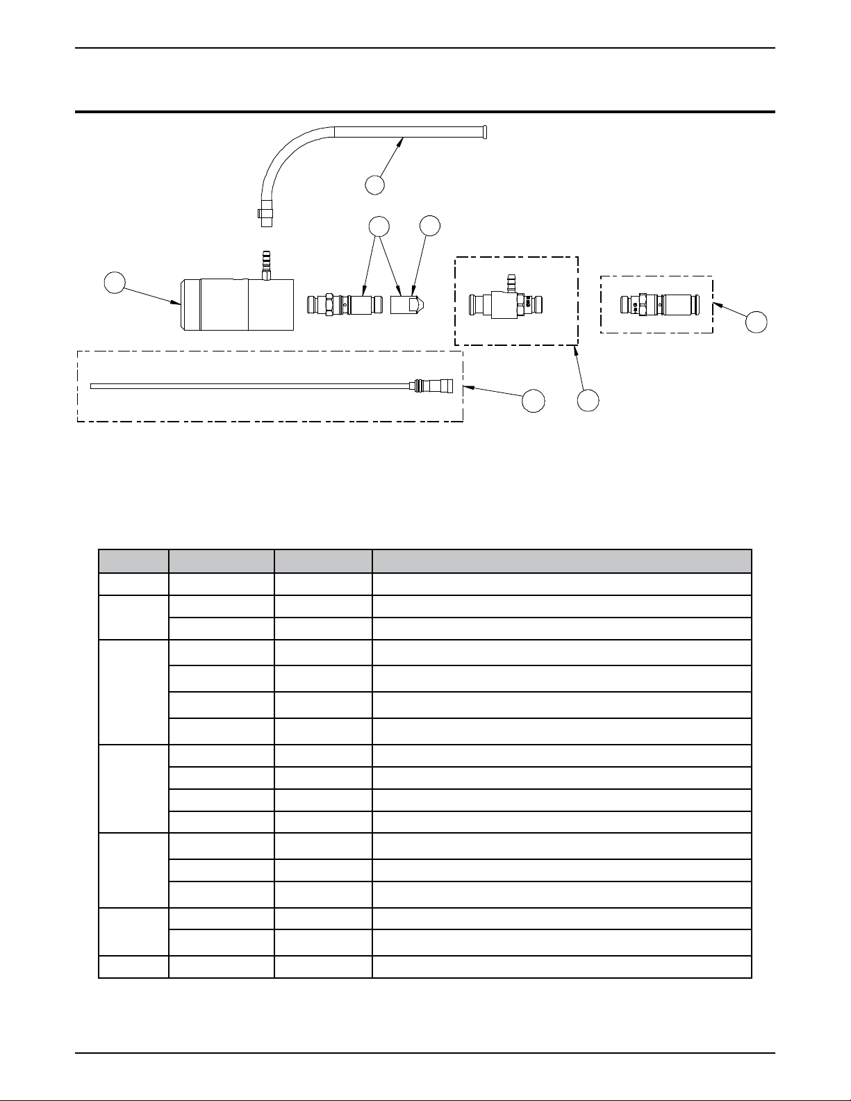
Figure 1A: QFA600 Air-Cooled Torch Package
Item No. Description Qty.
1
2 R45-116-1 Conduit Liner 1 ea.
3 Tweco® Rear Connector Plug 1 ea.
4 Lincoln® Rear Connector Plug 1 ea.
5 Installation Package With Tools 1 ea.
QFA600 Torch Body With Purge Hose & Miller® Rear
Connector Plug
1 ea.
SM-QFDP
Figure 1B: QFW600 Water-Cooled Torch Package
Item No. Description Qty.
1
QFA600 Torch Body With Purge Hose & Miller® Rear
Connector Plug
1 ea.
2 R45-116-1 Conduit Liner 1 ea.
3 Tweco® Rear Connector Plug 1 ea.
4 Lincoln® Rear Connector Plug 1 ea.
5 Installation Package with Tools 1 ea.
6 Quick Hose Water Connectors 1 kit
1-5
INTRODUCTION AND DESCRIPTION
Page 10

quick fixed automation direct plug torches
SECTION 3:
INSTALLATION AND OPERATION
3.01 Installation
1. Remove the torch assembly from the carton.
2. Check to ensure all items, shown in Figure 1A or 1B are
located and identified. If any of the component parts
are missing, please notify the local Tweco Welding
Distributor or Tweco® Products Customer Service
Department at 1-800-426-1888.
®
3. The torch assembly comes with the Miller
connector plug installed. If the feeder requires a
different rear connector plug, select the correct rear
connector plug for the feeder being used and thread
the plug into the rear of the cable assembly. This
connection should be wrench tight.
4. The QF Series torch assemblies are furnished with
R45-116 conduit and the rear connector plugs to fit
this series of conduit. If a different conduit and rear
connector plug is required, refer to Section 5, page
5-9 and 5-10, listing the various conduits that are
available.
5. Remove the conduit from the package.
rear
8. When the conduit is completely through the torch
assembly, seat the brass conduit stop firmly against
the connector plug.
9. Tighten the set screw on the Tweco
or Lincoln® rear connector plug. For Miller® style rear
connector plug, re-install the threaded connector plug
nipple. This connection should be wrench tight.
10. Locate the hole in the torch case providing access
to the conductor tube locking set screw. Insert the
factory supplied 5/32” T-handle allen wrench into the
set screw and rotate counterclockwise until it stops.
Refer to Figure 3.
®
, Panasonic®, and/
CAUTION
Bending or distorting the conduit can cause
wire feed problems.
6. Loosen the set screw located on the Tweco, Panasonic®
and Lincoln® rear connector plug to ensure the conduit
will feed through properly. For Miller® style plug,
remove the threaded connector plug nipple from the
rear connector plug on the torch assembly. Refer to
Figure 2A & 2B.
Figure 2A: Conduit Installation With Set Screw
SET SCREW (5/32” ALLEN KEY)
Figure 3: Conductor Tube Locking Set Screw
11. Remove the gas diffuser, tip and nozzle from the
conductor tube assembly.
12. Insert the conductor tube assembly into the torch
block assembly. The conductor tube is positively
located into the torch body by the use of two stainless
steel alignment pins.
13. Push the conductor tube assembly into place until the
stainless steel set screw can drive the back plug on
the conductor tube into its locked operating position.
The conductor tube has a machined locating groove
around its rear diameter. This groove will be flush with
the front housing when properly installed as shown
in Figure 4.
WHEN CONDUCTOR TUBE IS FULLY
SEATED, GROOVE ON TUBE SHOULD
LINE UP WITH EDGE OF INSULATING
SLEEVE.
®
Figure 2B: Conduit Installation With Plug Nipple (Miller
Style)
Figure 4: Conductor Tube Installation
7. Insert the exposed raw coil end of the conduit, factory
supplied, into the rear connector plug. Feed the
conduit through the torch assembly.
SM-QFDP
INSTALLATION AND OPERATION
3-6
Page 11

quick fixed automation direct plug torches
A
14. If the torch being installed is a water-cooled QFW
series, refer to Section 4 for further instructions on
water supply requirements.
15. Trim the conduit extending from the front of the
conductor tube assembly by following the steps
below:
Method “A” – Using a tape measure or scale, mark
and cut the conduit to the cut length noted in the
table below. Refer to Figure 5 — Method “A”.
Method “B” – The diffusers have a machined
groove around the outer diameter. Position the
diffuser as shown in Figure 5 — Method “B” and
mark and cut the conduit.
Conductor Tube Assembly Cut Length “A”
QTR66 Series (For use with QFA)
QTRW63 Series (For use with QFA)
QTRW64 Series (For use with QFA)
QTRW66 Series (For use with QFA)
METHOD “A”
1-5/16”
(33,32mm)
15/16”
(23,80mm)
1/4” (6,35mm)
5/16”
(7,92mm)
METHOD “B”
3.03 Water-Cooled Torch Assembly
The water-cooled torch assemblies incorporate water
shut-off valves allowing the conductor tube to be removed
without shutting off the water supply. This reduces the
chance of introducing moisture into the conductor tube
and conduit. Refer to Figure 6 showing the water shut-off
valves on the QFW series torch assembly.
VALVE
SPRING
WATER
PLUG
Figure 6: QFW 600 Check Valves
1. A water supply providing not less than 3/4 gallons/
minute (2.84 liters/minute) water flow must be
used during operation. The water supply should be
installed to run when the power source is turned “on”
if possible.
2. Connect the water hose labeled “Water-In” on the torch
assembly to the “Water-Out” of the water supply.
3. Connect the water hose labeled “Water-Out” on
the torch assembly to the “Water-In” of the water
supply.
CUT LINE
Figure 5: Conduit Cut Length
16. After trimming to length, radius and remove any
obstructions from the end of the conduit.
17. Re-install the diffuser, tip and nozzle into the conductor
tube assembly.
18. Install the rear connector plug into the feeder.
19. The torch assembly is furnished with a purge hose
than can be used to supply inert gas and or anti-spatter
through the torch block and conductor tube assembly.
To use this purge hose, remove the plastic plug and
connect accordingly.
20. The torch is now ready to place into operation.
3.02 Disassembly
1. To disassemble the torch assembly, reverse the steps
noted in Section 3.
SM-QFDP
3-7
INSTALLATION AND OPERATION
Page 12

quick fixed automation direct plug torches
SECTION 4:
MAINTENANCE
Contact tips and nozzles should be cleaned frequently. Spatter buildup may cause bridging between nozzle and tip. This
could cause electrical shorting between the nozzle and work piece as well as restricting gas flow.
Regularly inspect the conductor tube, torch and cable assembly for abrasions, cuts, and undue wear. Replace or repair
any parts as needed.
The torch and conductor tube assemblies have o-rings for seals. Lubrication of these o-rings should be done periodically
and periodical inspections should be made to ensure that the o-rings do not de-grade, allowing water and/or shielding
gas leaks to occur. When removing the conductor tube from the torch assembly, be sure the single o-ring located in
the bottom of the hole remains in place.
Problem Possible Cause Corrective Action
1. Loose drive Rollers on feeder. 1. Tighten drive rollers.
2. Dirty or plugged conduit. 2. Replace conduit.
3. Conduit pulled back from diffuser. 3. Reposition conduit and tighten front
screw.
4. Sharp bends or kinks in conduit. 4. Remove and replace conduit.
Wire feed
inconsistent or
not smooth.
Torch assembly
is running hot.
Porous weld.
5. Machine improperly adjusted. 5. Reset machine per machine and wire
manufacturers’ recommendations.
6. Spatter buildup on end of contact tip. 6. Clean or replace contact tip.
7. Loose contact tip or diffuser. 7. Tighten contact tip and diffuser pliers
tight.
8. Excessively worn contact tip. 8. Replace contact tip.
9. Loose ground cable or ground clamp. 9. Tighten or replace as required.
1. Loose power connection. 1. Inspect complete torch and cable for loose
connections and tighten.
2. Loose or undersize ground cable or ground
clamp.
3. Conductor tube not tight in torch block. 3. Tighten stainless setscrew in torch block.
4. Loose contact tip or diffuser. 4. Tighten contact tip and diffuser.
5. Operating torch and conductor tube assembly
above recommended amperage rating.
6. Restricted water flow (only QRW and QRWA
series torch).
1. Poor or improper gas flow. 1. Check gas flow out of conductor tube
2. Moisture from torch/conductor tube. 2. Check o-rings on conductor tube and
3. Dirty or contaminated wire. 3. Change wire.
4. Base metal contamination. 4. Replace base metal.
2. Tighten or replace as required.
5. Readjust machine to correct setting for size
of torch being used.
6. Inspect water lines for any excessive
bends.
nozzle. Check for leaks or restrictions in
gas hoses and connections.
torch block. Check the torch block for any
scarring, gouges to the surface.
SM-QFDP
INSTALLATION AND OPERATION
4-8
Page 13
quick fixed automation direct plug torches
1
2
3
7
6
54
SECTION 5:
REPLACEMENT PARTS
Replacement Parts: QFA600
Item No. Part No. Stock No. Description
1 QFA600BC 3045-1154 Air-cooled Block Cartridge
2
3
4
5
6
7 QF600PH 3045-1246 Purge Hose Assembly (Includes Hose Clamp)
QFA600 Air-Cooled Torch
R176MH 2060-2184 Miller® Connector Plug (Includes Item #3) ***
R174MH 2035-2109 Miller® Connector Plug (Includes Item #3)
R175M-N045 2050-2181 Miller® Plug Nipple, .045” (1,0mm) Wire Use with R176MH
R174M-N045 2040-2192 Miller® Plug Nipple, .045” (1,0mm) Wire Use with R174MH
R175M-N116 2050-2182 Miller® Plug Nipple, .062” (1,6mm) Wire Use with R176MH
R174M-N116 2040-2191 Miller® Plug Nipple, .062” (1,6mm) Wire Use with R174MH
R45-3545-1 1450-1023 R45 Series Conduit Liner
R45-116-1 1450-1028 R45 Series Conduit Liner ***
R44-3545-1 1440-1223 R44 Series Conduit Liner
R44-116-1 1440-1228 R44 Series Conduit Liner
QTR176LH 2086-2624 Lincoln® Connector Plug (2.71” – 68,83mm OAL) ***
EL176LH 2060-2680 Lincoln® Connector Plug (3.84” – 97,54mm OAL)
QTR174LH 2086-2623 Lincoln® Connector Plug (Uses R44 Series Conduit)
176S-H 2060-2177 Tweco Connector Plug ***
350-174H 2035-2110 Tweco Connector Plug (Uses R44 Series Conduit)
SM-QFDP
*** Standard on all QFA Series Torch Body Assembly
5-9
REPLACEMENT PARTS
Page 14

quick fixed automation direct plug torches
1
2
3
7
8
9
10
6
5
4
QFW600 Water-Cooled Torch
Replacement Parts: QFW600
Item No. Part No. Stock No. Description
1 QFW600BC 3045-1386 Water-cooled Block Cartridge
2
3
4
5
R176MH 2060-2184 Miller® Connector Plug (Includes Item #3) ***
R174MH 2035-2109 Miller® Connector Plug (Includes Item #3)
R175M-N045 2050-2181 Miller® Plug Nipple, .045” (1,0mm) Wire Use with R176MH
R174M-N045 2040-2192 Miller® Plug Nipple, .045” (1,0mm) Wire Use with R174MH
R175M-N116 2050-2182 Miller® Plug Nipple, .062” (1,6mm) Wire Use with R176MH
R174M-N116 2040-2191 Miller® Plug Nipple, .062” (1,6mm) Wire Use with R174MH
R45-3545-1 1450-1023 R45 Series Conduit Liner
R45-116-1 1450-1028 R45 Series Conduit Liner ***
R44-3545-1 1440-1223 R44 Series Conduit Liner
R44-116-1 1440-1228 R44 Series Conduit Liner
QTR176LH 2086-2624 Lincoln® Connector Plug (2.71” – 68,83mm OAL) ***
EL176LH 2060-2680 Lincoln® Connector Plug (3.84” – 97,54mm OAL)
QTR174LH 2086-2623 Lincoln® Connector Plug (Uses R44 Series Conduit)
6
7 QF600PH 3045-1246 Purge Hose Assembly (Includes Hose Clamp)
8 QFW600-WO 3045-1324 Water Hose – OUT (Includes Hose Clamp)
9 QFW600-WI 3045-1323 Water Hose – IN (Includes Hose Clamp)
10 400LK-QC 2044-2000 Quick Connector Male & Female
176S-H 2060-2177 Tweco Connector Plug ***
350-174H 2035-2110 Tweco Connector Plug (Uses R44 Series Conduit)
*** Standard on all QFW Series Torch Body Assembly
SM-QFDP
REPLACEMENT PARTS
5-10
Page 15

quick fixed automation direct plug torches
STATEMENT OF WARRANTY
LIMITED WARRANTY: THERMADYNE® warrants that its products will be free of defects in workmanship or material.
Should any failure to conform to this warranty appear within the time period applicable to the THERMADYNE products
as stated below, THERMADYNE shall, upon notification thereof and substantiation that the product has been stored,
installed, operated, and maintained in accordance with THERMADYNE’s specifications, instructions, recommendations
and recognized standard industry practice, and not subject to misuse, repair, neglect, alteration, or accident, correct
such defects by suitable repair or replacement, at THERMADYNE’s sole option, of any components or parts of the
product determined by THERMADYNE to be defective.
THIS WARRANTY IS EXCLUSIVE AND IS IN LIEU OF ALL OTHER WARRANTIES, EXPRESS OR IMPLIED, INCLUDING
ANY WARRANTY OF MERCHANTABILITY OR FITNESS FOR A PARTICULAR PURPOSE.
LIMITATION OF LIABILITY: THERMADYNE shall not under any circumstances be liable for special or consequential
damages, such as, but not limited to, damage or loss of purchased or replacement goods, or claims of customers of
distributor (hereinafter the “Purchaser”) for service interruption. The remedies of the Purchaser set forth herein are
exclusive and the liability of THERMADYNE with respect to any contract, or anything done in connection therewith such
as the performance or breach thereof, or from the manufacture, sale, delivery, resale, or use of any goods covered by or
furnished by THERMADYNE whether arising out of contract, negligence, strict tort, or under any warranty, or otherwise,
shall not, except as expressly provided herein, exceed the price of the goods upon which such liability is based.
THIS WARRANTY BECOMES INVALID IF REPLACEMENT PARTS OR ACCESSORIES ARE USED WHICH MAY IMPAIR
THE SAFETY OR PERFORMANCE OF ANY THERMADYNE PRODUCT.
THIS WARRANTY IS INVALID IF THE PRODUCT IS SOLD BY NON-AUTHORIZED PERSONS.
This warranty is effective for the time stated in the Warranty Schedule beginning on the date that the authorized
distributor delivers the products to the Purchaser.
Warranty repairs or replacement claims under this limited warranty must be submitted by an authorized THERMADYNE
repair facility within thirty (30) days of the repair. No transportation costs of any kind will be paid under this warranty.
Transportation charges to send products to an authorized warranty repair facility shall be the responsibility of the
Purchaser. All returned goods shall be at the Purchaser’s risk and expense. This warranty supersedes all previous
THERMADYNE warranties.
SM-QFDP
6-11
Page 16

quick fixed automation direct plug torches
WARRANTY SCHEDULE
The warranty is effective below for the time stated in the Warranty Schedule beginning on the date that the authorized
distributor delivers the products to the purchaser. THERMADYNE® reserves the right to request documented evidence
of date of purchase.
Engine Driven Welders Parts / Labor
Original Main Power Stators and Inductors 3 years / 3 years
Original Main Power Rectifiers, Control P.C. Boards 3 years / 3 years
All Other Original Circuits and Components Including, but not Limited to, Relays, Switches, Contactors, Solenoids, Fans, Power Switch Semi-Conductors 1 year / 1 year
Engines and Associated Components are NOT Warranted by Thermal Arc®, Although Most are Warranted by the Engine Manufacturer. SEE THE ENGINE
MANUFACTURERS’ WARRANTY FOR DETAILS.
Fabricator® 131, 181, 190, 210, 251, 281; Fabstar® 4030; PowerMaster® 350, 350P, 500, 500P; Excel-Arc® 6045; Wire Feeders: Ultrafeed®, Porta-feed®
Original Main Power Transformer and Inductor 5 years / 3 years
Original Main Power Rectifiers, Control P.C. Boards, Power Switch Semi-Conductors 3 years / 3 years
All Other Original Circuits and Components Including, but not Limited to, Relays, Switches, Contactors, Solenoids, Fans, Electric Motors 1 year / 1 year
160TS, 300TS, 400TS, 185AC/DC, 200AC/DC, 300AC/DC, 400GTSW, 400MST, 300MST, 400MSTP
Original Main Power Magnetics 5 years / 3 years
Original Main Power Rectifiers, Control P.C. Boards, Power Switch Semi-Conductors 3 years / 3 years
All Other Original Circuits and Components Including, but not Limited to, Relays, Switches, Contactors, Solenoids, Fans, Electric Motors 1 year / 1 year
Original Main Power Magnetics 5 years / 3 years
Original Main Power Rectifiers, Control P.C. Boards, Power Switch Semi-Conductors 3 years / 3 years
Welding Console, Weld Controller, Weld Timer 3 years / 3 years
All Other Original Circuits and Components Including, but not Limited to, Relays, Switches, Contactors, Solenoids, Fans, Electric Motors, Coolant Recirculators 1 year / 1 year
Original Main Power Magnetics 1 year / 1 year
Original Main Power Rectifiers, Control P.C. Boards 1 year / 1 year
All Other Original Circuits and Components Including, but not Limited to, Relays, Switches, Contactors, Solenoids, Fans, Power Switch Semi-Conductors 1 year / 1 year
Original Main Power Magnetics 5 years / 3 years
Original Main Power Rectifiers, Control P.C. Boards 3 years / 3 years
All Other Original Circuits and Components Including, but not Limited to, Relays, Switches, Contactors, Solenoids, Fans, Power Switch Semi-Conductors 1 year / 1 year
Water Recirculators 1 year / 1 year
Plasma Welding Torches 180 days / 180 days
Gas Regulators (Supplied with Power Sources) 180 days / NA
MIG and TIG Torches (Supplied with Power Sources) 90 days / NA
Replacement Repair Parts 90 days / NA
MIG, TIG and Plasma Welding Torch Consumable Items NA / NA
Victor® Professional 5 years / NA
Oxygen Conservers 2 years / NA
Aluminum Cylinders Lifetime / NA
Cutting Machine Motors 1 year / NA
HP&I Brass Regulators/Manifolds 2 years / NA
HP&I Stainless Regulators/Manifolds 1 year / NA
HP&I Corrosive Gas Regulators/Manifolds 90 days / NA
TurboTorch® 3 years / NA
CutSkill® 2 years / NA
Steel Cylinders 1 year / NA
Victor Medical 6 years / NA
Victor VSP 2 years / NA
Firepower® MIG Welders 5-2-1 years / NA
Transformers 5 years / NA
Parts Used in Rental Applications 1 year from date sold by seller to authorized
Arcair® N6000 90 days / NA
Eliminator® Spool and Pull Guns 90 days / NA
Robotic Deflection Mounts 90 days / NA
QRM-100 Anti-Spatter Applicator 90 days / NA
TC and TCV Water Coolers 1 year / NA
TSC-96 Smoke Collector 1 year / NA
ESG-1, EPG-CR1, EPG-CR2 Control Boxes for Eliminator Spool & Pull Guns 1 year / NA
QRC-2000 Nozzle Cleaning Stations 1 year / 1 year
All other products 30 days from date purchaser purchases from seller. 30 days / NA
Automated Plasma 2 years / 1 year
CutMaster™ 3 years / 3 years
PakMaster® XL PLUS 3 years / 1 year
Drag-Gun® 1 year / 1 year
Drag-Gun Plus 2 years / 1 year
Torches 1 year / 1 year
Consoles, Control Equipment, Heat Exchangers and Accessory Equipment 1 year / 1 year
GTAW (TIG) & Multi-process Inverter Welding Equipment Parts / Labor
Scout®, Raider®, Explorer™
See the Engine Manufacturers’ Warranty
GMAW/FCAW (MIG) Welding Equipment Parts / Labor
Plasma Welding Equipment Parts / Labor
Ultima® 150
SMAW (Stick) Welding Equipment Parts / Labor
Dragster™ 85
160S, 300S, 400S
General Arc Equipment Parts / Labor
Gas Welding and Cutting Equipment Parts / Labor
MIG Torches and Arc Accessories Parts / Labor
Plasma Cutting Systems Parts / Labor
for Details
distributor
SM-QFDP
6-12
Page 17

GLOBAL CUSTOMER SERVICE CONTACT INFORMATION
Thermadyne USA
2800 Airport Road
Denton, TX 76207 USA
Telephone: (1) 800-535-1888
Fax: (1) 800-535-0557
Thermadyne Canada
2070 Wyecroft Road
Oakville, Ontario
Canada, L6L5V6
Telephone: (1) 905-827-9777
Fax: (1) 905-827-9797
Thermadyne Europe
Europe Building
Chorley North Industrial Park
Chorley, Lancashire
England, PR6 7Bx
Telephone: (44) 1257-261755
Fax: (44) 1257-224800
Thermadyne Asia Sdn Bhd
Lot 151, Jalan Industri 3/5A
Rawang Integrated Industrial Park - Jln Batu Arang
48000 Rawang Selangor Darul Ehsan
West Malaysia
Telephone: 603+ 6092 2988
Fax : 603+ 6092 1085
Cigweld Australia
71 Gower Street
Preston, Victoria
Australia, 3072
Telephone: 1300-654-674
Fax: 613+ 9474-7391
Thermadyne Italy
OCIM, S.r.L.
Via Benaco, 3
20098 S. Giuliano
Milan, Italy
Tel: (39) 02-98 80320
Fax: (39) 02-98 281773
Thermadyne China
RM 102A
685 Ding Xi Rd
Chang Ning District
Shanghai, PR, 200052
Telephone: 86 21+6280-1273
Fax: 86 21+3226-0955
Thermadyne International
2070 Wyecroft Road
Oakville, Ontario
Canada, L6L5V6
Telephone: (1) 905-827-9777
Fax: (1) 905-827-9797
Page 18

World Headquarters
Thermadyne Holdings Corporation
Suite 300, 16052 Swingley Ridge Road
St. Louis, MO 63017
Telephone: (636) 728-3000
Fascimile: (636) 728-3010
www.thermadyne.com
 Loading...