

Tweco PMP3503545, PMPX3333545, PMPS3333545, PMPS3503545, PMPX3503545 Safety And Operating Instructions Manual
...Page 1

Issue Date: April 3, 2009
Manual No: 89200008 Revision: A
SAFETY AND OPERATING
INSTRUCTIONS
PullMaster
™
MIG GUN
English
Français
Español
AIR-COOLED
PMP SERIES
PMPS SERIES
300 AMP
Page 2

WE APPRECIATE YOUR BUSINESS!
Congratulations on your new Tweco® product. We are proud to have
you as our customer and will strive to provide you with the best service
and reliability in the industry. This product is backed by our extensive
warranty and worldwide service network. To locate your nearest
distributor or service agency call 800-426-1888, or visit us on the web at
www.tweco.com.
This Manual has been designed to instruct you on the correct
installation and use of your Tweco® product. Your satisfaction with
this product and its safe operation is our ultimate concern. Therefore,
please take the time to read the entire manual, especially the Safety
Precautions. They will help you to avoid potential hazards that may
exist when working with this product.
YOU ARE IN GOOD COMPANY!
The Brand of Choice for Contractors and Fabricators Worldwide.
Tweco® is a Global Brand of Welding Products for Thermadyne
Industries Inc. We manufacture and supply to major welding industry
sectors worldwide, including: Manufacturing, Construction, Mining,
Automotive, Aerospace, Engineering, Rural and DIY/Hobbyist.
We distinguish ourselves from our competition through marketleading, dependable products that have stood the test of time. We
pride ourselves on technical innovation, competitive prices, excellent
delivery, superior customer service and technical support, together
with excellence in sales and marketing expertise.
Above all, we are committed to develop technologically advanced
products to achieve a safer working environment within the welding
industry.
Page 3

i
WARNINGS
Read and understand this entire Manual and your employer’s safety practices
before installing, operating, or servicing the equipment. While the information
contained in this Manual represents the Manufacturer’s judgment, the Manufacturer
assumes no liability for its use.
PullMaster MIG Gun
Safety and Operating Instructions
Instruction Guide Number 89200008
Published by:
Thermadyne® Industries, Inc.
2800 Airport Rd.
Denton, TX. 76207
(940) 566-2000
www.tweco.com
U.S. Customer Care: (800) 426-1888
International Customer Care: (940) 381-1212
Copyright © 2009 Thermadyne Industries, Inc. All rights reserved.
Reproduction of this work, in whole or in part, without written permission of the publisher is
prohibited.
The publisher does not assume and hereby disclaims any liability to any party for any loss
or damage caused by any error or omission in this Manual, whether such error results from
negligence, accident, or any other cause.
Publication Date: April 3, 2009
Record the following information for Warranty purposes:
Where Purchased:
Purchase Date:
Equipment Serial #:
Page 4

ii
Table of Contents
SECTION 1: INTRODUCTION .................................................................................. 1-1
1.01 How to Use this Manual ................................................................1-1
1.02 Receipt of Equipment ....................................................................1-1
1.03 Description ....................................................................................1-1
SECTION 2: SAFETY PRECAUTIONS .....................................................................
2-2
2.01 Mesures de sécurité ......................................................................2-5
2.02 Precauciones de seguridad ...........................................................2-8
SECTION 3: MIG GUN SPECIFICATIONS............................................................... 3-11
3.01 MIG Gun Part Number Identification ...........................................3-11
SECTION 4: MIG GUN INSTALLATION .................................................................. 4-12
4.01 Standard Setup ...........................................................................4-12
4.02 Standard PullMaster with Other Feeders .....................................4-14
4.03 Calibration ...................................................................................4-15
SECTION 5: SMART GUN FEATURES ...................................................................5-16
5.01 Settings and Controls ..................................................................5-16
SECTION 6: MANUAL GMAW WELDING ..............................................................6-17
6.01 Types of Weld Transfer Modes ....................................................6-17
6.02 Holding and Manipulating the Torch ...........................................6-18
SECTION 7: CONTACT TIP ................................................................................... 7-20
7.01 Contact Tip Identification and Parts List......................................7-20
7.02 Contact Tip Replacement ............................................................7-20
SECTION 8: WIRE CONDUIT ................................................................................. 8-21
8.01 Conduit Identification and Parts List ...........................................8-21
8.02 Conduit Removal .........................................................................8-21
8.03 Conduit Installation .....................................................................8-22
8.04 Jump Liner Installation ...............................................................8-24
8.05 Liner Guide Assembly Replacement ............................................8-25
SECTION 9: CONDUCTOR TUBES ......................................................................... 9-26
SECTION 10: NOZZLES ........................................................................................ 9-26
SECTION 11: REPLACING PCB ASSEMBLY (SMART GUN) ................................ 11-27
SECTION 12: TROUBLESHOOTING .....................................................................12-29
SECTION 13: REPLACEMENT PARTS ................................................................. 13-30
SECTION 14: STATEMENT OF WARRANTY ........................................................ 14-32
14.01 Warranty Schedule ....................................................................14-33
Page 5

safety and operating instructions
1-189200008
Introduction
SECTION 1:
INTRODUCTION
1.01 HOW TO USE THIS MANUAL
To ensure safe operation, read the entire manual, including the chapters on safety instructions
and warnings.
Throughout this manual, the words WARNING, CAUTION, and NOTE may appear. Pay particular
attention to the information provided under these headings. These special annotations are
easily recognized as follows:
NOTE
NOTE conveys installation, operation, or maintenance information which is
important but not hazard-related.
CAUTION
CAUTION indicates a potentially hazardous situation which, if not avoided, may
result in injury.
WARNING
WARNING indicates a potentially hazardous situation which, if not avoided, could
result in death or serious injury.
1.02 RECEIPT OF EQUIPMENT
When you receive the equipment, check it against the invoice to make sure it is complete and
inspect the equipment for possible damage due to shipping. If there is any damage, notify the
carrier immediately to file a claim. Furnish complete information concerning damage claims
or shipping errors to the location in your area, listed on the back cover of this manual. Include
a full description of the parts in error.
If you want additional or replacement copies of this manual, please contact Tweco® at the
address and phone number in your area listed on the back cover of this manual. Include the
Manual number (from page i)
1.03 DESCRIPTION
The Tweco® PullMaster guns are 300 AMP, pistol-grip pull guns that are designed to be used
in conjunction with the Thermal Arc PowerMaster SP welding utilize a power sourcea and wire
feed system. The PullMaster guns are available in 2 versions standard, and with smart controls.
The smart control will allow for welding current, material thickness, wire feed speed, and arc
length trim adjustments on the gun via a digital display board.
Page 6

2-2
safety and operating instructions
89200008Safety Precautions
SECTION 2:
SAFETY PRECAUTIONS
WARNING
SERIOUS INJURY OR DEATH may result if welding and cutting equipment is not
properly installed, used, and maintained. Misuse of this equipment and other
unsafe practices can be hazardous. The operator, supervisor, and helper must read
and understand the following safety warnings and instructions before installing
or using any welding or cutting equipment, and be aware of the dangers of the
welding or cutting process. Training and proper supervision are important for a
safe work place. Keep these instructions for future use. Additional recommended
safety and operating information is referenced in each section.
WARNING
This product contains chemicals, including lead, or otherwise produces
chemicals known to the State of California to cause cancer, birth defects and
other reproductive harm. Wash hands after handling.
(California Health & Safety Code § 25249.5 et seq.)
ELECTRIC SHOCK CAN CAUSE INJURY OR DEATH
Install and maintain equipment in accordance with the National Electrical Code
(NFPA 70) and local codes. Do not service or repair equipment with power on.
Do not operate equipment with protective insulators or covers removed. Service
or repair to equipment must be done by qualified and/or trained
personnel only.
Do not contact electrically live parts. Always wear dry welding gloves that are in good condition.
Aluminized, protective clothing can become part of the electrical path. Keep oxygen cylinders,
chains, wires, ropes, cranes, and hoists away from any part of the electrical path. All ground
connections must be checked periodically to determine if they are mechanically strong, and
electrically adequate for the required current. When engaged in AC welding/cutting under wet
conditions or where perspiration is a factor, the use of automatic controls for reducing the no
load voltage is recommended to reduce shock hazards. Accidental contact must be prevented
when using open circuit voltage exceeding 80 volts AC, or 100 volts DC by adequate insulation
or other means. When welding is to be suspended for any length of time, such as during lunch
or overnight, all electrode holders and electrodes should be removed from the electrode holder
and the power supply should be turned off to prevent accidental contact. Keep MIG Guns,
electrode holders, Tig torches, Plasma torches, and electrodes away from moisture and water.
See safety and operating references 1, 2, and 8.
Page 7

safety and operating instructions
2-389200008
SMOKE, FUMES, AND GASES CAN BE DANGEROUS TO YOUR HEALTH
Ventilation must be adequate to remove smoke, fumes, and gases during operation
to protect operators and others in the area. Vapors of chlorinated solvents can
form the toxic gas “Phosgene” when exposed to ultraviolet radiation from an
electric arc. All solvents, degreasers, and potential sources of these vapors must
be removed from the operating area. Use air-supplied respirators if ventilation
is not adequate to remove all fumes and gases. Oxygen supports, and vigorously accelerates fire
and should never be used for ventilation.
See safety and operating references 1, 2, 3, and 4.
ARC RAYS, HOT SLAG, AND SPARKS CAN INJURE EYES AND BURN SKIN
Welding and cutting processes produce extreme localized heat and strong
ultraviolet rays. Never attempt to weld/cut without a federally compliant welding
helmet with the proper lens. A number 12 to 14 shade filter lens provides the
best protection against arc radiation. When in a confined area, prevent the
reflected arc rays from entering around the helmet. Approved shielding curtains
and appropriate goggles should be used to provide protection to others in the surrounding area.
Skin should be protected from arc rays, heat, and molten metal. Always wear protective gloves
and clothing. All pockets should be closed and cuffs sewn shut. Leather aprons, sleeves, leggings,
etc. should be worn for out-of-position welding and cutting, or for heavy operations using large
electrodes. Hightop work shoes provide adequate protection from foot burns. For added protection,
use leather spats. Flammable hair preparations should not be used when welding/cutting. Wear
ear plugs to protect ears from sparks. Where work permits, the operator should be enclosed in
an individual booth painted with a low reflective material such as zinc oxide.
See safety and operating references 1, 2, and 3.
WELDING SPARKS CAN CAUSE FIRES AND EXPLOSIONS
Combustibles reached by the arc, flame, flying sparks, hot slag, and heated
materials can cause fire and explosions. Remove combustibles from the work
area and/or provide a fire watch. Avoid oily or greasy clothing as a spark may
ignite them. Have a fire extinguisher nearby, and know how to use it. If welding/
cutting is to be done on a metal wall, partition, ceiling, or roof, precautions must
be taken to prevent ignition of nearby combustibles on the other side. Do not
weld/cut containers that have held combustibles. All hollow spaces, cavities, and containers
should be vented prior to welding/cutting to permit the escape of air or gases. Purging with inert
gas is recommended. Never use oxygen in a welding torch. Use only inert gases or inert gas
mixes as required by the process. Use of combustible compressed gases can cause explosions
resulting in personal injury or death. Arcing against any compressed gas cylinder can cause
cylinder damage or explosion. See safety and operating references 1, 2, 5, 7, and 8.
NOISE CAN DAMAGE HEARING
Noise from the air carbon-arc process can damage your hearing. Wear protective
hearing devices to ensure protection when noise levels exceed OHSA standards.
Adequate hearing protection devices must be worn by operators and surrounding
personnel to ensure personal protection against noise. See safety and operating
references 1, 2, and 6.
Safety Precautions
Page 8

2-4
safety and operating instructions
89200008
SAFETY AND OPERATING REFERENCES
1. Code of Federal Regulations (OSHA) Section 29, Part 1910.95, 132, 133, 134, 139, 251,
252, 253, 254 and 1000. U.S. Government Printing Office, Washington, DC 20402.
2. ANSI Z49.1 “Safety in Welding and Cutting”.
3. ANSI Z87.1 “Practice for Occupational and Educational Eye and Face Protection”.
4. ANSI Z88.2. “Standard Practice for Respiratory Protection”. American National
Standards Institute, 1430 Broadway, New York, NY 10018.
5. AWS F4.1. “Recommended Safe Practices for Welding and Cutting Containers”.
6. AWS C5.3. “Recommended Practices for Air Carbon-Arc Gouging and Cutting”.
The American Welding Society, 550 NW Lejeune Rd., P.O. Box 351040, Miami, FL
33135.
7. NFPA 51B. “Fire Prevention in Cutting and Welding Processes”.
8. NFPA-7. “National Electrical Code”. National Fire Protection Association, Battery Park,
Quincy, MA 02269.
9. CSA W117.2. “Safety in Welding, Cutting and Allied Processes”. Canadian Standards
Association, 178 Rexdale Blvd., Rexdale, Ontario, Canada M9W 1R3.
DECLARATION OF CONFORMITY
Tweco® Products, Inc. declares under our sole responsibility that the product
Hand Held Air/Gas and Water Cooled MIG Welding Torches
To which this declaration relate(s) are in conformance with the following standards:
IEC 60974-7:2005
Following the provisions of the 73/23/EEC directive.
Safety Precautions
Page 9

safety and operating instructions
2-589200008
2.01 MESURES DE SÉCURITÉ
AVERTISSEMENT
DES BLESSURES GRAVES OU MORTELLES
peuvent résulter d’une installation,
d’un usage ou d’un entretien inadéquat de l’équipement de soudage et de
découpage. Une mauvaise utilisation de cet équipement et d’autres pratiques
risquées peuvent être dangereuses. L’opérateur, le superviseur et l’aide doivent
lire et comprendre les avertissements et les instructions de sécurité suivantes
avant d’installer ou d’utiliser tout équipement de soudage ou de découpage et être
conscients des dangers inhérents aux processus de soudage et de découpage.
Une formation et une supervision adaptées sont importantes pour assurer un lieu
de travail sûr. Gardez ces instructions pour une utilisation future. Chaque section
comporte des informations supplémentaires de sécurité et de fonctionnement.
AVERTISSEMENT
Ce produit contient des produits chimiques, comme le plomb, ou engendre
des produits chimiques, reconnus par l’état de Californie comme pouvant
être à l’origine de cancer, de malformations fœtales ou d’autres problèmes
de reproduction. Il faut se laver les mains après toute manipulation.
(Code de Californie de la sécurité et santé, paragraphe 25249.5 et suivants)
UN CHOC ÉLECTRIQUE PEUT CAUSER DES BLESSURES OU LA MORT
L’installation et l’entretien de l’équipement doivent être conformes au Code national
de l’électricité NFPA 70 et aux codes locaux. N’effectuez pas l’entretien ou la
réparation d’équipement en marche. N’opérez pas l’équipement sans isolateurs ou
caches de protection. L’entretien ou la réparation de l’équipement doivent être
effectués uniquement par un technicien qualifié ou par du personnel formé.
Ne touchez pas aux pièces électriques chargées. Portez toujours des gants de soudage au sec
et en bon état. Les vêtements de protection aluminisés peuvent devenir une partie du chemin
électrique. Éloignez les bouteilles d’oxygène, les chaînes, les câbles métalliques, les appareils
de levage, les treuils et les élévateurs de toute partie du circuit électrique. Toutes les liaisons de
terre doivent être vérifiées périodiquement pour déterminer si elles sont solides et appropriées au
courant demandé. En cas de soudage ou de découpage en courant alternatif dans des conditions
d’humidité ou de chaleur où l’opérateur risque de transpirer, il est recommandé d’utiliser des
contrôles automatiques pour réduire la tension à vide et ainsi diminuer les risques de choc
électrique. Lorsque le procédé de soudage et de découpage exige des valeurs de tension en
circuit ouvert dans des machines à courant alternatif supérieur à 80 volts ou dans des machines
à courant continu supérieur à 100 volts, il faut prendre des mesures pour empêcher un contact
accidentel en prévoyant une isolation adéquate ou d autres moyens. Lorsqu’il faut interrompre
les activités de soudage pendant un certain temps, à l’heure du repas ou la nuit, par exemple, il
faut enlever toutes les électrodes du porte-électrode et mettre hors tension l’alimentation pour
éviter tout contact accidentel. Gardez les pistolets Mig, les porte-électrodes, les torches TIG, les
torches à plasma et les électrodes loin de l’humidité et de l’eau. Voir les références en matière
de sécurité et d’utilisation n° 1, 2 et 8.
Mesures de sécurité
Page 10

2-6
safety and operating instructions
89200008
LA FUMÉE, LES ÉMANATIONS ET LES GAZ PEUVENT ÊTRE DANGEREUX POUR VOTRE SANTÉ
La ventilation doit être suffisante pour enlever la fumée, les émanations et les
gaz pendant le fonctionnement de la torche afin protéger les opérateurs et les
autres personnes présentes dans la zone. Les vapeurs de solvants chlorés
peuvent former un gaz toxique appelé « Phosgène » si elles sont exposées au
rayonnement ultraviolet d un arc électrique. Il faut enlever de la zone de travail
tous les solvants, décapants et sources potentielles de ces vapeurs. Servez-vous d’appareils
respiratoires à adduction d’air si la ventilation n’est pas suffisante pour enlever toutes les
émanations et gaz. L’oxygène alimente les incendies et en accélère la propagation il ne faut
jamais l’utiliser à des fins de ventilation. Voir les références en matière de sécurité et
d’utilisation n° 1, 2, 3 et 4.
L LES RAYONS DE L’ARC, LES SCORIES ET LES ÉTINCELLES CHAUDS PEUVENT BLESSER
LES YEUX ET BRÛLER LA PEAU
Les procédés de soudage et de découpage produisent une chaleur extrême
localisée et de puissants rayons ultraviolets. N’essayez jamais de souder ou de
couper sans casque soudage conforme aux normes du gouvernement fédéral et
muni d’une lentille appropriée. Des lentilles à filtre de numéro 12 à 14 fournissent
la meilleure protection contre le rayonnement de l’arc. Dans un endroit confiné,
il faut éviter que les rayons reflétés de l’arc n’entrent autour du casque. Il faut utiliser des rideaux
de protection approuvés et des lunettes de protection appropriées pour protéger les autres personnes
se trouvant aux abords. Il faut aussi protéger la peau nue des rayons de l’arc, de la chaleur et du
métal fondu. Portez toujours des gants et des vêtements de protection. Toutes les poches doivent
être fermées et les manchettes, cousues. Il faut porter un tablier, des manches, des guêtres, etc.
en cuir pour effectuer de soudage ou de découpage et dans le cas des activités intensives nécessitant
de grandes électrodes. Les chaussures de sécurité montantes fournissent une protection suffisante
contre les brûlures aux pieds. Pour obtenir une plus grande protection, portez des guêtres en cuir.
Il ne faut pas utiliser de produits capillaires inflammables avant d’effectuer des activités de soudage
ou de découpage. Portez des bouchons d’oreilles pour vous protéger les oreilles des étincelles.
Lorsqu’il est possible de le faire dans la zone de travail, l’opérateur doit s’isoler dans une cabine
individuelle recouverte d’un revêtement à faible réflectivité, comme l’oxyde de zinc. Voir les
références en matière de sécurité et d’utilisation n° 1, 2 et 3.
LES ÉTINCELLES DE SOUDAGE PEUVENT CAUSER DES INCENDIES ET DES EXPLOSIONS
Les combustibles atteints par l’arc, les flammes, les vols d’étincelles, les scories
chaudes et les matériaux chauffés peuvent causer des incendies et des explosions.
Enlevez les combustibles de la zone de travail ou mettez en place du personnel
de surveillance. Évitez les vêtements huileux ou graisseux, car une étincelle peut
y mettre le feu. Ayez un extincteur à proximité et sachez comment l’utiliser. Si
l’activité de soudage ou de découpage doit être fait contre un mur, une cloison,
un plafond ou un toit, il faut prendre des précautions pour d’enflammer des combustibles qui se
trouveraient à proximité, de l’autre côté. Ne soudez pas et ne coupez pas de conteneurs ayant
contenu des combustibles. Il faut aérer tous les espaces creux, les cavités et les conteneurs avant
de les soumettre au soudage ou au découpage afin d’évacuer tout l’air ou le gaz qui peut s’y
trouver. Il est recommandé d’effectuer une purge avec du gaz inerte. N’utilisez jamais d’oxygène
dans une tête de soudage. N’utilisez que des gaz inertes ou des mélanges de gaz inertes,
conformément aux exigences du procédé. L’utilisation de gaz combustibles comprimés peut
causer des explosions entraînant des blessures ou la mort. Le fait d’utiliser l’arc sur une bouteille
de gaz comprimé peut endommager la bouteille ou causer une explosion. Voir les références
en matière de sécurité et d’utilisation n° 1, 2, 5, 7 et 8.
Mesures de sécurité
Page 11

safety and operating instructions
2-789200008
LE BRUIT PEUT ENDOMMAGER L’OUÏE
Le bruit du procédé de l’arc avec électrode en carbone et jet d’air peut endommager
l’ouïe. Portez un dispositif de protection de l’ouïe pour vous protéger lorsque le
niveau de bruit dépasse les normes de l’OSHA. Les opérateurs et le personnel aux
abords doivent porter un dispositif de protection de l’ouïe approprié pour les protéger
efficacement contre le bruit. Voir les références en matière de sécurité et
d’utilisation n° 1, 2 et 6.
RÉFÉRENCES EN MATIÈRE DE SÉCURITÉ ET D’UTILISATION
1. Code of Federal Regulations (OSHA), section 29, partie 1910.95, 132, 133, 134,
139, 251, 252, 253, 254 et 1000. U.S. Government Printing Office, Washington, DC
20402.
2. ANSI Z49.1 « Safety in Welding and Cutting ».
3. ANSI Z87.1 « Practice for Occupational and Educational Eye and Face Protection ».
4. ANSI Z88.2. « Standard Practice for Respiratory Protection ». American National
Standards Institute, 1430 Broadway, New York, NY 10018.
5. AWS F4.1. « Recommended Safe Practices for Welding and Cutting Containers ».
6. AWS C5.3. « Recommended Practices for Air Carbon-Arc Gouging and Cutting ».
The American Welding Society, 550 NW Lejeune Rd., P.O. Box 351040, Miami, FL
33135.
7. NFPA 51B. « Fire Prevention in Cutting and Welding Processes ».
8. NFPA-7. « National Electrical Code » (code national de l’électricité). National Fire
Protection Association, Battery Park, Quincy, MA 02269.
9. CSA W117.2. « Règles de sécurité en soudage, coupage et procédés connexes ».
Association canadienne de normalisation, 178 boul. Rexdale, Rexdale, Ontario, Canada
M9W 1R3.
DECLARATION OF CONFORMITY
Tweco® Products, Inc. declares under our sole responsibility that the product
Hand Held Air/Gas and Water Cooled MIG Welding Torches
To which this declaration relate(s) are in conformance with the following standards:
IEC 60974-7:2005
Following the provisions of the 73/23/EEC directive.
Mesures de sécurité
Page 12

2-8
safety and operating instructions
89200008
2.02 PRECAUCIONES DE SEGURIDAD
ADVERTENCIA
Se pueden sufrir LESIONES GRAVES O LA MUERTE si el equipo de soldadura
y corte no se instala, utiliza y mantiene debidamente. El uso inadecuado
de este equipo y otras prácticas no seguras pueden ser peligrosos. El operador,
supervisor y ayudante deben leer y comprender las siguientes advertencias e
instrucciones de seguridad antes de instalar o usar cualquier equipo de soldadura
o corte y deberán estar atentos a los peligros del proceso de soldadura y corte. El
entrenamiento y supervisión adecuados son importantes para un lugar de trabajo
seguro. Guarde estas instrucciones para uso futuro. En cada sección se incluyen
otras recomendaciones sobre seguridad y operación.
ADVERTENCIA
Este producto contiene sustancias químicas, dentro de las que se incluye el
plomo, o de otro modo produce sustancias químicas que el Estado de California
sabe que provocan cáncer, defectos congénitos y/u otros daños reproductores.
Lávese las manos después de haber estado en contacto con estas
sustancias.
(Código sobre Salud y Seguridad de California, Sec. 25249.5 y siguientes)
LAS DESCARGAS ELÉCTRICAS PUEDEN CAUSAR HERIDAS O LA MUERTE
Instale y mantenga el equipo de acuerdo al Código Nacional Eléctrico (NFPA 70)
y las normas locales. No realice mantenimiento o reparaciones con el equipo
prendido. No opere equipos sin los aisladores de protección o sin tapas. Los
servicios o reparación de los equipos solamente deben ser ejecutados por personal
calificado o entrenado..
No toque componentes eléctricos mientras están eléctricamente vivos. Siempre use guantes
de soldar secos y en buen estado. La ropa de protección aluminizada puede ser conductora
de la electricidad. Mantenga los tubos de oxígeno, cadenas, cuerdas de alambre, guinchos,
grúas y elevadores fuera del alcance de cualquier parte del circuito eléctrico. Se deben verificar
periódicamente todas las conexiones a tierra para determinar si están mecánicamente firmes y
eléctricamente adecuadas para la tensión requerida. Al trabajar con corriente alterna para soldar
o cortar en condiciones de humedad o en ambientes calurosos donde se transpira copiosamente,
se recomienda utilizar mandos automáticos confiables para reducir el voltaje y así reducir los
riesgos de descarga eléctrica. Se debe evitar cualquier tipo de contacto accidental al utilizar un
voltaje de circuito abierto que supere los 80 VCA o 100 VCC emplazando un aislamiento u otros
medios adecuados. Cuando se tenga que interrumpir la soldadura durante un importante período
de tiempo, como durante el almuerzo o la noche, todos los electrodos deben ser retirados del
portaelectrodos y se debe apagar la alimentación eléctrica de manera que no puedan producirse
contactos accidentales. Evite que las pistolas Mig, los portaelectrodos, los sopletes Tig, los
sopletes de Plasma y los electrodos se vean afectados por la humedad y el agua. Consulte las
referencias de seguridad y uso 1, 2 y 8.
Precauciones de seguridad
Page 13
safety and operating instructions
2-989200008
EL HUMO, LOS VAPORES Y LOS GASES PUEDEN SER PELIGROSOS PARA LA SALUD
La ventilación debe ser adecuada para que salga el humo, los vapores y los
gases durante la operación para proteger a los operadores y al resto del personal
en el área. Los vapores de solventes clorados pueden formar el gas tóxico
“Fosgeno” cuando quedan expuestos a los rayos ultravioletas producidos por
un arco eléctrico. Todos los solventes, desengrasantes y fuentes potenciales de
esos vapores deben ser retirados del área de trabajo. Utilice respiradores con tanque de aire si
la ventilación no resulta adecuada para eliminar todos los humos y gases. El oxígeno sostiene y
acelera vigorosamente el fuego, por lo que nunca debe ser utilizado para ventilación. Consulte
las referencias de seguridad y uso 1, 2, 3 y 4.
LOS RAYOS DEL ARCO, LA ESCORIA CALIENTE Y LAS CHISPAS PUEDEN LASTIMAR LOS OJOS
Y QUEMAR LA PIEL
Los procesos de soldadura y corte producen calor extremadamente localizado
y fuertes rayos ultravioletas. Nunca intente soldar o cortar sin una máscara de
soldadura con lentes adecuados y que cumpla con las exigencias federales. Los
lentes con filtro número 12 a 14 ofrecen la mejor protección contra la radiación
del arco. Cuando trabaje en un área confinada, evite que los rayos reflejados del
arco entren alrededor de la máscara. Se deben usar cortinas de protección y gafas apropiadas
para proteger al personal presente en áreas cercanas. La piel también debe ser protegida de los
rayos del arco, del calor y del metal derretido. Siempre se deberán utilizar guantes y vestimenta
de protección. Todos los bolsillos deben estar cerrados y los dobladillos cosidos. Se deben usar
delantales de cuero, mangas, pantalones, etc., para la soldadura y el corte fuera de posición o
para operaciones pesadas con electrodos grandes. Las botas de trabajo de caña alta ofrecen
protección adecuada contra las quemaduras de los pies. Use protectores de cuero para brazos
y piernas para contar con protección adicional. No se deben usar productos inflamables para el
cabello cuando se suelde o corte. Usar orejeras para proteger las orejas de las chispas. Cuando
el área de trabajo lo permita, el operador debe trabajar dentro de una cabina individual pintada
con una terminación de baja reflexión, como por ejemplo: óxido de zinc. Consulte las referencias
de seguridad y uso 1, 2 y 3.
LAS CHISPAS DE SOLDADURA PUEDEN CAUSAR INCENDIO Y EXPLOSIONES
Los combustibles alcanzados por el arco, por llamas, chispas, escorias o materiales
calientes pueden ser las causas de incendios y explosiones. Retire los combustibles
del área de trabajo u organice una guardia contra incendios. Evite que las ropas
estén sucias con aceite o grasa, ya que una chispa puede encenderlas. Tenga un
extintor de incendios cerca y sepa como usarlo. Si se está soldando o cortando
en una pared, un divisorio, un cielorraso o un techo metálico, se deben tomar
precauciones para evitar la ignición de combustibles que puedan estar del otro lado. No suelde
ni corte recipientes que hayan contenido combustibles. Todos los espacios vacíos, cavidades y
recipientes deben ventilarse antes de soldar o cortar para permitir la salida de aire o gases. Se
recomienda purgarlos con gas inerte. Nunca use oxígeno en un soplete de soldar. Use solamente
gases inertes o mezclas de gases inertes conforme a lo exigido por el proceso. El uso de gases
comprimidos combustibles puede provocar explosiones y causar daños personales o la muerte.
La radiación del arco contra cualquier tubo de gas comprimido puede causarle daños al tubo o
su explosión. Consulte las referencias de seguridad y uso 1, 2, 5, 7 y 8.
Precauciones de seguridad
Page 14

2-10
safety and operating instructions
89200008
EL RUIDO PUEDE DAÑAR LA AUDICIÓN
El ruido del proceso con arco de aire/carbón puede dañar su audición. Use dispositivos
de protección auditiva para contar con protección cuando los niveles superen las
normas de la OSHA. Los operadores y personal próximo deben usar protectores
auriculares para asegurar la protección contra el ruido. Consulte las referencias
de seguridad y uso 1, 2 y 6.
REFERENCIAS DE SEGURIDAD Y USO
1. Código de Normas Federales (OSHA), Sección 29, Partes 1910.95, 132, 133, 134, 139,
251, 252, 253, 254 y 1000. Oficina de la Imprenta Gubernamental de los EE.UU.,
Washington, DC 20402.
2 ANSI Z49.1 “Safety in Welding and Cutting” (Seguridad en la soldadura y el corte).
3. ANSI Z87.1 “Practice for Occupational and Educational Eye and Face Protection” (Práctica
para la protección ocupacional y educativa de ojos y rostro).
4. ANSI Z88.2. “Standard Practice for Respiratory Protection” (Práctica estándar para
protección respiratoria). American National Standards Institute (Instituto norteamericano
de normas nacionales), 1430 Broadway, New York, NY 10018.
5. AWS F4.1. “Recommended Safe Practices for Welding and Cutting Containers” (Prácticas
seguras recomendadas para soldadura y corte de recipientes).
6. AWS C5.3. “Recommended Safe Practices for Air Carbon-Arc Gouging and Cutting”
(Prácticas seguras recomendadas para ranurado y corte con arco de aire/carbón). The
American Welding Society (Sociedad norteamericana de soldadura), 550 NW Lejeune
Rd., P.O. Box 351040, Miami, FL 33135.
7. NFPA 51B. “Fire Prevention in Cutting and Welding Processes” (Prevención de incencios
en procesos de corte y soldadura).
8. NFPA-7. “National Electrical Code” (Código eléctrico nacional). National Fire Protection
Association (Asociación nacional para la protección contra incendios), Battery Park,
Quincy, MA 02269.
9. CSA W117.2. “Safety in Welding, Cutting and Allied Processes” (Seguridad en procesos de
soldadura, corte y asociados). Canadian Standards Association (Asociación canadiense
de normas), 178 Rexdale Blvd., Rexdale, Ontario, Canadá M9W 1R3.
DECLARATION OF CONFORMITY
Tweco® Products, Inc. declares under our sole responsibility that the product
Hand Held Air/Gas and Water Cooled MIG Welding Torches
To which this declaration relate(s) are in conformance with the following standards:
IEC 60974-7:2005
Following the provisions of the 73/23/EEC directive.
Precauciones de seguridad
Page 15

safety and operating instructions
3-1189200008
SECTION 3:
MIG GUN SPECIFICATIONS
3.01 MIG GUN PART NUMBER IDENTIFICATION
NOTE
Tweco® MIG guns, as a general rule, have a specific nomenclature incorporated
within each part number to help determine the wire size of each MIG gun.
Example Part Number:
PMPS3333545
PullMaster, Pull, Smart
300 AMP gun, 33' (10,1M) cable
.035" / .045" (0,9mm / 1,2mm)
Wire Diameter
Abbreviation / Definition
PM PullMaster
P Pull
S Smart Gun
Standard PullMaster Guns
Part No. Stock No. Rating Connection Description
PMP3333545 1027-1401
300A @
80%
Tweco
33 ft. (10,1M)
PMP3503545 1027-1402 50 ft. (15,2M)
Smart PullMaster Guns with Advanced Digital Controls
Part No. Stock No. Rating Connection Description
PMPS3333545 1027-1407
300A @
80%
Tweco
33 ft. (10,1M)
PMPS3503545 1027-1408 50 ft. (15,2M)
Standard Euro PullMaster Guns
Part No. Stock No. Rating Connection Description
PMPX3333545 1027-1404
300A @
80%
Euro-Kwik
33 ft. (10,1M)
PMPX3503545 1027-1405 50 ft. (15,2M)
Smart Euro PullMaster Guns
Part No. Stock No. Rating Connection Description
PMPSX3333545 1027-1410
300A @
80%
Euro-Kwik
33 ft. (10,1M)
PMPSX3503545 1027-1411 50 ft. (15,2M)
MIG Gun Specifications
Page 16

4-12
safety and operating instructions
89200008
SECTION 4:
MIG GUN INSTALLATION
NOTE
Be certain that the end user (welder, operator, or helper) reads and understands
these instructions. Be certain that the welder also reads Section 2, "Safety
Precautions."
WARNING
Electric shock can cause injury or death.
4.01 STANDARD SETUP
Figure 1: Standard MIG Gun Setup
1. Plug the gun connector plug into the
feeder. Tweco plug and Euro-Kwik.
2. Plug the 4-pin Amphenol plug, attached
to the gun, into the 4-pin socket on the
welder.
MIG Gun Installation
Page 17

safety and operating instructions
4-1389200008
3. After inserting a wire inlet guide or
conduit from the MIG Gun, tighten the
brass nut and O-ring seal inside feeder.
If this nut is not tightened, it may cause
gas flow to escape resulting in decreased
gas flow. When removing the inlet guide
or conduit, loosen this nut.
NOTE
DO NOT OVER-TIGHTEN. Ensure that the conduit/liner does not touch or rub
against drive rolls.
4. Adjust the drive roll pressure on the feeder to a minimum, then adjust the drive roll on gun
halfway. If needed, drive roll pressure may be increased on the feeder and pull gun.
NOTE
The tension adjusters on both drive rolls should be set to the minimum setting
when using 3/64" (1,2mm) aluminum. For 1/16" (1,6mm) aluminum, the user
may need to tighten the rolls one or two turns of the adjusting screw.
5. Tighten the wire spool drag to finger tip tight. The spool, when pushed 1/4 turn, should
freely spin one complete rotation.
6. Typically tighten down the idler until it touches the wire, then tighten one to two turns. A
nickel thick-sized gap should be between the tightening knob head and gun handle case.
Do not overtighten because it can cause the motor to stall and gun to stop working.
7. Adjust voltage and wire speed as recommended by the wire manufacturer. (Refer to
table in Section 6.01). Gun is now ready for operation.
NOTE
Do not weld with the gun if the cable is coiled in circles less than 3' in diameter
because this will cause wire feed problems.
NOTE
Wipe off drive rolls with a Scotch Pad between each spool of wire. Lay pad
against roller and push the inch switch button in the feeder cabinet to turn
the rollers.
MIG Gun Installation
Page 18

4-14
safety and operating instructions
89200008
4.02 STANDARD PULLMASTER WITH OTHER FEEDERS
When using the standard PullMaster MIG gun on other feeders, the Control Box (Part No. EPG-CR2,
Stock No. 1028-1291) must be used in combination with the MIG gun. Follow the instructions
noted below and refer to any further instructions included with the EPG-CR2 Control Box.
NOTE
The PullMaster MIG Gun must have a jumper wire with a Tweco, Miller, or Lincoln
connection on one end and spade connections on the other. The PullMaster MIG
Gun must also have jumper wire PMP354T.
1. Connect the jumper wire to the receiver
on the feeder (refer to chart below to find
which jumper wire is needed) and connect
the spade connectors on the other end of
the jumper wire to the spade connector
receiver on the EPG-CR2 box.
2. Connect the PMP354T to the gun and the other end to the amphenol receiver in the
EPG-CR2 box.
3. If using a Feeder other than Tweco, change the rear power plug on the gun to either the
Miller or Lincoln plugs (whichever is needed for the feeder being used).
Jumper wire # Connector Rear Plug # Connector Plug
EPG354T Tweco -- --
EPG354M Miller EPG174MH Miller
EPG354L Lincoln EPG174LH Lincoln
PMP354T Amphenol/Miller EPGHK1 Gas Hook Up Kit
MIG Gun Installation
Page 19
safety and operating instructions
4-1589200008
4.03 CALIBRATION
NOTE
The Thermal Arc SP machine requires calibration EVERYTIME the machine is
turned on while the PullMaster MIG gun is connected or when a different PullMaster
gun is installed.
NOTE
This does not apply to standard MIG guns or PulseMaster guns.
1. Install gun as shown in Section 4.01.
2. Feed wire through gun and tube (drive rolls on gun and machine must be closed).
3. Go to menu on machine and press the up and down arrow keys at the same time.
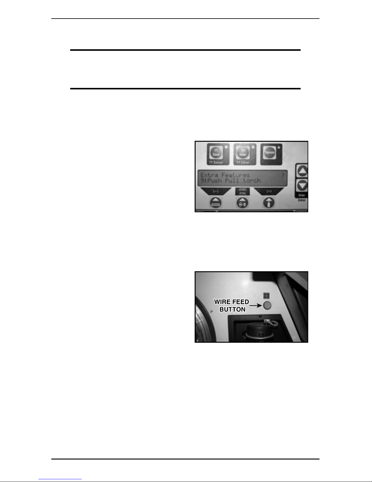
4. Press the
“+” button to scroll to “Extra
Features 9: Push/Pull torch”.
5. Again, press the up and down arrow keys at the same time. You will select which torch
you are using by pressing the “+” button.
6. Press the ‘up’ arrow key; this should bring up a question asking if you want to calibrate.
Press the down arrow stating “Yes”.
7. The screen will ask if the drive rolls are ready. Press the down arrow stating “Yes”.
8. The screen will state to
“Press Wire
Feed Button” inside the feeder just
above the drive rolls.
9. Press this button one time. Do not hold the button down. The machine should feed a small
amount of wire and retract. The machine will now tell you “Calibration Running”.
10. The screen will now show “Calibration OK”. If not, the screen will show “M12
Wirefeed/Tachometer Calibration Error”. Retry.
11. If this does not work, refer to Troubleshooting in Section 12.
MIG Gun Installation
Page 20

5-16
safety and operating instructions
89200008
SECTION 5:
SMART GUN FEATURES
5.01 SETTINGS AND CONTROLS
PullMaster Smart Guns include integrated digital controls in the gun handle. These controls allow the
user to make adjustments to either welding current or arc length via the MIG gun handle. The digital
display provides the user with a visual confirmation of the changes as they are made.
Digital Display
Control Up + : Allows operator to make upward
(increase) adjustments.
Control Down - : Allows operator to make downward
(decrease) adjustments.
Select: Allows operator to switch between welding current,
metal thickness, and wire speed adjustment mode
to arc length adjustment mode.
NOTE
When changing between Tiptronic programs on the gun controls: pressing the
select button will make the number on the left (set) start flashing and enable
the gun to switch between sets of programs by pressing the up or down button
while the screen is blinking. If you press just the up or down buttons, the gun
will scroll between programs in that set, but will not go through other sets.
Example: 3 - 4 (3 is the set, 4 is the program).
5.02 ADJUSTMENT OPTIONS
The SELECT button allows the operator to navigate between the following settings on the
power supply:
NOTE
The operator will need to adjust the settings manually on the welder to change from
welding current to metal thickness or to wire speed. The SELECT button allows the operator
to change from "length of arc mode" to the mode set manually on the welder.
Welding current (amperage), metal thickness, or wire speed mode.
Arc length adjustment mode
The first setting to display will be the last setting used on the power supply.
Longer and Shorter arc settings are displayed as:
Longer arc length Shorter arc length
•
•
Smart Gun Features
Page 21

safety and operating instructions
6-1789200008
SECTION 6:
MANUAL GMAW WELDING
6.01 TYPES OF WELD TRANSFER MODES
A. Short-Circuiting
A commonly used GMAW transfer mode is known as short-circuiting or short-arc. Typically, a
carbon dioxide based shielding gas is used, the electrode wire is small, and the current is low.
As a result of the lower current, the heat input for the short-arc variation is reduced, making it
possible to weld thinner materials while decreasing the amount of distortion and residual stress
in the weld area. Molten droplets form on the tip of the electrode bridge the gap between the
electrode and the weld pool as a result of the lower welding current. This causes a short circuit
and extinguishes the arc, but it is quickly reignited after the surface tension of the weld pool
pulls the molten metal bead off the electrode tip. Setting the weld process parameters (volts,
amps and wire feed rate) within a relatively narrow band is critical to maintaining a stable arc:
generally between 100 to 200 amps at 17 to 22 volts for most applications.
NOTE
The transition from the short circuit to spray arc depends on the amperage,
voltage, and the gas mixture.
B. Globular
GMAW with globular metal transfer is often considered the most undesirable of the four major
GMAW variations, because of its tendency to produce high heat, a poor weld surface, and spatter.
The method was originally developed as a cost efficient way to weld steel using GMAW. This
variation uses carbon dioxide, a less expensive shielding gas than argon. As the weld is made,
a ball of molten metal from the electrode tends to build up on the end of the electrode, often in
irregular shapes with a larger diameter than the electrode itself. When the droplet finally detaches
either by gravity or short circuiting, it falls to the work piece, leaving an uneven surface and
often causing spatter. As a result of the large molten droplet, the process is generally limited
to flat and horizontal welding positions. The high amount of heat generated also is a downside,
because it forces the welder to use a larger electrode wire, increases the size of the weld pool,
and causes greater residual stresses and distortion in the weld area.
C. Spray
Spray transfer GMAW is well-suited to weld aluminum and stainless steel while employing
higher percentages of an inert shielding gas such as argon. In this GMAW process, the weld
electrode metal is rapidly passed along the stable electric arc from the electrode to the work
piece, essentially eliminating spatter and resulting in a high-quality weld finish. As the current
and voltage increases beyond the range of short circuit transfer the weld electrode metal
transfer transitions from larger globules through small droplets to a vaporized stream. Since
this vaporized spray transfer variation of the GMAW weld process requires higher voltage and
current than short circuit transfer, and as a result of the higher heat input and larger weld pool
area (for a given weld electrode diameter), it is generally used only on work pieces of thicknesses
above about 6.4 mm (0.25 in). Also, because of the large weld pool, it is often limited to flat
and horizontal welding positions and sometimes also used for vertical-down welds.
D. Pulsed-Spray
A more recently developed method, the pulse-spray metal transfer mode is based on the
principles of spray transfer but uses a pulsing current to melt the filler wire and allow one small
molten droplet to detach with each pulse. The pulses allow the average current to be lower,
Manual GMAW Welding
Page 22
6-18
safety and operating instructions
89200008
decreasing the overall heat input and thereby decreasing the size of the weld pool and heataffected zone while making it possible to weld thin work pieces. The pulse provides a stable
arc and no spatter, since no short-circuiting takes place. This also makes the process suitable
for nearly all metals, and a larger electrode wire can be used as well. The smaller weld pool
gives the variation greater versatility, making it possible to weld in all positions. The process
also requires that the shielding gas be primarily argon with a low carbon dioxide concentration.
Additionally, it requires a special power source capable of providing pulse currents.
E. Typical Welding Parameters for GMAW welding
Welding Transfer Mode Spray Arc Globular Arc Short Circuit Arc
in (mm) A V A V A V
.030 (0,8) 140-180 23-25 110-150 18-22 50-130 14-18
.035 (0,9) 180-250 24-30 130-200 18-24 70-160 16-19
.045 or 3/64 (1,1) 220-320 25-32 170-250 19-26 120-200 17-20
1/16 (1,6) 260-320 26-34 200-300 22-28 150-200 16-21
Favorable welding characteristics are only possible if voltage and current are correctly adjusted.
CO2 requires an arc voltage approximately 3V higher than gas mixtures with a high argon content.
6.02 HOLDING AND MANIPULATING THE TORCH
NOTE
GMAW can be welded in all positions: horizontal, vertical-down, vertical-up,
overhead and in horizontal-vertical position.
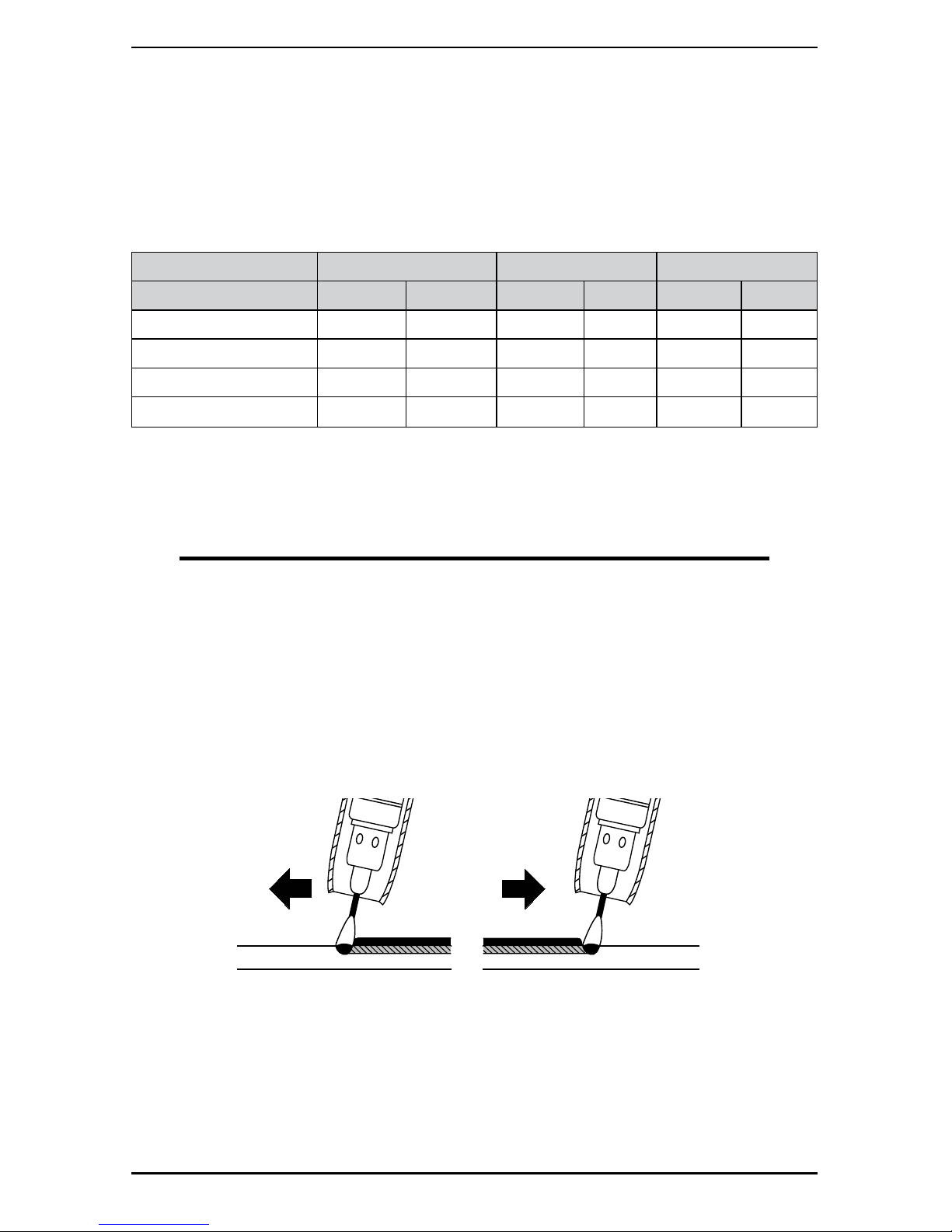
When horizontal welding, hold the torch vertical to the workpiece (neutral torch position) or up to 30°,
“pushing" the torch. For best depth of penetration and shielding gas coverage, hold the torch in the
neutral position. Please note that if the torch is tilted too far, it is possible that air will be sucked into
the shielded gas and may result in porosity. For vertical or overhead welding, a slight pushing motion
is required. For vertical-down welding, mostly used for thin materials, hold the torch at the neutral
or slightly “dragging" position. Some experience is required since the welding pool could run ahead
of the arc and cause weld defects. Thicker material presents a danger of possible lacks of fusion
because the welding pool is very liquid from high voltage and quick travel speed.
Welding direction
pushing the weld
Welding direction
dragging the weld
Avoid extreme side-to-side movements to avoid the weld pool damming up in front of the arc. If the
welding pool flows ahead of the welding arc, lacks of fusion might occur. Use a side-to-side motion at
a necessary width to reach both sides of the joint. If the joint is too wide, weld two parallel weld beads.
When performing vertical-up welding, the side-to-side motion follows the shape of an open triangle.
Manual GMAW Welding
Page 23

safety and operating instructions
6-1989200008
A. Length of the arc
Welding with a longer arc reduces the penetration and the welding bead is wide and flat with increased
spattering. The welding material is transferred with slightly larger drops than welding with a shorter
arc. A longer arc is useful for welding a fillet weld to form a flat or concave seam. Welding with a
shorter arc (at the same amperage) increases the penetration, and the welding bead is narrow and
high with reduced spattering. The welding material is transferred with smaller droplets.
Long Arc Short Arc
B. Length of the wire electrode
The distance between the torch and the workpiece should be 10-12 times the diameter of the wire.
Altering the distance of the torch will influence the electrode stick out.
A longer electrode stick out reduces the amperage and the penetration.
A shorter electrode stick out increases the amperage if the wire feed speed remains the same.
Long electrode stick out
Short electrode stick out
Manual GMAW Welding
Page 24

7-20
safety and operating instructions
89200008
SECTION 7:
CONTACT TIP
7.01 CONTACT TIP IDENTIFICATION AND PARTS LIST
The procedure for removal and installation of a wire contact tip is similar for all Tweco® MIG
Guns. Contact tips may be identified by markings on the side of the tip.
Standard Contact Tips
Part Number Stock No.
Tip ID
in(mm)
Wire Size
in(mm)
16PS-30 1160-1543 0.038 (0,9) .030 (0,8)
16PS-35 1160-1535 0.044 (1,1) .035 (0,9)
16PS-40 1160-1536 0.048 (1,22) .040 (1,0)
16PS-45 1160-1537 0.054 (1,4) .045 (1,2)
16APS-364 1160-1538 0.063 (1,6) .047 (1,9)
16PS-52 1160-1541 0.058 (1,5) .052 (1,3)
16PS-116 1160-1539 0.073 (1,8)
.062 (1,6)
16APS-116 1160-1540 0.082 (2,1)
7.02 CONTACT TIP REPLACEMENT
NOTE
Replace contact tip if hole is enlarged or deformed.
1. Select the correct contact tip according to the wire used.
2. Remove the nozzle from the gun to reveal the contact tip.
3. Remove the contact tip. Replace contact tip and tighten plier tight.
Contact Tip
Page 25

safety and operating instructions
8-2189200008
SECTION 8:
WIRE CONDUIT
8.01 CONDUIT IDENTIFICATION AND PARTS LIST
The procedure for removal and installation of a wire conduit is similar for all Tweco® MIG guns.
Conduits may be identified by the type of conduit stop and the part number marking on each
conduit stop.
Example Part Number: Abbreviation / Definition
PMP44-116-33
PullMaster
44 Series
1/16" (1,6mm) Wire Capacity
Liner length in feet
P PullMaster
TF Teflon® Construction
WN Wire / Nylon
J Jumper
Aluminum / Stainless Steel Series Wire Conduits
Part No. Stock No. Wire Size Length
PMP44-116-33
1441-1125
3/64" (1,2mm) - 1/16" (1,6mm) Aluminum
33' (10M)
PMP44-116-50 1441-1126 50' (15M)
PMP44-3545-33 1441-1127
.035 (0,9mm) - .045" (1,1mm) Aluminum
33' (10M)
PMP44-3545-50 1441-1128 50' (15M)
PMPS44-116-33 1411-1129
3/64" (1,2mm) - 1/16" (1,6mm) Steel Wire
33' (10M)
PMPS44-116-50 1441-1130 50' (15M)
PMPS44-3545-33 1441-1131
.035" (0,9mm) - .045" (1,1mm) Steel Wire
33' (10M)
PMPS44-3545-50 1441-1132 50' (15M)
PMP-44FLX-116 1644-1095 Teflon Jump Liner for Flex Tubes
N/APMP-44PTF-116 1644-1096 Teflon Jump Liner for Rigid Tubes
PMP-44-116 1644-1097 Bronze Jump Liner for Steel Wire And Rigid Tubes
8.02 CONDUIT REMOVAL
NOTE
Replace liner if it is kinked, or if the hole is dirty, or worn. Make sure the end of the
liner is smooth.
1. Lay the gun out on a table or on the floor in a straight line. Make sure the gun is fully
extended and all twists in the cable are removed.
2. Loosen the conduit set screw in the gas diffuser.Then loosen the conduit set screw in
the rear connector plug.
NOTE
On Euro-Kwik® connections, remove the conduit retaining cap.
3. Grip the conduit stop and remove the conduit with a clockwise twisting motion and pull
from assembly.
Wire Conduit
Page 26

8-22
safety and operating instructions
89200008
CONDUCTOR TUBE
CONDUIT LINER
REMOVE
CONSUMABLES
CONDUIT LINER
CONDUIT
SET SCREW
O-RINGS
CONNECTOR PLUG
CONDUIT SET SCREW
Figure 2: Pull Gun - Change Conduit
8.03 CONDUIT INSTALLATION
NOTE
Fully extend the Pull Gun out in a straight line, removing all twists before proceeding.
When installing a standard liner with the brass conduit cap, the following steps are recommended
to install pieces into the gun:
1. Loosen the set screw in the front block and rear power plug, then remove the old liner
from the gun.
2. Lay the old liner out straight beside the new one. Cut new one to length.
3. Gently feed the new liner into the gun with short strokes without kinking. Ensure that
there are no burrs or sharp ends on the conduit.
NOTE
If the conduit is held too far away from the rear plug, the conduit may kink
when inserting. Kinks will cause poor feed.
3" - 4"
(7cm-10cm)
8" - 10"
(20cm-25cm)
a. Correct Liner Feed Method:
Use short strokes
b. Incorrect Liner Feed Method:
Handling liner too far from plug
Wire Conduit
Page 27
safety and operating instructions
8-2389200008
NOTE
If the liner gets caught inside the gun, twist in a clockwise direction while
gently pushing.
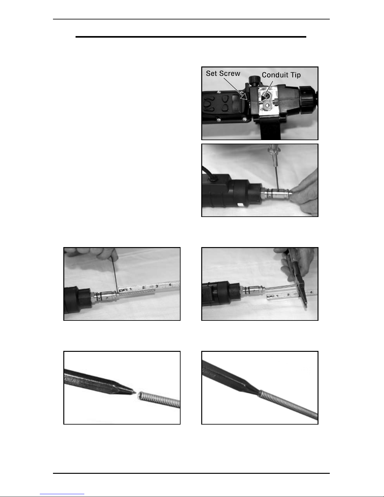
4. Feed the end of the liner through the plug
until the conduit tip reaches the front
block guide hole and secure with the front
block set screw.
5. Secure the back end of the liner by
pushing the conduit stop into the rear
feeder power plug.
6. Tighten set screw in plug with hex key then trim conduit stick out to 2-7/16"
+.000 / -1/16" (61,9mm +0 / -1,6mm)
7. After trimming conduit, use a pointed punch to ensure that the nylon inside conduit is
open and not squeezed shut.
Wire Conduit
Page 28

8-24
safety and operating instructions
89200008
8.04 JUMP LINER INSTALLATION
When installing a jump liner, the following steps are recommended to install pieces into the tube:
1. Remove the conductor tube by loosening the conductor screw cap, then loosen gas
diffuser set screw.
2. Remove jump liner from conductor tube.
3. Make sure that both new and old jump
liners are the same length. Feed the end of
the new jump liner into the conductor tube
until it stops. Secure with diffuser set screw.
If unsure if the liner is seated properly in
the diffuser, remove the set screw and liner
should be visible inside the set screw hole.
NOTE
Do not overtighten the set screw
on the jump liner or the bronze
material will collapse under
extreme pressure. The jump liner
should extend 3/16" (4,7mm) past
the rear flat on the conductor tube.
4. Install conductor tube on the front of the
handle and twist locking nut clockwise to
secure. Insure that the liner in the tube is
seated in the front guide on gun before
tightening.
Wire Conduit
Page 29

safety and operating instructions
8-2589200008
8.05 LINER GUIDE ASSEMBLY REPLACEMENT
1. Remove conductor tube and proceed with removing the conduit liner guide assembly
with a 3/8" wrench and flat screwdriver.
2. Replace liner into guide.
3. Screw liner guide into gun and attach nut.
Do not overtighten nut.
4. Install new assembly into block using
pliers or a 3/8" open end wrench and
screwdriver.
5. If using the white Teflon liner in the front
steel liner guide, the liner should be
1 3/4" (44,5mm) long and protrude out
the rear of the guide (threaded end) 1/8"3/16" (3,2mm - 4,8mm).
6. The plated steel or copper liner guide
that anchors the conduit between the
gun drive roll and conductor tube should
protrude no more than 1/8" (3,2mm) from
the gun body after assembly.
NOTE
Make sure the white liner is not
forced back against the gun
drive roll.
Wire Conduit
Page 30

9-26
safety and operating instructions
89200008
SECTION 9:
CONDUCTOR TUBES
CONDUCTOR TUBES
Part No. Stock No. Description
PMP64EL-180 1642-1140 180° Rigid Conductor Tube (Standard)
PMP64EL-30 1642-1141 30° Rigid Conductor Tube
PMP64SFLX-360 1642-1142 Knucklehead™ Flexible Conductor Tube
SECTION 10:
NOZZLES
AIR-COOLED
Part No. Stock No.
Nozzle ID
in (mm)
OD
in (mm)
Tip Relationship
PMA24-50F 1260-1710
1/2 (12,5)
0.875 (22,5)
Flush
PMA24-50 1260-1711 Recessed 0.156" (4,0 mm)
PMA24-62F 1260-1712
5/8 (15,9)
Flush
PMA24-62 1260-1713 Recessed 0.156" (4,0 mm)
PMA24H-62 1260-1720 0.870 (22,1) Recessed 0.156" (4,0 mm)
PMA24-75F 1260-1714
3/4 (19,1)
0.875 (22,5)
Flush
PMA24-75 1260-1715 Recessed 0.156" (4,0 mm)
PMA24H-75 1260-1721 0.970 (24,6) Recessed 0.156" (4,0 mm)
Conductor Tubes / Nozzles
Page 31

safety and operating instructions
11-2789200008
SECTION 11:
REPLACING PCB ASSEMBLY (SMART GUN)
WARNING
Turn off power supply and disconnect MIG gun BEFORE performing any
maintenance.
1. Remove two screws on each side of
the PCB cover panel using a Phillips
screwdriver.
2. Remove PCB housing to expose the PCB assembly.
a. Remove housing b. PCB
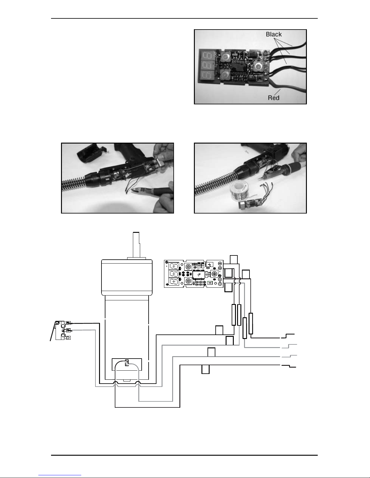
3. Cut the lead wires coming from the PCB
as close to the board as possible.
NOTE
The leads on the PCB assembly are color coded. Use the "Smart Gun PCB Assembly
Diagram" to identify proper connections.
Replacing PCB Assembly (Smart Gun)
Page 32
11-28
safety and operating instructions
89200008
4. Remove approximately a 1/4" (6,4mm) of
the insulator jacket on each of the four
control lead wires protruding from the
cable of the MIG Gun.
5. Solder control lead wires from cable hose to proper control leads of PCB (as specified
on the schematic below, "Smart Gun PCB Assembly Diagram").
BLACK (+)
RED (-)
WHITE
WHITE
NO
NC
GREEN
WHITE
GREEN
GREEN
PINK
BLACK
BLACK
BLACK
BLACK
RED
HEAT
SHRINK
1
A
C
2
B
D
4
3
Smart Gun PCB Assembly Diagram
Replacing PCB Assembly (Smart Gun)
Page 33

safety and operating instructions
12-2989200008
SECTION 12:
TROUBLESHOOTING
Contact tips and nozzles should be cleaned frequently. Spatter buildup may cause bridging
between nozzle and tip. This could cause electrical shorting between the nozzle and work
piece as well as poor or improper gas flow. Regularly inspect the conductor tube, handle,
cable, and other parts of the MIG gun for abrasion, cuts, or undue wear. Replace or repair any
parts found deficient.
Problem Possible Cause Corrective Action
Wire feed inconsistent, not
smooth, or is bird nesting.
1. Loose contact tip or diffuser. 1. Tighten contact tip and diffuser
plier tight.
2. Excessively worn contact tip. 2. Replace contact tip.
3. Spatter buildup on end of
contact tip.
3. Clean or replace contact tip.
4. Sharp bends or kinks in conduit. 4. Straighten or replace conduit.
5. Dirty or plugged conduit. 5. Replace conduit.
6. Conduit pulled back from
diffuser.
6. Reposition conduit and tighten
front set screw.
7. Machine improperly adjusted. 7. Reset machine per machine
and wire manufacturers’
recommendations.
8. Gap between drive rolls and
outlet guide inside feeder.
8. Move outlet guide right up to drive
rolls without touching and tighten
the guide nut
MIG gun is running hot
1. Loose contact tip or diffuser. 1. Tighten contact tip and diffuser
plier tight.
2. Loose power connections. 2. Inspect complete gun for loose
connections and repair.
3. Loose or undersized ground
cable or ground clamp.
3. Tighten or replace as required.
4. Operating gun above
recommended amperage rating.
4. Readjust machine to correct
setting for size of gun being used.
Porosity
1. Poor or improper gas flow.
Possibly due to the outlet
guide nut on feeder not being
tightened down on guide.
1. Check gas flow out of gun nozzle.
Check for leaks or restrictions
in gas hoses and connections.
Check for O-ring damage on rear
connector plug. Check outlet guide
nut on feeder; tighten if not already
done.
2. Dirty or contaminated wire. 2. Change wire.
3. Base metal contaminated. 3. Replace base metal or
brush clean.
Receiving error M12 on SP
machine or calibration is
not working.
1. The machine was not calibrated
after changing the gun or turning
the machine on or off.
1. Calibrate machine (refer to section
4.02).
2. The wire is not completely
through gun.
2. Run wire through the entire length
of gun.
3. The drive rolls on machine or
gun are not closed down on
wire.
3. Close drive rolls on both the
machine and gun and feed wire
through gun.
4. The machine is not set for the
correct push/pull gun.
4. Check settings on machine, reset
and re-calibrate if needed.
Troubleshooting
Page 34

13-30
safety and operating instructions
89200008
SECTION 13:
REPLACEMENT PARTS
14
4
5
9
3
2
1
15
8
10
6b
13
16
20
6
11
6a
7
12
12
19
18
17
17
Replacement Parts
Page 35

safety and operating instructions
13-3189200008
Item
No.
Part No. Stock No. Description
1 See Section 10 Nozzle
2 See Section 7 Contact Tip
3 PMA54-16S 1543-1106 Diffuser
4 See Section 9 Conductor Tube
5
PMP-44FLX-116 1644-1095 Teflon Jump Liner f/flex tube
PMP-44PTF-116 1644-1096 Teflon Jump Liner f/rigid tubes
PMP-44-116 1644-1097 Bronze Jump Liner for Steel Wires (Rigid Tubes)
6a EPG186 2031-2046 Support Assy Front (STD)
6b PMPS186 2060-2725
Support Assy Front (Including Smart cover, PCB membrane, lens & lower
support)
7
PMP44-116-33 1441-1125 33' Conduit Assy (3/64" - 1/16" / 1,2mm - 1,6mm wire)
PMP44-116-50 1441-1126 50' Conduit Assy (3/64"-1/16" / 1,2mm - 1,6mm wire)
PMP44-3545-33 1441-1127 33' Conduit Assy (.035" - .045" / 0,9mm - 1,1mm wire)
PMP44-3545-50 1441-1128 50' Conduit Assy (.035" - .045" / 0,9mm - 1,1mm wire)
PMPS44-116-33 1441-1129 33' Conduit Assy (3/64" - 1/16" / 1,2mm - 1,6mm Steel wire)
PMPS44-116-50 1441-1130 50' Conduit Assy (3/64" - 1/16" / 1,2mm - 1,6mm Steel wire)
PMPS44-3545-33 1441-1131 33' Conduit Assy (.035" - .045" / 0,9mm - 1,1mm Steel wire)
PMPS44-3545-50 1441-1132 50' Conduit Assy (.035" - .045" / 0,9mm - 1,1mm Steel wire)
8 PMP103 2060-1726 Head Block Assy
NS
SPG103-1 2060-1727 Pressure Arm Assy
SPG103-8 2060-1728 Idler Bearing Assy
9
PMPS-106TA 2060-1729 Front Wire Guide Assy (Aluminum)
PMP-106TA 2060-1730 Front Wire Guide Assy (Steel)
10
EPG103-2-0.8 2031-2091 Drive Roll (.030" / 0,8mm wire)
EPG103-2-0.9 2031-2077 Drive Roll (.035" / 0,9mm wire)
EPG103-2-1.0 2031-2023 Drive Roll (.040" / 1,0mm wire)
EPG103-2-1.2 2031-2003 Drive Roll (3/64" / 1,2mm wire)
EPG103-2-1.6 2031-2022 Drive Roll (1/16" / 1,6mm wire)
EPG103-2-1.6V 2031-2134 Drive Roll V-Groove (1/16" / 1,6mm Steel wire)
EPG103-2-1.2V 2031-2135 Drive Roll V-Groove (3/64" / 1,2mm Steel wire)
EPG103-2-0.9V 2031-2136 Drive Roll V-Groove (.035" / 0,9mm Steel wire)
11 SPG-RWG 2031-2137 Power Cable Connector Assy
NS EPG86-2 2031-2013 Handle Cover Assy
12 PMP-T6RC 2060-2731 Rear Case Assy
13 PMP-M24 2060-2732 Motor Assy (24V)
14 SPG-96TL 2060-2733 Trigger Lever
15 SPG86 2060-2734 Handle Assy
16
PMP300-33 2060-2750 Cablehoz Assembly 33' (10M) Standard
PMP300-50 2060-2751 Cablehoz Assembly 50' (15M) Standard
PMP300X-33 2060-2752 Cablehoz Assembly 33' (10M) Standard (Euro-kwik)
PMP300X-50 2060-2753 Cablehoz Assembly 50' (15M) Standard (Euro-kwik)
17 PMP-X6RC 2060-2736 Rear Case Assy (Euro-kwik)
18 174X-2 2040-2177 Euro-Kwik Nut
19 EPG171-1T 2031-2044 Euro Kwik Rear Assy
NS
BG-53N04 8040-1998 Hose Clamp Package Of 5
EPG-HW 2031-2088 Hex Key
PMP-PV 2060-2737 Poppet Valve Assembly
20 PM85-PCB 2060-2738 Replacement PCB
NS
EPG354T 2031-2084 Tweco control wire
EPG354M 2031-2086 Miller control wire
EPG354L 2031-2085 Lincoln control wire
PMP354T 2031-2145 EPG-CR2 Jumper wire
EPG174MH 2040-2164 Miller Connector Plug
EPG174LH 2040-2162 Lincoln Connector Plug
EPGHK1 2031-2090 Gas Hook up Kit
NS = Not Shown
Replacement Parts
Page 36

14-32
safety and operating instructions
89200008
SECTION 14:
STATEMENT OF WARRANTY
LIMITED WARRANTY: THERMADYNE
®
warrants that its products will be free of defects
in workmanship or material. Should any failure to conform to this warranty appear within
the time period applicable to the THERMADYNE products as stated below, THERMADYNE
shall, upon notification thereof and substantiation that the product has been stored,
installed, operated, and maintained in accordance with THERMADYNE’s specifications,
instructions, recommendations and recognized standard industry practice, and not subject
to misuse, repair, neglect, alteration, or accident, correct such defects by suitable repair or
replacement, at THERMADYNE®’s sole option, of any components or parts of the product
determined by THERMADYNE® to be defective.
THIS WARRANTY IS EXCLUSIVE AND IS IN LIEU OF ALL OTHER WARRANTIES,
EXPRESS OR IMPLIED, INCLUDING ANY WARRANTY OF MERCHANTABILITY OR
FITNESS FOR A PARTICULAR PURPOSE.
LIMITATION OF LIABILITY:
THERMADYNE® shall not under any circumstances be
liable for special or consequential damages, such as, but not limited to, damage or loss
of purchased or replacement goods, or claims of customers of distributor (hereinafter the
“Purchaser") for service interruption. The remedies of the Purchaser set forth herein are
exclusive and the liability of THERMADYNE® with respect to any contract, or anything done in
connection therewith such as the performance or breach thereof, or from the manufacture,
sale, delivery, resale, or use of any goods covered by or furnished by THERMADYNE®
whether arising out of contract, negligence, strict tort, or under any warranty, or otherwise,
shall not, except as expressly provided herein, exceed the price of the goods upon which
such liability is based.
THIS WARRANTY BECOMES INVALID IF REPLACEMENT PARTS OR ACCESSORIES
ARE USED WHICH MAY IMPAIR THE SAFETY OR PERFORMANCE OF ANY
THERMADYNE PRODUCT.
THIS WARRANTY IS INVALID IF THE PRODUCT IS SOLD BY NON-AUTHORIZED
PERSONS.
This warranty is effective for the time stated in the Warranty Schedule beginning on the date
that the authorized distributor delivers the products to the Purchaser.
Warranty repairs or replacement claims under this limited warranty must be submitted
by an authorized THERMADYNE® repair facility within thirty (30) days of the repair. No
transportation costs of any kind will be paid under this warranty. Transportation charges
to send products to an authorized warranty repair facility shall be the responsibility of the
Purchaser. All returned goods shall be at the Purchaser’s risk and expense. This warranty
supersedes all previous THERMADYNE® warranties.
Statement of Warranty
Page 37

safety and operating instructions
14-3389200008
14.01 WARRANTY SCHEDULE
The warranty is effective below for the time stated in the Warranty Schedule beginning on
the date that the authorized distributor delivers the products to the purchaser. THERMADYNE
®
reserves the right to request documented evidence of date of purchase.
Engine Driven Welders
Parts / Labor
Scout®, Rraider®, Explorer
™
Original Main Power Stators and Inductors 3 years / 3 years
Original Main Power Rectifiers, Control P.C. Boards 3 years / 3 years
All Other Original Circuits and Components Including, but not Limited to, Relays, Switches,
Contactors, Solenoids, Fans, Power Switch Semi-Conductors
1 year / 1 year
Engines and Associated Components are NOT Warranted by Thermal Arc®, Although
Most are Warranted by the Engine Manufacturer. SEE THE ENGINE MANUFACTURERS’
WARRANTY FOR DETAILS.
See the Engine
Manufacturers’
Warranty for Details
GMAW/FCAW (MIG) Welding Equipment
Parts / Labor
Fabricator® 131, 181, 190, 210, 251, 281; Fabstar® 4030; PowerMaster®
320SP, 350, 350P, 400SP, 500SP, 500, 500P; Excel-Arc® 6045; Wire
Feeders: Ultrafeed®, Porta-feed
®
Original Main Power Transformer and Inductor 5 years / 3 years
Original Main Power Rectifiers, Control P.C. Boards, Power Switch Semi-Conductors 3 years / 3 years
All Other Original Circuits and Components Including, but not Limited to, Relays, Switches,
Contactors, Solenoids, Fans, Electric Motors
1 year / 1 year
GTAW (TIG) & Multi-process Inverter Welding Equipment
Parts / Labor
160TS, 300TS, 400TS, 185AC/DC, 200AC/DC, 300AC/DC, 400GTSW,
400MST, 300MST, 400MSTP
Original Main Power Magnetics 5 years / 3 years
Original Main Power Rectifiers, Control P.C. Boards, Power Switch Semi-Conductors 3 years / 3 years
All Other Original Circuits and Components Including, but not Limited to, Relays, Switches,
Contactors, Solenoids, Fans, Electric Motors
1 year / 1 year
Plasma Welding Equipment
Parts / Labor
Ultima® 150
Original Main Power Magnetics 5 years / 3 years
Original Main Power Rectifiers, Control P.C. Boards, Power Switch Semi-Conductors 3 years / 3 years
Welding Console, Weld Controller, Weld Timer 3 years / 3 years
All Other Original Circuits and Components Including, but not Limited to, Relays, Switches,
Contactors, Solenoids, Fans, Electric Motors, Coolant Recirculators
1 year / 1 year
SMAW (Stick) Welding Equipment
Parts / Labor
Dragster™ 85
Original Main Power Magnetics 1 year / 1 year
Original Main Power Rectifiers, Control P.C. Boards 1 year / 1 year
All Other Original Circuits and Components Including, but not Limited to, Relays, Switches,
Contactors, Solenoids, Fans, Power Switch Semi-Conductors
1 year / 1 year
160S, 300S, 400S Parts / Labor
Original Main Power Magnetics 5 years / 3 years
Original Main Power Rectifiers, Control P.C. Boards 3 years / 3 years
All Other Original Circuits and Components Including, but not Limited to, Relays, Switches,
Contactors, Solenoids, Fans, Power Switch Semi-Conductors
1 year / 1 year
Statement of Warranty
Page 38

14-34
safety and operating instructions
89200008
General Arc Equipment Parts / Labor
Water Recirculators 1 year / 1 year
Plasma Welding Torches 180 days / 180 days
Gas Regulators (Supplied with Power Sources) 180 days / NA
MIG and TIG Torches (Supplied with Power Sources) 90 days / NA
Replacement Repair Parts 90 days / NA
MIG, TIG and Plasma Welding Torch Consumable Items NA / NA
Gas Welding and Cutting Equipment Parts / Labor
Victor® Professional 5 years / NA
Oxygen Conservers 2 years / NA
Aluminum Cylinders Lifetime / NA
Cutting Machine Motors 1 year / NA
HP&I Brass Regulators/Manifolds 2 years / NA
HP&I Stainless Regulators/Manifolds 1 year / NA
HP&I Corrosive Gas Regulators/Manifolds 90 days / NA
TurboTorch
®
3 years / NA
CutSkill
®
2 years / NA
Steel Cylinders 1 year / NA
Victor Medical 6 years / NA
Victor VSP 2 years / NA
Firepower® MIG Welders 5-2-1 years / NA
Transformers 5 years / NA
Parts Used in Rental Applications
1 year from date sold
by seller to authorized
distributor
MIG Torches and Arc Accessories Parts / Labor
Arcair® N6000 90 days / NA
Spool and Pull Guns 90 days / NA
Robotic Deflection Mounts 90 days / NA
QRM-100 Anti-Spatter Applicator 90 days / NA
TC and TCV Water Coolers 1 year / NA
TSC-96 Smoke Collector 1 year / NA
ESG-1, EPG-CR2 Control Boxes for Spool & Pull Guns 1 year / NA
QRC-2000 Nozzle Cleaning Stations 1 year / 1 year
QRC-3000 UltraSonic Cleaning Stations 2 years / 2 years
All other products 30 days from date purchaser purchases from seller. 30 days / NA
Plasma Cutting Systems Parts / Labor
Automated Plasma 2 years / 1 year
CutMaster
™
3 years / 3 years
PakMaster® XL PLUS 3 years / 1 year
Drag-Gun
®
1 year / 1 year
Drag-Gun Plus 2 years / 1 year
Torches 1 year / 1 year
Consoles, Control Equipment, Heat Exchangers and Accessory Equipment 1 year / 1 year
Statement of Warranty
Page 39

safety and operating instructions
14-3589200008
Page 40

© Thermadyne Industries, Inc., 2009 www.thermadyne.com
Printed in U.S.A.
W O R L D H E A D Q U A R T E R S:
16052 Swingley Ridge Road, Suite 300 • St. Louis, Missouri 63017 U.S.A.
A Global Cutting & Welding Market Leader
™
Oakville, Ontario, Canada
Canada Customer Care
Ph: (1) 905-827-4515
Fax: (1) 800-588-1714
International Customer Care
Ph: (1) 905-827-9777
Fax: (1) 905-827-9797
Melbourne, Australia
Australia Customer Care
Ph: 1300-654-674
Fax: 613+ 9474-7391
International
Ph: 613+ 9474-7508
Fax: 613+ 9474-7488
Rawang, Malaysia
Customer Care
Ph: 603+ 6092-2988
Fax: 603+ 6092-1085
Shanghai, China
Sales Office
Ph: 86 21+ 6280-1273
Fax: 86 21+ 3226-0955
Singapore
Sales Office
Ph: 65+ 6832-8066
Fax: 65+ 6763-5812
Denton, TX USA
U.S. Customer Care
Ph: (1) 800-426-1888
Fax: (1) 800-535-0557
Miami, FL USA
Sales Office, Latin America
Ph: (1) 954-727-8371
Fax: (1) 954-727-8376
THE AMERICAS
Chorley, United Kingdom
Customer Care
Ph: (44) 1257-261755
Fax: (44) 1257-224800
Milan, Italy
Customer Care
Ph: (39) 0236546801
Fax: (39) 0236546840
EUROPE
Cikarang, Indonesia
Customer Care
Ph: 62 21+ 8983-0011 / 0012
Fax: 62 21+ 893-6067
Osaka, Japan
Sales Office
Ph: 816-4809-8411
Fax: 816-4809-8412
ASIA/PACIFIC
U.S. Customer Care:
ARCAIR® / STOODY® / THERMAL ARC® / THERMAL DYNAMICS® /
TWECO® / VICTOR
®
............................. 800-426-1888 / FAX 800-535-0557
FIREPOWER
®
....................................... 800-858-4232 / FAX 800-535-0557
TURBOTORCH
®
..................................... 800-238-0282 / FAX 800-535-0557
TDC AUTOMATION................................ 866-279-2628 / FAX 800-535-0557
VICTOR MEDICAL ................................. 800-382-8187 / FAX 800-535-0557
VICTOR SPECIALTY PRODUCTS........... 800-569-0547 / FAX 800-535-0557
Canada Customer Care: 905-827-4515 / FAX 800-588-1714
International Customer Care: 940-381-1212 / FAX 940-483-8178
CIGWELD Customer Care: 1300-654-674 / FAX 613+ 9474-7391
www.thermadyne.com
Form No.: 89200008
 Loading...