

Page 1
Manual 0-2773
RPT Adapter Kit
Catalog # 7-3445
Installation Instructions
General Information
This Replacement T orch Adapter Kit is to be used to connect the Thermal Dynamics Plasma RPT Series Cutting T orc h
to the following equipment:
• Thermal Dynamics Pak Master 50 with Smart Torch
NOTE
Parts Supplied
For Mechanized Systems refer to the
The following parts are included in this kit:
• Signal Pin Connector with Wires and Connectors (1 ea)
• Pilot Adapter Fitting (1 ea)
• Rubber Insulator (1 ea)
• Tie-Wrap (1 ea)
Torch Control Cable Wiring Diagram on the last page of this Manual.
WARNING
Installation
Disconnect primary power to
Install the Adapter Kit per the following procedur e:
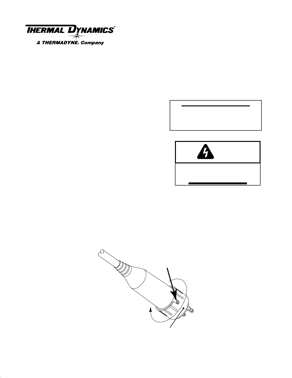
A. Disassembling Old Quick Disconnect
To disassemble the quick disconnect connector, use the following procedure (see Warning):
1. Disconnect the torch leads from the power supply.
2. Turn the outer r etaining nut until one of the three set scr ews in the inner r etaining ring is visible thr ough one
of the slots in the nut.
3. Partially loosen each of the set screws which secure the inner retaining ring and boot onto the quick disconnect body. If the set screws are turned too far out, the outer r etaining nut will not turn properly.
A-00028
Set Screw
(Three)
the system before disassembling
the torch or torch leads.
Rotate outer retaining
nut to access all
three set screws
Outer Retaining Nut
Loosen Set Screws
© 1998 Thermal Dynamics Corp., Printed in USA
Manual 0-2773 1 Installation Instructions 8/21/01
Page 2

4. Pull the protective boot and inner retaining ring from the quick disconnect body.
Protective Boot
Quick Disconnect
Body
Inner Retaining
Ring
Outer Retaining Nut
Rubber Cover &
Tie Wrap
A-00029
Disassembly Of Connector
5. Slide the protective boot and inner retaining ring back over the torch leads to expose the leads connections.
6. Slide the outer retaining nut back over the leads.
7. Using a pair of needle nose pliers remove the two white tabs on each side of the signal connector . These tabs
hold the connector tightly in place to prevent it from moving.
Quick Disconnect
Body
Signal Pin
Connector
A-00164
White Tabs
Removing White Tabs
8. Using a small screwdriver , gently push in the tabs on the front of the Signal Pin Connector. Carefully push the
connector out through the back of the quick disconnect body.
Signal Pin
Connector
Quick Disconnect
Body
A-00030
Removing Signal Pin Connector
9. Cut all the wires connected to the Signal Pin Connector. The rubber boot cannot fit over the Signal Pin Connector.
10. Disconnect the negative/plasma and pilot lead fittings.
Manual 0-2773 2 Installation Instructions 8/21/01
Page 3

Negative/Plasma
Lead Connection
Pilot Lead
Connection
A-00031
Disconnecting Leads
11. Remove the protective boot, inner retaining ring and outer retaining nut from the old leads.
12. Discard the old leads and Signal Pin Connector.
B. Reassembling New Quick Disconnect
1. Slide the protective boot, inner retaining ring and outer
retaining nut from the old torch onto the replacement
torch leads.
Quick Disconnect
Body
Torch Control
Connectors
2. Slide the supplied rubber insulator over the control connector wires on the replacement torch.
Negative/Plasma
3. Install the Pilot Adapter Fitting (left-hand threads) onto
Lead
the pilot fitting of the Quick Disconnect Body and tighten
securely.
Pilot Lead
Adapter
4. Connect the pilot wire (+) from the replacement torch to
the Pilot Adapter Fitting and tighten securely with bolt
and washer provided.
5. Connect the Negative/Plasma Lead from the replace-
A-03009
Pilot Lead
Torch Lead
Assembly
ment torch to the fitting on the Quick Disconnect Body
and tighten securely.
6. Insert the Signal Pin Connector in the quick disconnect
body and install the two white locking tabs on both sides. The bevel must be towards the signal connector.
Quick Disconnect
Body
Signal Pin
Connector
A-00164
White Tabs
Installing The White Locking Tabs
7. On the Signal Pin Connector connect the wires from the two mating connectors on the replacement torch
leads.
8. Slide the rubber insulator down over the control wires and the exposed end of the Signal Pin Connector.
Secure in place with the supplied Tie-Wrap.
9. Slide the outer retaining nut, boot, and inner retaining ring down onto the quick disconnect body.
10. Tighten the thr ee set screws to secure the inner retaining ring onto the quick disconnect body.
Manual 0-2773 3 Installation Instructions 8/21/01
Page 4

1 1. Install the proper torch consumables for the Power Supply amperage.
12. Connect the torch to the Power Supply.
13. Reconnect main input power to the Power Supply and turn the unit ON.
14. Set air pressure to 60 - 70 psi (4.1 - 4.8 bar).
15. Test torch for proper operation.
Torch Control Cable Wiring Diagram For Mechanized Systems
To Torch
Control Device
Control Connector
Wiring & Plugs With
Signal Pin Connector
Part of
Quick Disconnect
A-02571
Torch Control
Connectors
Torch Lead Assembly
Torch Control
Cable
NOTE
Every effort has been made to provide complete and accurate information in this manual. However, the
publisher does not assume and hereby disclaims any liability to any party for any loss or damage caused
by errors or omissions in this manual, whether such errors result from negligence, accident or any other
cause.
Manual 0-2773 4 Installation Instructions 8/21/01
 Loading...