

TVLogic TVC-FG301E User Manual
TVC-FG301E
Full HD Motion Video Camera
User Manual
Ver 1.00

2
User Manual
Contents
Caution ................................................................................................................................ 4
Introduction .............................................................................................................................. 6
Features ......................................................................................................................................................................................... 6
Products & Accessories ............................................................................................................................................................ 8
Ceiling Mount Bracket(ZCB-100) Installation ............................................................................................................... 9
Wall Mount Bracket(ZWB-200)Installation ..................................................................................................................... 10
Installation ............................................................................................................................. 11
① Camera Category-CLASS Setup ..................................................................................................................................... 12
② Camera Address-ADRESS Setup .................................................................................................................................... 13
③ Communication Protocol-PROTOCOL Setup ............................................................................................................ 14
④ Output Video Format-SYSTEM SELECT Setup ......................................................................................................... 14
⑤ Communication Type-COMMUNICATION Setup .................................................................................................... 15
⑥ Connection ............................................................................................................................................................................ 16
⑦ Installation Check ................................................................................................................................................................ 20
⑧ Power ....................................................................................................................................................................................... 21
Main Features .......................................................................................................................... 22
Screen Menu .............................................................................................................................................................................. 22
PRESET .......................................................................................................................................................................................... 23
SWING ........................................................................................................................................................................................... 24
PATTERN ....................................................................................................................................................................................... 24
GROUP .......................................................................................................................................................................................... 25
Other Functions ......................................................................................................................................................................... 25
Menu Function ......................................................................................................................... 26
OSD(On Screen Display) Configuration ........................................................................................................................... 26
Main Menu .................................................................................................................................................................................. 27
➊ Focus/Zoom ....................................................................................................................................................................... 27
➋ White Balance ................................................................................................................................................................... 28
➌ Auto Exposure .................................................................................................................................................................. 28
➍ Picture .................................................................................................................................................................................. 29
➎ Image ................................................................................................................................................................................... 30
➏ Motion/Action .................................................................................................................................................................. 30

Full HD Motion Video Camera
3
Motion ............................................................................................................................................................................... 31
PT Speed Setup .............................................................................................................................................................. 31
Home Position Setup ................................................................................................................................................... 32
North Direction Setup ................................................................................................................................................. 32
Preset Setting .................................................................................................................................................................. 33
Edit Scene- Preset Setup............................................................................................................................................. 33
Edit Label-Preset Setup ............................................................................................................................................... 33
Swing Setup .................................................................................................................................................................... 34
Pattern Setup .................................................................................................................................................................. 34
Group Setup .................................................................................................................................................................... 35
Edit Group-Group Setup ............................................................................................................................................ 36
Parking Action Setup ................................................................................................................................................... 37
➐ Display Setup ..................................................................................................................................................................... 37
Area Label Setup ........................................................................................................................................................... 38
Edit Scene ......................................................................................................................................................................... 39
Edit Label .......................................................................................................................................................................... 40
Area Label Setup ........................................................................................................................................................... 40
➑ System Info. ....................................................................................................................................................................... 41
Additional Info. .............................................................................................................................................................. 42
System Initialize .............................................................................................................................................................. 42
IR Remote Control ................................................................................................................... 43
Controller ................................................................................................................................. 46
Problem Solving ....................................................................................................................... 47
Menu Structure ........................................................................................................................ 48
Default Value .......................................................................................................................... 51
Specifications .......................................................................................................................... 53
Dimension .................................................................................................................................................................................... 55
Glossary ................................................................................................................................... 58
Index ....................................................................................................................................... 60
4
User Manual
Caution
Caution
Don’t open. There may be electric shock.
<Caution>
To avoid the risk of electric shock, do not arbitrarily open the cover or disassemble the
product. There are no user serviceable replacement parts.
Get service from qualified service personnel.
This lightning flash with arrowhead symbol is intended to alert the user to the presence
of un-insulated "dangerous voltage" within the product's enclosure that may be of
sufficient magnitude to constitute a risk of electric shock to person.
This exclamation point symbol is intended to alert the user to the presence of important
operating and maintenance(servicing) instructions in the literature accompanying the
appliance.
This symbol indicates to the user that this is important for operation or
maintenance of the product.
<Caution>

Full HD Motion Video Camera
5
Safety Precautions
Read all of the safety and operating instructions before using the product.
Save these instructions for future reference.
Do not use attachments or accessories unless recommended by the appliance manufacturer as they
may cause hazards, damage product and void warranty.
Do not use this product near water or moisture.
Do not place or mount this product in or on an unstable or improperly supported location.
Improperly installed product may fall, causing serious injury to a child or adult, and damage to the
product. Use only with a mounting device recommended by the manufacturer, or sold with the
product. To insure proper mounting, follow the manufacturer's instructions and use only mounting
accessories recommended by manufacturer.
This product should be operated only from the type of power source indicated on the marking label.
Precautions
Before using, make sure power supply and others are properly connected.
While operating, if any abnormal condition or malfunction is observed, stop using the camera
immediately and then contact your local dealer.
Do not disassemble or tamper with parts inside the camera.
Do not drop or subject the camera to shock and vibration as this can damage camera.
Care must be taken when you clean the clear dome cover. Especially, scratch and dust will ruin your
quality of camera.
Do not install the camera in areas of extreme temperature, which exceed the allowable range.
Avoid installing in humid or dusty places.
Never expose the camera to rain and water.
Avoid installation in a place with radioactivity. It may cause a malfunction of the part.
Avoid installation in locations with strong magnetic fields or electrical signals.
Avoid installing in places where the camera would be subject to strong vibrations.
Precautions for Laser Beam
Laser beam can damage CMOS. When shooting a scene where laser beam is involved, do not let
the beam contacts the CMOS directly.

6
User Manual
Simultaneous Output Video Interface
Introduction
Features
1/2.8inch, 2.38 mega pixels “Exmor” CMOS Sensor Sony Zoom Module Installed.
Supports Max. x360
Various format of HD video output is available and Max. 1920x1080p60 is supported.
1080p
60/59.94/50/30/25
1080i
60/59.94/50
720p
60/59.94/50/30/25
Camera control can be checked by the Tally Led.
Supports the GENLOCK (Tri-Level Sync) function to match video signals of multiple cameras.
Supports the Stereo Audio.
Various output is available such as 3G-SDI, HDMI and for multi-monitoring, simultaneous output is
supported. For MRC series, CVBS is supported.
Optical x30 Zoom Lens
Full HD Output Format
Tally LED
GENLOCK
Audio

Full HD Motion Video Camera
7
Select multiple protocols and communication types
Infrared Cut Filter (IR CUT-Filter) applied
Various Presets & Auto Pan/ Tilt Function
OSD(On Screen Display) Menu Suuport
Smart Flip Function
Powerful Pan/ Tilt Function
Pan: -0˚~ 360˚(Endless), Tilt: total 220˚(-20˚~ 0˚~ 180˚~ -160˚)
This function extend the shooting range by setting the camera to flip the image automatically when it
tilts over 90°.
→ When Smart Flip function is enabled, F letter will be shown in the display.
In order to improve the sensitivity by keeping the light absorption time longer at low light level such as
at night, Slow shutter function and Day & Night switching function are provided so that users can select
color change according to illumination.
Max. 255 assignable presets are supported to save various settings. Also, the CCTV functions like Swing,
Pattern, and Group functions are available for novice users to make stable pan / tilt operation through
preset values.
Enables you to edit detailed settings using the OSD menu.
※ Refer to Page 48 “Menu Structure” to check the menu tree.
VISCA
RS232,RS422
PELCO-D/P
RS485
8
User Manual
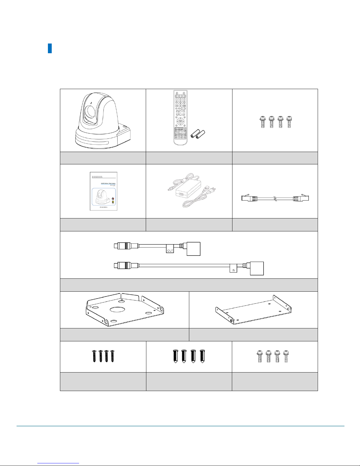
Products & Accessories
Basic Components
Camera
IR remote (with battery)
Camera Bracket Screw
User Manual
AC Adapter
1m RJ45 Cable(Direct)
232C to UTP Cable
Camera Bracket
Ceiling Bracket
Ceiling Bracket Screw
Plastic Anchor
Camera body/ Ceiling
Bracket Screw
Full HD Motion Video Camera
9
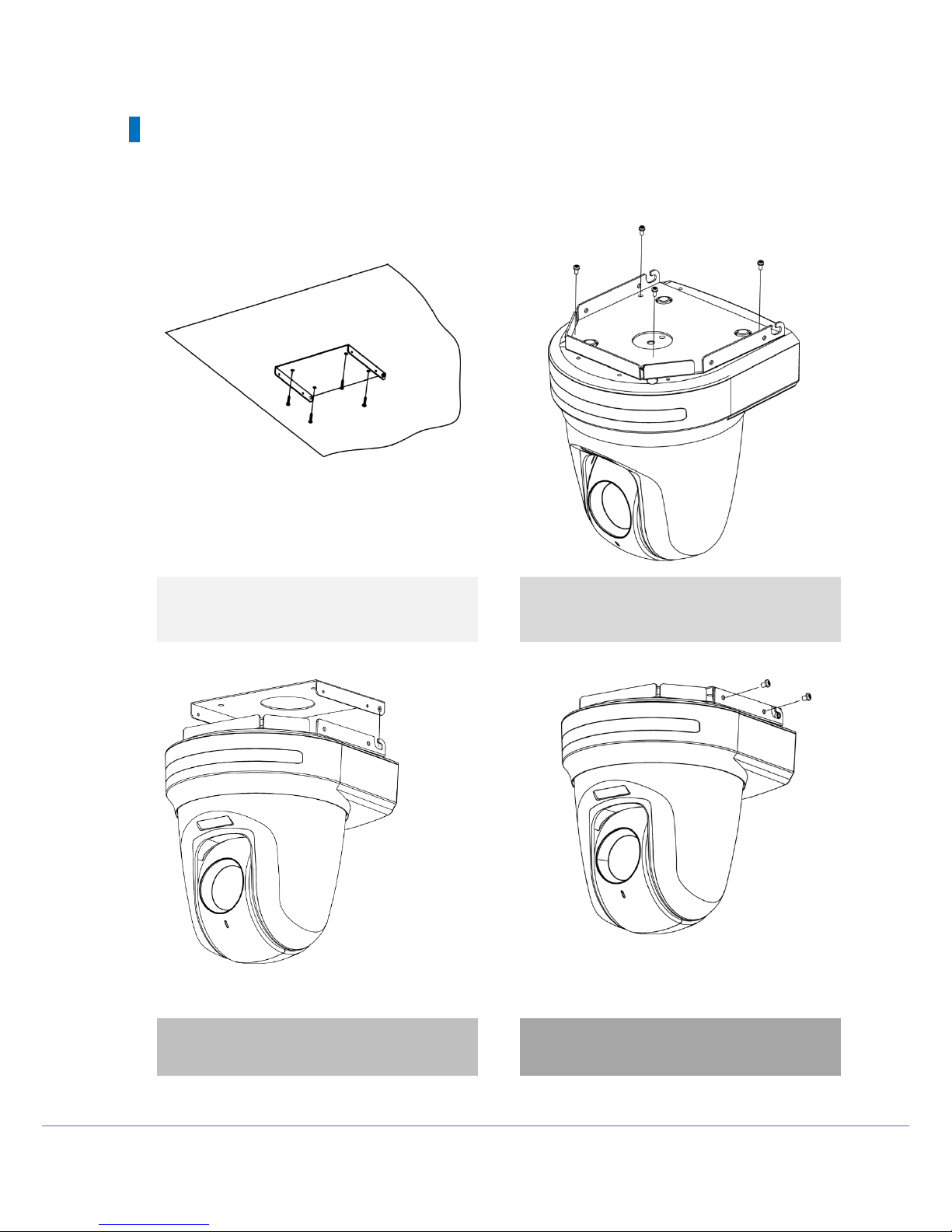
Ceiling Mount Bracket(ZCB-100) Installation
Ceiling bracket installation method
1) Fix the ceiling bracket on the ceiling using the
screws (4EA).
2) Attach the bracket to the camera body as shown
in the picture using the camera bracket and screws
(4EA).
3) Insert the camera bracket into the ceiling
bracket's groove as shown in the picture.
4) Tighten the screws (4EA) on all four sides to fix
the camera.
10
User Manual
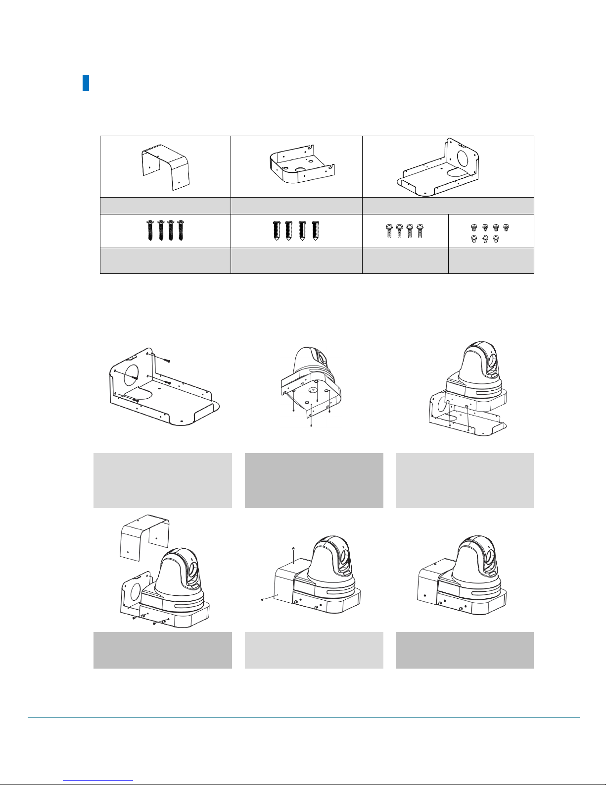
Wall Mount Bracket(ZWB-200)Installation
ZWB-200 Components(Optional)
Installation Method
1) Fix the Wall bracket on the wall
using the wall bracket screws
(4EA).
2) Attach the bracket to the
camera body as shown in the
picture using the camera bracket
and screws (4EA).
3) Insert the camera bracket into
the wall bracket's groove as
shown in the picture.
4) Fix the camera bracket with
screws (4EA)
5) Attach the cover with screws
(3EA).
6) Installation complete
Cover
Camera bracket
Wall bracket
Wall bracket screws
Plastic anchor(For fastening
wall screws)
Camera screws
Bracket screws
Full HD Motion Video Camera
11
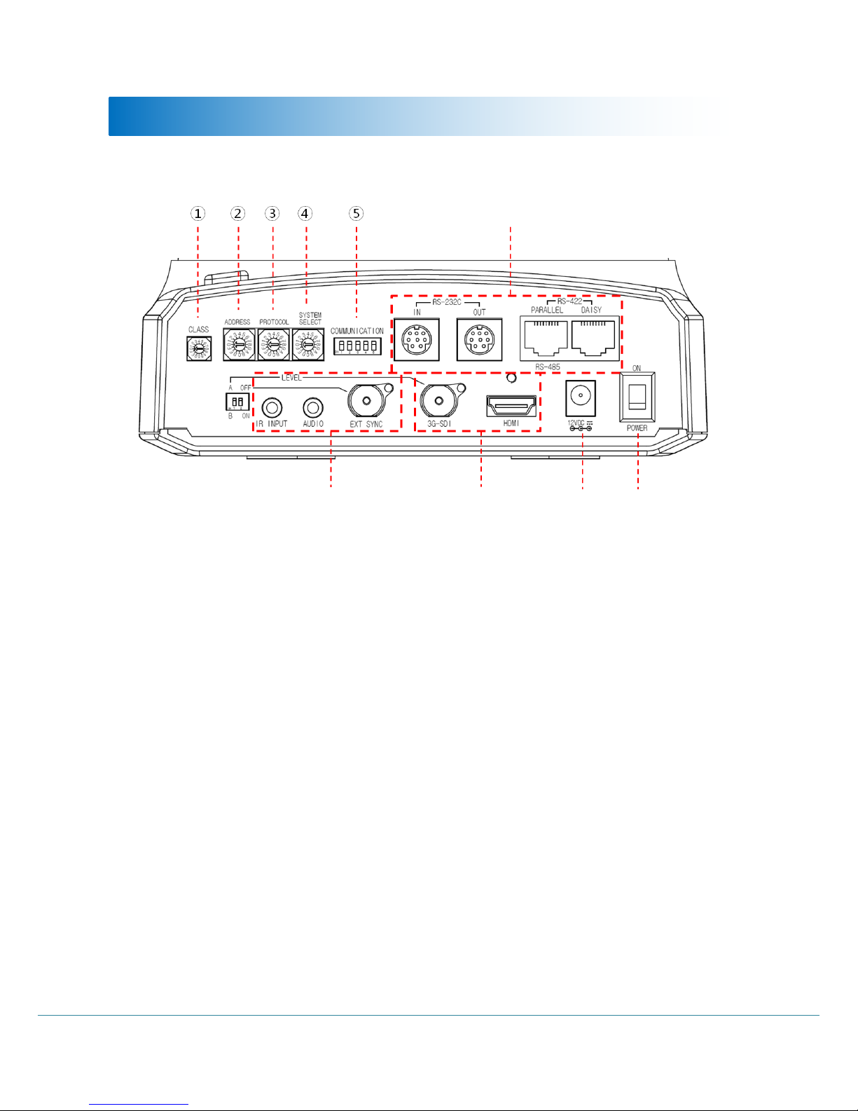
Installation
Communication Type
Input Port
Output Port
Power
Power
Switch
12
User Manual
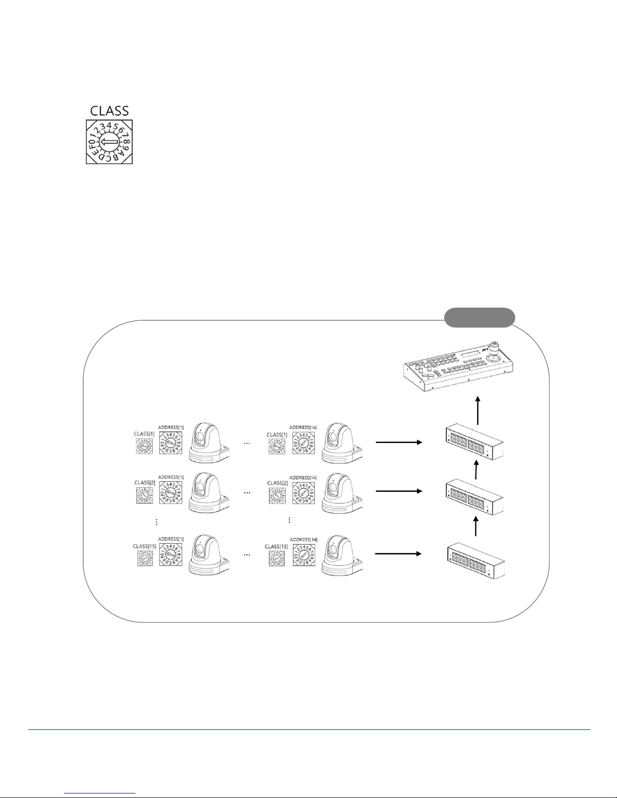
① Camera Category-CLASS Setup
Used to set total 210 camera IDs, 14 Camera address for each CLASS using the CLASS of
the camera.
- Max. 15 CLASSes can be set to control multiple same camera IDs.
※ Number 0 is the same with CLASS OFF.
- Factory default CLASS is OFF (Number 0).
* The CLASS function is available only on the RM-KA200 controller. It is recommended to use optional 422
Hubhub(KTM-200Y).
Sample
Full HD Motion Video Camera
13
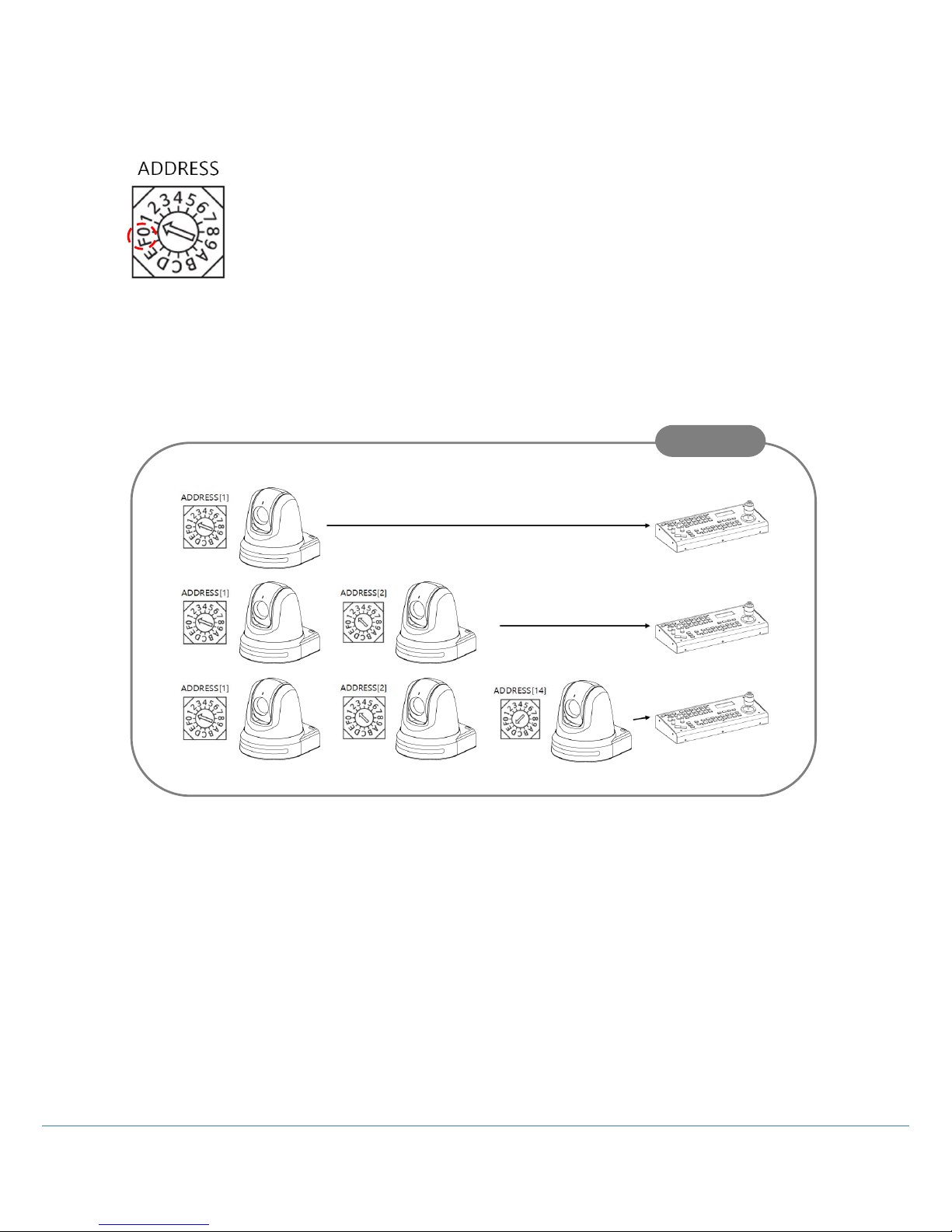
② Camera Address-ADRESS Setup
Change the Camera ID as shown below.
- Up to 14 addresses can be set to control multiple cameras.
※ Do not use Number 0 and 15(F).
- Factory default is set to 1.
When operating multiple cameras with the controller, set the different ID for each
camera.
* It is recommended to use a micro driver to make changes.
Sample
14
User Manual
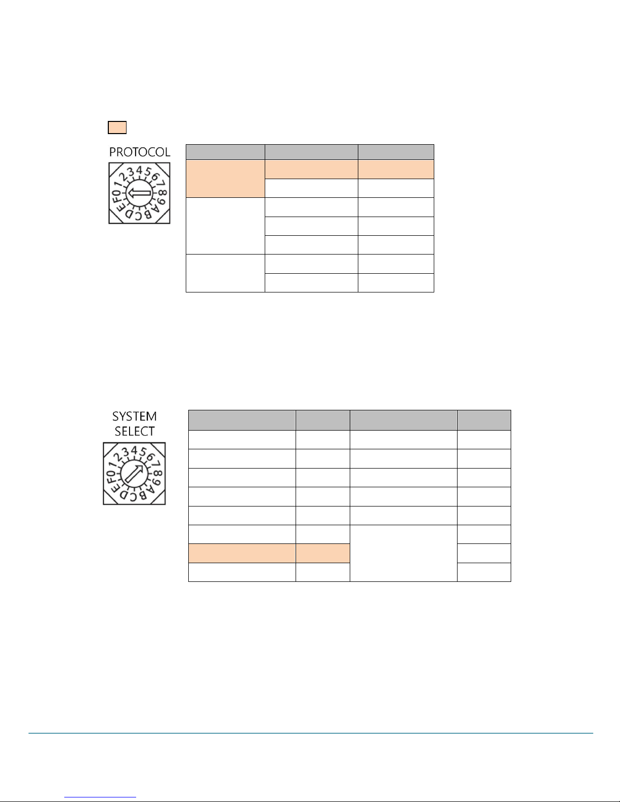
③ Communication Protocol-PROTOCOL Setup
Change the communication protocol as shown below.
: Factory Default
Set the protocol correspond to the controller.
Be sure to change the protocol while the power is off.
④ Output Video Format-SYSTEM SELECT Setup
Set the video output format by changing the switch as shown below.
Make sure to change the format while the power is off.
- HDMI and HD/3G-SDI simultaneous output.
Protocol
BAUDRATE
Switch
VISCA
9600 bps
0
38400 bps
1
PELCO-D
2400 bps
2
9600 bps
3
38400 bps
4
PELCO-P
4800 bps
5
9600 bps
6
Output Video Format
Switch
Output Video Format
Switch
1920x1080p60
0
1920x1080p50
8
1920x1080i60
1
1920x1080i50
9
1920x1080p30
2
1920x 1080p25
A
1280x720p60
3
1280x720p50
B
1280x720p30
4
1280x 720p25
C
1920x1080p59.94
5
Reserved
D
1920x1080i59.94
6 E 1280x720p59.94
7
F
Full HD Motion Video Camera
15
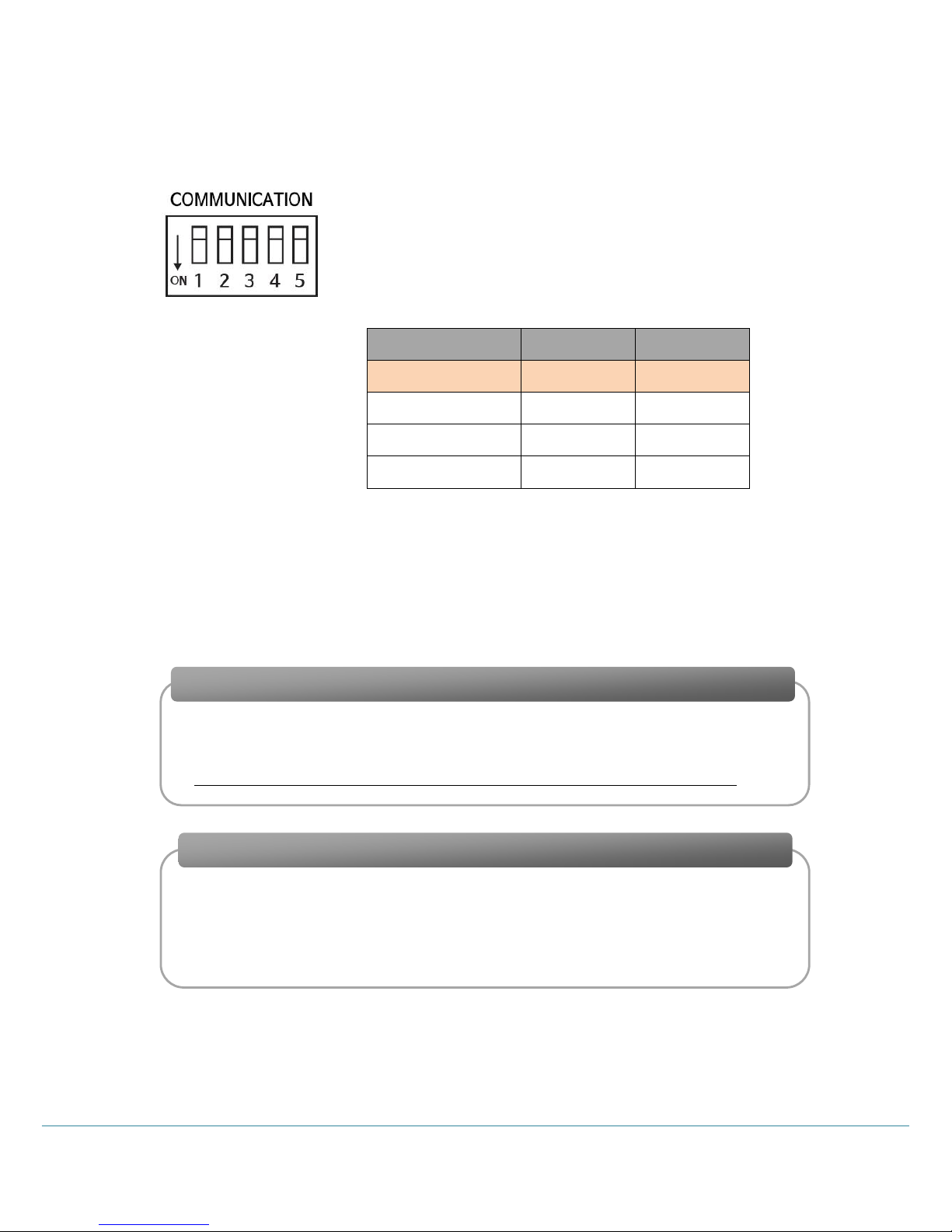
⑤ Communication Type-COMMUNICATION Setup
(OFF: Up / ON: Down)
Set the RS-422 or RS-485 by turning on and off the DIP Swich No.1.
Set the Parallel and Daisy of the RS-422 by turning on and off the DIP
Swich No.2.
The RS-232C communication is available without setting the DIP Switch
separately.
Set the terminating resistance by selecting DIP switches 4 (Rx) and 5 (Tx) as ON / OFF as follows.
* Do not mix the 232C / RS-422 (Parallel) / RS-422 (Daisy) communication methods. There may be a
problem with the operation of the product.
● When using RS-485, terminating resistance is used in the following cases.
* The default setting of terminating resistance is OFF. (Set terminating resistance when
communication error occurs.)
COMMUNICATION
1
2
RS-422(Parallel)
OFF
OFF
RS-422(Daisy)
OFF
ON
RS-485
ON - RS-232C
-
-
If the distance between the controller and the camera is very long, communication
problems may occur due to the impedance problem of the communication line.
In this case, set the terminating resistance to ON for both controller and camera.
Very long communication connection between controller and camera(1: 1 connection)
If you connect multiple cameras simultaneously to one controller, communication
failure may occur. In this case, set the terminating resistance of the controller to ON,
and set the terminating resistance of only one camera on the end to ON.
※ Never set the terminating resistance of all cameras to ON.
When multiple cameras are connected at the same time (1: N connection)
16
User Manual
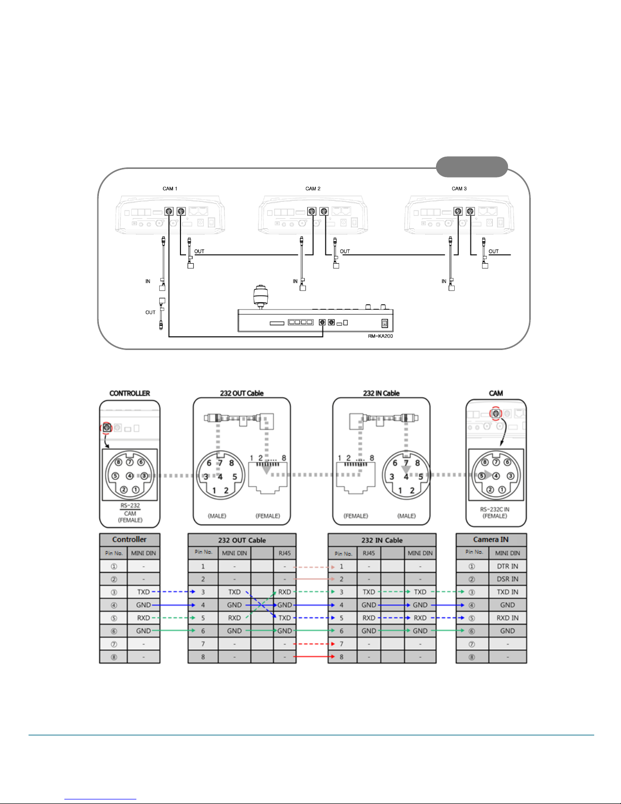
⑥ Connection
Connect a controller that transmits and receives PTZ control commands.
● RS-232C Connection(Mini DIN 8Pin Connector, RJ45 Connector)
1. Connection of Controller and Camera
* Connect the 232 IN / 232 OUT cable using the direct LAN cable.
Sample

Full HD Motion Video Camera
17
2. Multiple Camera Connection
* Connect the 232 IN / 232 OUT cable using the direct LAN cable.
18
User Manual
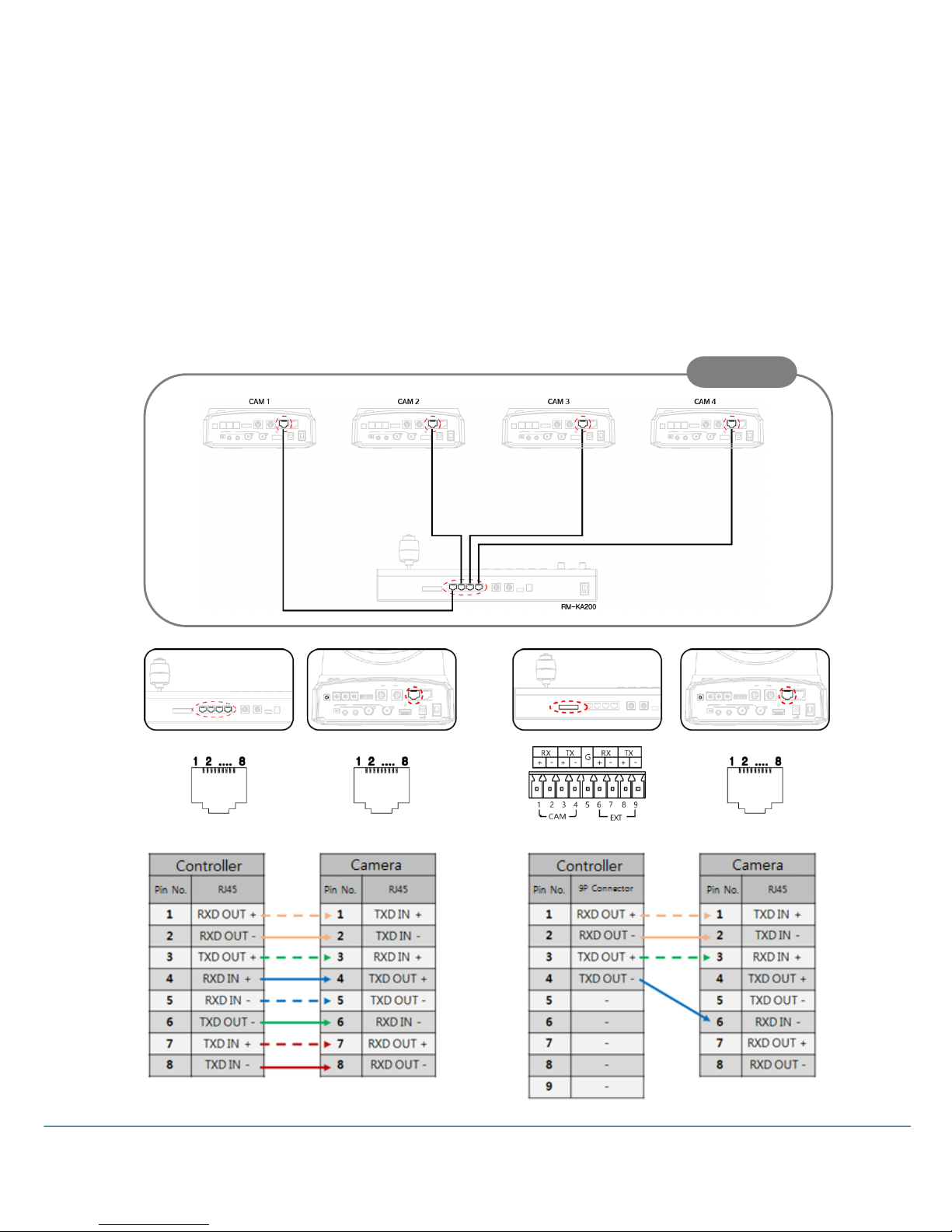
● RS-422 Connection
1. PARALLEL Connection
Used when the cameras connected to the controller are all KE series or PRC /MRC series. In the case of
the PARALLEL connection, when multiple cameras are connected, all the cameras operate normally even
if some cameras don’t have power.
● Connection with the RM-KA200 Controller
<1~4 x Cameras connection >
Sample
Full HD Motion Video Camera
19
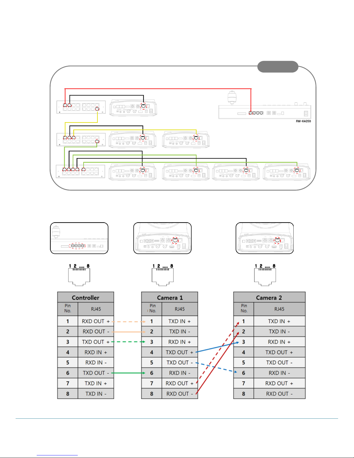
< When connecting more than 4 Cameras >
When using the KTM-200Y
카메라 연속 연결 시 Multiple camera connection
Sample
 Loading...