

TVLogic TVC-FA301N Installation Manual
7
TVC-FA301N
Installation Manual
Ver 1.15
2
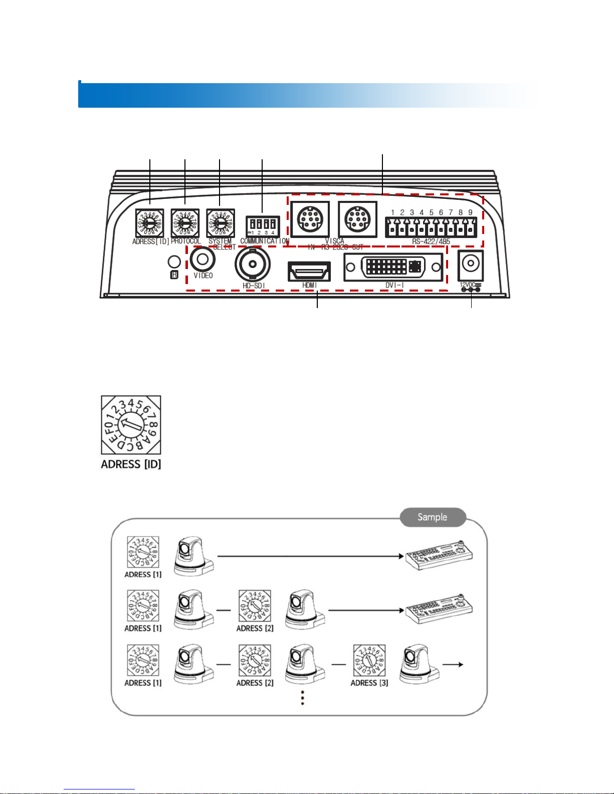
Camera Setup
① CAMERA ADDRESS [ID] SETUP
Change the Camera ID as shown below.
- Up to 15 addresses can be set to control multiple cameras.
※ Do not use number 0.
- Factory default is set to 1.
- When operating multiple cameras with the controller, set the different ID for
each camera.
* It is recommended to use a micro driver to make changes.
②
③
④
Output
Power
Communication Type
①
3
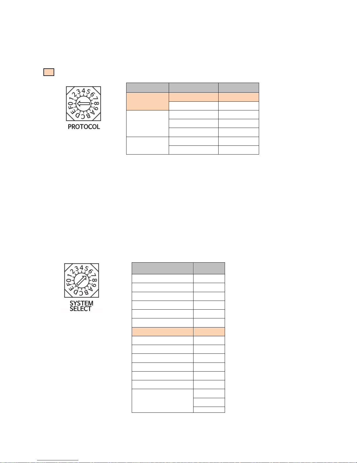
② PROTOCOL SETUP
Change the communication protocol as shown below.
: Factory Default
- Set the protocol correspond to the controller.
- Be sure to change the protocol while the power is off.
③ SYSTEM SELECT SETUP - VIDEO FORMAT
Set the video output format by changing the switch as shown below.
- Make sure to change the format while the power is off.
- HDMI, HD-SDI, DVI-I, CVBS(SD) simultaneous output.
※ For the stable use of camera, we recommend selecting P series for CVBS.
Protocol
BAUD RATE
Switch
VISCA
9600 bps
0
38400 bps
1
PELCO-D
2400 bps
2
9600 bps
3
38400 bps
4
PELCO-P
4800 bps
5
9600 bps
6
Output video format
Switch
1920x1080p60
0
1920x1080i60
1
1920x1080p30
2
1280x720p60
3
1280x720p30
4
1920x1080p59.94
5
1920x1080i59.94
6
1280x720p59.94
7
1920x1080p50
8
1920x1080i50
9
1920x 1080p25
A
1280x720p50
B
1280x 720p25
C
Reserved
D
E
F
4
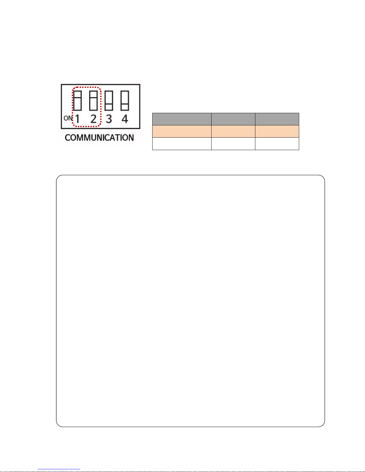
④ COMMUNICATION SETUP
(OFF: ↑ / ON:↓ )
Select RS-422 or RS-232C by using ON/OFF DIP switch no.1 and
2.
COMMUNICATION
1
2
RS-422
OFF
OFF
RS-232C
ON
OFF
MEMO
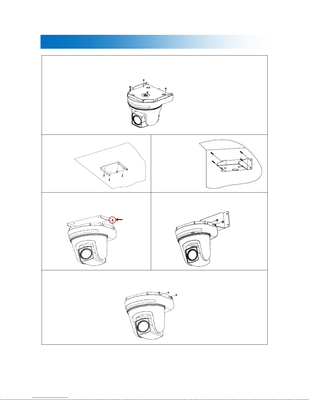
5
Bracket Installation
Fix the bracket to the bottom of the camera with screws (4EA).
Ceiling type
Wall mount type
Fix the camera into the ceiling bracket.
Fix the camera into the wall mount bracket.
Fix the camera using the 4 screws on both sides of the bracket.
Loosen slightly
a hexagon
6
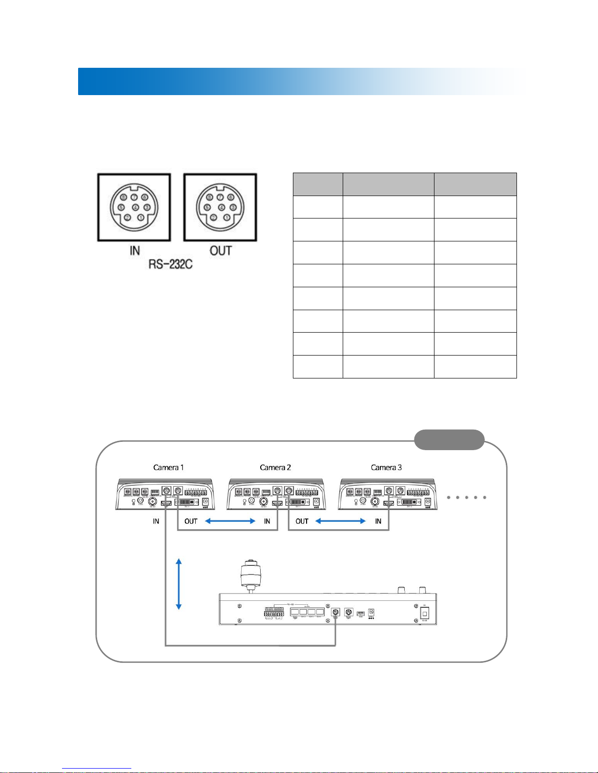
CAMERA CONNECTION
● RS-232C VISCA Connector (MINI DIN 8PIN, FEMALE)
PIN NO.
VISCA IN
VISCA OUT
1
DTR IN
DTR OUT
2
DSR IN
DSR OUT
3
TXD IN
TXD OUT
4
GND
GND
5
RXD IN
RXD OUT
6
GND
GND
7
NOT CONNECTED
NOT CONNECTED
8
NOT CONNECTED
NOT CONNECTED
SAMPLE
TVR-200H
 Loading...