

TV Logic 960H08, 960H16, 960H16R, 960H20R, 960H32R User Manual

1
Digital Video Recorder
User’s Manual
EYE-ON 960H Realtime
960H08/16/16R/20R/32R

2
Thank you for using our product.
Thank you for using our product.
1. This is user's manual for H.264 960H 08/16/20/32CH Realtime DVR (Digital
Video Recorder).
2. This manual contains product specification and introduction, installation guide,
operating guide and other necessary matters for easy understanding. Users should
read this user's manual carefully for proper use.
3. Contents in this manual may be changed according to the specification change and
feature improvement without any notification.
4. This user's manual shall never be copied without prior agreement and violating this
may be a reason for legal punishment on piracy.
5. If there is any incorrect or insufficient content in this user's manual, notify it to
Customer Support Center.

3
CONTENTS
Contents
CH 1. Product Introduction`
1-1. Product Contents 5
1-2. Specifications 7
1-3. Product Characteristics 9
1-4. Name of Each Part 11
CH 2. Installation Guide and Cautions
2-1. Cautions 18
2-2. Product Installation 21
2-2-1. Power Connection 21
2-2-2. Connecting External Device 21
CH 3. How to Use
3-1. General Usage Information 24
3-2. Live Mode 25
3-2-1. Live mode control 25
3-2-2. Live mode feature 27
3-3. Search Mode 35
3-3-1. Search selection type 35
3-3-2. Play Mode 39
3-4. Setup Mode 40
3-4-1. Display 40
3-4-2. Record 45
3-4-3. Device 50
3-4-4. Network 67
3-4-5. System 74
3-5. Firmware Upgrade 80

4
CONTENTS
Trouble Shooting 82
How to Connect xbox1 83
Contents
5
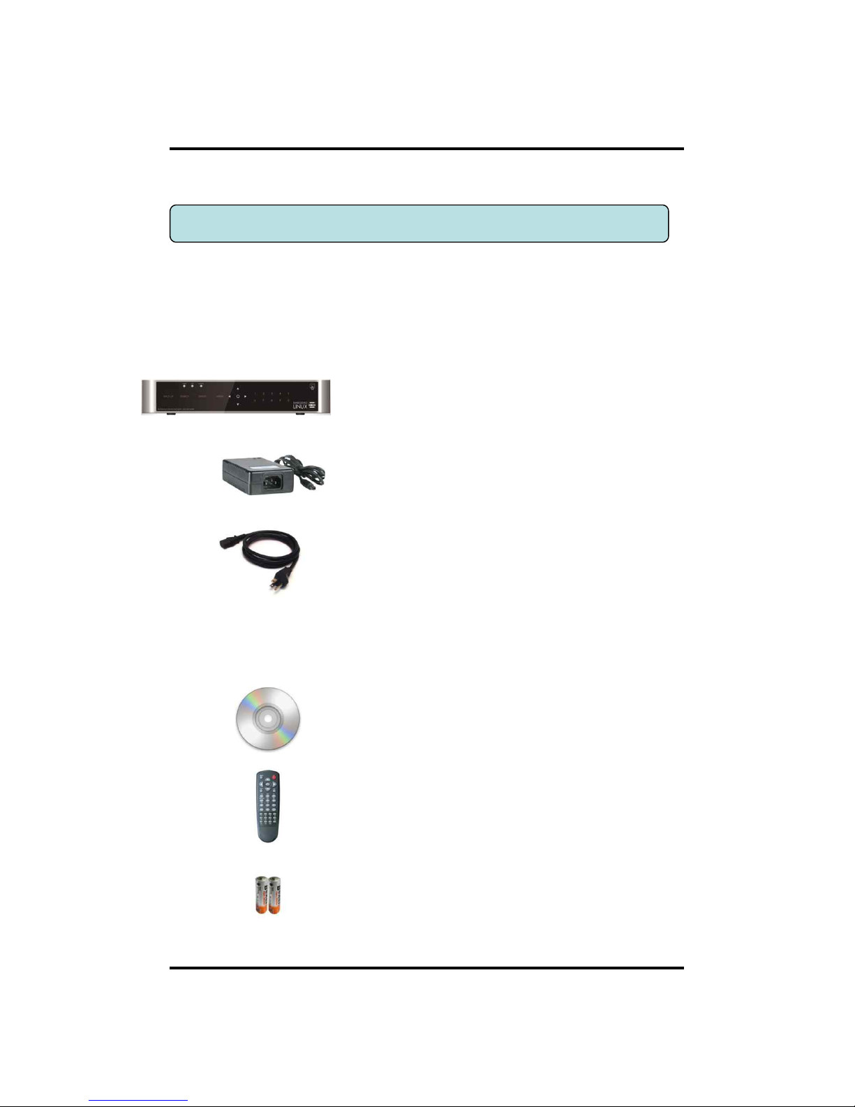
After removing packing materials of this product, check whether all following
contents are included.
Main Body (DVR):
This converts the analog video and audio signal to
the digital signal and saves on HDD.
Adapter:
This 12V adapter supplies power to the product.
Power Cable:
This connect the adapter and the power source.
Program CD:
This contains the User’s manual and Client
Program for DVR.
Remote Controller:
This is an IR remote controller for convenience.
Battery:
These are 2(two) battery for the remote controller.
CH1. Product Introduction
CH 1 Product Introduction
1-1. Product Contents (EYE-ON 960H08, 16)
6
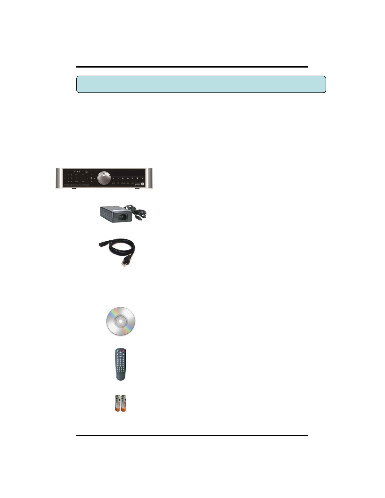
After removing packing materials of this product, check whether all following
contents are included.
CH 1 Product Introduction
Main Body (DVR):
This converts the analog video and audio signal to
the digital signal and saves on HDD.
Adapter:
This 12V adapter supplies power to the product.
Power Cable:
This connect the adapter and the power source.
Program CD:
This contains the User’s manual and Client
Program for DVR.
Remote Controller:
This is an IR remote controller for convenience.
Battery:
These are 2(two) battery for the remote controller.
1-1. Product Contents(EYE-ON 960H16R, 20R, 32R)
7
CH 1 Product Introduction
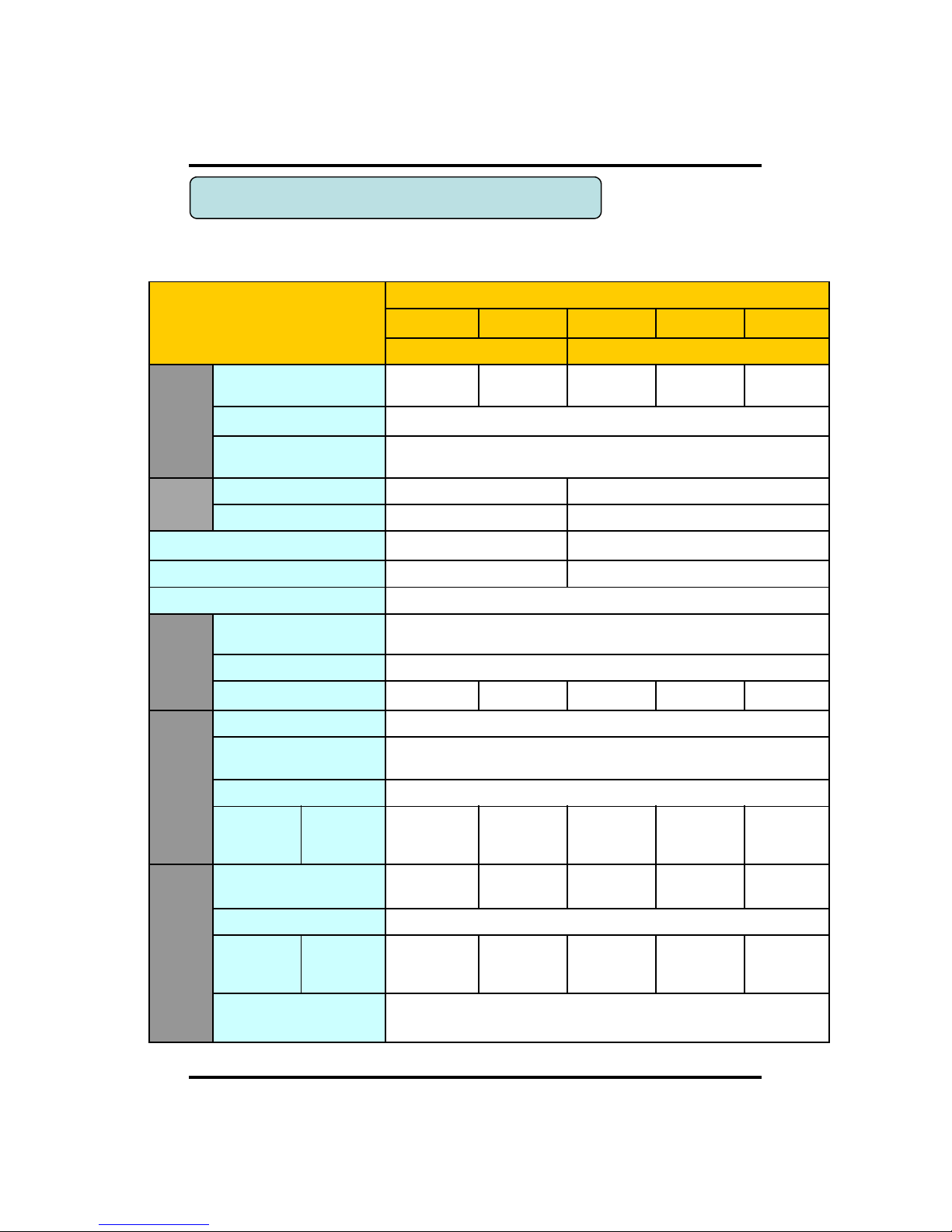
Model
EYE-ON 960H Realtime
960H08 960H16 960H16R 960H20R 960H32R
Compact case 19” rack type
Video
Camera input
8 BNC 16 BNC
16 BNC
(loop out)
20 BNC
(loop out)
32 BNC
Available source
Composite/960H/Mixed
Output
1 HDMI+1 VGA (simultaneously) / 1 Programmable SPOT with OSD
Audio
Audio input
4 RCA 16 RCA
Output
1 RCA 1 RCA
Sensor In
4 (NC, NO selectable) 16 (NC, NO selectable)
Alarm out
1 relay 14 TTL/ 2 relay
Operating System
Embedded Linux OS
Display
Speed
Real Time
Resolution (Pixel)
1280X1024, 1280X720, 1920X1080
Split screen
1,4,6,8 1,4,6,8,9,13,16 1,4,6,8,9,13,16
1,4,5,6,8,9,12,16,
17,20
1,4,5,6,8,9,12,16,
17,20,25,32
Recording
CODEC
H.264 / JPEG for 3G, Dual CODEC
Resolution (Pixel)
960H(960H), D1, WCIF, CIF, Mixed
Picture quality
4 steps (Super, High, Medium, Low)
Speed
NTSC area
PAL area
240fps@960H
200fps@960H
480fps@960H
400fps@960H
480fps@960H
400fps@960H
600fps@960H
500fps@960H
960fps@960H
800fps@960H
Playback
Display
1,4,6,8,9,13,16
1,4,5,6,8,9,12,16
1,4,6,8,9,13,16
1,4,5,6,8,9,12,16,
17,20
1,4,5,6,8,9,12,16
,17,20,25,32
Search mode
Calendar, Event ,POS , Panorama, Thumbnail
Speed
NTSC
PAL
240fps@960H
200fps@960H
120fps@960H
100fps@960H
480fps@960H
400fps@960H
300fps@960H
250fps@960H
480fps@960H
400fps@960H
Fast/Slow speed
Normal, REW & FF [recorded speed x2, x4, x8, x16,x32,x64,x1/2,x1/4],
Frame to frame, Pause
1-2. Specifications
8
CH 1 Product Introduction
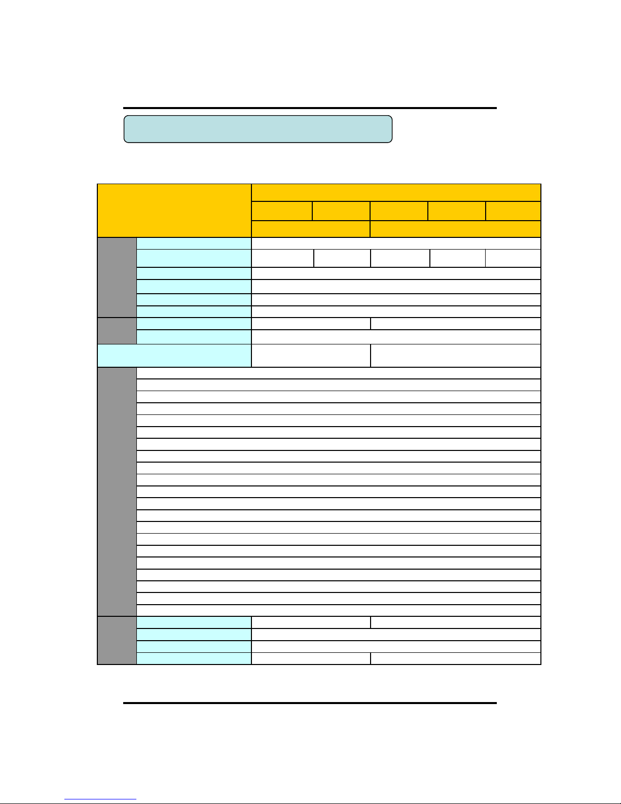
Model
EYE-ON 960H Realtime
960H08 960H16 960H16R 960H20R 960H32R
Compact case 19” rack type
Network
Network Interface
Gigabit Ethernet
Speed
100fps@720H 50fps@720H 100fps@720H
125fps@720H
200fps@720H
Protocol
TCP/IP, HTTP, DHCP
Application
Windows XP / 7 / 8 (PC Client system& IE)/MAC
Web Browser
Internet Explorer, Safari, FireFox, Chrome
Smart phone App
CatchEye : Android, iPhone for live and search
Backup
Interface
USB 2.0 X 2 USB 2.0 X 3
Backup device
External HDD, CD&DVD-RW, Network, Thumb Drive
The number of HDD
2 SATA(No capacity limit ;
4TB of more)
4 SATA + 1 eSATA(
upto
12 bays, No c
apacity limit ; 4TB or more)
Function
•Full GUI with alpha blending
•Individual setting of resolution, frame rates and picture quality
•Instant Replay
•Digital Zoom
•Mouse Control
•Weekly scheduler with holiday by 10 minutes setting
•Covert, Disable and Private function of cameras
•Motion Detection with 352 area setting
•Relay alarm output
•PTZ control by RS
-485
•Daylight Saving Time and Network Time Setting
•Multi User Authority up to 8 Users
•Deinterlacer
upon live and playback
•22
languages with full graphic
•Individual Network port setting
•Auto Deletion
•Import and Export the configuration
•Mirroring
•POS
Interface
•Dual CODEC engine for independent video transmission
•Interactive setup via network
Others
Power Consumption
60W
96W
Operating Temperature
5 ~40℃(41~104F)
Relative Humidity
Maximum 80% non-condensing
Dimension
340(W)
×250(D)×
60(H) mm
430(W)×420(D)×88(H)
1-2. Specifications

9
1) New Video Configuration optimized 16:9 widescreen
This is the revolutionary 8/16/20/32CH D1 real time DVR for 16:9 widescreen even
use the 4:3 video source. Also it displays real HD(1920X1080) resolution, and
therefore it provides the most clear image quality and the best security level.
2) High reliability
With Embedded hardware and software design, this maintains higher product
reliability.
3) Simple usage
This allows users to use it conveniently by placing control buttons similar to existing
ones on VCR, and users can easily learn the usage.
4) Pentaplex System
Pentaplex System allows live, recording, backup, networking and playback
simultaneously.
5) Selectable recording setup
For recording methods, users can select the frame rate, resolution and video quality
individually in order to be appropriate for user's environment.
6) Remote monitoring
With using exclusive line or Internet network, you can search or monitor recorded
images remotely by installing exclusive client program on Windows PC or Mac.
7) Backup
You can backup with a versitile external USB devices.
8) Audio recording
You can record 4 sound inputs simultaneously. Moreover, you can listen to the
sound in search and live monitoring and play mode.
9) Various recording methods
This provides convenient use with manual recording, recording by dates and days,
hourly schedule recording, sensor and motion detection event recording and others to
enable unmanned monitoring.
10) Various total monitoring features
You can cover any security scenario through various sensor inputs and contact output
control.
CH 1 Product Introduction
1-3. Product Characteristics

10
CH 1 Product Introduction
11) Display information in easy-to-understand information method
This enhanced convenience of user by displaying information (date, time, recording
method, recording frame number, HDD capacity and others) in monitoring, recording
and playing mode in easy-to-understand way.
12) P/T/Z control
By built in RS485, various P/T/Z cameras can be used.
13) Dual CODEC for video transmission
DVR can send 120 fps (based on CIF) regardless of the local recording and viewing
setup regardless with recording setup.
14) Web browser support
You can monitor and playback the video and control the PTZ camera by internet
explorer.
15) Built in S.M.A.R.T.
You can automatically check the health of the hard disk drives.
16) Language pack
Basically DVR has multiple language set, furthermore you can choose the language
set if you want.
17) Mirroring by internal HDD
If you install two HDDs, you can use the second HDD for backup for maximum
fault tolerance.
18) Spot monitoring
Spot out can be enable to monitor sequentially in other place.
19) Touch LED Switch
You can operate with touch LED switch in front panel.
20) Text inserter(POS Interface)
You can operate with the POS and ATM.
21) HD Spot out
You can use one of VGA and HDMI to the HD spot.
11
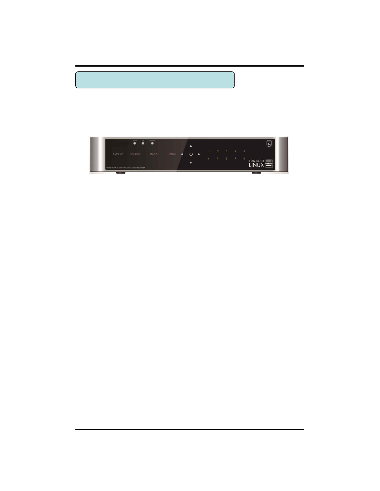
[Front Panel]
CH 1 Product Introduction
1. USB ports : These USB ports are for mouse and USB devices. You should
connect correctly the USB devices and mouse as picture directed.
2. Status lamps
POWER : Blue color back light. Power indicator.
RECORD : Red. Indicate the recording.
NETWORK : Green. Lit on connecting the network
3. ARROW, ENTER : This button is used to change settings for the product in
MENU Mode or used in Search Mode.
4. Function keys
1) MENU : It will move to the setup screen from the live mode.
2) SEARCH : It will change to the playback mode from the live mode.
3) BACKUP : It will move to the backup screen from the live or play mode.
5. Number buttons : If you press this button, it will be changed to full screen in live
viewing or playback If you want to go to 20ch, push the 10+ button twice.
(※ In menu and password setting, it is automatically converted to number buttons)
6. IR RECEIVER : It is for remote controller.
<EYE-ON 960H08, 16>
1-4. Name of Each Part
12
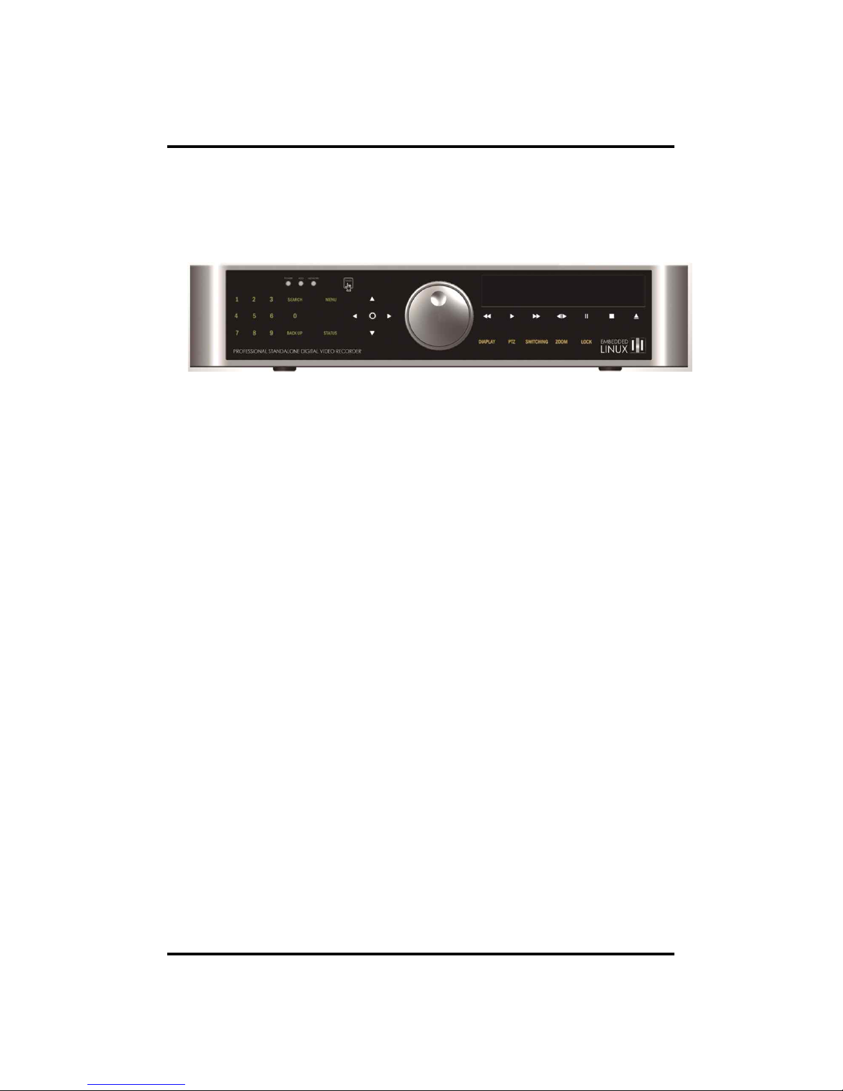
[Front Panel]
1. Playback buttons : It will be used on playback. If you press these buttons in live
mode, it will be automatically changed to the Instant Play mode. ‘Stop’ button
changes from the play mode to the live mode.
2. ARROW, ENTER : This button is used to change settings for the product in
MENU Mode or used in Search Mode.
3. Function keys
1) MENU : It will move to the setup screen from the live mode.
2) SEARCH : It will change to the playback mode from the live mode.
3) BACKUP : It will move to the backup screen from the live or play mode.
4) DISPLAY : It will change the screen splitting sequentially from 1 to 20. It can be
adapted both live and play mode.
5) SWITCHING : It will change to switching mode except 20 splitting.
6) ZOOM : It will go to the digital zoom directly.
7) PTZ : It will change to the pan, tilt and zoom control mode from the live mode.
8) LOCK/EXIT : If you want move to the upper menu or exit without saving, press
this button. On playback, it will disappear the search list for the better
viewing. On live viewing, it performs the system lock.
9) PANIC : This button is used in emergency status. If you push this button,
the DVR starts to record with maximum speed regardless of setting value.
4. Status lamps
POWER : Blue color back light. Power indicator.
RECORD : Red. Indicate the recording.
NETWORK : Green. Lit on connecting the network
ALARM : Red. It will be lit on when the events happen
5. USB ports : These USB ports are for mouse and USB devices.
6. IR Window : the window for remote controller
CH 1 Product Introduction
<EYE-ON 960H16R/20R/32R>
13
CH 1 Product Introduction
7. Number buttons : If you press this button, it will be changed to full screen in live
viewing or playback If you want to go to 20ch, push the 10+ button twice. Also 10+
button is used for ‘Hold’ while Jog Shuttle action.
(※ In menu and password setting, it is automatically converted to number buttons)
8. Backup device : You can use the versatile backup devices such as CD-RW and
DVD-RW.
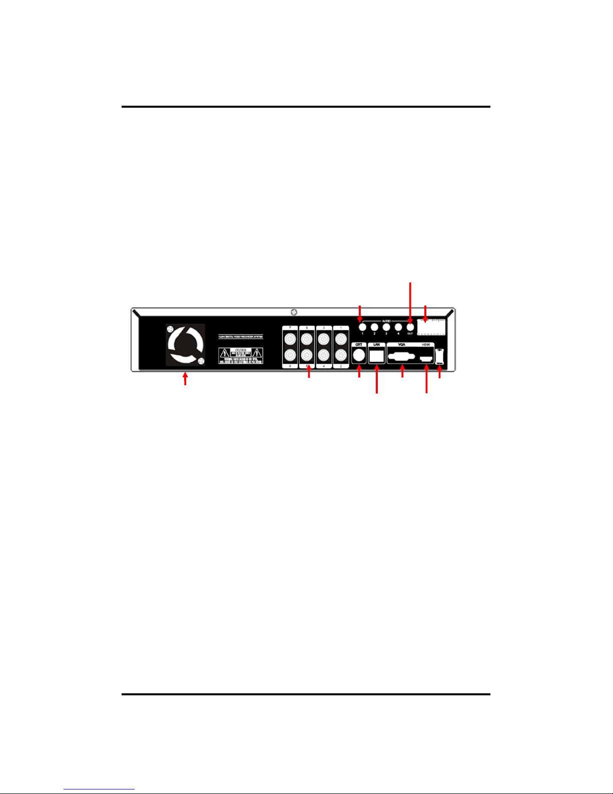
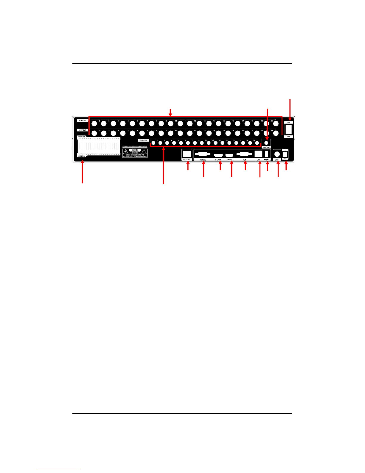
<EYE-ON 960H08>
[Rear Panel]
2.VIDEO IN
1.FAN
4. LAN
3.SPOT 5. VGA
6.HDMI
7. DC 12V
8.SENSOR IN / RELAY / RS485
10. AUDIO IN
1. Fan : Cooling Fan
2. VIDEO IN : This receives images from SDI cameras or any camera.
3. SPOT : For spot CRT monitor, composite signal comes out.
4. LAN : This is the Gigabit Ethernet LAN cable connection terminal.
5. VGA : video output for VGA display.
6. HDMI : Real HD(1920X1080) output for high resolution monitor.
7. DC 12V : DC12V 4.16A or up
8. SENSOR IN : This terminals can be connected to external sensors.
RELAY : This terminal blocks connect external electric devices to the product
(Warning Lamp and others).
RS485 : For control the pan and tile cameras. Make sure that the polarity.
9. AUDIO OUT : RCA audio out terminal.
10. AUDIO IN : RCA audio in terminals. You can record 4 channels at the same
time.
v For more details, refer to [CH 2. Installation Method and Cautions].
9. AUDIO OUT
14
CH 1 Product Introduction
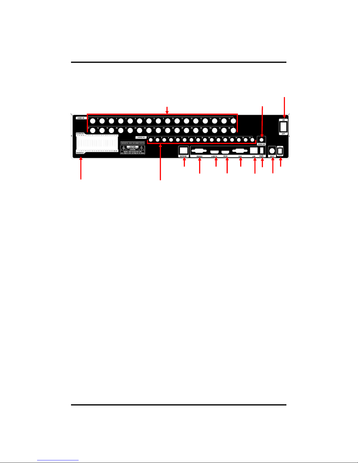
[Rear Panel]
<EYE-ON 960H16>
2.VIDEO IN
1.FAN
4. LAN
3.SPOT 5. VGA
6.HDMI
7. DC 12V
8.SENSOR IN / RELAY / RS485
10. AUDIO IN
9. AUDIO OUT
1. Fan : Cooling Fan
2. VIDEO IN : This receives images from SDI cameras or any camera.
3. SPOT : For spot CRT monitor, composite signal comes out.
4. LAN : This is the Gigabit Ethernet LAN cable connection terminal.
5. VGA : video output for VGA display.
6. HDMI : Real HD(1920X1080) output for high resolution monitor.
7. DC 12V : DC12V 4.16A or up
8. SENSOR IN : This terminals can be connected to external sensors.
RELAY : This terminal blocks connect external electric devices to the product
(Warning Lamp and others).
RS485 : For control the pan and tile cameras. Make sure that the polarity.
9. AUDIO OUT : RCA audio out terminal.
10. AUDIO IN : RCA audio in terminals. You can record 4 channels at the same
time.
v For more details, refer to [CH 2. Installation Method and Cautions].

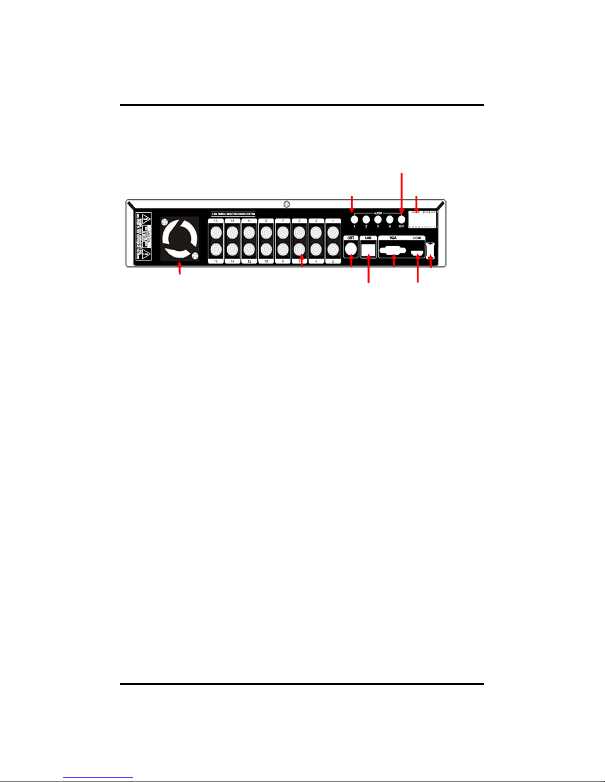
15
1. SENSOR IN : This terminals can be connected to external sensors.
RELAY : This terminal blocks connect external electric devices to the product
(Warning Lamp and others).
RS485 : For control the pan and tile cameras. Make sure that the polarity.
2. AUDIO IN : RCA audio in terminals. You can record 16 channels at the same
time.
3. EXTEND (option) : Connect EXTEND FTP cable to VGA or HDMI Receiver
4. RS232C : This is Serial communication(RS232C) cable connection terminal.
5. e-SATA
6. HDMI : Real HD(1920X1080) output for high resolution monitor
7. VGA : video output for VGA display
8. LAN : This is the Gigabit Ethernet LAN cable connection terminal.
9. USB : This USB port is for mouse and USB devices.
10. SPOT : For spot CRT monitor, composite signal comes out.
11. DC 12V : DC12V 12.5A or up
12. Power Switch(ON/OFF)
13. AUDIO OUT : RCA audio out terminal.
14. VIDEO IN : This receives images from cameras and sends them to monitors.
Loop Out : This sends the images from the cameras to the other devices.
v For more details, refer to [CH 2. Installation Method and Cautions].
CH 1 Product Introduction
1. SENSOR IN / RS485, ALARM OUT
14.Video In, Loop Out
8. LAN
5. e-SATA
7. VGA
6. HDMI
12. POWER SWITCH
10. SPOT
3. EXTEND
4. RS232C
2. Audio In
11. DC 12V
9. USB
13. AUDIO OUT
<EYE-ON 960H16R>
[Rear Panel]
16
CH 1 Product Introduction
<EYE-ON 960H20R>
[Rear Panel]
1. SENSOR IN / RS485, ALARM OUT
14.Video In, Loop Out
8. LAN
5. e-SATA
7. VGA
6. HDMI
12. POWER SWITCH
10. SPOT
3. EXTEND
4. RS232C
2. Audio In
11. DC 12V
9. USB
13. AUDIO OUT
1. SENSOR IN : This terminals can be connected to external sensors.
RELAY : This terminal blocks connect external electric devices to the product
(Warning Lamp and others).
RS485 : For control the pan and tile cameras. Make sure that the polarity.
2. AUDIO IN : RCA audio in terminals. You can record 16 channels at the same
time.
3. EXTEND (option) : Connect EXTEND FTP cable to VGA or HDMI Receiver
4. RS232C : This is Serial communication(RS232C) cable connection terminal.
5. e-SATA
6. HDMI : Real HD(1920X1080) output for high resolution monitor
7. VGA : video output for VGA display
8. LAN : This is the Gigabit Ethernet LAN cable connection terminal.
9. USB : This USB port is for mouse and USB devices.
10. SPOT : For spot CRT monitor, composite signal comes out.
11. DC 12V : DC12V 12.5A or up
12. Power Switch(ON/OFF)
13. AUDIO OUT : RCA audio out terminal.
14. VIDEO IN : This receives images from cameras and sends them to monitors.
Loop Out : This sends the images from the cameras to the other devices.
v For more details, refer to [CH 2. Installation Method and Cautions].
17
1. SENSOR IN : This terminals can be connected to external sensors.
RELAY : This terminal blocks connect external electric devices to the product
(Warning Lamp and others).
RS485 : For control the pan and tile cameras. Make sure that the polarity.
2. AUDIO IN : RCA audio in terminals. You can record 16 channels at the same
time.
3. EXTEND (option) : Connect EXTEND FTP cable to VGA or HDMI Receiver
4. RS232C : This is Serial communication(RS232C) cable connection terminal.
5. e-SATA
6. HDMI : Real HD(1920X1080) output for high resolution monitor
7. VGA : video output for VGA display
8. LAN : This is the Gigabit Ethernet LAN cable connection terminal.
9. USB : This USB port is for mouse and USB devices.
10. SPOT : For spot CRT monitor, composite signal comes out.
11. DC 12V : DC12V 12.5A or up
12. Power Switch(ON/OFF)
13. AUDIO OUT : RCA audio out terminal.
14. VIDEO IN : This receives images from cameras and sends them to monitors.
Loop Out : This sends the images from the cameras to the other devices.
v For more details, refer to [CH 2. Installation Method and Cautions].
CH 1 Product Introduction
1. SENSOR IN / RS485, ALARM OUT
14.Video In, Loop Out
8. LAN
5. e-SATA
7. VGA
6. HDMI
12. POWER SWITCH
10. SPOT
3. EXTEND
4. RS232C
2. Audio In
11. DC 12V
9. USB
13. AUDIO OUT
<EYE-ON 960H32R>
[Rear Panel]
18
CH2. Installation Method and Cautions
2-1. Cautions
- Avoid installing the product where there are direct rays or it is hot by locating near
from heat generator. (May cause fire)
- Do not put vase, flowerpot, cup, cosmetics, drug, and anything the contain water on
product. (May cause fire or electric shock, and it may injure people by falling)
- Do not insert or drop any metal object (coin, hair pin) or flammable object (match,
paper) into air hole. (May cause fire or electric shock)
- Do not put any heavy object on it. (May injure people by being fell or destroyed.)
- Put power plug surely not to be moved. (If not, this may cause fire.)
- Unplug power plug and antenna when there are thunders and lightening. (May
cause fire.)
- For cleaning the product, wipe surface with dry towel. Using chemical agent or
cleaner may change the color and unpeel paint. Do not put several plugs at same
time. (May cause electric shock.) If there is smoke or strange smell, stop operation. In
this case, turn the power off and unplug it, and then contact our service center. (If you
keep using it, this may cause fire or electric shock.)
- Do not unplug by pulling cord. (If cord is damaged, it may cause fire or electric
shock.)
- Do not plug or unplug with wet hands. (May cause electric shock.)
WARNING
Risk of electric shock.
Do not open the cover of the product.
Servicing of this product by unauthorized personnel is prohibited
and will result in a void of warranty.
In order to ensure the most stable conditions for power, the use
of a UPS (Uninterrupted Power Supply) is recommended.
CH 2 Installation Method and Cautions

19
- Keep the power cord untwisted. (May cause fire or electric shock.)
- Use proper adapter. (Using too much electric power may cause fire or electric shock.)
- Do not install it at where exposed to rain and wind and water drop. (May cause fire,
electric shock and transformation.)
- Keep away from fire. (May cause fire.)
-Do not disassemble or remodel on your own. (May cause malfunction or electric
shock.)
- Do not put next to flammable materials like flammable spray. (May cause fire.)
- Do not install it at a place with too much dirt. (May cause fire.)
- Do not install it on unstable places like shaking table and inclined place or shaking
place. (May injure users by falling down or being upside down.)
- Do not put an heavy object on power cord or avoid it from being pressed by the
device. (May cause fire or electric shock.)
- In case of using extension cord, do not use several devices at same time. (May cause
fire with abnormal heating of extension.)
- When there are dirt on power plug pin or power outlet, clean it nicely. (May cause
fire.)
-Do not damage on power cord or plug, and bend or twist or pull too much, and put it
between other objects or heat. If power outlet insertion part is not tight, do not use it.
(May cause fire or electric shock.)
-Do not drop or give a shock to the product. (May injure people or cause malfunction.)
- Do not touch power adaptor or signal controller. (May cause electric shock.)
- Do not put any object too close to block cooling fan. (May cause fire.)
- In case of exchanging batteries with improper type, there might be danger of
explosion.
- For used batteries, throw away separately from other garbage.
- When you take out batteries, avoid children from eating them by mistake. Keep them
away from children. (If a child ate them, contact a doctor right away.)
CH 2 Installation Method and Cautions

20
Note :
This equipment has been tested and found to comply with the limits for a Class A
digital device, pursuant to part 15 of the FCC Rules. These limits are designed to
provide reasonable protection against harmful interference when the equipment is
operated in a commercial environment. This equipment generates, uses and can
radiate radio frequency energy and, if not installed and used in accordance with the
instruction manual, may cause harmful interference to radio communications.
Operation of this equipment in a residential area is likely to cause harmful
interference in which case the user will be required to correct the interference at his
own expense. Changes or modifications to this equipment may cause harmful
interference unless the modifications are expressly approved in the instruction
manual. The user could lose the authority to operate this equipment if an
unauthorized change or modification is made.
This device complies with the part 15 of the FCC Rules. Operation is subject to the
following two conditions : (1) this device may not cause harmful interference, and (2)
this device must accept any interference received, including interference that may
cause undesired operations.
FCC Warning :
This equipment may generate or use radio frequency energy. Changes or
modifications to this equipment may cause harmful interference unless the
modifications are expressly approved in the instruction manual. The user could lose
the authority to operate this equipment if an unauthorized change or modification is
made.
CE Warning : This is a Class A product. In a domestic environment this may cause
radio interference in which case the user may be required to take adequate measures.
This product has obtained EMI registration.
CH 2 Installation Method and Cautions
21
CAMERA
MIC
CH 2 Installation Method and Cautions
2-2 Product Installation
This product may be composed of camera and monitor in default, and additionally
the sensor, microphone, speaker and PC for network can be connected if necessary.
2-2-1. Power Connection
1) Connect adapter cable to power connection terminal at rear side.
2) Input AC power to the adapter. (free voltage from 100V to 240V, 50/60Hz)
※ You must operate it at the rated voltage instructed on the user's manual. In case
power higher than the rated voltage is supplied, it may cause damages on product.
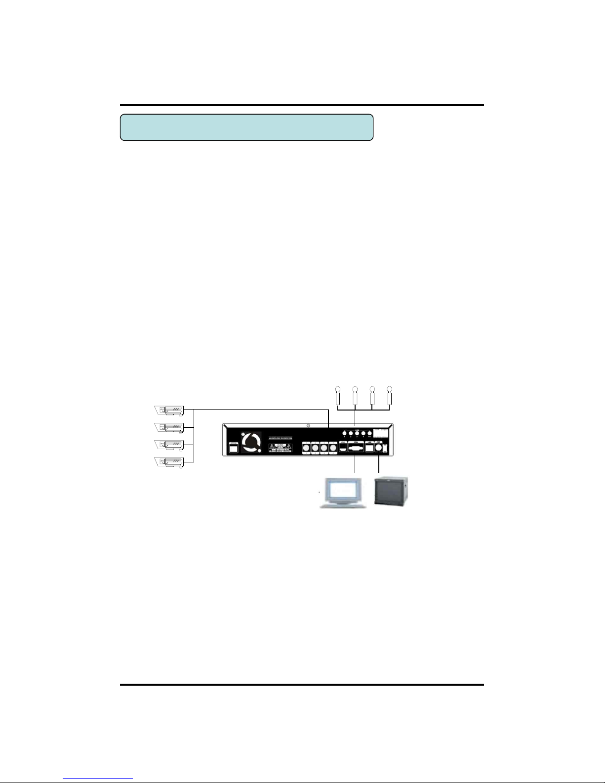
2-2-2. Connecting External Device
※ Connect it when power of the product is off.
※ Read through user's manual for the device you are connecting carefully.
1) How to Connect External Video/Audio Device
Connect cameras to VIDEO IN by channels.
Connect microphone (AMP) to AUDIO IN by channels.
Connect VIDEO OUT to VIDEO IN of monitor.
Connect HD output to HD Monitor.
Connect AUDIO OUT to AUDIO IN of monitor (or speaker).
Connect Spot output to Composite Monitor.
22
CH 2 Installation Method and Cautions
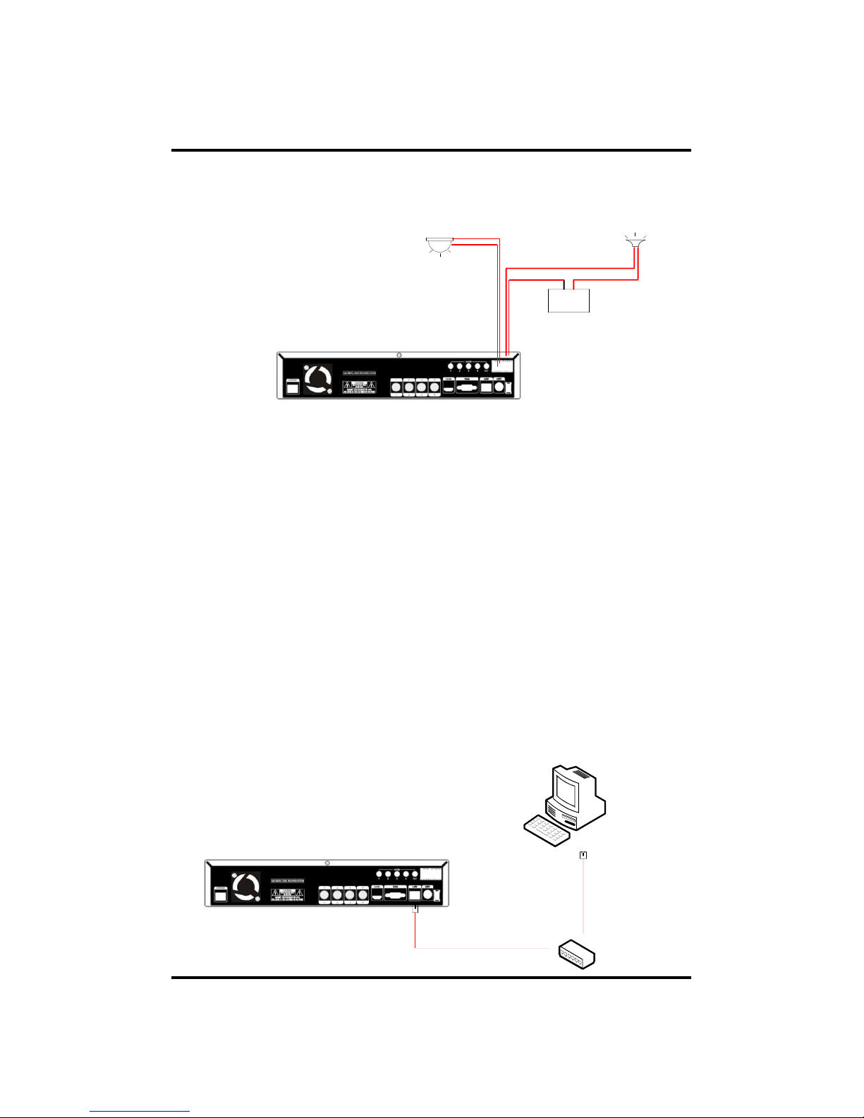
2) How to connect external sensor
Sensor terminal is composed of 1 input channel and 1 output channel. Sensor out
terminal is relay output with 1A, 24V or 0.5A,125V.
SIREN
POWER
- +
SENSOR
Sensor In : Connect the sensors. The sensor are composed of both signal and ground
terminals, with a voltage difference of 5V. In the case that the sensor used for input
is of the N/O (Normal Open) type, when the voltage difference between the signal
and ground falls to 0V (short), the DVR can use this as a trigger to start alarm/sensor
based recording.
Sensor Out : Connecting external electrical devices
The relay output terminal does not provide power, and functions only on an ON/OFF
basis via a relay. Normally, the signal and ground should be on an OPEN basis, and
the DVR will complete the relay connection.
3) Connecting with PC using LAN cable
If you want to connect DVR to PC directly, use LAN cable, and if you want to
use HUB, connect cable via hub.
*Hub : This is a device connecting one office to devices located near with using
cable when you organize LAN
*Cable : This is standard UTP cable used for communication among
devices through Hub and others when you organize LAN
PC
HUB
23
CH 2 Installation Method and Cautions
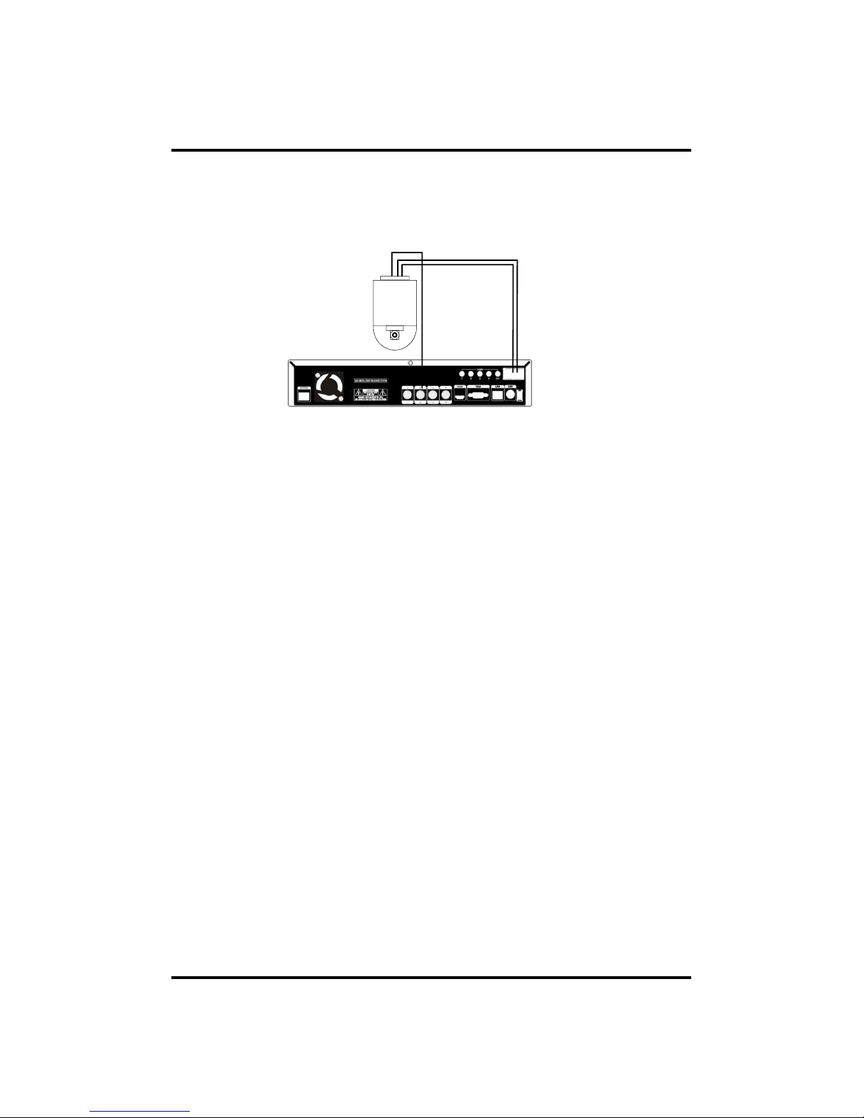
4) Connection Using PTZ camera
In case of using pan and tilt cameras, connect PAN/TILT DRIVE to product as
shown at following figure.
RS485 CABLE
VIDEO CABLE
SPEED
DOME
5) Installing Hard disk drive
In case of installing the hard disk drive, open the upper case and install the hard disk
drive on the hard bracket. Remember that the main power should be off to install the
hard disk drive. If you have any trouble, please contact the technical support.
24
CH3. How to Use
3-1. General Usage Information
CH 3 How to Use
The DVR system can be operated with a mouse or remote controller under the
four main modes listed below:
Live Mode – This is the “main or default” mode. From this mode you can
view in real time all currently operating cameras, information regarding
camera status, and have access to Pan/Tilt camera controls. In addition,
system status information will be shown during live mode, and other modes
can be entered from Live mode.
Setup Mode – The user will be able to customize settings for Live viewing,
Recording, Backup, and Camera related devices under the Setup Mode.
Search Mode – In Search Mode, the user will be able to review all recorded
footage in the case that an event must be reviewed using a calendar or event
based search.
Backup Mode – In Backup Mode, the user will be able to archive the desired
data to the preferred supported media of their choice (ex. CD, DVD, USB
Backup, Remote Client Software, etc.)
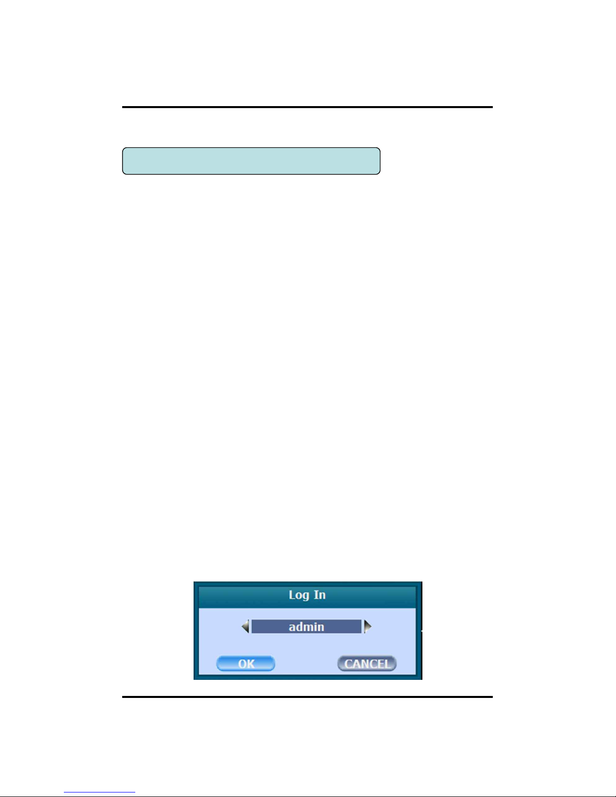
Password Protection – The DVR system will utilize a user ID and password
system to prevent unauthorized usage of this product. Control of the system
will only be possible after entering a proper ID and password as illustrated
below. (Factory Default settings are blank for these fields).
IDs and passwords should be managed by a system administrator, as different
users may be given different levels of access to the DVR.

25
Recording indicator
Event recording indicator
Motion detection indicator
Sensor activation indicator
POS indicator
CH 3 How to Use
3-2. LIVE Mode
In this section you will know how to split the video mode into 1, 4, 6, 8, 9, 12, 16, as
well as auto sequencing, PTZ Control, Mouse control, Setup configurations, Backup.
3-2-1. LIVE Mode Control
1) Live View Status
You may use the Live Menu Bar located at the bottom for quick shortcuts and view
status of certain items.
2) Live Menu Bar
You may use the Live Menu Bar located at the bottom for quick shortcuts and view
status of certain items.
Date
Time
Screen Split mode change
Sequence activation
Hard drive usage
Lock/ Unlock indicator
Scheduler activation indicator
Network connection indicator
Audio out channel indicator
Audio Mute indicator
26
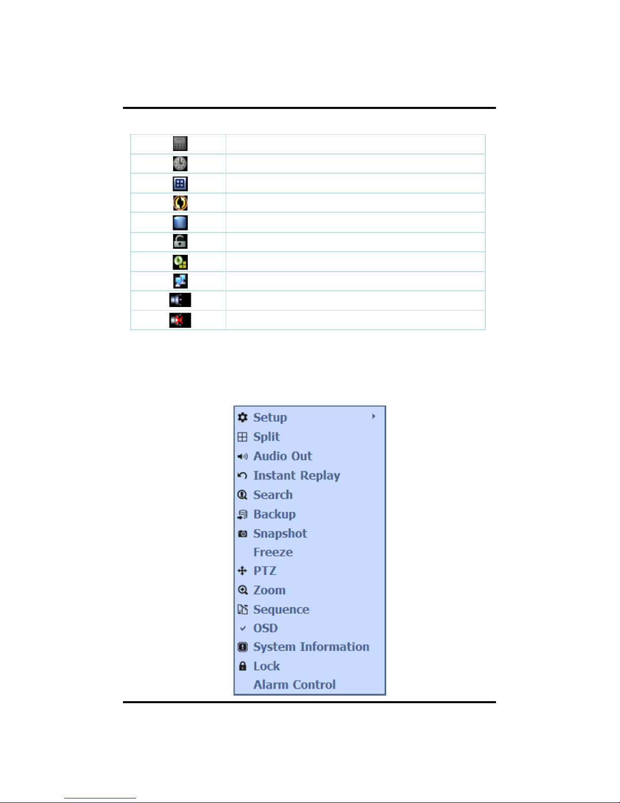
3) Live Popup Menu
By Right-Clicking anywhere on Live Screen, you may view the Live Popup Menu.
By using the Live Popup Menu, you can quickly jump to the necessary configuration
and settings.
CH 3 How to Use
 Loading...