

Page 1

TECHNICIAN
MANUAL
Table -Top Autoclaves
models 1730, 2340, 2540, 3140, 3850, 3870 M & MK
1730MK Valueklave
Cat. No. MAN205-0309001EN Rev. F
Tuttnauer Europe b.v., Paardeweide 36, 4824 EH, Breda, P.O. Box 7191, 4800 GD Breda, Netherlands. +31/76-5423510, Fax: +31/76-5423540
Page 2

Page 3

TABLE OF CONTENTS
PARAGRAPH PAGE NO.
1 INTRODUCTION ........................................................................................3
2 PERIODICAL TESTS .................................................................................3
3 SYMBOL DESCRIPTION...........................................................................3
4 SAFETY INSTRUCTIONS..........................................................................4
5 WATER QUALITY ......................................................................................5
5.1 Water for Generating Steam .............................................................5
5.2 Reverse Osmosis................................................................................5
6 MAINTAINING AND REPLACING PARTS ...........................................10
6.1 Safety Tests after Repair .................................................................10
6.2 Dismantling the Outer Cover of the Autoclave...............................11
6.3 Cleaning and Replacing Air Trap Jet.............................................12
6.4 Replacing the Safety Valve .............................................................13
6.5 Replacing the circuit breaker..........................................................14
6.6 Temperature Safety Thermostat......................................................15
6.7 Raising the Working the Temperature of the Safety Thermostat...15
6.8 Cut-Off Thermostat.........................................................................16
6.9 Replacing Heating Elements...........................................................17
6.10 Replacing Multi-Purpose Valve ......................................................18
6.11 Unclogging the multi-Purpose Valve or Chamber .........................20
6.12 Pressure Door Lock System ............................................................20
6.13 Replacing the Door Bellows............................................................ 21
6.14 Replacing the thermostat B10.........................................................22
6.15 Replacement of the Door Cover ......................................................23
6.16 Replacing the Locking Device.........................................................24
6.17 Replacing the Door Switch (models 2540, 3150, 3850, 3870) ........ 25
6.18 Replacing the Drain Valve..............................................................26
7 TROUBLESHOOTING .............................................................................27
8 LIST OF SPARE PARTS...........................................................................35
9 PRESSURE VS TEMPERATURE FOR SATURATED STEAM .............39
1
Page 4

TABLE OF CONTENT (Cont.)
DRAWINGS PAGE NO.
Front View Model 1730 M, MK-Valueklave................................................................6
Front View Model 2340/2540 M, MK ..........................................................................7
Front View Model 38500/3870 M, MK ........................................................................8
Rear View ......................................................................................................................9
General View of Vessel, Door and Accessories .........................................................31
Autoclave Cover ..........................................................................................................32
Door Tightening Bolt – Assembly ..............................................................................33
Multi-Purpose Valve Assembly................................................................................... 34
Drawing of Electrical System of Table Autoclave Models 1730M, MK ................... 43
Drawing of Electrical System of Table Autoclave Models 2340/2540 M, MK .........44
Drawing of Electric System of Table Autoclave Model 3140 M ............................... 45
Drawing of Electric System of Table Autoclave Models 3850 M.............................. 46
Drawing of Electrical System of Table Autoclave Models 3870 M...........................47
Piping Diagram Table Top Autoclave Models: M And MK......................................48
2
Page 5
1 INTRODUCTION
This manual, together with the operator’s manual, forms the complete edition
of the Operation and Maintenance instructions. This manual is intended for the
use of the technician. It is forbidden for unqualified and unauthorized
personnel to service the autoclave in accordance with the instructions in this
manual. Any unauthorized service may result in the invalidation of the
manufacturer’s guarantee.
The qualified technician shall be an authorized electrician with the right
qualifications in electronics and shall be familiar with the local
technical/electrical regulations.
2 PERIODICAL TESTS
PERIOD TEST
1 months Test the safety valve by operating it.
6 months
Remove the autoclave’s cover, tighten the heaters’ screws and
electrical connections and valves.
Check the continuity of the grounding connections.
Perform validation of the autoclave.
Check the precise operation of the earth leakage relay.
Check that the autoclave is leveled.
Check the safety elements; safety valve, door locking bellows and
door locking mechanisms.
Year
Run the autoclave and verify that it operates as specified.
Check the water reservoir, piping, plastic parts and electric wires.
Check and tighten the piping joints to avoid leakage.
Check and tighten all screw connections, heaters and valves and
instrumentation.
Calibrate the temperature and pressure once a year or in reference to
local rules or regulations (refer to the section on Calibration).
5 years Observe the closing device for excessive wear
Safety tests (pressure vessel, efficiency, electrical) shall be performed in
accordance with local rules or regulations, by an authorized inspector.
Only an authorized technician shall perform the 6-months and yearly tests!
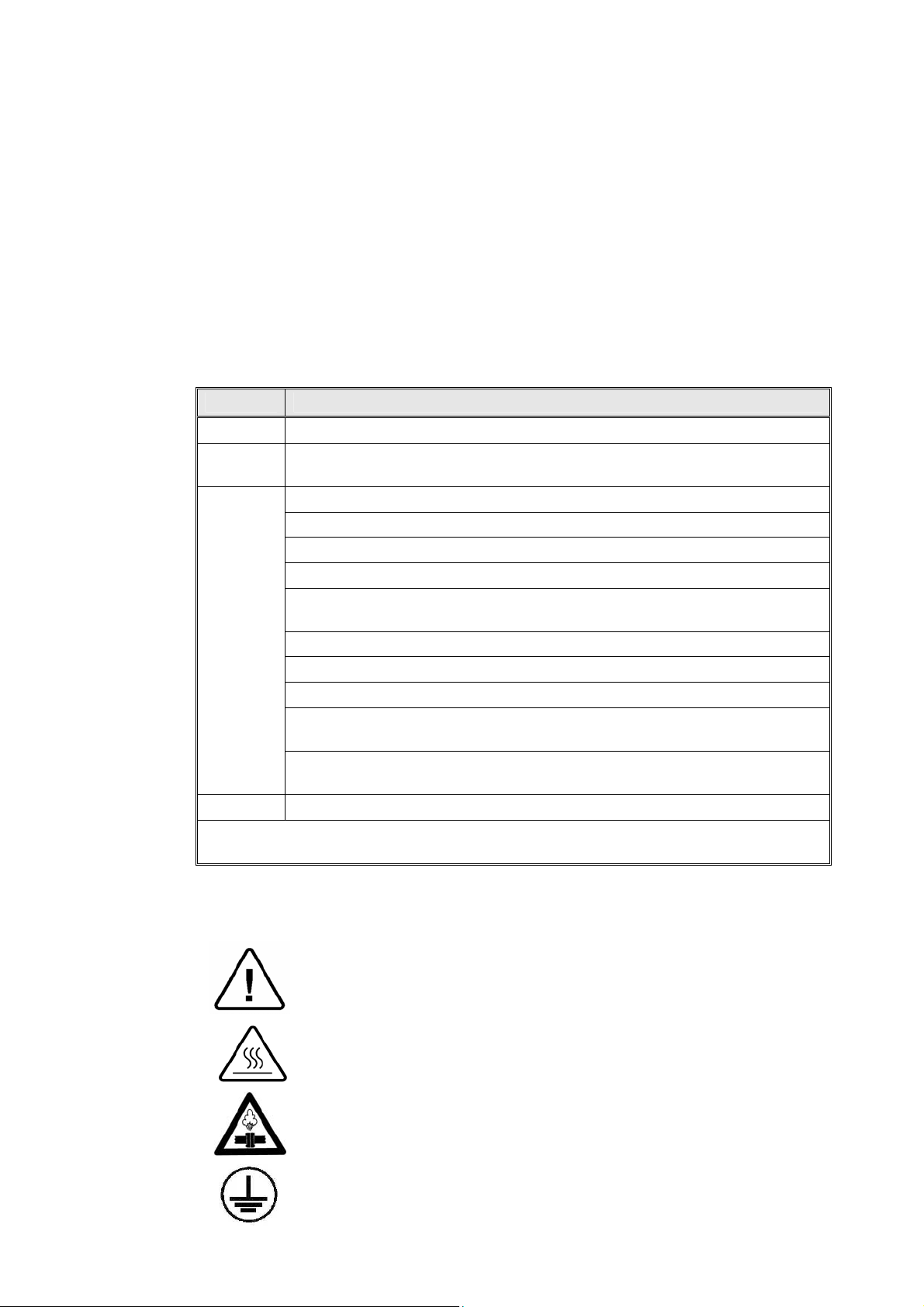
3 SYMBOL DESCRIPTION
Caution! Consult accompanying documents
Caution! Hot Surface.
Caution! Hot steam.
Ground
3
Page 6

4 SAFETY INSTRUCTIONS
The autoclave has unique characteristics. Please read and understand the
operation instructions before first operation of the autoclave. The following
issues may require instructions guidance provided by the manufacturer: how to
operate the autoclave, the door safety mechanism, the dangers involved in
circumventing safety means, how to ensure that the door is closed, and how to
select a correct sterilization program.
Autoclave maintenance is crucial for the correct and efficient function of the
device. We enclose a log booklet that includes maintenance recommendations,
with every device.
1. Make sure that you know where the main power switch is.
2. Never use the autoclave to sterilize corrosive products, such as: acids,
bases and phenols, volatile compounds or solutions such ethanol,
methanol or chloroform nor radioactive substances.
3. All autoclave users must receive training in proper usage from an
experienced employee. Every new employee must undergo a training
period under an experienced employee.
4. A written procedure must be established for autoclave operation,
including: daily safety tests, seal inspection and door hinge inspection,
smooth action of the closing mechanism, chamber cleaning, prevention
of clogging and preservation from corrosion, what is permitted and what
is prohibited for sterilization and choosing a sterilization program.
5. Before use, check inside the autoclave chamber to ensure that no items
have been left from the previous cycle.
6. Load trays in such a way as to allow steam to move freely among all
items.
7. Do not attempt to sterilize liquids since this autoclave is not intended to
sterilize liquids.
8. When sterilizing plastic materials, make sure that the item can withstand
sterilization temperature. Plastic that melts in the chamber is liable to
cause a great deal of damage.
9. On closing the device door, make sure it is properly locked before
activating.
10. Verify once again that you have chosen the appropriate sterilization
program.
11. Before withdrawing trays, wear heat resistant gloves.
12. Before opening the door, verify that there is no pressure in the chamber
(chamber pressure gauge is located on the autoclave's front panel).
13. Open the door slowly to allow steam to escape and wait 5 minutes
before you remove the load.
14. Once a month, ensure that the safety valves are functioning, and once
annually a certified tester must conduct pressure chamber safety tests.
15. Once annually, or more frequently, effective tests must be performed,
i.e., calibration and validation.
16. Examine the condition of assemblies on a regular basis. Make sure there
are no leaks, breaks, blockages, whistles or strange noises.
17. It is required to conduct maintenance operations as instructed.
18. Immediately notify the person in charge of any deviation or risk for the
proper function of the device.
4
Page 7

5 WATER QUALITY
5.1 Water for Generating Steam
The distilled or mineral – free water supplied to the sterlizer shall be
according to the table below:
Physical Characteristics and Maximum acceptable contaminants
(In compliance with ISO 11134 and ISO 13683).
levels in water or steam, for sterlizers
Evaporate residue
Silica
Iron
Cadmium
Lead
Rest of heavy metals
Chloride
Phosphate
Conductivity
≤15 mg/l
≤ 2 mg/l
≤ 0.2mg/l
≤ 0.005 mg/l
≤ 0.05 mg/l
≤ 0.1 mg/l
≤ 3 mg/l
≤ 0.5 mg/l
≤ 50 µs/cm
pH 6.5 to 8
Appearance colorless, clean, without sediment
Hardness
≤ 0.1 mmol/l
Compliance with the above data should be tested in accordance with
acknowledged analytical methods, by an authorized laboratory.
Attention:
We recommend testing the water quality once a month. The use of
water that does not comply with the table above may have severe
impact on the working life of the sterilizer and can invalidate the
manufacturer’s guarantee.
5.2 Reverse Osmosis
A Reverse Osmosis system may be used to improve the quality of the
water used to generate steam in the autoclave chamber. The use of
mineral free will contribute to better performance and longer life of the
autoclave.
5
Page 8
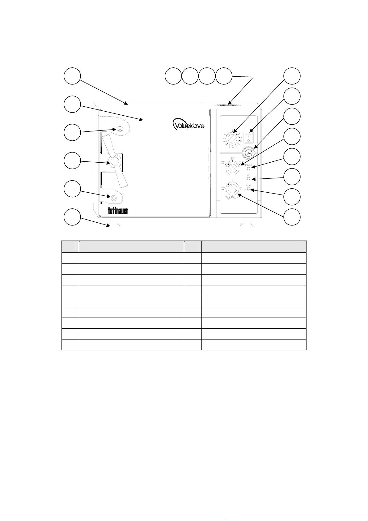
FRONT VIEW MODEL 1730 M, MK-Valueklave
18
17
16
15
14
13
No. description No. description
1 2 3 4
5
6
7
8
9
10
11
12
1. Water reservoir cover 10. Dry indicator light
2. Water reservoir 11. Heat indicator light
3. Safety valve 12. Multipurpose valve
4. Air trap jet 13. Front legs
5. Timer 14. Reservoir water drain valve
6. Main power switch 15. Door Closing Device
7. Pressure gauge 16. Door Micro-switch
8. Thermostat (B10) knob 17. Door cover
9. Power indicator light 18. Autoclave cover
6
Page 9
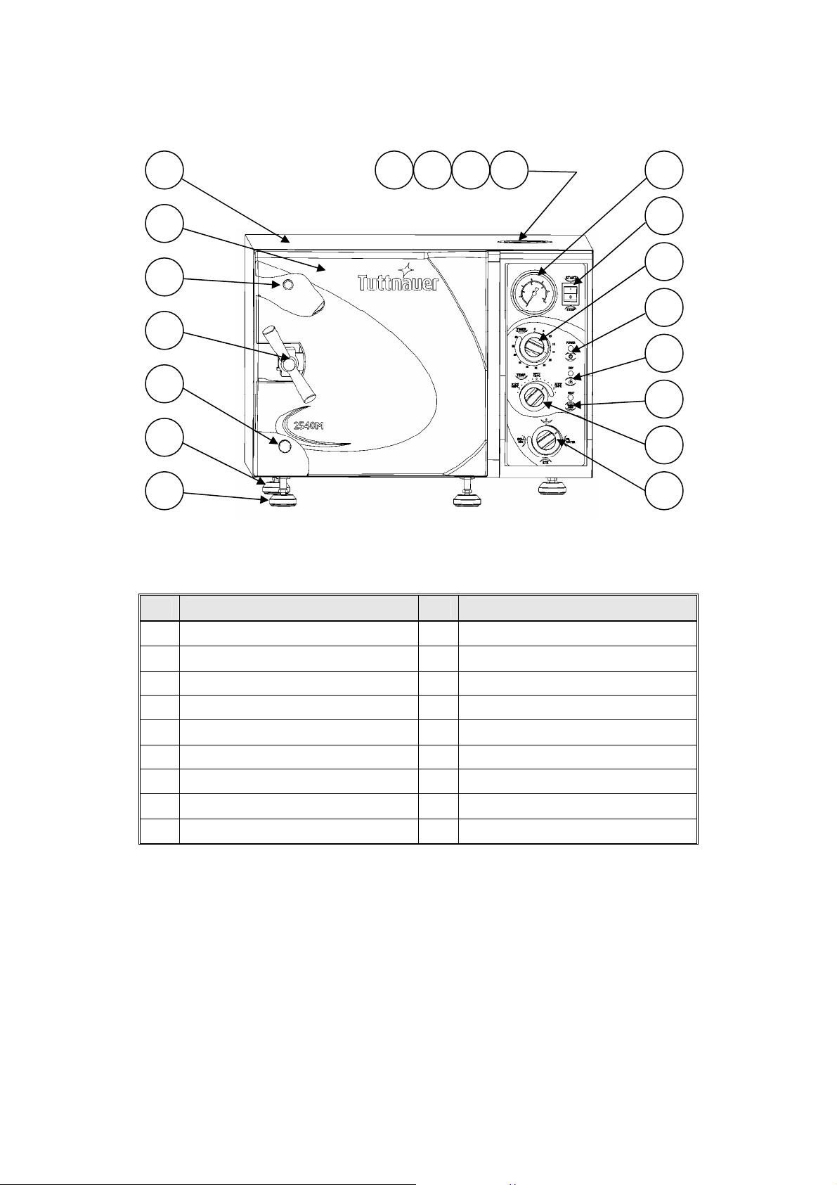
FRONT VIEW MODEL 2340/2540 M, MK
19
18
17
16
15
14
13
No. description No. description
1 2 3 4
5
6
7
8
9
10
11
12
1. Water reservoir cover 10. Heat indicator light
2. Water reservoir 11. Thermostat (B10) knob
3. Safety valve 12. Multipurpose valve
4. Air trap jet 13. Front legs
5. Pressure gauge 14. Rear legs
6. Main power switch 16. Door Closing Device
7. Timer 18.
8. Power indicator light 19. Autoclave cover
9. Dry indicator light
Door cover
7
Page 10
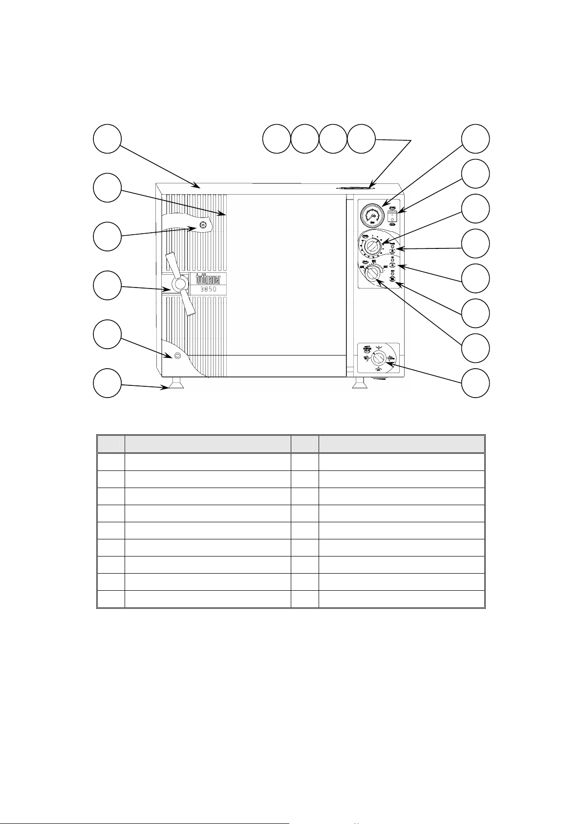
FRONT VIEW MODEL 38500/3870 M, MK
18
17
16
15
14
13
1 2 3 4
5
6
7
8
9
10
11
12
No. description No. description
1. Water reservoir cover 10. Heat indicator light
2. Water reservoir 11. Thermostat (B10) knob
3. Safety valve 12. Multipurpose valve
4. Air trap jet 13. Front legs
5. Pressure gauge 14. Reservoir water drain valve
6. Main power switch 15. Door Closing Device
7. Timer 16. Door Micro-switch
8. Power indicator light 17. Door cover
9. Dry indicator light 18. Autoclave cover
8
Page 11
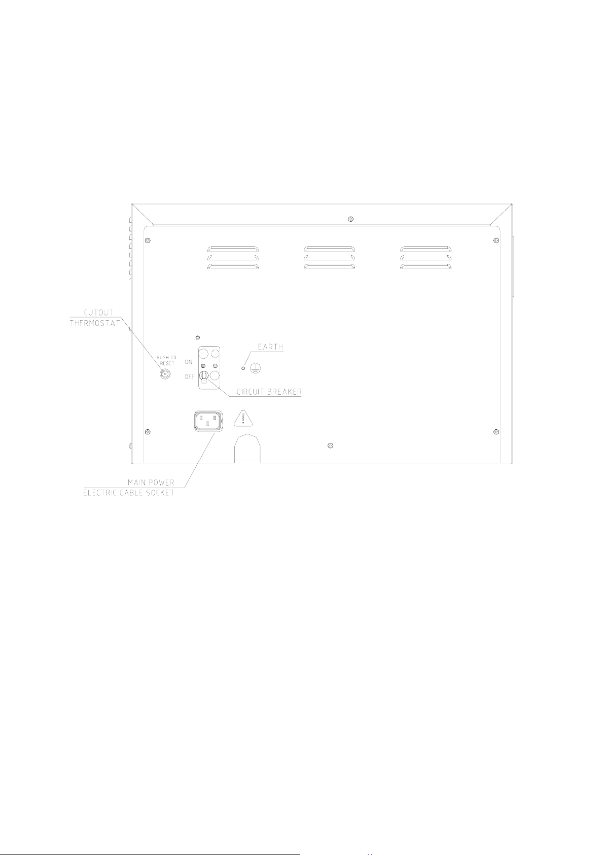
REAR VIEW
9
Page 12

6 MAINTAINING AND REPLACING PARTS
6.1 Safety Tests after Repair
ATTENTION!
After every repair or dismantling the enclosure, the autoclave
should pass two safety electrical test by the Service Engineer. The
following shall be performed:
Warning!
When re-installing the enclosure, connect the earthing to the cover.
On installing the rear cover, connect the earthing before
accomplishing the installation of the rear cover.
6.1.1 Enclosure Leakage Current Test.
Every autoclave should pass this test as follows:
1. Connect the electrical cord to the autoclave.
2. Turn on the main switch and the circuit breaker.
3. Short-circuit the L and N pins on the cord's plug.
4. Connect the Short-circuit pins to the L pole on the Megger.
5. Connect the earth pins to the earth pole on the Megger.
6. Impose an electrical potential of 500-1000V on the tested
autoclave. The insulation resistance should be at least 2
MΩ.
The test is successful if there was no leakage.
6.1.2 Protective Earth Impedance Test
1. Connect the grounding pin of the power cord plug to one
pole of an Ohmmeter.
2. Connect any other metallic part (preferable – the metallic
part of the locking screw) to the second pole of the
Ohmmeter.
3. The resistance should not exceed 0.3 Ω.
After performing these tests, the Service Engineer should complete and
sign the Work Order.
10
Page 13
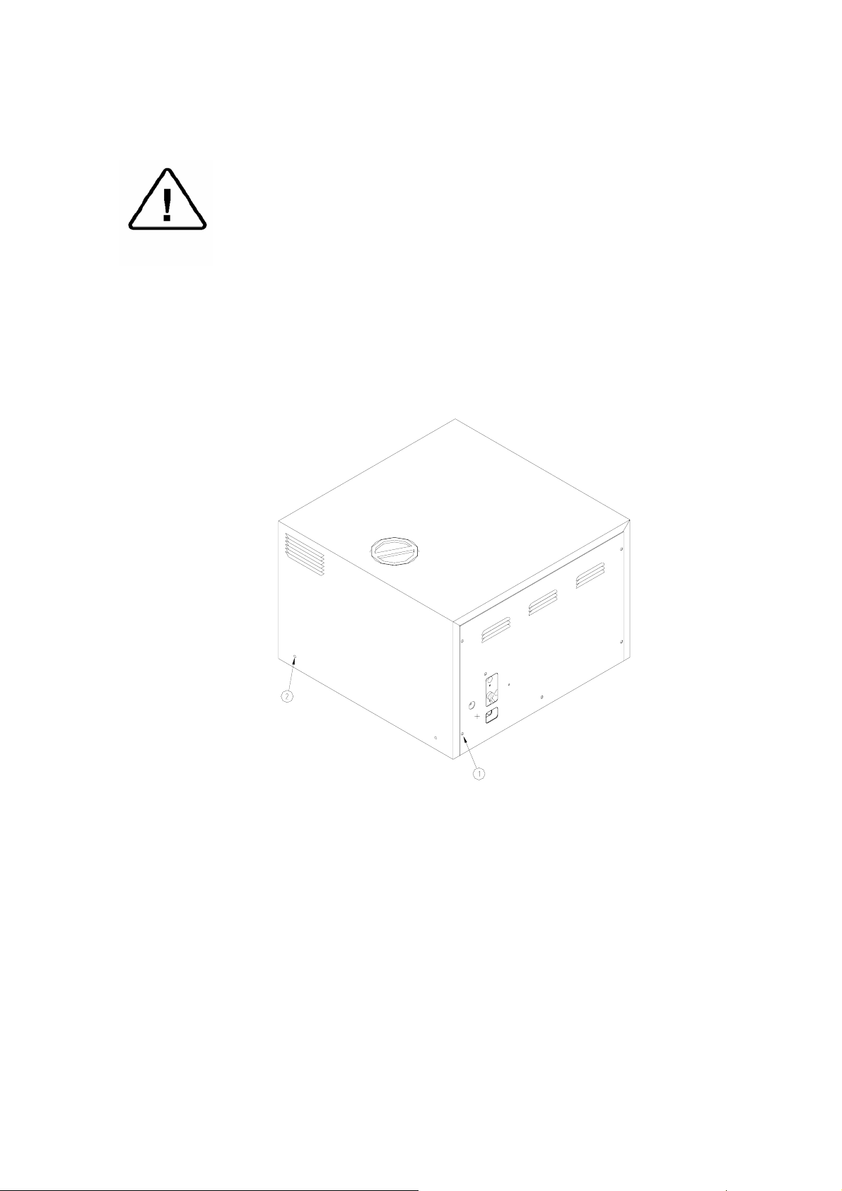
6.2 Dismantling the Outer Cover of the Autoclave.
Caution:
Allow the instrument to cool before removing the outer covers.
Warning:
Before starting disconnect the instrument from the power source
and make sure there is no pressure in the autoclave.
Then proceed as follows:
1. Remove the screws holding the rear cover (1).
2. Remove the screws holding the cover to the base (2).
3. Pull the cover upwards.
11
Page 14
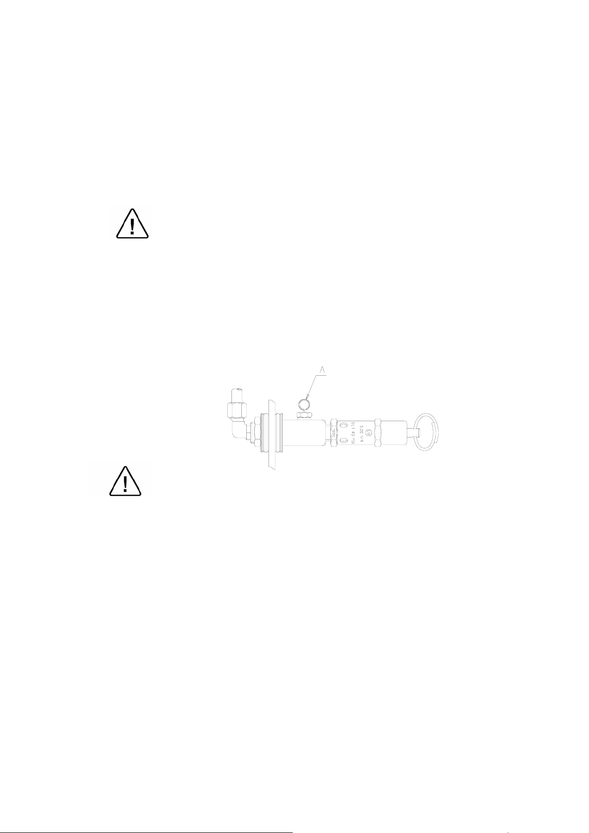
6.3 Cleaning and Replacing Air Trap Jet
(Located in the water reservoir)
The elimination of air pockets from the sterilization chamber during
heating and sterilization phases is achieved by means of the air trap jet.
This device consists of a small orifice that is obtrusive and opened by a
small wire moving forth and back.
The air pockets and small steam quantities are pushed up by the steam
pressure and evacuated through this orifice.
Caution:
Before starting, ensure that the electric cord is disconnected and
that there is no pressure in the autoclave.
1. Remove the water reservoir cover.
2. Clean the hole of the jet by manipulating the air trap wire back and
forth (A).
3. In case it is necessary to replace the air trap jet, allow the
instrument to cool and the pressure to drop to 0 before removing
the jet.
It is important to clean the hole of the air trap, as described at point 2
before starting operation of the autoclave, for the first time.
12
Page 15
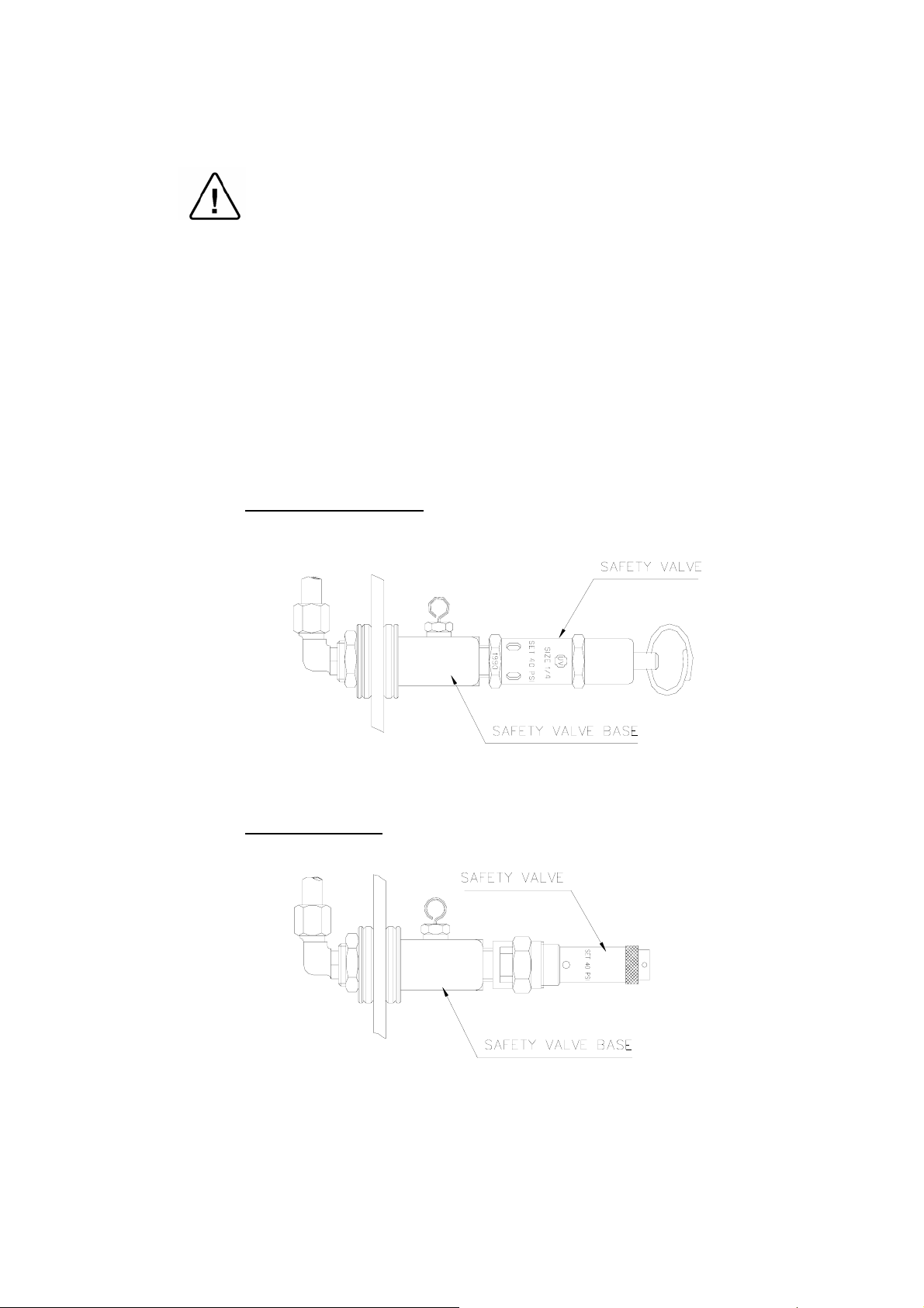
6.4 Replacing the Safety Valve
Caution
Before starting, be sure that the electric cord is disconnected and that
there is no pressure in the autoclave.
Note:
These instructions are valid for both, CE-marked and ASME type
safety valves.
1. Remove the water reservoir cover.
2. Unscrew the safety valve and remove it from the safety valve base.
3. Replace it with a new safety valve (ensure the safety valve is an
original one!)
4. Test all autoclave.
ASME approved Type
CE marked Type
13
Page 16

MK
6.5 Replacing the circuit breaker
Caution!
Before starting, disconnect the instrument from the power source.
1. Remove the autoclave cover (see para. 6.2 “Dismantling the Outer
Covers of the Autoclave”).
2. Disconnect the wires from the circuit breaker.
3. Remove the four screws connecting the circuit breaker to the panel (1).
4. Replace the circuit breaker with a new one.
5. Reconnect the electrical wires.
6. Reassemble the cover.
7. Turn on the autoclave and verify it operates correctly.
8. Move the circuit breaker’s lever to the “tripped” position and verify
that the autoclave turns off.
Make sure that the correct circuit breaker is installed as marked in
the table below!
Model
Voltage
1ph, 120V,
50/60 Hz
1ph, 230V,
50/60 Hz
1730 2340 2540 3140 3850 3870
M
MK
-V
M MK M MK
M
standard special
M M
15 A 15 A 15 A — 15 A — — — — —
10 A 10 A 10 A 15 A 10 A 15 A 10 A 15 A 15 A 15 A
c
Circuit breaker lever
14
Page 17

6.6 Temperature Safety Thermostat
(Located on the rear side of the heaters)
The autoclave is supplied with a temperature thermostat that maintains
the temperature during the dry stage, by connecting and disconnecting
the electric power.
This device automatically disconnects the heating elements in case of a
rise in temperature.
The electric power is automatically reconnected when the chamber
cools down.
♦ To replace this safety thermostat, remove the rear cover, unscrew
the thermostat and replace it.
6.7 Raising the Working the Temperature of the Safety Thermostat
Caution:
Only authorized technician should do this operation!
1. Unscrew the rear cover of the autoclave.
2. With a screwdriver, turn the central screw slightly clockwise to
raise the temperature.
3. Replace the rear cover.
Safety Thermostat
15
Page 18

t
6.8 Cut-Off Thermostat
This thermostat cuts out power to the autoclave, in the event that all
other safety systems do not function. For example: if the operator
forgets to fill the chamber with water, and starts the sterilization cycle,
the chamber will heat up and activate the cut-out thermostat. In order to
restart the operation, press the RESET button. If the autoclave is
operated according to the instructions, and the thermostat cuts off, a
replace the thermostat.
The thermostat has been calibrated by the manufacturer of the
autoclave.
Do not attempt to re-calibrate it
Cut-Off Thermosta
Reset Button
16
Page 19

6.9 Replacing Heating Elements
Caution:
Before starting, ensure that the electric cord is disconnected from the
power source and there is no pressure in the autoclave chamber.
1. Dismantle the autoclave cover (see para. 6.2 “Dismantling the
Outer Covers of the Autoclave”).
2. Release the two terminal wires from the heating element.
3. Remove the heater tightening bolts (1).
4. Replace the damaged heating element with a new one and
reconnect the two terminal wires.
4.1 On the 3140M special model, the front heating element (3)
(adjacent to the chamber's door) is with grooves (4).
Assemble it with the grooves frontward.
5. Re-assemble the autoclave cover.
6. Test all the autoclave cycles.
2
1
Standard Model
2
1
3
4
3140 Special Model
17
Page 20

6.10 Replacing Multi-Purpose Valve
Caution:
Before starting, make sure that the electric cord is disconnected from
the power source and there is no pressure in the autoclave chamber.
1. Dismantle the autoclave cover (see para. 6.2 “Dismantling the
Outer Covers of the Autoclave”).
2. Drain the water from the water reservoir.
3. Pull the valve knob out.
4. Unscrew the 3 nuts that tighten the copper tubes to the multipurpose valve.
5. Unscrew the nut holding the valve to its base.
6. Pull out the valve.
7. Replace it with a new one. Make sure that the valve is tightened to
the valve base.
8. Reconnect the three tube nuts.
9. Return the valve knob to its place.
10. Turn the valve knob to FILL position.
11. Pour water into the reservoir.
12. Check the copper tube connections for leakage.
13. Replace the cover and tighten it to the base.
Occasionally, it is necessary to take off the screws that are on the shaft
of the valve in order to take the valve out of its base.
For Position of Micro-Switches see next page
After installing the new valve, the screws should be replaced according
to drawing "Multi-Purpose Valve Assembly ".
18
Page 21

Position of Micro-Switches and their Operation Situation
M.Sw Stage -0- Fill Ste. Exh. + Dry
M.Sw.1 Tight Tight Loose Loose
M.Sw.2 Loose Loose Loose Tight
M.Sw.3 Loose Loose Loose Tight
Notes:
1. Microswitches MSw1 - STER. and MSw. 2- DRY are actuated by the multipurpose valve.
2. Microswitch MSw3 - Door Sw. is actuated by the door and is in pos. ON when
the door is closed.
19
Page 22

6.11 Unclogging the multi-Purpose Valve or Chamber
VERY IMPORTANT!
When sterilizing cotton wool or pads, it is essential to wrap them in
paper or cotton bags in order to prevent the multi-purpose valve and
the autoclave openings from becoming clogged with remnants of the
material.
1. Pour distilled water into the chamber, according to quantities
mentioned in the table below:
1730 2340/2540 3140 3850 3870
10-12
oz
300-350
ml
12-15
oz
350-450
ml
14-16
oz
420-480
ml
20-23
oz
600-690
ml
24-27
oz
720-810
2. Close the door.
3. Turn the multi-purpose valve to STE. position.
4. Turn the timer knob to 20 min.
5. Turn the thermostat (B10) knob to either 250°F or 274°F° (121°C
to 134°C).
6. Turn the main switch to START position.
7. After the timer has reached “0” turn the multi-purpose valve
(clockwise) to the FILL position.
ml.
In most cases, the pressure pushes the obstructing substance out,
and the steam exhausts into the water reservoir.
8. When the pressure gauge reaches 0, turn the multi-purpose valve
to the OFF position, and the main switch to STOP.
9. Open the door.
10. Replace the water in the water reservoir.
The autoclave is ready for the next cycle.
11. If this procedure does not clear up the clogging, replace the multipurpose valve.
6.12 Pressure Door Lock System
This safety device prevents the door from opening when the chamber is
pressurized.
The system is based on the built up pressure in the chamber that pushes
the Silicon-rubber bellows and the pin into the grove of the tightening
bolt. This prevents the operator from opening the door. When the steam
is released, this bellow returns to its original position, drawing the pin
with it thus releasing the tightening bolt.
Should there be no pressure in the chamber, and the door cannot be
opened, the following procedure should be observed.
1. Turn the handle of the multi-purpose valve to EXH. & DRY.
2. The steam exhaust valve pipe is open and air inserts the chamber.
In this stage the door can be opened.
20
Page 23

6.13 Replacing the Door Bellows
(Located in the Door Bridge)
Caution:
Before starting, be sure that there is no pressure in the autoclave
chamber.
1. Open the door.
2. Unscrew and remove the tightening screw (5).
3. Gently pull out the door safety device locking pin (13).
4. It is possible that the washers (7, 10) will be stuck - if so, push
them out by introducing pressurized air through the steam inlet
hole.
5. Reconnect the door device locking pin (13) into a new silicone
bellows (12).
6. Put the silicone bellows (12) and pin (13) into the bellows housing
(14) and replace the washers (7, 10).
7. Reconnect all the above into the door bridge.
8. Re-screw and tighten the tightening screw (5).
9. Test all autoclave cycles.
LOK240-0026 LOK240-0025
LOK240-0023 GAS080-0020
LOK240-0024
GAS080-0006
21
Page 24

6.14 Replacing the thermostat B10
Caution:
Before starting, be sure that the electric cord is disconnected from the
power source and that there is no pressure in the autoclave chamber.
1. Remove the autoclave cover (see para. 6.2 “Dismantling the Outer
Covers of the Autoclave”).
2. Unscrew the nut (1) connecting the pressure pipe (the pipe
connecting the thermostat to the chamber).
3. Remove the isolating cover.
4. Remove the thermostat knob.
5. Unscrew the 2 screws connecting the thermostat to the panel
(located under the thermostat knob).
6. Unscrew the nuts connecting the wires to the thermostat (2).
7. Remove the thermostat and replace it with a new one.
8. Reconnect the electrical wires.
9. Reassemble the thermostat to the panel.
10. Reassemble the knob and the pressure pipe.
11. Re-assemble the isolating and the autoclave cover.
12. Test and calibrate the pressure switch.
13. Test all the autoclave cycles and verify it operates correctly.
1
2
22
Page 25

6.15 Replacement of the Door Cover
Caution:
Before starting, be sure that the electric cord is disconnected from the
power source and that there is no pressure in the autoclave chamber.
1. Unscrew the four screws attaching the door cover and remove the
door cover. Since the screw pressing the door microswitch
includes two washers and a spring, be aware not to lose them.
2. Reassemble the new cover.
3. Insert screw (1) until dimension A is approximately 15 mm.
3.1 Please note that on model 3140 two washers (2) are placed
between the spring (4) and the door.
4. Perform final adjustment of the screw as follows:
4.1 While the autoclave is disconnected from electricity turn on
the circuit breaker.
4.2 Connect the electrical plug to a multi-meter.
4.3 Press the microswitch and verify that the microswitch
functions as required.
4.4 Close the door and verify that the microswitch operates.
4.5 If the microswitch does not operate unscrew the screw one
turn counter-clockwise and check per para. 4.4. Repeat until
microswitch operates.
4.6 Connect the autoclave to electricity.
4.7 Close the door until the microswitch indicates that the door is
closed. Operate the autoclave and verify that there is no steam
or pressure leak.
4.8 If there is steam leak, stop the autoclave’s operation, reduce
steam pressure, open the door and turn the screw one turn
clockwise and check per para. 4.7. Repeat until leakage
ceases.
5
2
3
4
No. Description Model Cat. No. No. Description Model Cat. No.
2340, 2540 BOL191-0032 3 Washer All models ELE036-0009
1 Screw
1730, 3140
3850, 3870
BOL191-0091 4 Spring All models SPR177-0012
2340, 2540 BOL191-0033 1730 POL065-0001
2 Screw
3140 BOL191-0115 2340, 2540 POL066-0002
1730, 3850,
3870
BOL191-0140
Door
5
cover
3
1
3140 COV314-0001
3850, 3870 POL065-0004
23
Page 26

6.16 Replacing the Locking Device
Caution:
Before starting, verify that there is no pressure in the autoclave
chamber.
1. Remove the security ring (9) using a special tool.
2. Remove pin (6).
3. Remove locking device. Take care not to lose the Teflon disk (10).
4. Reassemble the new locking device.
5. Insert the pin (6).
6. Reassemble the security ring (9).
CLOSING DEVICE
No. Description No. Description
1 Bushing 6 Door locking device pin
Door tightening bolt
2
assembly
3 Locking screw housing 8 Closing bridge “c” clip
4 Locking base 9 Cotter pin
5 Locking housing axis 10 Teflon disk
24
7 Bakelite handle
Page 27

6.17 Replacing the Door Switch (models 2540, 3150, 3850, 3870)
Caution!
Before starting, disconnect the instrument from the power source and
ensure that there is no pressure in the autoclave.
Allow the autoclave to cool before removing outer covers.
1. Remove the autoclave cover (see para. 6.2 “Dismantling the Outer
Covers of the Autoclave”).
2. Disconnect the wires (1), (2) from the door switch (3).
3. Remove the microswitch and replace it with a new one.
4. Reconnect the wires the microswitch. Verify that the wire is placed
on the isolating cover (4) and does not touch the chamber.
5. Reassemble the door cover.
6. Test the connection with an ohmmeter. In “open” position the
ohmmeter shows disconnection and in “close” position the
ohmmeter shows connection.
1
3
2
4
25
Page 28

6.18 Replacing the Drain Valve
Caution!
Before starting, disconnect the instrument from the power source and
ensure that there is no pressure in the autoclave.
Allow the autoclave to cool before removing outer covers.
1. Remove the autoclave cover (see para. 6.2 “Dismantling the Outer
Covers of the Autoclave”).
2. Disconnect the drainpipe from the valve, using a 9/16” wrench.
3. Remove the nut (3) and the “ring for drain valve” (2).
4. Remove the drain valve (1) from the panel.
5. Install a new valve according to the drawing below.
6. Verify that there is no leakage.
CMT240-0020 CMT240-0003 VLV170-0066
Item Cat No.
1 GAS082-0020
2 GAS082-0021
26
Page 29

Corrections
until the main switch.
electrical problem.
1.1 Follow instructions in para. 6.10.
1.2 Follow instructions in para. 6.10.
2.1 Check and replace it if necessary.
2.2 Replace “POWER” bulb.
2.3 Check and repair the line from the entry
2.4 Replace the “Power” light.
2.5 Check out the unit for an internal
Possible cause check-up and tests
purpose valve to “DRY” position.
If “HEAT” & “DRY” lights are on then
“POWER” bulb is burnt.
then the electrical line is faulty.
“Exh/Dry” position and set the timer to 15
minutes.
is burned out. When finished turn the timer
back to 0 minutes
1.1 Multi-purpose valve of chamber is clogged.
1.2 The pipe is clogged.
2.1 Main Switch is defective.
2.2 Set timer for 15 minutes. Turn the multi-
2.3 If also “HEAT” & “DRY” lights are not on
2.4 Turn the multi-purpose valve to the
If the “Dry” light is on then the “Power” light
2.5 The “Dry” light does not come on.
Symptom
FILL position.
7 TROUBLESHOOTING
1. Multi-purpose valve is in
the chamber.
Water does not enter into
START position, power is
supplied, C.B. in ON
position, POWER
indicator light does not
light up.
2. While main switch is in
27
Page 30

Corrections
Possible cause check-up and tests
3.1.1 Replace faulty bulb.
3.2.1 Adjust the thermostat (B10).
3.2.2 Replace the faulty Microswitch.
3.2.3 Fix the bridge.
3.3.1 Fix or replace the faulty thermostat (B10).
3.3.2 Fix or replace the faulty thermostat.
3.3.3 Fix or replace the faulty timer.
3.3.4 Fix or replace the faulty microswitch.
3.3.5 Fix or replace the faulty thermostat (B10).
release. If leakage continues, replace it.
3.3.6 Fix or replace the faulty door switch.
4.1 Calibrate the thermostat (B10).
4.2 Pull safety valve ring for 2 seconds, then
4.3 Replace the air trap jet.
persists, replace door seal.
4.4 Tighten door locking bolt. If leakage
connection.
4.5 Locate leakage and repair faulty piping
3.1.1 Burnt bulb.
Symptom
STE. position, main
switch in ON position.
Timer and thermostat
(B10) are in any working
3. Multi-purpose valve is in
3.2.1 Thermostat (B10) set to too low temperature
3.2.2 Microswitch No.2 is faulty.
3.2.3 Bridge No. 10 is faulty.
3.3.1 Thermostat (B10) is faulty.
on but the autoclave
operates.
position and the door is
closed tightly.
3.1 “HEAT” light is not
3.2 “HEAT” light is not
3.3.2 Safety thermostat faulty.
3.3.3 Timer is faulty.
3.3.4 Microswitch No.3 is faulty.
3.3.5 Thermostat (B10) is faulty.
on and heating is
insufficient.
on and there is no
heating.
3.3 “HEAT” light is not
28
3.3.6 Door switch is faulty.
4.1 Thermostat (B10) is not calibrated.
4.2 Steam escapes from safety valve.
4.3 Air trap jet hole leaks excessively.
4.4 Steam escapes from the door seal.
STE. position. POWER
and HEAT indicator lights
are lit. and water level is
as specified
4. Multi-purpose valve on
are not sufficient.
Temperature and pressure
4.5 Steam escapes from piping connections.
Page 31

Corrections
5.1 Check and replace heaters if necessary.
5.2 Check if chamber holds the correct
Possible cause check-up and tests
amount of water (see para. 6.11).
replace gasket.
bellows.
& Maintenance Manual". If leaking
persists replace the Safety valve.
5.3 Tighten a bit more, if leakage continues,
5.4 Calibrate the thermostat.
5.5 Door bellows is leaking. Replace the
5.6 Activate the safety valve (see "Operation
(stops heating in the “increase pressure” stage).
temperature.
6.1 Set the thermostat to the right
6.2 Replace the valve (see para. 6.10).
temperature.
to water reservoir.
6.3 Replace the safety valve (see para. 6.4).
6.4 Replace air jet (see para. 6.3)
7.1 Fix or replace the thermostat (B10).
7.2 Replace the Pressure safety valve.
when reaching required temp.
5.1 One or more heaters are burnt.
5.2 Too much water in the chamber.
5.3 Door gasket leakage.
5.4 Safety thermostat is not set to the right temp
Symptom
slowly.
5. Pressure builds up very
5.5 Steam is leaking at the closing device
5.6 Safety Valve is leaking
29
6.1 The thermostat is not set to the right
6. Temperature safety device
6.2 Multi-purpose valve is leaking. Water returns
is activated during the ste.
cycles due to overheating
6.3 Safety valve is leaking.
6.4 Air trap jet leaks excessively.
and water amount is
sufficient.
7.1 Faulty thermostat (B10) does not stop heating
position. Pressure safety
7. Autoclave in STE.
7.2 Pressure safety valve is faulty.
valve is activated and
heating continues.
Page 32

Corrections
8.1 Replace the “Dry” light.
Possible cause check-up and tests
(clockwise), then attempt to open.
9.1 Slightly turn handle in closing direction
Door Lock System”. After opening the
door, replace the bellows.
9.2 If problem persists, refer to “Pressure
damaged.
bellows.
10.1 Door bellows is leaking. Replace the
& Maintenance Manual". If leaking
persists replace the Safety valve.
10.2 Activate the safety valve (see "Operation
11.1 Replace the multi-purpose valve.
12.1 Replace the multi-purpose valve.
has broken.
13.1 Replace the timer.
purpose valve binding.
14.1 Replace the timer.
8.1 The “Dry” light is burned out.
Symptom
not light up at the
beginning of the dry cycle.
The Power light is on and
the unit does heat up.
8. Dry indicator light does
9.1 Door pin set in groove.
9.2 Door locking system stuck or bellows
turned counter clockwise
for opening.
9. Door handle cannot be
10.1 Steam is leaking at the closing device.
burning or melting.
10. Items in the chamber are
30
10.2 Safety Valve is leaking.
11.1 The internal spring in the multi-purpose valve
backwards.
11. Multi-purpose valve turns
12.1 Poor maintenance will result in the multi-
12. Multi-purpose valve does
13.1 Internal gearing has worn down.
not turn.
13. Timer does not time down.
14.1 The hammer on the timer bell has broken off.
14. Timer bell does not ring.
Page 33

GENERAL VIEW OF VESSEL, DOOR AND ACCESSORIES
Closing device
Door
Chamber
31
Page 34

AUTOCLAVE COVER
32
Page 35

DOOR TIGHTENING BOLT – ASSEMBLY
Cat. No.
No. Description
1730, 2340, 2540 3140, 3850, 3870
1 Bushing LOK240-0003 LOK387-0003
2 Door tightening bolt assembly LOK240-0036 LOK387-0007
3 Locking screw housing LOK240-0005 LOK387-0006
4 Locking base LOK240-0012 LOK387-0012
5 Locking housing axis LOK240-0014 LOK387-0014
6 Door locking device pin LOK240-0019 LOK387-0016
7 Bakelite handle HAN071-0003 HAN071-0006
8 Closing bridge “c” clip NUT193-0339 NUT193-0300
9 Cotter pin LOK692-0039 LOK692-0039
10 Okolon disc LOK240-0017 LOK387-0017
Bushing (1) + Locking screw housing (3) +
Closing bridge “c” clip (8)
LOK240-0002 LOK387-0002
Door tightening bolt – assembly LOK240-0001 LOK387-0030
33
Page 36

MULTI-PURPOSE VALVE ASSEMBLY
Model 1730
Models 2340/2540/3140/3850/3870
34
Page 37

8 LIST OF SPARE PARTS
Description
Thermostat, Cut-Off,
TY95-H, Campini
Thermostat, Safety, 180C,
TY95/AC, Campini
Heating Element, 120V,
350W 1730 M/E
Heating Element, 120V,
350W 2340 M/E
Heating Element, 120V,
350W 2540 M/E
Heating Element, 230V,
350W, 1730 M/E
Heating Element, 230V,
350W, 2340 M/E
Heating Element, 230V,
350W, 2540 M/E
Heating Element, 120V,
450W, 1730 MK/EK
Heating Element, 230V,
450W, 1730 MK/EK
Heating Element, 230V,
550W, 2340 MK/EK
Heating Element, 230V,
550W, 2540 MK/EK
Heating Element 230V
600W 3140 M/E
Heating Element
230V 800W 3140
M/E, w/o groove
Heating Element
230V 800W 3140
Special Model
M/E, with groove
Heating Element, 230V,
600W, 3850 M/E
Heating Element, 230V,
500W, 3870 M/E
Heating Element, 240V,
350W, 1730 M/E
Heating Element, 240V,
350W, 2340 M/E
Heating Element, 240V,
350W, 2540 M/E
Heating Element, 240V,
450W, 1730 MK/EK
Heating Element, 240V,
550W, 2340 MK/EK
Heating Element, 240V,
550W, 2540 MK/EK
Cat. No.
1730 2340 2540 3140 3850 3870
THE005-0014 THE005-0014 THE005-0014 THE005-0014 THE005-0014 THE005-0014
THE005-0003 THE005-0003 THE005-0003 THE005-0003 THE005-0003 THE005-0003
HEA009-0001 —— —— —— —— ——
—— HEA009-0002 —— —— —— ——
—— —— HEA009-0003 —— —— ——
HEA009-0004 —— —— —— —— ——
—— HEA009-0005 —— —— —— ——
—— —— HEA009-0006 —— —— ——
HEA010-0007 —— —— —— —— ——
HEA010-0008 —— —— —— —— ——
—— HEA010-0003 —— —— —— ——
—— —— HEA010-0004 —— —— ——
—— —— —— HEA009-0014 —— ——
—— —— —— HEA009-0015 —— ——
—— —— —— HEA009-0016 —— ——
—— —— —— —— HEA009-0007 ——
—— —— —— —— —— HEA009-0008
HEA009-0009 —— —— —— —— ——
—— HEA009-0010 —— —— —— ——
—— —— HEA009-0011 —— —— ——
HEA010-0010 —— —— —— —— ——
—— HEA010-0005 —— —— —— ——
—— —— HEA010-0006 —— —— ——
35
Page 38

Description
Heating Element, 240V,
800W, 3850 M/E
Heating Element, 240V,
600W, 3870 M/E
Circuit Breaker, 1PH,
10A, Carlingswitch
Circuit Breaker, Rail,
1PH, 15A, Carlingswitch
Circuit Breaker, 1-PH,
25A, Carlingswitch
Timer, Mechanical,
0-60 min, Faucigny
Switch, Rocker, 16A
Microswitch, E13-00M,
15A, 125/250VAC,
3/4HP, Cheery
Microswitch, E11-00-H,
Cheery
Lamp, Orange, 110V,
8mm
Lamp, Orange, 230V,
8mm
Lamp, Green, 110V, 8mm
Cat. No.
1730 2340 2540 3140 3850 3870
—— —— —— —— HEA009-0012 ——
—— —— —— —— —— HEA009-0013
ELE035-0069 ELE035-0069 ELE035-0069 ELE035-0069 — —
ELE035-0021 ELE035-0021 ELE035-0021 ELE035-0021 ELE035-0021 ELE035-0021
— — — ELE035-0060 — —
ELE033-0001 ELE033-0001 ELE033-0001 ELE033-0001 ELE033-0001 ELE033-0001
ELE035-0012 ELE035-0012 ELE035-0012 ELE035-0012 ELE035-0012 ELE035-0012
ELE036-0001 ELE036-0001 ELE036-0001 ELE036-0001 ELE036-0001 ELE036-0001
ELE036-0002 ELE036-0002 ELE036-0002 ELE036-0002 ELE036-0002 ELE036-0002
ELE038-0003 ELE038-0003 ELE038-0003 ELE038-0003 ELE038-0003 ELE038-0003
ELE038-0006 ELE038-0006 ELE038-0006 ELE038-0006 ELE038-0006 ELE038-0006
ELE038-0002 ELE038-0002 ELE038-0002 ELE038-0002 ELE038-0002 ELE038-0002
Lamp, Green, 230V, 8mm
Gauge, Pressure, Steam,
0-60 psi, Red Pointer
Gauge, Pressure, Steam,
0-60 psi, 1.5"
Handle, Door, Bakelite
for TTA (522)
Knob, Timer
Knob, Thermostat (B10)
M
Cover, Door
MK
Dipstick, Reservoir,
Water, Superp.
Cover, Reservoir, Water,
Superp.
Bellows, Door Lock
Gasket, Door
Disc, Silicone, Door
Bellows
Gasket, Silicone, Water
Reservoir
Cable, Plug+Socket
230V 10A, EUR
ELE038-0005 ELE038-0005 ELE038-0005 ELE038-0005 ELE038-0005 ELE038-0005
— GAU029-0005 GAU029-0005 GAU029-0005 GAU029-0005 GAU029-0005
GAU029-0008 — — — — —
HAN071-0003 HAN071-0003 HAN071-0003 HAN071-0006 HAN071-0006 HAN071-0006
HAN071-0011 HAN071-0011 HAN071-0011 HAN071-0011 HAN071-0011 HAN071-0011
HAN071-0012 HAN071-0012 HAN071-0012 HAN071-0012 HAN071-0012 HAN071-0012
POL065-0001
POL067-0005 POL067-0005 POL067-0005 POL067-0005 POL067-0005 POL067-0005
POL067-0004 POL067-0004 POL067-0004 POL067-0004 POL067-0004 POL067-0004
GAS080-0020 GAS080-0020 GAS080-0020 GAS080-0020 GAS080-0020 GAS080-0020
GAS080-0021 GAS080-0002 GAS080-0003 GAS080-0029 GAS080-0004 GAS080-0004
GAS080-0006 GAS080-0006 GAS080-0006 GAS080-0006 GAS080-0006 GAS080-0006
GAS080-0007 GAS080-0007 GAS080-0007 GAS080-0007 GAS080-0007 GAS080-0007
WIR040-0003 WIR040-0003 WIR040-0003 WIR040-0003 WIR040-0003 WIR040-0003
POL065-0032 POL065-0033
COV314-0001 POL065-0003 POL065-0003
POL065-0031 POL065-0029
36
Page 39

Description
Cable, Plug+Socket 110V
15A, USA
Cable, Plug+Socket
220V 15A, USA
Multi-purpose valve assy.
complete with harness
Multi-purpose valve with
M.Sw.
Valve, Multipurpose,
Assembly+Base
Valve, Multi-Purpose
Cat. No.
1730 2340 2540 3140 3850 3870
WIR040-0004 WIR040-0004 WIR040-0004 WIR040-0004 WIR040-0004 WIR040-0004
WIR040-0005 WIR040-0005 WIR040-0005 WIR040-0005 WIR040-0005 WIR040-0005
CMT173-0006 CMT240-0028 CMT240-0028 CMT314-0006 CMT385-0005 CMT387-0027
CMT173-0026 CMT240-0046 CMT240-0046 CMT240-0046 CMT240-0046 CMT240-0046
CMT173-0027 CMT240-0016 CMT240-0016 CMT240-0016 CMT240-0016 CMT240-0016
VLV170-0067 VLV170-0065 VLV170-0065 VLV170-0065 VLV170-0065 VLV170-0065
Harness, Electrical,
Valve, Multipurpose
CE marked
Safety
valve
Air Jet, MK/EK, Red
Air Jet, M/E, Black
Socket for electric cord,
15A
Socket for electric cord,
10A
Leg, Front, TTA
Leg, Front, Long, TTA
Leg, Rubber, Plug Type,
25x1/4
Reservoir, Water,
Assembly
Cover, Outer
Rear cover
1/4 x 2.8 Bar
ASME
1/4"-40 psi
ELC173-0002 ELE032-0001 ELE032-0001 ELC314-0005 ELC385-0006 ELC387-0015
SVL029-0028 SVL029-0028 SVL029-0028 SVL029-0028 SVL029-0028 SVL029-0028
SVL029-0004 SVL029-0004 SVL029-0004 SVL029-0004 SVL029-0004 SVL029-0004
CMT100-0003 CMT100-0003 CMT100-0003 CMT100-0003 CMT100-0003 CMT100-0003
CMT100-0006 CMT100-0006 CMT100-0006 CMT100-0006 CMT100-0006 CMT100-0006
WIR040-0016 WIR040-0016 WIR040-0016 — — —
WIR040-0003 WIR040-0003 WIR040-0003 — — —
WHE070-0012 WHE070-0012 WHE070-0012 — — —
— — — WHE070-0013 WHE070-0013 WHE070-0013
WHE070-0016 WHE070-0016 WHE070-0016 WHE070-0016 WHE070-0016 WHE070-0016
CMT173-0025 CMT240-0025 CMT240-0025 CMT240-0025 CMT387-0024 CMT387-0024
COV173-0002 COV240-0002 COV240-0002 COV314-0002 COV385-0002 COV387-0002
RCV173-0002 RCV240-0002 RCV240-0002 RCV314-0001 RCV387-0005 RCV387-0005
Drain valve
Brass spacer for drain
valve
Nut for drain valve
O-Ring (drain valve)
10 x 2.5
O-Ring (drain valve)
6 x 2
Autoclave vessel
Door Assembly
Cooling coil
Bushing for selector
valve
VLV170-0066 VLV170-0066 VLV170-0066 VLV170-0066 VLV170-0066 VLV170-0066
CMT240-0003 CMT240-0003 CMT240-0003 CMT240-0003 CMT240-0003 CMT240-0003
CMT240-0020 CMT240-0020 CMT240-0020 CMT240-0020 CMT240-0020 CMT240-0020
GAS082-0020 GAS082-0020 GAS082-0020 GAS082-0020 GAS082-0020 GAS082-0020
GAS082-0021 GAS082-0021 GAS082-0021 GAS082-0021 GAS082-0021 GAS082-0021
ASM173-0001 ASM234-0001 ASM254-0001 CHM314-0000 ASM385-0001 ASM387-0001
DOR173-1000 DOR234-1000 DOR254-0000 DOR314-0000 DOR387-0001 DOR387-0001
PIP254-0041 PIP254-0041 PIP254-0041 PIP254-0041 PIP387-0068 PIP387-0068
CMT240-0019 CMT240-0019 CMT240-0019 CMT240-0019 CMT240-0019 CMT240-0019
37
Page 40

Description
Cat. No.
1730 2340 2540 3140 3850 3870
Microswitch D48X
Bellows housing bolt
Safety membrane
housing
Bellows pin
Inner bushing for bellow
Thermostat, B10, Robert
Show
Upper
Control panel
Lower
ELE036-0012 ELE036-0012 ELE036-0012 ELE036-0012 ELE036-0012 ELE036-0012
LOK240-0026 LOK240-0026 LOK240-0026 LOK240-0026 LOK240-0026 LOK240-0026
LOK240-0025 LOK240-0025 LOK240-0025 LOK240-0025 LOK240-0025 LOK240-0025
L0K240-0023 L0K240-0023 L0K240-0023 L0K240-0023 L0K240-0023 L0K240-0023
CMT067-0002 CMT067-0002 CMT067-0002 CMT067-0002 CMT067-0002 CMT067-0002
THE005-0002 THE005-0002 THE005-0002 THE005-0002 THE005-0002 THE005-0002
CPN064-0023 CPN064-0023 CPN064-0023
CPN064-0025 CPN064-0022 CPN064-0022
CPN064-0024 CPN064-0024 CPN064-0024
38
Page 41

9 PRESSURE VS TEMPERATURE FOR SATURATED STEAM
°C kPa Bar °F psig psia °C kPa Bar °F InHg psia
104.3 117.9 1.18 219.7 2.4 17.1 45.8 10 0.10 114.5 2.95 1.5
104.4 118.6 1.18 219.9 2.5 17.2 54.1 15 0.15 129.3 4.44 2.2
104.5 118.6 1.19 220.1 2.5 17.2 60.1 20 0.20 140.2 5.90 2.9
104.6 119.3 1.19 220.3 2.6 17.3 65.0 25 0.25 149.1 7.39 3.6
104.7 120.0 1.20 220.5 2.7 17.4 68.9 30 0.30 156.4 8.86 4.4
104.8 120.0 1.20 220.6 2.7 17.4 72.7 35 0.35 162.9 10.34 5.1
104.9 120.4 1.20 220.8 2.8 17.5 75.9 40 0.40 168.6 11.81 5.8
105.0 120.7 1.21 221.0 2.8 17.5 78.8 45 0.45 173.8 13.30 6.5
105.1 121.3 1.21 221.2 2.9 17.6 81.3 50 0.50 178.4 14.76 7.3
105.2 122.0 1.22 221.4 3.0 17.7
°C kPa Bar °F psig psia
105.3 122.0 1.22 221.5 3.0 17.7
105.4 122.7 1.23 221.7 3.1 17.8 100.0101.3 1.01 212.0 0.0 14.7
105.5 122.7 1.23 221.9 3.1 17.8 100.1101.7 1.02 212.2 0.1 14.8
105.6 123.4 1.23 222.1 3.2 17.9 100.2102.1 1.02 212.4 0.1 14.8
105.7 124.1 1.24 222.3 3.3 18.0 100.3102.4 1.02 212.5 0.2 14.9
105.8 124.1 1.24 222.4 3.3 18.0 100.4102.8 1.03 212.7 0.2 14.9
105.9 124.7 1.24 222.6 3.4 18.1 100.5103.2 1.03 212.9 0.3 15.0
106.0 125.1 1.25 222.8 3.5 18.2 100.6103.6 1.04 213.1 0.3 15.0
106.1 125.5 1.26 223.0 3.5 18.2 100.7104.0 1.04 213.3 0.4 15.1
106.2 126.0 1.26 223.2 3.6 18.3 100.8104.3 1.04 213.4 0.4 15.1
106.3 126.2 1.26 223.3 3.6 18.3 100.9104.7 1.05 213.6 0.5 15.2
106.4 126.8 1.27 223.5 3.7 18.4 101.0105.1 1.05 213.8 0.5 15.2
106.5 127.2 1.27 223.7 3.8 18.5 101.1105.4 1.05 214.0 0.6 15.3
106.6 127.7 1.28 223.9 3.8 18.5 101.2105.8 1.06 214.2 0.7 15.4
106.7 128.1 1.28 224.1 3.9 18.6 101.3106.2 1.06 214.3 0.7 15.4
106.8 128.5 1.29 224.2 3.9 18.6 101.4106.6 1.07 214.5 0.8 15.5
106.9 129.0 1.29 224.4 4.0 18.7 101.5106.9 1.07 214.7 0.8 15.5
107.0 129.6 1.29 224.6 4.1 18.8 101.6107.3 1.07 214.9 0.9 15.6
107.1 129.9 1.30 224.8 4.2 18.9 101.7107.7 1.08 215.1 0.9 15.6
107.2 130.4 1.30 225.0 4.2 18.9 101.8108.1 1.08 215.2 1.0 15.7
107.3 130.8 1.31 225.1 4.3 19.0 101.9108.4 1.08 215.4 1.0 15.7
107.4 131.3 1.31 225.3 4.3 19.0 102.0108.8 1.09 215.6 1.1 15.8
107.5 131.7 1.32 225.5 4.4 19.1 102.1109.2 1.09 215.8 1.1 15.8
107.6 132.2 1.32 225.7 4.5 19.2 102.2109.6 1.10 216.0 1.2 15.9
107.7 132.6 1.33 225.9 4.6 19.3 102.4110.0 1.10 216.3 1.3 16.0
107.8 133.1 1.33 226.0 4.6 19.3 102.5110.7 1.11 216.5 1.4 16.1
107.9 133.5 1.34 226.2 4.7 19.4 102.6111.1 1.11 216.7 1.4 16.1
108.0 134.0 1.34 226.4 4.7 19.4 102.7111.5 1.12 216.9 1.5 16.2
108.1 134.4 1.34 226.6 4.8 19.5 102.8111.9 1.12 217.0 1.5 16.2
108.2 134.9 1.35 226.8 4.9 19.6 102.9112.3 1.12 217.2 1.6 16.3
108.3 135.3 1.35 226.9 4.9 19.6 103.0112.7 1.13 217.4 1.7 16.4
108.4 135.8 1.36 227.1 5.0 19.7 103.1113.1 1.13 217.6 1.7 16.4
108.5 136.2 1.36 227.3 5.1 19.8 103.2113.5 1.14 217.8 1.8 16.5
108.6 136.7 1.37 227.5 5.1 19.8 103.3114.0 1.14 217.9 1.8 16.5
108.7 137.1 1.37 227.7 5.2 19.9 103.4114.3 1.14 218.1 1.9 16.6
108.8 137.6 1.38 227.8 5.2 19.9 103.5114.7 1.15 218.3 1.9 16.6
108.9 138.1 1.38 228.0 5.3 20.0 103.6115.1 1.15 218.5 2.0 16.7
109.0 138.5 1.39 228.2 5.4 20.1 103.7115.6 1.16 218.7 2.1 16.8
109.1 139.0 1.39 228.4 5.5 20.2 103.8116.0 1.16 218.8 2.1 16.8
109.2 139.5 1.39 228.6 5.6 20.3 103.9116.3 1.16 219.0 2.2 16.9
109.3 140.0 1.40 228.7 5.6 20.3 104.0116.7 1.17 219.2 2.2 16.9
109.4 140.5 1.40 228.9 5.7 20.4 104.1117.1 1.17 219.4 2.3 17.0
109.5 140.9 1.41 229.1 5.7 20.4 104.2117.5 1.18 219.6 2.4 17.1
39
Page 42

°C kPa Bar °F psig psia °C kPa Bar °F psig psia
115.1 169.7 1.70 239.2 9.9 24.6 109.6141.4 1.41 229.3 5.8 20.5
115.2 170.2 1.70 239.4 10.0 24.7 109.7142.0 1.42 229.5 5.9 20.6
115.3 170.8 1.71 239.5 10.0 24.7 109.8142.4 1.42 229.6 5.9 20.6
115.4 171.3 1.71 239.7 10.1 24.8 109.9142.9 1.43 229.8 6.0 20.7
115.5 171.8 1.72 239.9 10.2 24.9 110.0143.3 1.43 230.0 6.1 20.8
115.6 172.4 1.72 240.1 10.3 25.0 110.1143.9 1.44 230.2 6.2 20.9
115.7 173.1 1.73 240.3 10.4 25.1 110.2144.3 1.44 230.4 6.3 21.0
115.8 173.6 1.74 240.4 10.5 25.2 110.3144.8 1.45 230.5 6.3 21.0
115.9 174.1 1.74 240.6 10.6 25.3 110.4145.3 1.45 230.7 6.4 21.1
116.0 174.7 1.75 240.8 10.6 25.3 110.5145.8 1.46 230.9 6.4 21.1
116.1 175.3 1.75 241.0 10.7 25.4 110.6146.2 1.46 231.1 6.5 21.2
116.2 175.9 1.76 241.2 10.8 25.5 110.7146.7 1.47 231.3 6.6 21.3
116.3 176.4 1.76 241.3 10.9 25.6 110.8147.2 1.47 231.4 6.6 21.3
116.4 177.0 1.77 241.5 11.0 25.7 110.9147.7 1.48 231.6 6.7 21.4
116.5 177.6 1.78 241.7 11.1 25.8 111.0148.2 1.48 231.8 6.8 21.5
116.6 178.2 1.78 241.9 11.2 25.9 111.1148.6 1.49 232.0 6.9 21.6
116.7 178.7 1.79 242.1 11.2 25.9 111.2149.6 1.49 232.2 7.0 21.7
116.8 179.3 1.79 242.2 11.3 26.0 111.3149.6 1.50 232.3 7.0 21.7
116.9 180.0 1.80 242.4 11.4 26.1 111.4150.3 1.50 232.5 7.1 21.8
117.0 180.5 1.80 242.6 11.5 26.2 111.5151.0 1.51 232.7 7.2 21.9
117.1 181.1 1.81 242.8 11.6 26.3 111.6151.0 1.51 232.9 7.2 21.9
117.2 181.6 1.82 243.0 11.7 26.4 111.7151.7 1.52 233.1 7.3 22.0
117.3 182.2 1.82 243.1 11.7 26.4 111.8152.2 1.52 233.2 7.4 22.1
117.4 182.8 1.83 243.3 11.8 26.5 111.9152.7 1.53 233.4 7.4 22.1
117.5 183.4 1.83 243.5 11.9 26.6 112.0153.2 1.53 233.6 7.5 22.2
117.6 184.0 1.84 243.7 12.0 26.7 112.1153.8 1.54 233.8 7.6 22.3
117.7 184.5 1.85 243.9 12.1 26.8 112.2154.3 1.54 234.0 7.7 22.4
117.8 185.1 1.85 244.0 12.1 26.8 112.3154.8 1.55 234.1 7.7 22.4
117.9 185.7 1.86 244.2 12.2 26.9 112.4155.3 1.55 234.3 7.8 22.5
118.0 186.3 1.86 244.4 12.3 27.0 112.5155.8 1.56 234.5 7.9 22.6
118.1 186.9 1.87 244.6 12.4 27.1 112.6156.3 1.56 234.7 8.0 22.7
118.2 187.5 1.88 244.8 12.5 27.2 112.7156.8 1.57 234.9 8.1 22.8
118.3 188.2 1.88 244.9 12.6 27.3 112.8157.3 1.57 235.0 8.1 22.8
118.4 188.8 1.89 245.1 12.7 27.4 112.9157.9 1.58 235.2 8.2 22.9
118.5 189.4 1.89 245.3 12.8 27.5 113.0158.4 1.58 235.4 8.3 23.0
118.6 190.0 1.90 245.5 12.9 27.6 113.1158.9 1.59 235.6 8.4 23.1
118.7 190.6 1.91 245.7 13.0 27.7 113.2159.4 1.59 235.8 8.4 23.1
118.8 191.2 1.91 245.8 13.0 27.7 113.3159.9 1.60 235.9 8.5 23.2
118.9 191.8 1.92 246.0 13.1 27.8 113.4160.4 1.60 236.1 8.6 23.3
119.0 192.4 1.92 246.2 13.2 27.9 113.5160.0 1.61 236.3 8.7 23.4
119.1 193.0 1.93 246.4 13.3 28.0 113.6161.5 1.62 236.5 8.7 23.4
119.2 193.7 1.94 246.6 13.4 28.1 113.7162.1 1.62 236.7 8.8 23.5
119.3 194.3 1.94 246.7 13.5 28.2 113.8162.6 1.63 236.8 8.9 23.6
119.4 194.9 1.95 246.9 13.6 28.3 113.9163.1 1.63 237.0 9.0 23.7
119.5 195.5 1.95 247.1 13.7 28.4 114.0163.7 1.64 237.2 9.0 23.7
119.6 196.1 1.96 247.3 13.8 28.5 114.1164.2 1.64 237.4 9.1 23.8
119.7 196.7 1.97 247.5 13.9 28.6 114.2164.8 1.65 237.6 9.2 23.9
119.8 197.3 1.97 247.6 13.9 28.6 114.3165.3 1.65 237.7 9.3 24.0
119.9 197.9 1.98 247.8 14.0 28.7 114.4165.9 1.66 237.9 9.4 24.1
120.0 198.5 1.99 248.0 14.1 28.8 114.5166.4 1.66 238.1 9.4 24.1
120.1 199.2 1.99 248.2 14.2 28.9 114.6167.0 1.67 238.3 9.5 24.2
120.2 199.8 2.00 248.4 14.3 29.0 114.7167.5 1.67 238.5 9.6 24.3
120.3 200.5 2.00 248.5 14.4 29.1 114.8168.0 1.68 238.6 9.7 24.4
120.4 201.1 2.01 248.7 14.5 29.2 114.9168.6 1.69 238.8 9.7 24.4
120.5 201.8 2.02 248.9 14.6 29.3 115.0169.1 1.69 239.0 9.8 24.5
40
Page 43

°C kPa Bar °F psig psia °C kPa Bar °F psig psia
125.9 238.7 2.39 258.6 19.9 34.6 120.6202.4 2.02 249.1 14.7 29.4
126.0 239.4 2.39 258.8 20.0 34.7 120.7203.1 2.03 249.3 14.8 29.5
126.1 240.2 2.40 259.0 20.1 34.8 120.8203.7 2.04 249.4 14.8 29.5
126.2 240.9 2.41 259.2 20.2 34.9 120.9204.4 2.04 249.6 14.9 29.6
126.3 241.6 2.42 259.3 20.3 35.0 121.0205.0 2.05 249.8 15.0 29.7
126.4 242.3 2.42 259.5 20.4 35.1 121.1205.7 2.06 250.0 15.3 29.8
126.5 243.1 2.43 259.7 20.6 35.3 121.2206.3 2.06 250.2 15.4 29.9
126.6 243.8 2.44 259.9 20.7 35.4 121.3207.0 2.07 250.3 15.5 30.0
126.7 244.5 2.45 260.1 20.8 35.5 121.4207.6 2.08 250.5 15.6 30.1
126.8 245.3 2.45 260.2 20.9 35.6 121.5208.3 2.08 250.7 15.6 30.3
126.9 246.0 2.46 260.4 21.0 35.7 121.6208.9 2.09 250.9 15.8 30.5
127.0 246.8 2.47 260.6 21.1 35.8 121.7209.6 2.10 251.1 15.8 30.5
127.1 247.6 2.48 260.8 21.2 35.9 121.8210.2 2.10 251.2 15.9 30.6
127.2 248.3 2.48 261.0 21.3 36.0 121.9210.8 2.11 251.4 16.0 30.7
127.3 249.1 2.49 261.1 21.4 36.1 122.0211.5 2.11 251.6 16.1 30.8
127.4 249.9 2.50 261.3 21.5 36.2 122.1212.1 2.12 251.8 16.3 31.0
127.5 250.6 2.51 261.5 21.8 36.5 122.2212.8 2.13 252.0 16.3 31.0
127.6 251.4 2.51 261.7 21.8 36.5 122.3213.5 2.13 252.1 16.4 31.1
127.7 252.2 2.52 261.9 21.9 36.6 122.4214.2 2.14 252.3 16.5 31.2
127.8 252.9 2.53 262.0 22.0 36.7 122.5214.8 2.15 252.5 16.6 31.3
127.9 253.7 2.54 262.2 22.1 36.8 122.6215.2 2.16 252.7 16.7 31.4
128.0 254.5 2.54 262.4 22.2 36.9 122.7216.2 2.16 252.9 16.8 31.5
128.1 255.2 2.55 262.6 22.3 37.0 122.8216.9 2.17 253.0 16.9 31.6
128.2 256.0 2.56 262.8 22.4 37.1 122.9217.6 2.18 253.2 17.0 31.7
128.3 256.8 2.57 262.9 22.5 37.2 123.0218.3 2.18 253.4 17.1 31.8
128.4 257.5 2.58 263.1 22.7 37.4 123.1218.9 2.19 253.6 17.1 31.8
128.5 258.3 2.58 263.3 22.8 37.5 123.2219.6 2.20 253.8 17.2 31.9
128.6 259.1 2.59 263.5 22.9 37.6 123.3220.3 2.20 253.9 17.3 32.0
128.7 259.8 2.60 263.7 23.0 37.7 123.4221.0 2.21 254.1 17.4 32.1
128.8 260.6 2.61 263.8 23.1 37.8 123.5221.7 2.22 254.3 17.5 32.2
128.9 261.4 2.61 264.0 23.2 37.9 123.6222.4 2.22 254.5 17.6 32.3
129.0 262.2 2.62 264.2 23.3 38.0 123.7223.1 2.23 254.7 17.7 32.4
129.1 263.0 2.63 264.4 23.4 38.1 123.8223.7 2.24 254.8 17.8 32.5
129.2 263.8 2.64 264.6 23.6 38.3 123.9224.4 2.24 255.0 17.9 32.6
129.3 264.6 2.65 264.7 23.7 38.4 124.0225.1 2.25 255.2 17.9 32.6
129.4 265.4 2.65 264.9 23.8 38.5 124.1225.8 2.26 255.4 18.0 32.7
129.5 266.2 2.66 265.1 23.9 38.6 124.2226.5 2.26 255.6 18.1 32.8
129.6 267.0 2.67 265.3 24.0 38.7 124.3227.2 2.27 255.7 18.2 32.9
129.7 267.8 2.68 265.5 24.1 38.8 124.4227.9 2.28 255.9 18.3 33.0
129.8 268.6 2.69 265.6 24.3 39.0 124.5228.6 2.29 256.1 18.4 33.1
129.9 269.4 2.69 265.8 24.4 39.1 124.6229.3 2.29 256.3 18.6 33.3
130.0 270.3 2.70 266.0 24.5 39.2 124.7230.0 2.30 256.5 18.7 33.4
130.1 271.1 2.71 266.2 24.6 39.3 124.8230.7 2.31 256.6 18.8 33.5
130.2 271.9 2.72 266.4 24.7 39.4 124.9231.5 2.31 256.8 18.9 33.6
130.3 272.7 2.73 266.5 24.8 39.5 125.0232.2 2.32 257.0 19.0 33.7
130.4 273.5 2.73 266.7 25.0 39.7 125.1232.9 2.33 257.2 19.1 33.8
130.5 274.3 2.74 266.9 25.1 39.8 125.2233.6 2.34 257.4 19.2 33.9
130.6 275.1 2.75 267.1 25.2 39.9 125.3234.4 2.34 257.5 19.3 34.0
130.7 275.9 2.76 267.3 25.3 40.0 125.4235.1 2.35 257.7 19.4 34.1
130.8 276.7 2.77 267.4 25.4 40.1 125.5235.8 2.36 257.9 19.5 34.2
130.9 277.5 2.78 267.6 25.6 40.3 125.6236.5 2.37 258.1 19.6 34.3
131.0 278.3 2.78 267.8 25.7 40.4 125.7237.3 2.37 258.3 19.7 34.4
131.1 279.1 2.79 268.0 25.8 40.5 125.8238.0 2.38 258.4 19.8 34.5
41
Page 44

Legend:
psia ─ absolute pressure in psi
Psig ─ gauge pressure in psi
kPa ─ absolute pressure in kilo-Pascal
InHg ─ pressure (vacuum) in inch-Mercury
°C kPa Bar °F psig psia °C kPa Bar °F psig psia
135.2 315.0 3.15 275.4 31.2 45.7 131.2280.0 2.80 268.2 25.9 40.6
135.3 315.9 3.16 275.5 31.3 45.8 131.3280.9 2.81 268.3 26.0 40.7
135.4 316.8 3.17 275.7 31.5 45.9 131.4281.7 2.82 268.5 26.2 40.9
135.5 317.7 3.18 275.9 31.6 46.1 131.5282.6 2.83 268.7 26.3 41.0
135.6 318.6 3.19 276.1 31.7 46.2 131.6283.4 2.83 268.9 26.4 41.1
135.7 319.5 3.20 276.2 31.9 46.3 131.7284.3 2.84 269.1 26.5 41.2
135.8 320.5 3.20 276.4 32.0 46.5 131.8285.1 2.85 269.2 26.7 41.4
135.9 321.4 3.21 276.6 32.1 46.6 131.9286.0 2.86 269.4 26.8 41.5
136.0 322.4 3.22 276.8 32.3 46.8 132.0286.8 2.87 269.6 26.9 41.6
136.1 323.3 3.23 277.0 32.4 46.9 132.1287.7 2.88 269.8 27.0 41.7
136.2 324.3 3.24 277.2 32.6 47.0 132.2288.5 2.89 270.0 27.1 41.8
136.3 325.2 3.25 277.3 32.7 47.2 132.3289.4 2.89 270.1 27.3 42.0
136.4 326.2 3.26 277.5 32.8 47.3 132.4290.2 2.90 270.3 27.4 42.1
136.5 327.1 3.27 277.7 33.0 47.4 132.5291.1 2.91 270.5 27.5 42.2
136.6 328.1 3.28 277.9 33.1 47.6 132.6291.9 2.92 270.7 27.6 42.3
136.7 329.0 3.29 278.1 33.2 47.7 132.7292.8 2.93 270.9 27.8 42.5
136.8 330.0 3.30 278.2 33.3 47.9 132.8293.6 2.94 271.0 27.9 42.6
136.9 330.9 3.31 278.4 33.3 48.0 132.9294.5 2.94 271.2 28.0 42.7
137.0 331.9 3.32 278.6 33.4 48.1 133.0295.4 2.95 271.4 28.1 42.8
137.1 332.8 3.33 278.8 33.6 48.3 133.1296.2 2.96 271.6 28.3 43.0
137.2 333.8 3.34 279.0 33.7 48.4 133.2297.1 2.97 271.8 28.4 43.1
137.3 334.7 3.35 279.1 33.8 48.5 133.3297.9 2.98 271.9 28.5 43.2
137.4 335.6 3.36 279.3 34.0 48.7 133.4298.8 2.99 272.1 28.6 43.3
137.5 336.6 3.37 279.5 34.1 48.8 133.5299.7 3.00 272.3 28.8 43.5
137.6 337.5 3.38 279.7 34.3 49.0 133.6300.6 3.01 272.5 28.9 43.6
137.7 338.5 3.38 279.9 34.4 49.1 133.7301.5 3.01 272.7 29.0 43.7
137.8 339.4 3.39 280.0 34.5 49.2 133.8302.4 3.02 272.8 29.2 43.9
137.9 340.4 3.40 280.2 34.7 49.4 133.9303.3 3.03 273.0 29.3 44.0
138.0 341.4 3.41 280.4 34.8 49.5 134.0304.2 3.04 273.2 29.4 44.1
138.1 342.4 3.42 280.6 35.0 49.7 134.1305.1 3.05 273.4 29.5 44.2
138.2 343.4 3.43 280.8 35.1 49.8 134.2306.0 3.06 273.6 29.7 44.4
138.3 344.4 3.44 280.9 35.2 49.9 134.3306.9 3.07 273.7 29.8 44.5
138.4 345.4 3.45 281.1 35.4 50.1 134.4307.8 3.08 273.9 29.9 44.6
138.5 346.4 3.46 281.3 35.5 50.2 134.5308.7 3.09 274.1 30.1 44.8
138.6 347.4 3.47 281.5 35.7 50.4 134.6309.6 310 274.3 30.2 44.9
138.7 348.4 3.48 281.7 35.9 50.6 134.7310.5 3.10 274.5 30.3 45.0
138.8 349.4 3.49 281.8 36.0 50.7 134.8311.4 3.11 274.6 30.5 45.2
138.9 350.4 3.50 282.0 36.1 50.8 134.9312.3 3.12 274.8 30.6 45.3
139.0 351.4 3.51 282.2 36.3 51.0 135.0313.2 3.13 275.0 30.7 45.4
139.1 352.4 3.52 282.4 36.4 51.1 135.1314.1 3.14 275.2 31.1 45.6
42
Page 45

DRAWING OF ELECTRICAL SYSTEM OF TABLE AUTOCLAVE MODELS 1730M, MK
43
Page 46

DRAWING OF ELECTRICAL SYSTEM OF TABLE AUTOCLAVE MODELS 2340/2540 M, MK
44
Page 47

DRAWING OF ELECTRIC SYSTEM OF TABLE AUTOCLAVE MODEL 3140 M
45
Page 48

DRAWING OF ELECTRIC SYSTEM OF TABLE AUTOCLAVE MODELS 3850 M
46
Page 49

DRAWING OF ELECTRICAL SYSTEM OF TABLE AUTOCLAVE MODELS 3870 M
47
Page 50

PIPING DIAGRAM TABLE TOP AUTOCLAVE MODELS: M AND MK
48
 Loading...