

Page 1
LEVELING THE STERILIZER
1.The sterilizer must be placed on a level surface. Note:
When positioning the sterilizer on the surface, be sure
to keep the back and right side of the sterilizer a
pproximately 1" (25mm) away from the wall to allow for
proper ventilation.
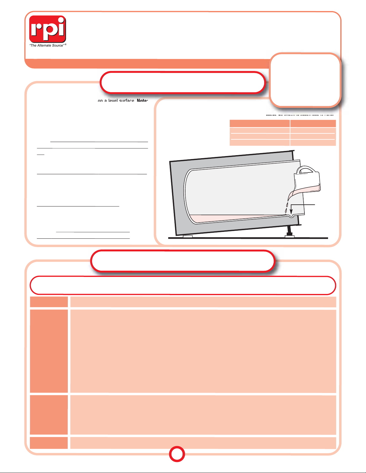
2.T o check if the sterilizer is level: Refer to Table A, to the
right; measure only the amount of water indicated in
the chart for the corresponding model into a measuring
cup
; and, pour the measured water into the chamber.
The water must reach the indication groove near the
front of the chamber. Refer to Figure 1, to the right.
If the water does not reach
or
it goes past the groove
,
the sterilizer is not level and must be
adjusted. To help level the sterilizer, the front legs of the
sterilizer may be adjusted using a wrench.
FILLING THE RESERVOIR
1.Use distilled water only to fill the reservoir
. Fill the reservoir until the water level is 1" (25mm) below the base of
the Safety Valve Holder. Refer to the Min/Max lines on the
Reservoir Dip Stick.
Caution!
For proper operation of the sterilizer,
do
not fill water above the Safety Valve Holder.
YOUR GUIDE TO MAINTAINING TUTTNAUER
™
M/MK SERIES & VALUEKLAVE MKV STERILIZERS
LEVELING & FILLING PROCESS
All product names used in this document are trademarks or registered trademarks of their respective holders.
©RPI, 2012 (REV B 09/12)
The parts mentioned in this document are manufactured by Replacement Parts Industries, Inc. to fit Tuttnauer equipment.
PLANNED MAINTENANCE
FIGURE 1
LEVELING THE STERILIZER
To verify that the sterilizer is
level, the amount of water (as
indicated in Table A, to the
right) when poured into the
chamber must reach the indication groove inside the chamber.
DAILY
WEEKLY
MONTHLY
ANNUALLY
Clean the Door Gasket with a soft cloth or sponge using a soft liquid detergent and water. Rinse well and leave no residue.
Recommended parts to be replaced at this time include the Door Gasket, Chamber Filters, Door Bellows, and parts showing wear.
• During a sterilization cycle, use an insulated tool or pair of needle nose pliers to pull on the end ring of the Safety V alve , and let the
steam exhaust for a couple of seconds. This will remove debris in the lines and clean the valve's orifices. Verify its closing ability.
Caution: During this procedure, be prepared for a rush of steam to be released with a loud hissing sound. W ear appropriate
protective hand and eye gear .
•
After Every 20 Cycles -
Clean Sterilizer with Tutt-Clean™ (RPI Part #'s TUC094 &TUC095) in conjunction with the Sterilizers
Cleaning Kit (RPI Part #RPK791) to help remove water deposits, oxides and other sediments.
• 1. Remove the Trays and Tray Holder from the unit. Clean the Chamber, Tray Holder and Trays with a cloth or sponge using an
OEM recommended cleaner.
Caution: Do not use steel wool, a steel brush or chlorinated cleansers on these parts.
2. Thoroughly rinse Chamber, Tray Holder, and Trays with clean water. Flush the Chamber. Flush the Fill hole located at the back
of the Chamber by turning the Fill Knob to the FILL position for a couple of seconds.
3. Dry the Chamber, Tray Holder and Trays, and reinstall.
• Place a couple of drops of oil on the two door pins and the door tightening bolts.
•Clean the outside of the unit with a soft cloth or sponge using a non-abrasive cleaner.
• Drain and flush the Water Reservoir while using a baby bottle brush to clear any build up of debris. Refill the reservoir (see
FILLING THE RESERVOIR
, above).
• When the sterilizer is cold and not pressurized, verify the integrity of the Spring and Plunger Assembly by pulling and releasing
the end ring on the Safety Valve – it should spring back.
• Remove and clean Chamber Filters.
• Check and clean the Air Jet Valve by moving the wire back and forth several times to prevent debris buildup.
CAUTION!
Before starting any maintenance or repairs:
1) Turn the sterilizer OFF. 2) Unplug the po wer cord from the wall outlet. 3) Verify
that there is no pressure in the unit. 4) Allow to cool to room temperature. 5) Wear appropriate protective hand and eye gear.
Replacement Parts Industries, Inc. is pleased to present this valuable work tool that can help save you and your
customers time and money. Take a look, you will find Troubleshooting Guides, diagrams, exploded views and a
complete listing of all RPI parts that fit all 1730/2340/2540/3870 M/MK and Valueklave
™
1730 MKV Tuttnauer models. It’s
all here, in one easy-to-use tool. Keep it close by–in your RPI catalog or at your workbench.
TABLE A
AMOUNT OF WATER NEEDED, TO CHECK IF STERILIZER IS LEVEL.
Model Amount of Water
1730 Series & Valueklave 1730 MKV 10 - 12 oz. (300 - 355 ML)
2340 & 2540 Series 12 - 15 oz. (355 - 444 ML)
3870 Series 24 - 27 oz. (710 - 798 ML)
INDICATION
GROOVE
1
PLEASE NOTE!
Over the years, Tuttnauer
has substituted parts from
what has been noted in their
manuals. As a precaution,
please verify parts before
replacing or servicing them.
Page 2
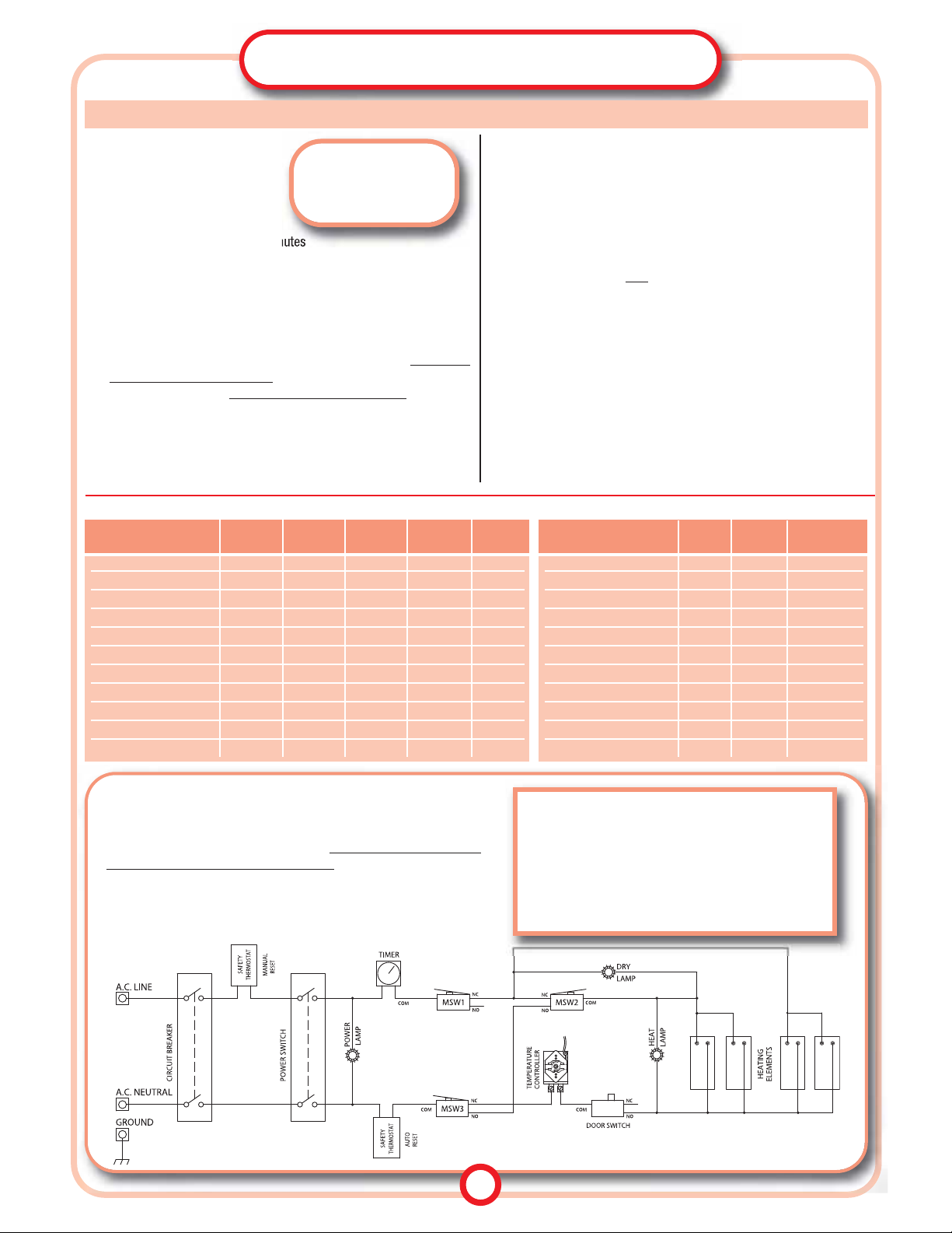
TABLE C
-
APPROXIMATE HEATER ELEMENT RESISTANCE VALUES (±10%)
ELECTRICAL TROUBLESHOOTING
& WIRING DIAGRAMS
BASIC CIRCUIT INSPECTION
1. Disconnect power to unit.
2. Set sterilizer controls to the
following settings:
• Circuit Breaker = ON
• Power Switch = ON
• Sterilizer Door = CLOSED
• Timer = Set for more than 10 minutes
• Temperature Controller = Set at 250º or higher
3. Set a multi-meter to ohm scale, then connect the line and neutral termi-
nals of the power module.
4. Rotate the Multi-Purpose Valve to each setting; starting and ending at O,
and observe the meter for the following:
• In the STE and EXH+DRY positions, the meter should read the circuit
values ( ±10%) shown in Table B, below for each model. If the meter
reads a much higher resistance than shown in Table B, it is an indication of an open circuit. If the reading is significantly lower than shown
in Table B, it is an indication of a short circuit or heater burnout.
• In the O and FILL positions, the meter should read a very high resistance – which indicates an open circuit.
5. Remove unit's covers and insulation blanket. Perform a full visual
inspection of wiring, terminals and connections. Inspect the wiring har-
STE STE EXH-DRY EXH-DRY
Model VAC Amps Ohms Amps Ohms
1730M 120 9.5 13.0 2.0 60
1730M 230 4.8 48.0 1.2 218
1730MK 230 6.0 38.0 1.3 170
1730MKV (Valueklave) 120 13.0 9.0 3.0 40
2340M 120 13.0 9.5 3.2 38
2340M 230 6.5 35.0 1.6 140
2340MK 230 11.5 21.0 2.8 90
2540M 120 13.0 9.0 3.2 38
2540M 230 6.5 35.0 1.6 140
2540MK 230 11.5 9.5 2.8 90
3870M 230 12.0 19.0 3.2 76
Resistance
Model VAC Watts (Ohms)
1730M 120 350 41
1730M 230 350 147
1730MK 230 450 117
1730MKV (Valueklave) 120 450 32
2340M 120 350 41
2340M 230 350 147
2340MK 230 550 96
2540M 120 350 41
2540M 230 350 147
2540MK 230 550 96
3870M 230 1000 112
TABLE B
-
APPROXIMATE CIRCUIT VALUES (±10%) AT STE AND EXH-DRY POSITIONS
FIGURE 2
Schematic of Current Tuttnauer Models 2340M/MK & 2540M/MK
Although the schematic below applies to the current 2340M/MK &
2540M/MK Models of Tuttnauer sterilizers, it can be used as a reference
for all of the other manual models as well. Variations to the wiring of
manual models is common among Tuttnauer sterilizers. For a list of the
variations that might be encountered when servicing these sterilizers,
see the listing to the right.
Variations Between Tuttnauer M/MK/MKV Wiring
• Single vs. Dual Circuit Breakers
• Circuit Breaker(s) or Fuse
• Single or Dual Thermostat
• Wiring of Thermostat (Manual or Automatic reset)
• Wiring of Heat Light or Dry Light
• With or without Door Switch
• Number of Heating Elements required
ness for loose leads and broken or damaged wires. Make any repairs
and retest. If no defects found, then inspect each component and conduct continuity check of the complete wiring circuit.
6. Refer to the schematic in Figure 2, below, check each circuit compo-
nent, starting with the circuit breaker. Take note of the following characteristics for each of the components:
• Safety Thermostats should be closed except at high temperature when
they open to protect the circuit.
Note:
Models built after
January, 1993 have dual
Safety Thermostats, one of which has a
manual reset button and is located near the circuit breaker.
• Timer must be turned
past 10 minutes
to make contact and provide
electrical continuity.
• Control Thermostat must be set above 212˚ F to make contact and
provide electrical continuity.
• Micro-Switch positions and wiring are referenced on page 9, MULTI-
PURPOSE VALVE & MICRO-SWITCHES. (Note: Micro-Switches are
best checked with an analog ohm meter.)
• Heater element resistance values are shown in Table C, below.
7. Repair or replace all faulty circuits or components, then retest unit.
8. Replace insulation blanket and reinstall covers.
9. Run unit for several cycles and check all operations.
SERVICE TIP
When working on the
electrical system, follow
all safety requirements.
2
LEGEND (Located on Multi-Purpose Valve)
MSW1 = Micro-Switch 1 • MSW2 = Micro-Switch 2 • MSW3 = Micro-Switch 3
Page 3
DOOR GASKET & DOOR BELLOWS
Check chamber Door Gasket for any steam leaks, hissing, or water
bubbles at
the Door Bellows. If steam is leaking at the door closing
device, then rotate the Gasket 180˚ to see if the leak follows it. If the
leak follows the Gasket, then replace the Gasket. If the leak does not
follow the Gasket, then replace the Door Bellows.
ISOLATING LEAKS & CORRECTIVE ACTION
HOW TO CHECK THE AIR JET VALVE
Water and steam leaks not only cause damage to the site where the unit is located but also,
will create a low water condition resulting in overheating that could cause major damage to the autoclave.
WATER/STEAM SYSTEM
TROUBLESHOOTING
AIR JET VALVE
Inspect the Air Jet Valve. It should make a slight hissing sound
throughout the STE cycle. If there is excessive hissing, steam, or
water bubbles escaping from the Air Jet Valve, refer to HOW TO
CHECK THE AIR JET VALVE, at the top right hand side of this
page.
Service Tip: Use a dental mirror to help locate the leak.
SAFETY VALVE
Remove the Water Reservoir Fill Cover and visually inspect the Safety
Valve – use a dental mirror to help locate the leak. Confirm that there
is no steam or water drops escaping from the vent holes or threads
of the Safety Valve. If a leakage is observed, replace the Safety Valve.
MULTI-PURPOSE VALVE
Inspect the Multi-Purpose Valve for leakage. Note any leaks at the
three fittings or the valve stem. If none are found, disconnect the
Condensation Coil in the water reservoir at the point where it connects inside the reservoir. Operate the sterilizer in STE mode at
273˚F for 30 minutes on M units
and 15 minutes on MK &
Valueklave 1730 MKV units, and look for any signs of leakage back
into the reservoir from the tubing fitting where the Condensation Coil
was attached. Inspect the water fill tube at the bottom of the reservoir for any signs of steam bubbling back into the reservoir. If any
leakage is noted at either position, repair or replace the MultiPurpose Valve.
Important: Reconnect Condensation Coil before
exhausting Chamber pressure.
CHAMBER & INTERNAL TUBING
Carefully inspect for steam or water bubbles at the Chamber and all
fittings. If a leak is detected at one of the fittings or tubing, tighten
or replace only after the unit has been depressurized and allowed to
cool down.
Visual and audible leaks can be
detected by operating the sterilizer in the normal STE mode with
temperature set at 273º F and the
time set for 30 minutes on M
units and 15 minutes on MK &
Valueklave 1730 MKV units.
Possible points of water/steam
leaks with corrective action, and
order in which they should be checked are noted in #1-5 below.
HOW TO UNCLOG THE MULTI-PURPOSE VALVE DURING A CYCLE
1. Refer to Table A, page 1, and pour the indicated amount of water into
the sterilizer
. Turn the power switch ON.
2. Close and lock the sterilizer door – be sure to make a tight seal and wait
for the heat light to come on.
3. Set the sterilizer to the following settings: Multi-Purpose Valve (MPV) set
to STE position; Timer Knob set to 20 minutes; and, Thermostats Knob to
273˚F (134˚C). Then press power switch to START.
(Note:
With the MPV in
the STE position, heaters will be
ON
, and sterilizer will begin to build pressure.
)
4. When the Chamber pressure reaches 30-31 PSI:
• Turn the Power Switch to the OFF position.
• Turn the MPV to the FILL position. Now the Chamber pressure should
force out debris from the MPV through the Fill Line into the Reservoir.
• When the pressure in the Chamber reaches 0, turn the MPV to the OFF
position, then open the door. Allow the sterilizer to cool.
• Clean out any debris from the inside of the Chamber.
• If the MPV is still clogged, rebuild or replace it.
HOW TO MANUALLY UNCLOG THE MULTI-PURPOSE VALVE
1. Disconnect power from sterilizer. Allow to cool. Remove covers.
2.
At the center port of the Multi-Purpose Valve (MPV), disconnect the fit-
ting. Set MPV to the FILL position.
Service Tip: Drain most of the water
from the Reservoir to prevent excess spillage during this process. This
will also verify that the Drain Tube and Drain Valve are clear.
• If water flows into the Chamber, then the obstruction has been c leared
from MPV and Fill Tube.
•If water does not flow into the Chamber
, check Fill Tube as follows:
Disconnect Fill Tube fitting at bottom of MPV.
- If water flows
, Fill Tube is clear, but MPV must be rebuilt or replaced.
- If water does not flow
, use forced air through Fill Tube and check for
bubbles in Reservoir. If procedure does not clear obstructions, replace
Fill T ube.
Service Tip:When disconnecting Fill Tube, straighten portion
of tube (about 1" lg.) that protrudes into the bottom of Reservoir.
Support Reservoir boss with a wrench.
3. If MPV and Fill Tube are clear, next check Chamber Tube as follows:
Disconnect and remove MPV from Chamber Tube. Use forced air or water
through tube. If procedure does not clear obstructions, replace Chamber
Tube. Also check and clear Chamber Fitting and boss of any obstructions.
4. Check exhaust lines as follows: At the top port of MPV, disconnect
Condensing Coil Tube, see MULTI-PURPOSE VALVE, page 9. Force air
through tube. If the flow is blocked, determine whether Condensing Coil
or Tube is obstructed. Clear obstruction or replace coil and/or tube.
5. If no leaks or obstructions have been found by following the previous
steps, and sterilizer is still experiencing a low water condition resulting in
overheating problems, see HOW TO CHECK THE AIR JET VALVE, above.
1
1
2
2
3
3
4
4
5
5
3
SERVICE TIP
T o help prevent
cl
ogging of the MPV,
install RPI Filters (RPI
Part #MIF062) into
the Water Fill and
Exhaust Lines.
SERVICE TIP
If the Chamber is found to be
defective, tag it as "Out of
Operation". Removal of the
power cord is recommended
until the chamber is replaced.
If a water/steam leak is not related to #1-3 above, disconnect power
from the sterilizer and remove the cover, then carefully remove the insulation blanket. Proceed to #4-5, below.Warning!
Make sure power has
been disconnected prior to removing the cover. When running the sterilizer with the cover removed, the interior of the machine will be very hot
- use extreme caution.
1. Refer to Table A, page 1, and in a
measuring cup, fill it with the amount
of water indicated in the chart for the
corresponding model, then pour the
measured water into the Chamber.
2. Bypass the FILL setting to manually
run sterilizer in STE mode at 273˚F for 30 minutes for M units
and 15
minutes for MK & Valueklave 1730 MKV units. After 30 minutes (or 15
minutes), shut off power , but leave MPV in STE mode until chamber pressure is reduced to 0 PSI and chamber has cooled (approx. 15 minutes).
3. Open Chamber Door, siphon water back into the measuring cup, and
measure the amount of water remaining in the chamber.
- If remaining water is less than 50%
of the original volume and no other
leaks were detected, replace Air Jet Valve.
- If remaining water is greater than 50%
and the pressure did not reach
28 psi within the nominal times (see TABLE D, above), and no
fault
was found within the heating system, then replace the Air Jet Valve.
REMOVING OBSTRUCTIONS
TABLE D
NOMINAL TIMES FOR REACHING 28 PSI
Time from Time from
Model Hot Start Cold Start
M Series 19 min. 24 min.
MK Series & MKV 6 min. 9 min.
Page 4
SYMPTOM CAUSE SOLUTIONS
TROUBLESHOOTING
Power-On Light does not illuminate
Heat Lamp OFF in STE cycle
Heat lamp is ON; No heat or pressure
Wall outlet or plug Verify power at outlet. Make sure power cord
is plugged in at the wall and at the machine.
Power Switch Turn Power Switch ON. Replace if necessary
.
Circuit Breaker
Power Lamp
Reset breaker. Check for short circuit (see page 2). If no short
is found, replace Circuit Breaker
.
Micro-Switch 1 (MSW1) is defective
or it is stuck in the down position.
Check MSW1. Adjust or replace as necessary
.
Timer Check that Timer is turned ON. Timer must be advanced
past 10 minutes to activate.
Control Thermostat Set Control Thermostat to 212˚F or higher
.
Adjust or replace
Control Thermostat as necessary
.
Heat Lamp If unit has heat and pressure, check and/or replace Heat Lamp.
If unit has no
heat, check for open circuit (see page 2).
Replace Power Light.
Open Circuit Check for loose or disconnected wires. Replace Wire Harness,
if necessary.
Heaters Measure Heater for proper resistance, see
Table C, page 2
.
Check for broken/disconnected wiring. Replace if necessary.
Unit overheats, Power and Heat Lights
go out
Low water level
(Over Temp Safety Switch)
Check for water or steam leak. Replace Over Temp Safety
Switch if necessary
.
Heat lamp remains ON when Timer is
at 0 or Timer will not advance
Timer
Timer must be advanced past 10 minutes to activate.
Check Timer operation and replace if necessary
.
Timer Bell does not sound Timer Timer must be advanced past 10 minutes to activate.
Check Timer operation and replace if necessary
.
Water enters Chamber after unit is
exhausted and the door is closed
Condensation Coil Water level is above open end or there is a hole in the
Condensation Coil creating a vacuum. Reduce water level to 1"
below Safety Valve and open end of Condensation Coil must
be above water level. Replace Condensation Coil if necessary.
Multi-Purpose Valve
(if not stuck open)
Remove, disassemble, clean and rebuild, or replace
Multi-Purpose Valve (see MULTI-PURPOSE VALVE, page 9).
Pressure Gauge Check and/or replace Pressure Gauge
.
Heat lamp is ON in STE cycle, but
with low heat and slow pressure
build
Control Thermostat Set Control Thermostat to 212˚F or higher. Adjust or replace
Control Thermostat as necessary
.
Excess water in Chamber Check water level. Check level of unit per
Installation Procedure
,
see
Figure 1, page 1.
Steam Leak Check for audible/visual steam leak at Door Gasket, Door
Bellows, Safety Valve, Air Jet Valve, and Condensation Coil.
If there are air bubbles in reservoir, check Multi-Purpose Valve.
Repair or replace faulty part(s) as necessary.
Heaters Measure Heaters for proper resistance, see
Table C, page 2
.
Check for broken or disconnected wiring.
Safety Valve opens
Safety Valve If Safety Valve opens below rated cracking pressure, replace it
.
Control Thermostat Reset Control Thermostat to proper value or, if necessary,
replace it
.
Unit overheats, Heat Light stays ON Water level
Check for audible/visual steam leak at Door Gasket, Door
Bellows, Safety Valve, Air Jet Valve, and Condensation Coil.
If there are air bubbles in reservoir, check Multi-Purpose Valve.
Repair or replace part(s) as necessary.
Water or steam leak
Check fill operation and water level, see
Figure 1, page 1.
4
Page 5
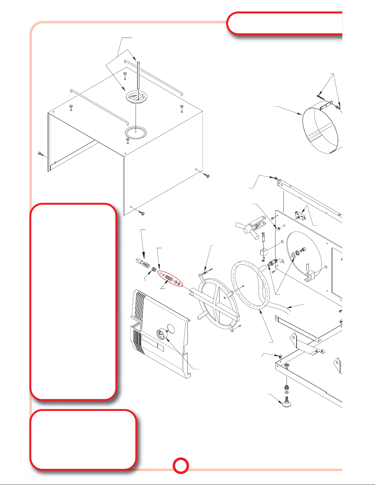
EXPLODED VIEW
FREE TECHNICAL ASSISTANCE
FROM RPI
CALL (800) 221-9723
FAX (818) 882-7028
E-MAIL [email protected]
WEBSITE www.rpiparts.com
HELPFUL TOOLS!
TUT073
TEST-3
TAP (3/8-19 BSPP)
TUG110
TEST-2
PRESSURE GAUGE (TEST)
RPT113
(No OEM Part # Available)
MAX. REGISTER THERMOMETER
CLEANERS
TUC094
CB0010 (CHAMBER BRITE™)
TUTT-CLEAN™
10 packets per box
TUC095
CB0010 (CHAMBER BRITE™)
TUTT-CLEAN™
(1) case - 12 boxes per case
CLEANING KIT
RPK791
(No OEM Part # Available)
CLEANING KIT
TUK075 - RESERVOIR COVER WITH DIPSTICK
TUC067 - WATER RESERVOIR/FILTER COVER
TUS068 - WATER RESERVOIR DIPSTICK
HEATERS
(SEE TABLE E)
TUH015 (X3)
HARDWARE KIT
5
0
10
20
400
239
259
psi/F
Pa
100
200
PRESSURE GAUGES
(SEE TABLE E)
TUB072
TUF058
TUA066
TUB064
RPH285
PCN136
TUS014
PCN136
TUV042
DOOR GASKETS
(SEE TABLE E)
TUB019
DOOR
BELLOWS
TUK030
DOOR BELLOWS
ASSEMBLY KIT
TUT073
TAP
ALIGN PAGE 6 WITH THIS EDGE FOR A COMPLETE "EXPLODED VIEW OF STERILIZER"
Page 6
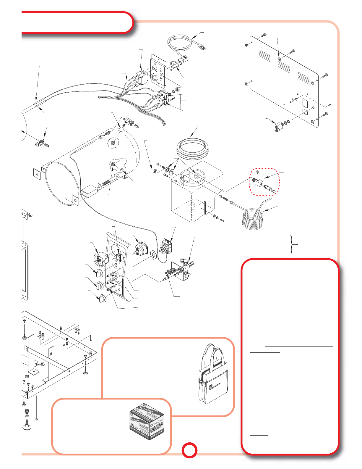
HEATING ELEMENTS SERVICE TIPS
• When replacing a Heater, a burning smell
may be present for several cycles.
This is
normal and does not indicate any malfunction of the new Heater.
• Current Heaters offered by RPI and Tuttnauer are designed to accommodate
Safety Thermostats that use 3/16" diameter bulbs. When replacing the Heater
band that mounts the Safety Thermostats
to the Chamber , take a moment to measure the diameter of the Safety Thermostat
bulbs. If the bulbs are 1/8" diameter
(original style), then replace them with
the newer style 3/16" diameter bulbs to
ensure proper contact to the Chamber
and the Heater band.
• Make sure that the bulb for the automatic
reset Safety Thermostat is installed in the
lower grooveof the Heater band, and that
the bulb for the manual reset thermostat
is installed in the upper groove.
• When installing new Heater bands,
tighten all bolts evenly until the band is
snug against the Chamber. Run the sterilizer through several test cycles and then
retighten
the hardware to ensure proper
fit. Failing to properly tighten Heater
bands can lead to premature failure.
0
10
0
Pa
psi/F
400
239
I
259
20
VENT
PORT
FILL
PORT
MIF062
TUG022
RPR583
TUT038 (MANUAL RESET)
TUT039 (AUTO RESET)
TUK055
TUT007
TUT008
MDL021
MDL019
MDL022
TUS009
TUK049
TUK050
TUK049
PRESSURE
GAUGES
(SEE TABLE E)
TUS035
OVER-TEMP SWITCH
(SEE TABLE E)
WIRE HARNESS
(SEE TABLE E)
CIRCUIT BREAKERS
(SEE TABLE E)
SAFETY THERMOSTATS
(SEE TABLE E)
CONDENSATION COILS
(SEE TABLE E)
SAFETY VALVE AND
SAFETY VALVE HOLDER
(SEE TABLE E)
MICRO-SWITCHES
(SEE PAGE 9)
TUC028
SAFETY THERMOSTAT
(SEE TABLE E)
TUT038 (MANUAL RESET)
TUT039 (AUTO RESET)
SAFETY THERMOSTAT
(SEE TABLE E)
ELBOW
TUF079
FITTING
TUV025 - MULTI-PURPOSE VALVE
(TUV097 & TUV098 NOT SHOWN)
TUK037 - MPV REPAIR KIT
(TUK099 NOT SHOWN)
SEE PAGE 7
“MULTI-PURPOSE
VALVES”
PCN136
CIRCUIT
BREAKERS
(SEE TABLE E)
6
The RPI Sterilizer Cleaning
Kit includes Cleansing Pad,
Sponge, and a wide variety
of sturdy brushes to clean the entire sterilizer from
the chamber to the racks – and it all comes in a
convenient, black canvas carrying case with inside
compartments, and side pockets.
All parts also sold separately including the Convenient Carrying Case.
RPK791
(Entire Kit)
TUC094
(Package of 10 packets)
STERILIZER
CLEANING KIT!
STERILIZER
CLEANING SOLUTION!
TUT-CLEAN™ is a mild acidic salt
cleansing compound formulated for
descaling and removal of water deposits, oxides, and other sediments
from sterilizers. Also available by the
case (RPI Part #TUC095).
ALIGN PAGE 5 WITH THIS EDGE FOR A COMPLETE "EXPLODED VIEW OF STERILIZER"
Page 7
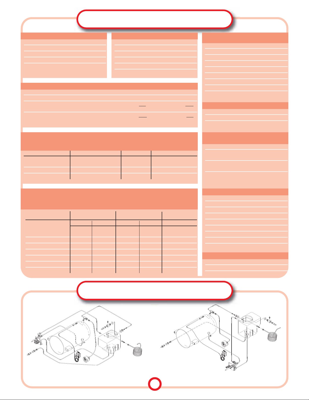
LEFT SIDE MULTI-PURPOSE VALVE MOUNT
UNITS MANUFACTURED BEFORE 1993
RIGHT SIDE MULTI-PURPOSE VALVE MOUNT
UNITS MANUFACTURED AFTER 1993
BASIC PLUMBING CONFIGURATIONS
7
TABLE E - QUICK REFERENCE
RPI Part # Fits Models
TUC040 1730M/MK
TUC041 Fits earlier models where coil joins reservoir at the left rear
and vents towards the front
of the machine.
TUC063 Fits newer models where coil joins reservoir at the left front
and vents towards the rear
of the machine.
RPI Part # Options
TUG020 Smaller sized gauge (1-1/2" dia.)
TUG012 Larger sized gauge (2-1/2" dia.)
PRESSURE GAUGES
RPI Part # Options
TUS035 Over T emperature Switch
(original style)
TUT038 Safety Thermostat
(newer style-manual reset)
TUT039 Safety Thermostat
(newer style-automatic reset)
SAFETY THERMOSTATS &
OVER TEMPERATURE SWITCH
RPI Part # Style Options
TUB023 Lever 15 AMPS
TUB024 Lever 10 AMPS
TUB048 Push Button 7 AMPS
TUB047 Push Button 15 AMPS
CIRCUIT BREAKERS
RPI Part # Fits Models
TUH043 1730M/MK
TUH044 2340M/MK & 2540M/MK
WIRE HARNESSES
RPI Part # Fits Models
TUK121 1730M
TUK122 1730MK & Valueklave 1730 MKV
TUK123 2340M (Serial #8805 and below)
TUK124 2340M (Serial #8806 and above)
TUK126 2340MK
TUK128 2540M
TUK130 2540MK
TUK131 3870M
STERILIZER PM KITS
CONDENSATION COILS
Multi-Purpose Valve Fits Models Description MPV Repair Kit
TUV025 1730M/MK, 2340M/MK, Long Shaft TUK037
2540M/MK & 3870M
TUV097 Valueklave 1730 MKV Long Shaft TUK037
TUV098 Valueklave 1730 MKV Short Shaft TUK099
MULTI-PURPOSE VALVES
NOTE - Valueklaves (1730 MKV) manufactured with the Multi-Purpose V alves on the right side of the machine utilized
either the Long or Short shaft versions.
RPI Part # Fits Models
TUH027 1730M
TUH004 1730MK & Valueklave 1730 MKV
TUH016 1730MK (230VAC)
TUH005 2340M
TUH017 2340MK
TUH006 2540M
TUH018 2540MK
TUH015 Attaching Hardware fits all Models
HEATER ELEMENTS & ATTACHING HARDWARE
(see page 2 for specs)
RPI Part # Fits Models
TUG001 1730M/MK & Valueklave 1730 MKV
TUG002 2340M (Serial #8805 and below)
TUG021 2340M/MK (Serial #8806 and above)
TUG003 2540M/MK
TUG074 3870M
GASKETS
Various Part Options Available for Specific Models.
M MK MKV
Description 1730/2340/2540/3870 1730/2340/2540 Valueklave (1730)
37 PSI 40 PSI 37 PSI 40 PSI 40 PSI
Air Jet Valve TUJ034 TUJ034 TUJ033 TUJ033 TUJ033
Black Top Black Top Red Top Red Top Red Top
Safety Valve Holder Kit TUK054 TUK078 TUK053 TUK077 TUK077
Safety Valve Holder TUH032 TUH032 TUH031 TUH031 TUH031
Safety Valve TUV011 TUV065 TUV011 TUV065 TUV065
Threaded Adapter TUA060 TUA060 TUA060 TUA060 TUA060
Elbow Fitting TUF079 TUF079 TUF079 TUF079 TUF079
Mounting Hardware TUK055 TUK055 TUK055 TUK055 TUK055
SAFETY VALVES & SAFETY VALVE HOLDERS
SERVICE TIP - When a Safety Valve needs replacement, replace it with the same rated PSI Valve – in other words,
replace a 37 PSI valve with a 37 PSI valve, and a 40 with a 40. The PSI cracking pressure is actually etched onto
the body of the Valve for your reference. (See chart below for listing of parts and corresponding Models.)
Page 8
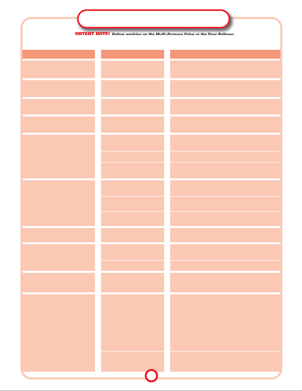
IMPORTANT NOTE!
Before working on the Multi-Purpose Valve or the Door Bellows:
Turn the power OFF. Wear protective hand and eye gear. Use a tool such as a screwdriver or wrench
(do not use your fingers)
to
pull
the Safety Valve Pull Ring, and vent the Chamber to ZERO pressure. Allow the unit to cool down.
SYMPTOM
CAUSE SOLUTION
TROUBLESHOOTING
Multi-Purpose Valve Assembly (MPV)
MPV will not rotate.
MPV valve rotates in both directions.
MPV is jammed. Remove, disassemble, clean and rebuild, or replace MPV.
See Important Note!, above.
Broken Anti-rotational Spring
Clip.
Remove, disassemble, clean and rebuild, or replace MPV.
See Important Note!, above.
MPV will not exhaust in the EXH-DRY
position; Pressure remains high
Clogged MPV, Condensation Coil, or
MPV Tubing.
Remove, disassemble, clean and rebuild, or replace MPV.
See Important Note!, above.
With power ON, MPV in EXH-DRY; Dry
Light is OFF, but unit is drying properly
Dry Light malfunction. Replace Dry Light
.
With power ON, MPV in EXH-DRY; Unit
is not drying properly
Excess water in Chamber. If Chamber door is closed, then open the door 1" to allow for
proper ventilation.
Chamber over packed. Refer to Owners Manual for maximum load.
Heater malfunction. Measure Heater for proper resistance,
see
Table C, page 2
.
Check for broken/disconnected wiring. Replace if necessary.
Door will not open after Chamber is
exhausted and MPV is in the EXH-DRY
position
Door Bellows could be jammed. 1) See Important Note!, above. Then turn door closing device
slightly clockwise to tighten, then turn counter clockwise to
open.
See Important Note!, above. If this does not correct the situa-
tion, then check if MPV has blockage, see
page 3, REMOVING
OBSTRUCTIONS
.
Vacuum in Chamber (pressure
below zero).
2) See Important Note!, above. Remove covers. Carefully move
the Insulation Blanket on the left side to expose the Chamber
Tightening Bolt. Loosen Bolt until Door Locking Assembly is
loose enough to open the Door. After the Door is open, tighten
the Bolt and replace the Insulation Blanket. If necessary,
replace Door Bellows Assembly
.
In EXH-DRY position, Power Light is ON,
Dry Light OFF, but unit is not drying
Timer not activated. Activate Timer by setting it
past 10 minutes
. If timer still does
not activate, then replace Timer.
In EXH-DRY position, Dry and Heat
Lights OFF (Door open)
Micro-Switch 3 (MSW3) is defective
or it is stuck in the up position.
Adjust or replace MSW3. Refer to MULTI-PURPOSE VALVE &
MICRO-SWITCHES, page 9.
In EXH-DRY position, Circuit Breaker
trips when Timer is set.
Micro-Switch 2 (MSW2) is defective
or it is stuck in the up position.
Adjust or replace MSW2. Refer to MULTI-PURPOSE VALVE &
MICRO-SWITCHES, page 9.
With power ON, MPV in EXH-DRY position, all three lights ON (indicating unit
is overheating).
Micro-Switch 3 (MSW3) is defective
or it is stuck in the up position.
Adjust or replace MSW3.
Refer to MULTI-PURPOSE VALVE &
MICRO-SWITCHES, page 9.
Micro-Switch 1 (MSW1) is defective
or it is stuck in the down position.
Set MPV to STE position, if Heat Light is OFF, adjust or replace
MSW1. Refer to MULTI-PURPOSE VALVE & MICRO-SWITCHES, page 9.
Short circuit in Wiring Harness. Check and replace Wiring Harness or repair shorted wire.
Micro-Switch 2 (MSW2) is defective
or it is stuck in the down position.
Set MPV to STE position, if Heat Light is OFF, adjust or replace
MSW2
.
Refer to MULTI-PURPOSE VALVE & MICRO-SWITCHES, page 9.
8
Page 9
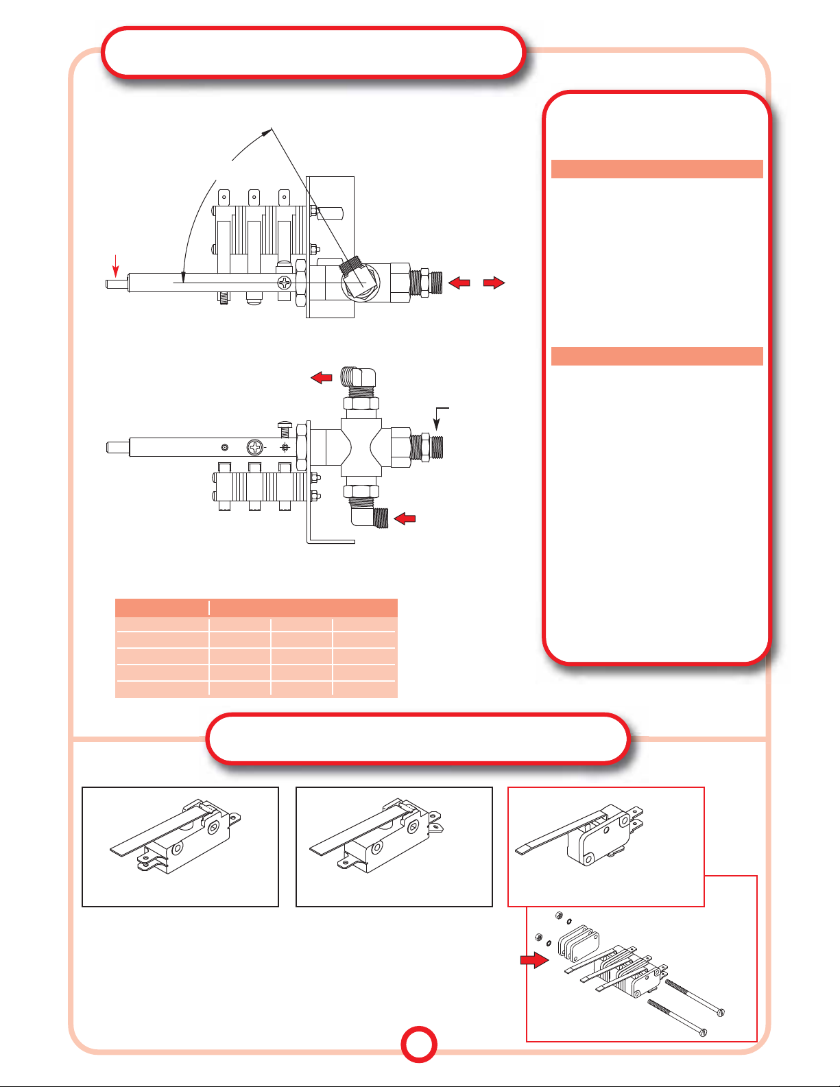
MULTI-PURPOSE VALVE (MPV)
Illustrations shown below refer to right side MPV mount only
MICRO-SWITCHES
SIDE VIEW
TOP VIEW
CONNECTION TO
WATER RESERVOIR (EXHAUST LINE)
POSITION OF VALVE AT
STE (STERILIZE) MODE
FLAT ON SHAFT AT
STE (STERILIZE)
POSITION
MSW3
MSW2
MSW1
CONNECTION TO
THE CHAMBER
MSW1 MSW2 MSW3
0 CLOSED OPEN OPEN
FILL CLOSED OPEN OPEN
STE OPEN OPEN OPEN
EXH-DRY OPEN CLOSED CLOSED
NEW STYLE MICRO-SWITCH OPERATION
CLOSED = SWITCH ACTIVATED • OPEN = SWITCH NOT ACTIVATED
VALVE POSITION SWITCH OPERATION
MOUNTING BRACKET
60˚- 65˚
MICRO-SWITCH (CHERRY E13/BLACK)
RPI PART #TUS013
MICRO-SWITCH (CHERRY E11/GREY)
COM. TAB
COM. TAB
N.C. TAB
N.O. TAB
N.C. TAB
N.O. TAB
SERVICE TIP:
If unit is to be upgraded from the old style Micro-Switches (Cherry E11 or E13)
to the new style Micro-Switch (Cherry D48X/Grey), then the Micro-Switch Kit (RPI Part
#TUK061) must be used. The Kit includes the spacers and hardware that are necessary to
upgrade from the old style to the new style Micro-Switches.
MICRO-SWITCH KIT (NEW STYLE)
RPI PART #TUK061
COM. TAB
N.C. TAB
N.O. TAB
MICRO-SWITCH (CHERRY D48X/GREY)
RPI PART #TUS057
STERILIZATION TIMES
Total Time from Start to Finish
STE Temperature: 273˚F (134˚C)
9
CONNECTION FROM
WATER RESERVOIR
(FILL LINE)
CENTER PORT
M SERIES
CYCLE TYPE: Unwrapped
COLD START: 30 minutes
HOT START: 20 minutes
CYCLE TYPE: Wrapped
COLD START: 40 minutes
HOT START: 30 minutes
CYCLE TYPE: Packs
COLD START: 45 minutes
HOT START: 35 minutes
CYCLE TYPE: Unwrapped
COLD START: 15 minutes
HOT START: 12 minutes
CYCLE TYPE: Wrapped
COLD START: 20 minutes
HOT START: 15 minutes
CYCLE TYPE: Packs
COLD START: 25 minutes
HOT START: 20 minutes
• The sterilization times noted above are
based on the information sticker located on
the unit's outer covering. If the voltage is
significantly less than the voltage noted,
then additional time must be added to each
cycle to ensure proper functionality.
• Tuttnauer sterilizers tend to run a few
degrees higher than the set temperature.
MK SERIES & VALUEKLAVE 1730 MKV
NOTE: The illustrations below show the Multi-Purpose V alve (RPI Part #TUV025). The Multi-Purpose
Valves (RPI Part #'s TUV097 & TUV098) have slightly different connection fittings and orientations
Page 10
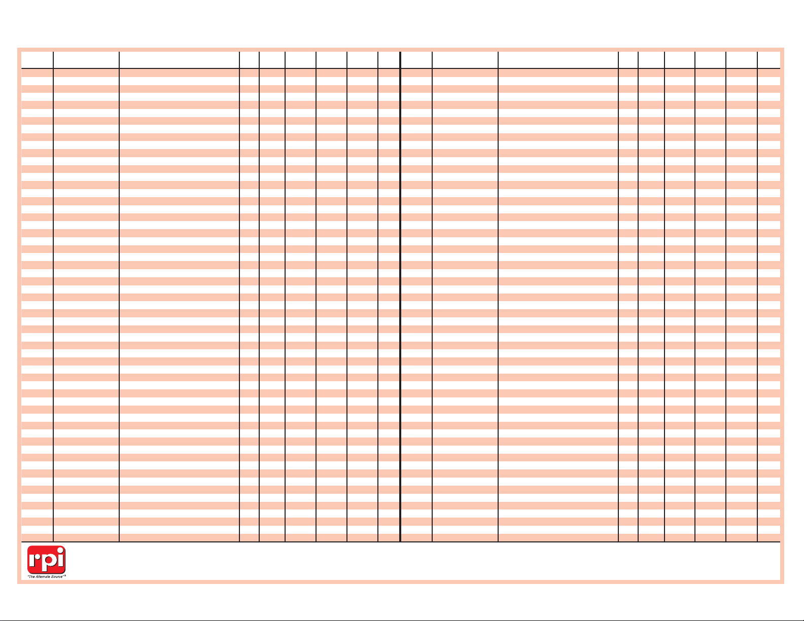
RPI OEM SEE VALUEPART # PART # DESCRIPTION NOTE KLAVE 1730 2340 2540 3870
MDL019 01960007 SIGNAL LIGHT - RED (125VAC) M M M
MDL021 01910257 SIGNAL LIGHT - AMBER (125VAC) MKV M M M
MDL022 01910258 SIGNAL LIGHT - GREEN (125VAC) MKV M M M
MIF062
(No OEM Part # Available)
FILL/VENT MESH CHAMBER FILTER MKV M MK M MK M MK M
PCS036
(No OEM Part # Available)
AIR RELEASE VALVE SEAT MKV M MK M MK M MK M
RPA032
(No OEM Part # Available)
THREADLOCKER 242 MKV M MK M MK M MK M
RPA369
(No OEM Part # Available)
THREADLOCKER 545 MKV M MK M MK M MK M
RPA459
(No OEM Part # Available)
PIPE SEALANT 567 MKV M MK M MK M MK M
RPB792
(No OEM Part # Available)
LARGE DIA. BRUSH (1-3/4") MKV M MK M MK M MK M
RPB793
(No OEM Part # Available)
SMALL DIA. BRUSH (3/8") MKV M MK M MK M MK M
RPB794
(No OEM Part # Available)
SCRUB BRUSH MKV M MK M MK M MK M
RPB795
(No OEM Part # Available)
HANDLE BRUSH MKV M MK M MK M MK M
RPB796
(No OEM Part # Available)
FLEXIBLE TUBE BRUSH (7/8") MKV M MK M MK M MK M
RPC582 02819996 POWER CORD (220VAC) MK MK MK
RPC799
(No OEM Part # Available)
CARRYING CASE MKV M MK M MK M MK M
RPF216
(No OEM Part # Available)
COMPRESSION SLEEVE MKV M MK M MK M MK M
RPF217
(No OEM Part # Available)
COMPRESSION SLEEVE MKV M MK M MK M MK M
RPF221
(No OEM Part # Available)
COMPRESSION NUT MKV M MK M MK M MK M
RPH105
(No OEM Part # Available)
#8 SPLIT LOCK WASHER M MK M MK M MK M
RPH108
(No OEM Part # Available)
#8 FLAT WASHER M MK M MK M MK M
RPH118
(No OEM Part # Available)
METRIC SCREW (M4 X 8) M MK M MK M MK M
RPH130
(No OEM Part # Available)
METRIC SCREW (M4 X 8) MKV M MK M MK M MK M
RPH186
(No OEM Part # Available)
1/4" EXTERNAL TOOTH WASHER MKV M MK M MK M MK M
RPH285 02620016A DRAIN HOSE MKV M MK M MK M MK M
RPK791
(No OEM Part # Available)
CLEANING KIT MKV M MK M MK M MK M
RPL090
(No OEM Part # Available)
HIGH TEMP LUBRICANT MKV M MK M MK M MK M
RPO360
(No OEM Part # Available)
O-RING (Multi-Purpose Valve) MKV M MK M MK M MK M
RPO386 02610030/Inner O-RING (Drain Valve) MKV M MK M MK M MK M
RPO387 02610027/Outer O-RING (Drain Valve) MKV M MK M MK M MK M
RPO439
(No OEM Part # Available)
O-RING (Multi-Purpose Valve) MKV M MK M MK M MK M
RPO448
(No OEM Part # Available)
O-RING (Multi-Purpose Valve) MKV M MK M MK M MK M
RPO488
(No OEM Part # Available)
O-RING (Multi-Purpose Valve) MKV M MK M MK M MK M
RPP798
(No OEM Part # Available)
CLEANSING PAD MKV M MK M MK M MK M
RPR583 02819993 AC INLET RECEPTACLE MKV M M MK M MK M
RPS797
(No OEM Part # Available)
SPONGE (4-1/4" x 6") MKV M MK M MK M MK M
RPT018
(No OEM Part # Available)
WIRE NUT M MK M MK M MK
RPT113
(No OEM Part # Available)
MAX REGISTER THERMOMETER MKV M MK M MK M MK M
RPT579
(No OEM Part # Available)
1/4" TEFLON THREAD SEALING TAPE MKV M MK M MK M MK M
RPT580
(No OEM Part # Available)
1/2" TEFLON THREAD SEALING TAPE MKV M MK M MK M MK M
TUA060
(No OEM Part # Available)
THREADED ADAPTER (Fits Safety Valve Holder) MKV M MK M MK M MK M
TUA066 CT312036 DOOR SWITCH ACTIVATOR MKV M MK M MK M MK M
TUB019
(No OEM Part # Available)
DOOR BELLOWS MKV M MK M MK M MK M
TUB023 01910098 CIRCUIT BREAKER (15A) MKV M M M
TUB024 01910097 CIRCUIT BREAKER (10A) MK
TUB047 01910100 CIRCUIT BREAKER (15A) M MK M MK M MK M
TUB048 01910099 CIRCUIT BREAKER (7A) MK
TUB064 CT245010 DOOR BELLOW HOUSING BOLT MKV M MK M MK M MK M
TUB072
(No OEM Part # Available)
RUBBER BOOT (Fits Door Switch) MKV M MK M MK M MK M
TUC028 02819995 POWER CORD (125VAC) MKV M M M M
TUC040 CU836101 CONDENSATION COIL M MK
TUC041 CT836101 CONDENSATION COIL 1 MKV M MK M MK
TUC063 CT836101 CONDENSATION COIL 1 M MK M MK
TUC067 02550019 WATER RESERVOIR/FILTER COVER MKV M MK M MK M MK M
TUC094 CB0010
(Chamber Brite™)
TUTT-CLEAN™ MKV M MK M MK M MK M
TUC095 CB0010
(Chamber Brite™)
TUTT-CLEAN™ (CASE) MKV M MK M MK M MK M
TUF058 04010001 & 04010002 LEVELING FOOT MKV M MK M MK M MK M
TUF079
(No OEM Part # Available)
ELBOW FITTING (Fits Safety Valve Holder) MKV M MK M MK M MK M
TUG001 02610020 DOOR GASKET MKV M MK
TUG002 02610005 DOOR GASKET 2 M
RPI OEM SEE VALUEPART # PART # DESCRIPTION NOTE KLAVE 1730 2340 2540 3870
TUG003 02610023 DOOR GASKET M MK
TUG012 02300011 PRESSURE GAUGE W/ INDICATOR (2-1/2") M MK M MK M MK M
TUG020 02300012 PRESSURE GAUGE (1-1/2") MKV
TUG021 02610118 DOOR GASKET 3 M MK
TUG022 02610029 WATER RESERVOIR GASKET MKV M MK M MK M MK M
TUG074 02610019 DOOR GASKET M
TUG110 TEST-2 PRESSURE GAUGE (TEST) MKV M MK M MK M MK M
TUH004 01720011 HEATER ELEMENT (120VAC, 450W) MKV M MK
TUH005 01720002 HEATER ELEMENT (120VAC, 350W) M
TUH006 01720003 HEATER ELEMENT (120VAC, 350W) M
TUH015
(No OEM Part # Available)
ATTACHING HARDWARE (Fits Heaters) MKV M MK M MK M MK M
TUH016 01720012 HEATER ELEMENT (230VAC, 450W) MK
TUH017 01720013 HEATER ELEMENT (230VAC, 550W) MK
TUH018 01720014 HEATER ELEMENT (230VAC, 550W) MK
TUH027 01720001 HEATER ELEMENT (120VAC, 350W) M
TUH031 CT841010 SAFETY VALVE HOLDER 4 MKV MK MK MK
TUH032 CT841020 SAFETY VALVE HOLDER 4 M M M M
TUH043 CU900012 WIRE HARNESS 5 M MK
TUH044 CT900012 WIRE HARNESS 6 M MK M MK
TUJ033 CB842010 AIR JET VALVE (Red Top) 4 MKV MK MK MK
TUJ034 CT842010 AIR JET VALVE (Black Top) 4 M M M M
TUK030 CT241111 DOOR BELLOWS ASSEMBLY KIT MKV M MK M MK M MK M
TUK037
(No OEM Part # Available)
MULTI-PURPOSE VALVE REPAIR KIT MKV M MK M MK M MK M
TUK049 02450002 TIMER & MULTI-PURPOSE VALVE KNOB MKV M MK M MK M MK M
TUK050 02450003 THERMOSTAT KNOB MKV M MK M MK M MK
TUK053
(No OEM Part # Available)
SAFETY VALVE HOLDER KIT (37 PSI) 4 MK MK MK
TUK054
(No OEM Part # Available)
SAFETY VALVE HOLDER KIT (37 PSI) 4 M M M M
TUK055
(No OEM Part # Available)
MOUNTING HARDWARE
(Fits Safety Valve Holder)
MKV M MK M MK M MK M
TUK061 01910197
/Switch Only
MICRO-SWITCH KIT MKV M MK M MK M MK M
TUK075
(No OEM Part # Available)
RESERVOIR COVER WITH DIPSTICK MKV M MK M MK M MK M
TUK077
(No OEM Part # Available)
SAFETY VALVE HOLDER KIT (40 PSI) 4 MKV MK MK MK
TUK078
(No OEM Part # Available)
SAFETY VALVE HOLDER KIT (40 PSI) 4 M M M M
TUK099 (
(No OEM Part # Available)
REPAIR KIT (MPV) MKV
TUK121 02610020
(Gasket Only)
STERILIZER PM KIT M
TUK122 02610020
(Gasket Only)
STERILIZER PM KIT MKV MK
TUK123 02610005
(Gasket Only)
STERILIZER PM KIT 8 M
TUK124 02610118
(Gasket Only)
STERILIZER PM KIT 9 M
TUK126 02610118
(Gasket Only)
STERILIZER PM KIT MK
TUK128 02610023
(Gasket Only)
STERILIZER PM KIT M
TUK130 02610023
(Gasket Only)
STERILIZER PM KIT MK
TUK131 02610019
(Gasket Only)
STERILIZER PM KIT M
TUS009 01910172 POWER SWITCH MKV M MK M MK M MK M
TUS013 01910191 MICRO-SWITCH (CHERRY E13/BLACK) M MK M MK M MK M
TUS014 01910190 DOOR SWITCH MKV M MK M MK M MK M
TUS035 01620301 OVER TEMPERATURE SAFETY SWITCH 7 MK MK MK
TUS057 01910197 MICRO-SWITCH (CHERRY D48X/GREY) MKV M MK M MK M MK M
TUS068 2550043 WATER RESERVOIR DIPSTICK MKV M MK M MK M MK M
TUT007 01620101 CONTROL THERMOSTAT MKV M MK M MK M MK M
TUT008 01910011 & 01910005 TIMER M MK M MK M MK M
TUT038 01620004 SAFETY THERMOSTAT (MANUAL RESET) M MK M MK M MK M
TUT039 01620103 SAFETY THERMOSTAT (AUTOMATIC RESET) M MK M MK M MK M
TUT073 TEST-3 TAP (3/8-19 BSPP) MKV M MK M MK M MK M
TUV011 03110003 SAFETY VALVE (37 PSI) 4 M MK M MK M MK M
TUV025 CT810013 MULTI-PURPOSE VALVE ASSEMBLY M MK M MK M MK M
TUV042 CT844180 DRAIN VALVE ASSEMBLY MKV M MK M MK M MK M
TUV065 03110002 SAFETY VALVE (40 PSI) 4 MKV M MK M MK M MK M
TUV097 CMT173-0031 MULTI-PURPOSE VALVE (Long Shaft) MKV
TUV098 CMT173-0031 MULTI-PURPOSE VALVE (Short Shaft) MKV
IMPORTANT NO TE: Over the years, Tuttnauer has substituted parts from what has been noted in their manuals. As a precaution, please verify parts before replacing or servicing them.
FOOTNOTES
1) TUC041 & TUC063: Both parts fit Models 2340M/MK & 2540M. However, see page 7,
Condensation Coils,
for specifics. 2) TUG002:Fits Models 2340M S/N 8805 and below. 3) TUG021: Fits Models 2340M/MK S/N 8806 and above. 4) TUJ033/TUJ034,
TUH031/TUH032, TUK053/TUK054, TUK077/TUK078 and TUV011/TUV065:See page 7,
Safety Valves & Safety Valve Holders
. 5) TUH043: For Models 1730M/MK, existing connections should accommodate most units manufactured after January 1993. However, some
modifications may be necessary. 6) TUH044:For Models 2340M/MK and 2540 M/MK, existing connections should accommodate most units manufactured after January 1993. However, some modifications may be necessary. 7) TUS035: Fits units prior to 1993.
LIST OF RPI PARTS AVAILABLE TO FIT TUTTNAUER®MANUAL UNITS AS OF SEPTEMBER, 2012
© RPI, 2012
 Loading...