

Tuson TSC-1000 Installation Instructions Manual
Installation Instructions
Tuson RV Brakes, LLC
T
USO
N
Tuson Australia PTY LTD
T
USO
N
!
Warning!
TusonRV Brakes,LLC
T
U
S
O
N
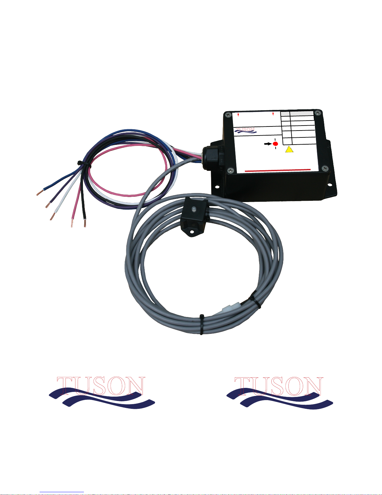
Tuson Sway Control
TSC-1000
Trailer Wire
Wires
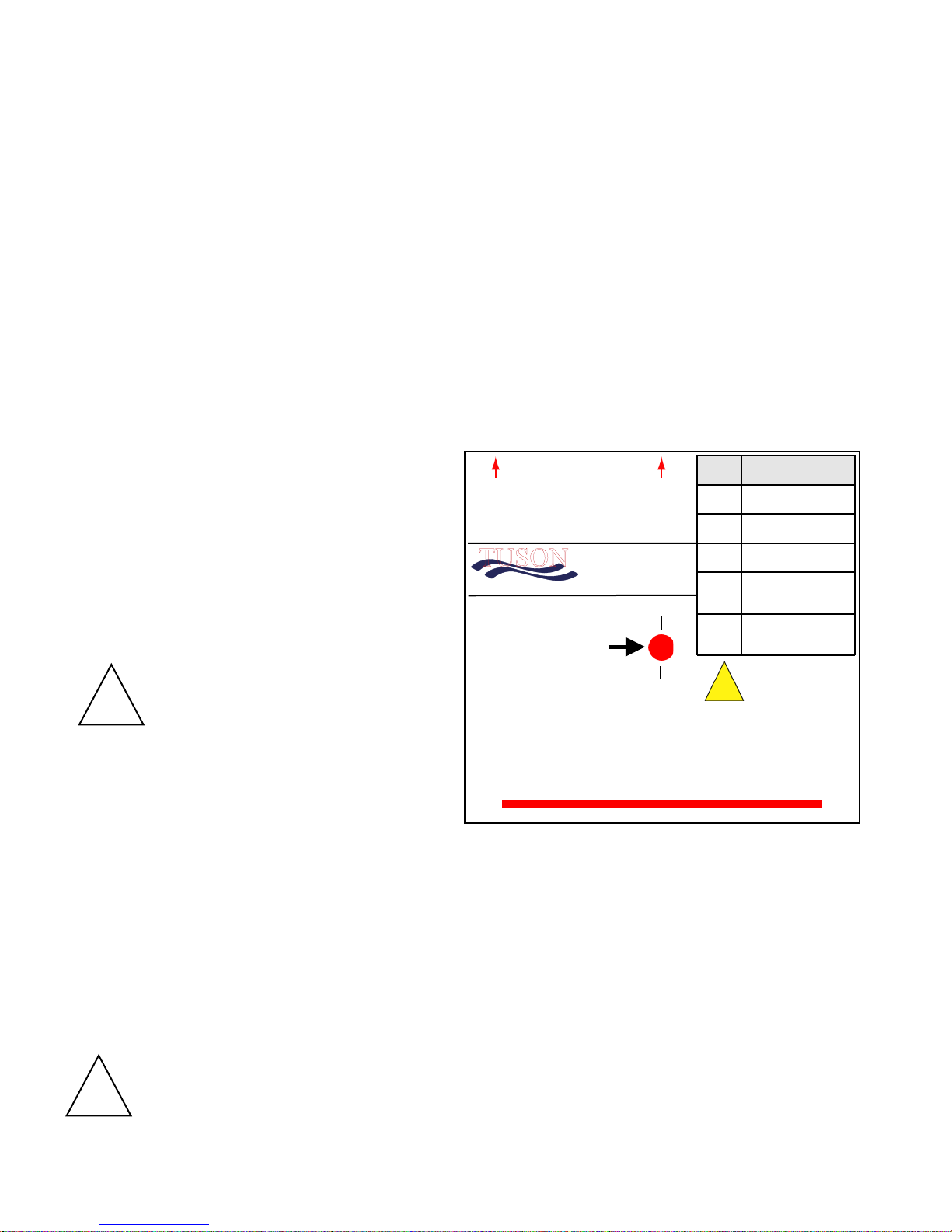
Mount with this side UP
Tuson Sway Control
(P/N: TSC-1000)
US PAT. NO. 9,026,311 / 9,415,753
AUS PAT. NO. 2014204434 / 2016204948
Module
wiring
connector
on this
side.
Module will not function if improperly
Designed and Engineered in the USA by Tuson RV Brakes, LLC
Vernon Hills, IL 60061
800-968-8766
www.tusonrv brakes.com
When
mounting,
this point
must be on
the trailer
center line.
positioned and/or oriented.
Mount this edge parallel with the trailer axle beams
approx. 1 to 10 feet back from trailer bumper hitch ball
ON A VERTICAL FRAME SURFACE
Purple
Pink
White
Blue
Black
Function
Left (driver's) side
electric brakes output
Right (curb) side
electric brakes output
Trailer battery/frame
ground point
Electric brake
controller signal from
tow vehicle
12VDC from tow
vehicle trailer
harness
Read and follow all
directions in the
Installation Instructions
to ensure the unit
operates properly.
US PAT. NO. 9,026,311 / 9,415,753
AUS PAT. NO. 2014204434 / 2016204948
475 Bunker Court
Vernon Hills, IL 60061 USA
800-968-8766
www.tusonrvbrakes.com
150 Northbourne Road
Campbellfield, VIC 3061 Australia
+61 3 9305 3484
www.tusonaustralia.com.au
November 2018
Tuson Sway Control (TSC)
!
Warning!
Tuson RV Brakes, LLC
T
USON
Installation Instructions
Section One: Trailer TSC Mounting
1.0 TSC Mounting Location:
Select a location on the trailer to mount the TSC. The suggested location is on the first trailer frame
crossmember approx. 1 to 10 feet behind the trailer bumper hitch ball and shielded from road debris. The
TSC can be mounted on either the “leading” or “trailing” edge of the crossmember as long as the correct
side is in the UP direction (as indicated on the label). The “trailing” edge is preferred since it provides the
best protection from road debris. The TSC must be securely fastened onto a vertical surface of a steel trailer
frame member to operate correctly. It must not be fastened to any other trailer surface that flexes or moves
from wind such as plastic covers or plastic walls. The center of the TSC (marked by a red dot on the TSC
label – SEE BELOW) must be positioned on the “center line” of the trailer. The longest edge of the TSC (as
indicated by a red line on the label) must be mounted parallel to the trailer axle beam(s). SEE Figure 1 on
page 2.
Trailer Wire
Function
Left (driver's) side
electric brakes output
Right (curb) side
electric brakes output
Trailer battery/frame
ground point
Electric brake
controller signal from
tow vehicle
12VDC from tow
vehicle trailer
harness
Read and follow all
directions in the
Installation Instructions
to ensure the unit
operates properly.
TSC Label
It is essential that the
TSC be oriented in the proper
direction when it is installed.
Ensure the electric brakes are
adjusted and maintained in
!
Warning!
accordance with the manufacturer's
recommendations in your owner's
manual for proper operation of the
sway control module.
Mount with this side UP
Tuson Sway Control
(P/N: TSC-1000)
US PAT. NO. 9,026,311 / 9,415,753
AUS PAT. NO. 2014204434 / 2016204948
Vernon Hills, IL 60061
800-968-8766
www.t usonrvbr akes.com
Module
wiring
connector
on this
side.
Module will not function if improperly
positioned and/or oriented.
Designed and Engineered in the USA by Tuson RV Brakes, LLC
Mount this edge parallel with the trailer axle beams
approx, 1 to 10 feet back from trailer bumper hitch ball
When
mounting,
this point
must be on
the trailer
center line.
ON A VERTICAL FRAME SURFACE
Wires
Purple
Pink
White
Blue
Black
1.1 Mounting Hardware:
The TSC should be mounted using the mounting flanges which are located on the bottom of the
unit. The customer is responsible for supplying the mounting bolts. Use four #10 self tapping screws with
star lock washers to mount the TSC to the trailer. It is recommended that star lock washers be
used and you must securely tighten the mounting bolts to hold the TSC firmly in position and to avoid
becoming loose from vibration.
You can NOT drill holes in the TSC for any reason. Drilling holes or puncturing the unit VOIDS
YOUR WARRANTY.
DO NOT SPRAY HIGH PRESSURE WATER ON THE TSC. The TSC is a weather sealed,
!
water resistant unit but it is not designed to withstand direct, high pressure spray
from a power washer.
Warning!
Page 1
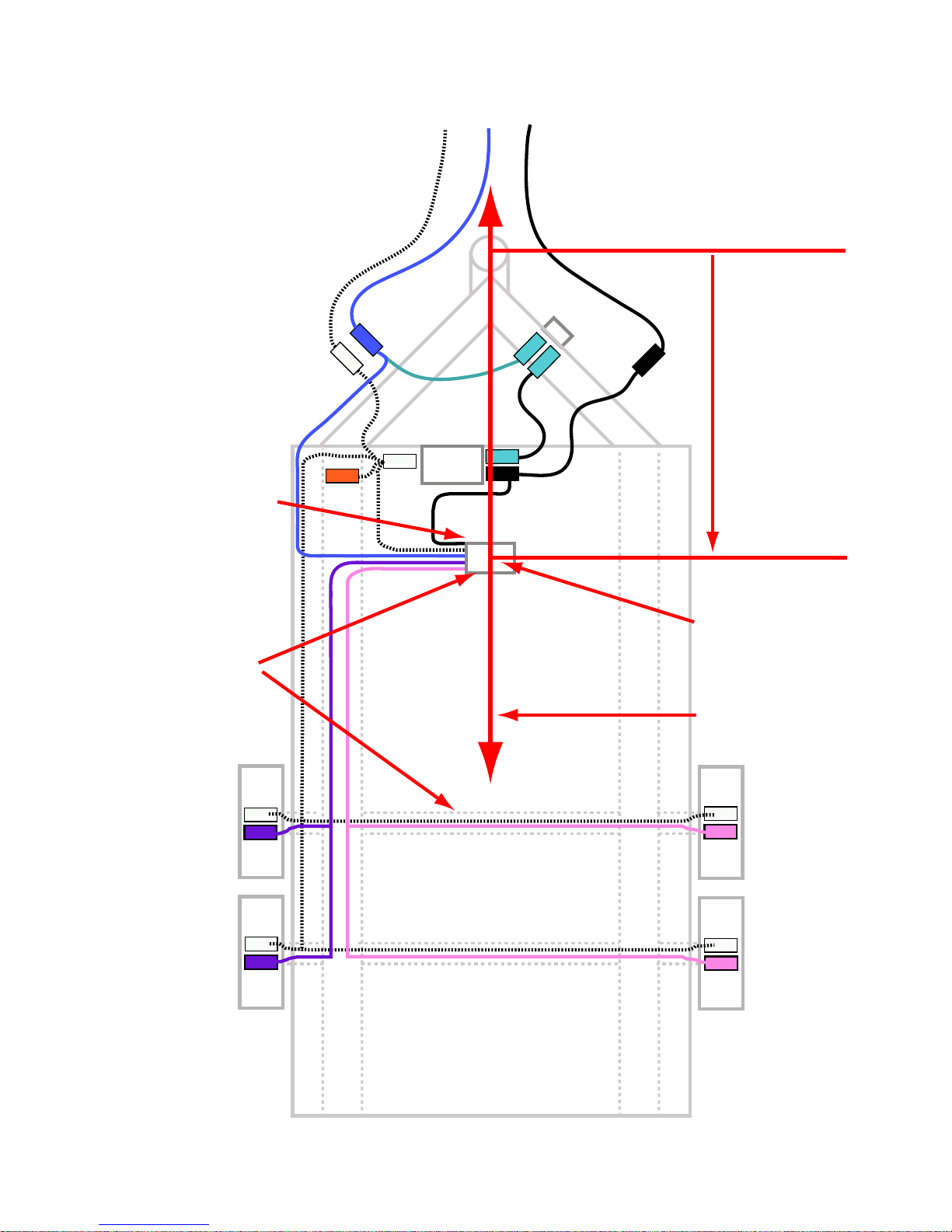
Full Size +12V
Trailer Battery
Break-Away
Switch
-
+
Frame
Ground
Left Front
Driver’s Side
Electric Brake
Left Rear
Driver’s Side
Electric Brake
Right Rear
Curb Side
Electric Brake
Right Front
Curb Side
Electric Brake
Trailer
Centerline
TSC mounted
with the correct
side in the
UP direction
TSC Center on
Vertical Frame
Surface on Trailer
Centerline
Edge Parallel
with Axle Beams
1
Tuson
Sway
Control
Section One: TSC Mounting, continued
Mount on
trailer frame
crossmember
approx.
1 to10 feet
behind hitch
ball
Page 2
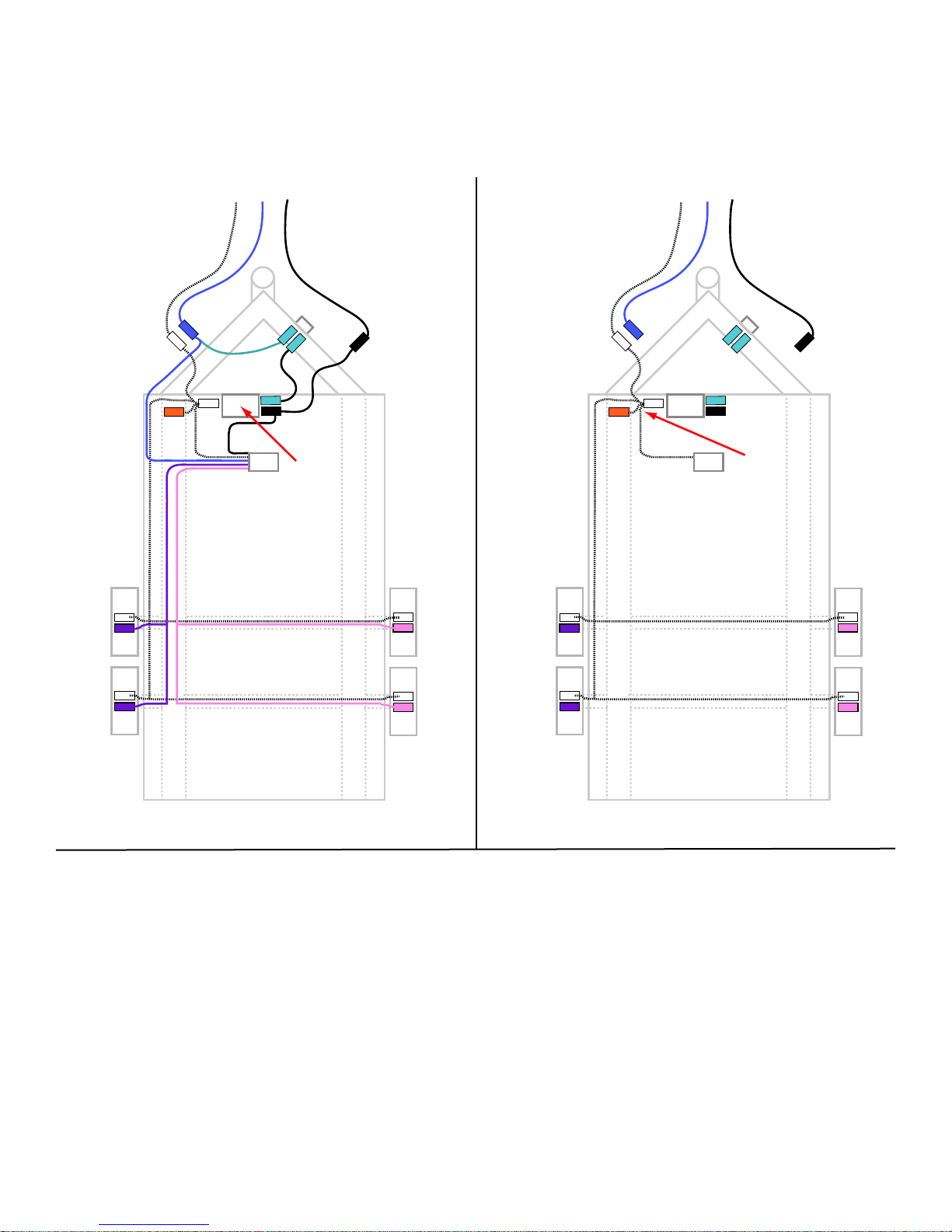
Section Two: TSC Wiring
Full Size +12V
Trailer Battery
Break-Away
Switch
-
+
Frame
Ground
Left Front
Driver’s Side
Electric Brake
Left Rear
Driver’s Side
Electric Brake
Right Rear
Curb Side
Electric Brake
Right Front
Curb Side
Electric Brake
Must Use
Full Size
Trailer Battery
2
Tuson
Sway Control
Full Size +12V
Trailer Battery
Break-Away
Switch
-
+
Frame
Ground
Left Front
Driver’s Side
Electric Brake
Left Rear
Driver’s Side
Electric Brake
Right Rear
Curb Side
Electric Brake
Right Front
Curb Side
Electric Brake
All Grounds
Connected
Together
3
Tuson
Sway Control
2.2 Trailer Battery:
The trailer must be equipped with a full size 12
volt battery. Small, gel-cell type batteries
must not be used with the TSC.
2.3 Ground Connections:
The tow vehicle ground, trailer battery ground,
trailer frame ground, TSC ground (white) wire
and the electric brake ground wires (on both
sides of the trailer) must all be securely
connected together with 14 gauge wire (min.) in
order for the TSC to function properly.
Page 3
 Loading...