

Ultrasonic Sensor
Diffuse Mode Sensor
RU40U-M12-AP6X2-H1141
Type designation RU40U-M12-AP6X2-H1141
Ident no. 100000279
Function Ultrasonic diffuse mode sensor
Range 40…400 mm
Resolution 0.5 mm
minimum measuring range 50 mm
minimum switching range 5 mm
Ultrasound frequency 300 kHz
Repeat accuracy 0.15 % of full scale
Linearity error
Edge lengths of the nominal actuator 20 mm
Approach speed
Pass speed
Operating voltage 10…30 VDC
Residual ripple 10 % U
DC rated operational current
No-load current I
Residual current
Response time typical 60 ms
Readiness delay 300 ms
Communication protocol IO-Link
Output function NO/NC, PNP
Switching frequency 10.4 Hz
Hysteresis
Voltage drop at I
Short-circuit protection yes/ Cyclic
Reverse polarity protection yes
Wire breakage protection yes
IO-Link
IO-Link Specification V 1.1
IO-Link port type Class A
Communication Mode COM 2 (38.4 kBaud)
Process data width 16 bit
Measured value information 15 bit
Switchpoint information 1 bit
Frame type 2.2
Minimum cycle time 2 ms
Function Pin 4 IO-Link
Function Pin 2 DI
Maximum cable length 20 m
Profilunterstützung Smart Sensor Profil
0
e
ð ± 0.5 %
ð 5 m/s
ð 2.9 m/s
ss
ð 150 mA
ð 50 mA
ð 0.1 mA
ð 5 mm
ð 2.5 V
■ Smooth sonic transducer face
■ Cylindrical housing M12, potted
■ Connection via M12 × 1 male connector
■ Teach range adjustable via connection
cable
■ Blind zone: 4cm
■ Range: 40cm
■ Resolution: 0.5mm
■ Aperture angle of sonic cone: 15°
■ Switching output, PNP, programmable
via IO-Link
■ NO/NC programmable
■ IO-Link
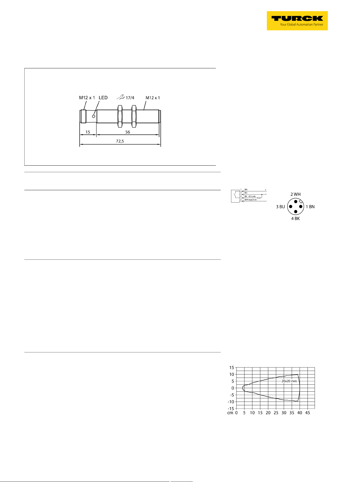
Wiring Diagram
Functional principle
Ultrasonic sensors capture a multitude of objects contactlessly and wear-free with ultrasonic waves. It does not matter whether the
object is transparent or opaque, metallic or
non-metallic, firm, liquid or powdery. Even environmental conditions such as spray, dust or
rain hardly affect their function.
The sonic cone diagram indicates the detection range of the sensor. In accordance with
standard EN 60947-5-2, quadratic targets in
a range of sizes (20 x 20 mm, 100 x 100 mm)
and a round rod with a diameter of 27 mm are
used.
Important: The detection ranges for other targets may differ from those for standard targets
due to the different reflection properties and
geometries.
Sonic Cone
Edition • 2019-11-09T22:15:43+01:00
1 / 5 Hans Turck GmbH & Co.KG ñ

Ultrasonic Sensor
Diffuse Mode Sensor
RU40U-M12-AP6X2-H1141
Design Threaded barrel,M12
Radiation direction straight
Dimensions 72.5 x Ø 12 mm
Housing material Metal, CuZn, Chrome-plated
Max. tightening torque of connector B 20 Nm
Transducer material Plastic, Epoxyd resin and PU foam
Electrical connection Connectors, M12 × 1, 4-wire
Protection class IP67
Ambient temperature -10…+60 °C
Storage temperature -40…+80 °C
Declaration of conformity EN ISO/IEC EN 60947-5-2
Vibration resistance IEC 60068-2
MTTF 377 years
MTTF note acc. to SN 29500 (Ed. 99) 40 °C
Switching state LED, Yellow
Object detected LED, Green
Edition • 2019-11-09T22:15:43+01:00
2 / 5 Hans Turck GmbH & Co.KG ñ

Ultrasonic Sensor
Diffuse Mode Sensor
RU40U-M12-AP6X2-H1141
Mounting instructions/Description
Setting the switchpoint
The ultrasonic sensor features a switching output with a
teachable switching point. The green and yellow LEDs
indicate whether the sensor has detected the object.
A switching point or a switching window is taught in.
This must be within the detection range. In this operat-
ing mode the background is suppressed.
Teach
ñ Position the object at the beginning of the protection
area
ñ Short-circuit pin 2 (WH) against Ub for 2–7 seconds
to teach in an individual switching point or the begin-
ning of the switching window
ñPlace object at the end of the switching range
ñ Short-circuit pin 2 (WH) against Ub for 8–11 seconds
to teach in the end of the switching window
After a successful teach-in, the yellow LED flashes
at 2 Hz and the sensor runs automatically in normal
mode.
Optional: Short-circuit pin 2 (WH) against Ub for 12–17
seconds to switch between NC and NO function (no ob-
ject required)
ñ Return to normal operating mode after 17 s or more.
LED response
In standard operating mode, the two LEDs indicate the
switching state of the sensor.
ñ Green: Object within the detection range but not in
switching range
ñ Yellow: Object is within the switching range
ñ Off: Object is outside the detection range or signal
loss
Edition • 2019-11-09T22:15:43+01:00
3 / 5 Hans Turck GmbH & Co.KG ñ

Ultrasonic Sensor
Diffuse Mode Sensor
RU40U-M12-AP6X2-H1141
Accessories
Type code Ident no. Description Dimension drawing
MW-12 6945003 Mounting bracket for threaded barrel sensors; material: Stain-
less steel A2 1.4301 (AISI 304)
BSS-12 6901321 Mounting clamp for smooth and threaded barrel sensors; ma-
terial: Polypropylene
Function accessories
Type code Ident no. Description Dimension drawing
TBEN-S2-4IOL 6814024 Compact multiprotocol I/O module, 4 IO-Link Master 1.1
Class A, 4 universal PNP digital channels 0.5 A
USB-2-IOL-0002 6825482 IO-Link Master with integrated USB port
VB2-SP1 A3501-29 Teach adapter
Edition • 2019-11-09T22:15:43+01:00
4 / 5 Hans Turck GmbH & Co.KG ñ

Ultrasonic Sensor
Diffuse Mode Sensor
RU40U-M12-AP6X2-H1141
Function accessories
Type code Ident no. Description Dimension drawing
NQ-EP4L 100004784 Compact multiprotocol I/O module, 4 IO-Link Master 1.1
Class A, 4 universal PNP digital channels 0.5 A
Edition • 2019-11-09T22:15:43+01:00
5 / 5 Hans Turck GmbH & Co.KG ñ
 Loading...