

Page 1
FDNQ-ES11-T
This station is designed specically for use with 2-NC and 1-NO E-stop devices. It provides a
convenient way to connect redundant circuits to the machine safety switches using o the shelf
cordsets. The station monitors the machine safety switch state. The state of the switch is reported
to the PLC via DeviceNet™.
The machine safety switch is connected via an eight pin eurofast® connector. Four pins are
required to provide redundant safety switch circuits. Two pins are used to monitor the state of
the machine safety swtich. Two pins are used as an output circuit. This output can be set by the
PLC on DeviceNet.
The auxiliary power is connected via four pin eurofast connector. Two of the pins are used to
provide external power for the station’s input and output circuits. Two of the pins are used to
provide redundant safety switch circuits.
The FDNQ-ES22-T supports explicit messaging, poll, change of state, and cyclic I/O messages.
These connections are established through UCMM or predened master/slave connection set.
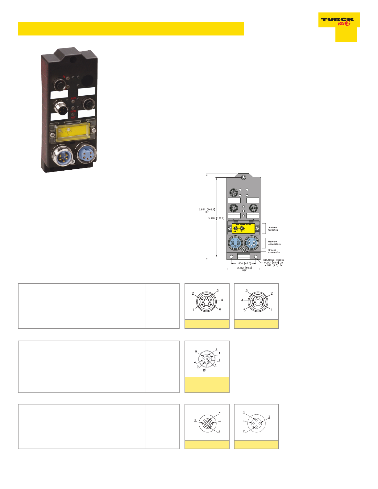
Dimensions:
DeviceNet™
Style: 5-pin minifast®
Cordset: Bus Line use RSM RKM 579-*M
Tee: Bus Line use RSM 2RKM 57
Safety Switch
Style: 8-pin eurofast®
Cordset: RSC RKC E80-*M
Auxiliary Power: E1 and E2 Circuit
Style: 4-pin eurofast®
Cordset: RSC RKC E40-*M
* Cable length in meters.
1 = Shield
2 = V+
3 = V4 = CAN_H
5 = CAN_L
1 = IN
2 = OUT
3 = AUX (+)
4 = SC1
5 = SC1c
6 = SC2
7 = SC2c
8 = AUX (-)
1 = AUX (+)
2 = SC1
3 = SC2
4 = AUX (-)
Female
Female
Female
Male
Male
TURCK Inc. Minneapolis, MN 55441 10240396 Rev 1.1 6/12 1
Page 2
FDNQ-ES11-T
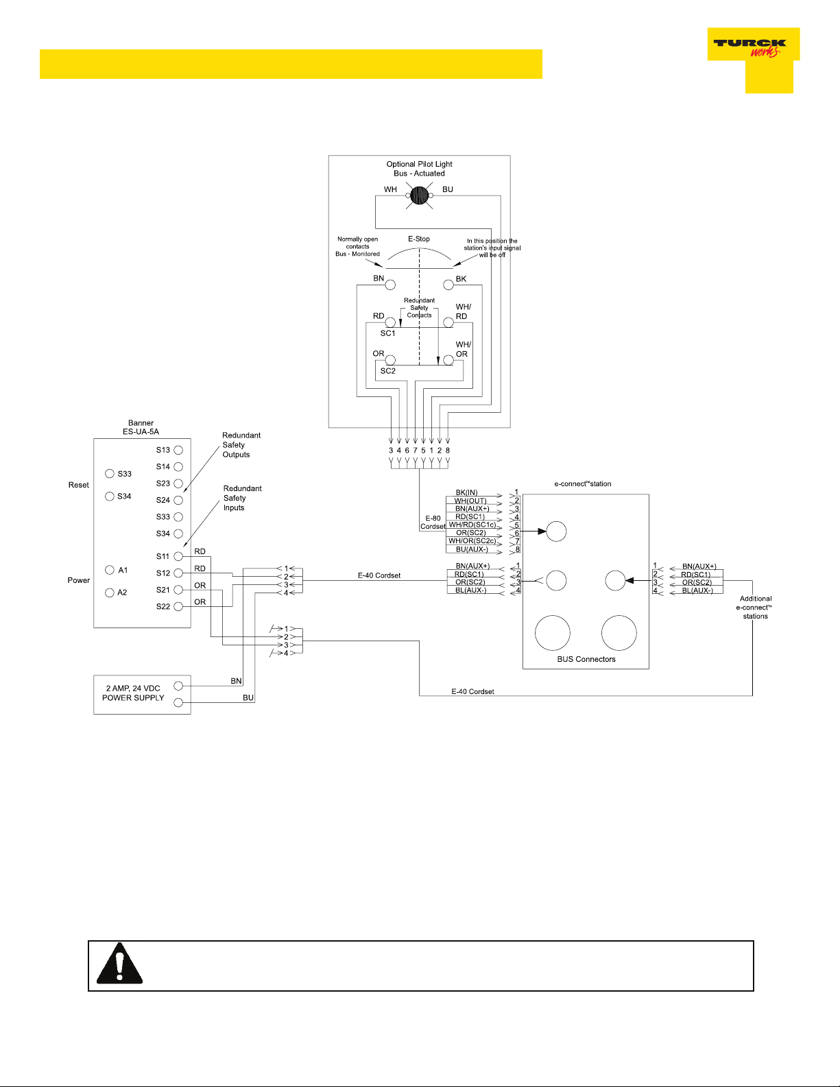
Wiring Conguration
The drawins depicted in this publication are general in nature and intended as guidelines. Each application is unique. It is the
responsibility of the user to ensure all applicable jurisdictional codes and regulations are satised, and that installation and
maintenance instruction are followed.
WW
ARNING !ARNING !
W
ARNING !
WW
ARNING !ARNING !
NEVER bypass or otherwise defeat the protective function of a safety switch. To do so may create an unsafe
situation which could lead to serious injury or death.
TURCK Inc. Minneapolis, MN 55441 10240396 Rev 1.1 6/12 2
Page 3

FDNQ-ES11-T
Module Specications:
Supply Voltage
Bus Power 11-26 VDC
Internal Consumption <40 mA
Auxiliary Power 18-26 VDC
Input Circuits
Input Voltage (V+) 18-26 VDC auxiliary powered (optically isolated from bus)
Input Signal Current (Input) Off <2 mA
On = 3.0-3.4 mA at 24 VDC
Input Delay 2.5 ms
Output Circuits
Output Voltage 18-26 VDC auxiliary powered (optically isolated from bus)
Output Load Current 0.5 A per output
Maximum Switching Frequency 100 Hz
I/O LED Indications
Off = Off
Green = On
Aux Status LED
Off = No power
Green = Aux power present
Module Status LED
Green: working properly
Flashing green: detecting autobaud rate
Flashing red: missing aux power
Network Status LED
Green: established connection
Flashing Green: ready for connection
Flashing Red: connection time-out
Red: connection not possible
Adjustments
Address 0-63 via Rotary Switch, programmable
Data Rate Autobaud
Housing
Material Glass filled nylon with nickel plated brass connection
Enclosure NEMA 1, 3, 4, 12, 13 and IEC IP 67
Operating temperature -25° to 70°C (-13° to 158°F)
TURCK Inc. Minneapolis, MN 55441 10240396 Rev 1.1 6/12 3
Page 4

FDNQ-ES11-T
I/O Data Mapping
F0155/FDNQ-ES11-T.eds
Product Code: 7/2481 (9B1 hex)
Input Data
Output Data
Abbreviations
I = Input Data (0= OFF, 1= ON)
ISS = Input Short Status (0=Working, 1=Fault)
IOS = Input Open Status (0=Working, 1=Fault)
IGS = Input Group Status (0=Working, 1=Fault)
Byte Bit 7 Bit 6 Bit 5 Bit 4 Bit 3 Bit 2 Bit 1 Bit 0
APS - - - - - - - I-0
Byte Bit 7 Bit 6 Bit 5 Bit 4 Bit 3 Bit 2 Bit 1 Bit 0
- - - - - - - - O-0
O = Output Data (0=OFF, 1=ON)
OS = Output Status (0=Working, 1=Fault)
OGS = Output Group Status (0=Working, 1=Fault)
APS = Aux Power Status (0=OFF, 1=ON)
TURCK Inc. Minneapolis, MN 55441 10240396 Rev 1.1 6/12 4
 Loading...