

34567
Slave Addr
ess (0-99)
C4C5C6C7C0
C3
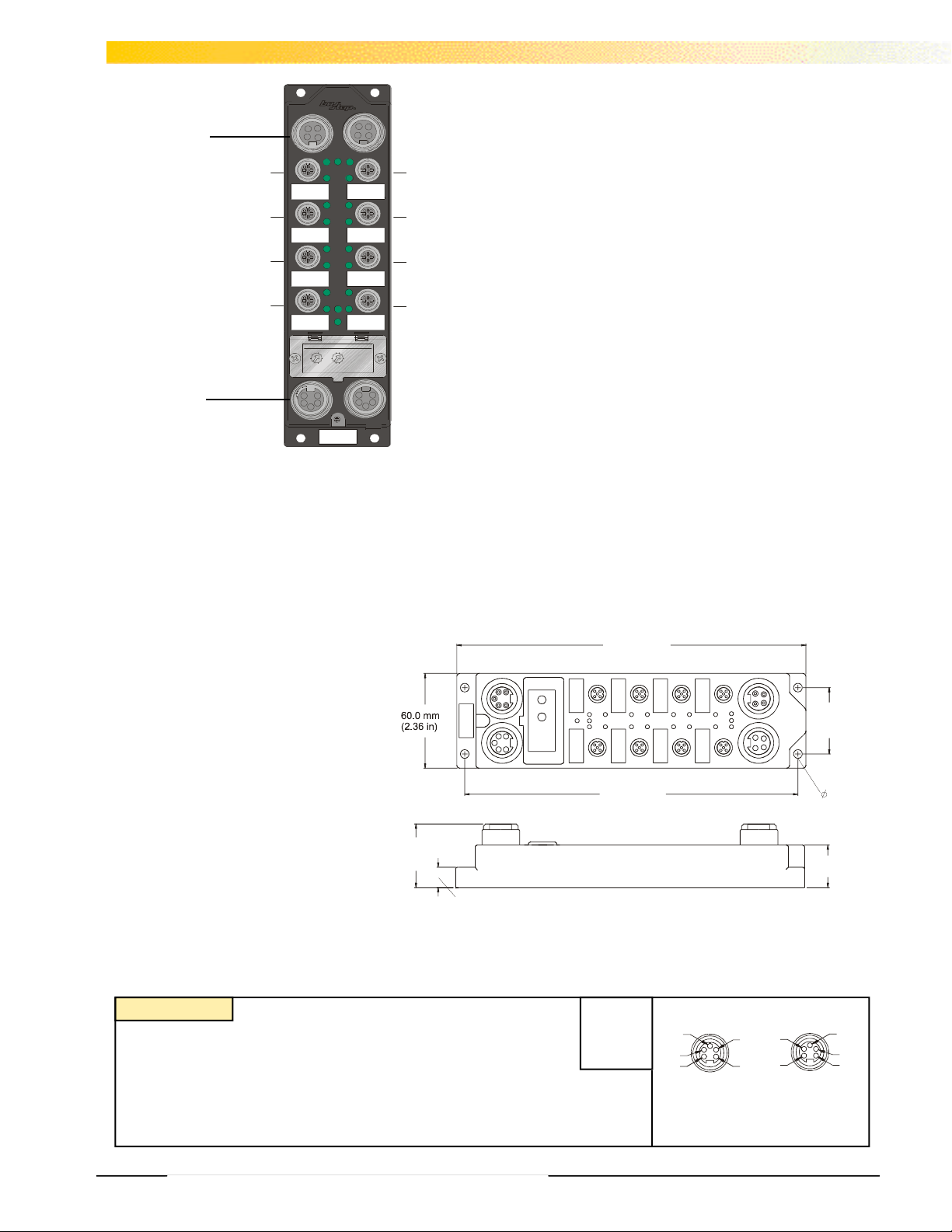
“T” Type
1
2
345
220.0 mm
(1.06 in)
42.0 mm
(1.65 in)
5.3mm
(.209in)
Aux Power
This busstop® station takes in up to twelve discrete three-wire inputs or
six discrete four-wire input points per node. There are two dual output
connectors.
4 Aux Powered
Outputs
“2G” Type
C1
(C0, C4)
12 DeviceNet
C2
Powered Inputs
“2P” Type
(C1-C3, C5-C7)
2
2 3
4
1
1
5
0
0
9
6
9
8
8
7
x10 x1
DeviceNet
FDNP-P1204G-TT
• Advanced DeviceNet™ Station
• 6 x 2 discrete inputs and 2 x 2 discrete
outputs
Applications
• For wet or dry environments
• For use with twelve three-wire or six four-
wire proximity and photoelectric sensors,
and four discrete actuators
There are two inputs per connector-one on pin four and one on pin two.
Each input connector produces four bits of data- two input state bits,
one short-circuit status bit and one open-circuit status bit. The state bit
is set when the discrete input device closes. The LED at each input
point turns green when the input is one. Each input pair is monitored
for short-circuits and open-circuits. Open-circuit detection can be
enabled for each input pair using a software configuration tool. The
status bits automatically reset when the fault is removed.
There are two outputs per connector-one on pin four and one on pin
two. Each output connector consumes two output control bits and
produces two output status bits-one control bit and one status bit for
each output. The LED at each output point turns green when the
output is on. Each output pair is monitored for short-circuits and opencircuits.
The node address and communication rate can be set using the rotary
switches located under the device cover or through software node
commissioning. The unit automatically detects the communication rate.
The FDNP-P1204G-TT supports explicit messaging, poll, change of
state, and cyclic I/O messages. These connections are established
through UCMM or predefined master/slave connection set.
Dimensions
(8.66 in)
Features
• PNP short-circuit protected
210.0 mm
(8.27 in)
inputs with open-circuit protection
• 0.5amp short-circuit protected outputs
• Glass filled nylon with nickel plated brass
40.3 mm
(1.59 in)
27.0 mm
connectors
• Rotary Address Switches
13.0 mm
(0.51 in)
Connectors
DeviceNet
Style: 5-Pin minifast®
Cordset: Bus Line use RSM RKM 579- *M
Tee : Bus Line use RSM 2RKM 57
InterlinkBT™ 10240143 Rev. 2.0 11/01
1 = Shield
2 = V +
3 = V 4 = CAN_H
5 = CAN_L
3
4
5
Male
Through Bus
2
1
Female
1
2 ( ) WH
4 ( ) BK
2 (
3 (-) BU
Output A
Output B
3
4
2
1
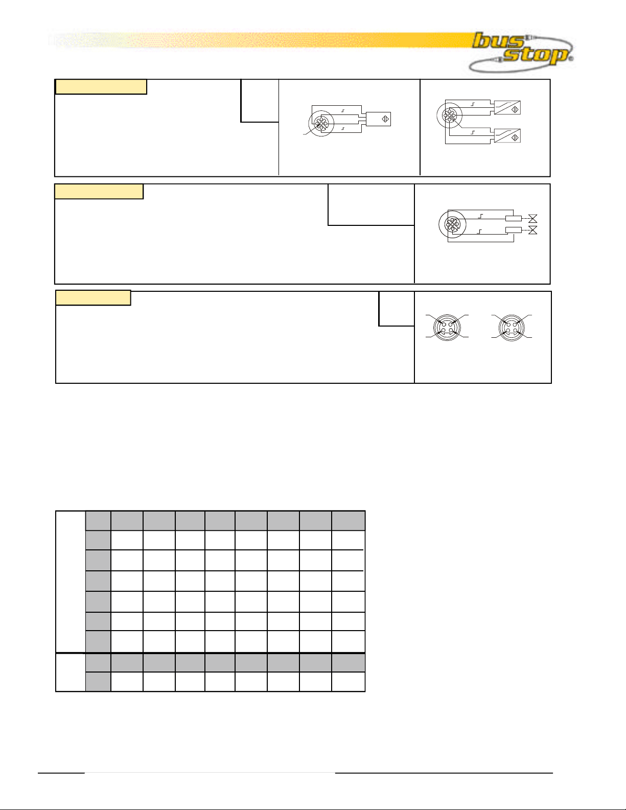
Connectors
Type “2P”
Style: 5-Pin eurofast
Cordset: Sensor with 2 Signals use
RK 4.4T-*-RS 4.4T
1= V +(A)
2 = Input B
3 = V 4 = Input A
5 = V +(B)
3 (-) BU
1 (+) BN
5
Splitter: Splitter and 2 Sensors
use VBRS 4.5-2RK 4T-*/*/S818
Type “2G”
Style: 5-Pin eurofast
Cordset: Dual Ouput use RK 4.4T-*-RS 4.4T
Sensor with 2 Signals
1 = N/C
2 = Output B (odd numbers)
3 = GND
4 = Output A (even numbers)
5 = PE
Splitter: Dual Output or Dual Valve use
VB2-RS 4.5T-*/2VAS 22-A528-*/*(“A”Style valve plug, other’s available)
Field Wireable: Dual Output use BS 8141-0
Type “T”
Style: 4-Pin minifast®
Cordset: Aux Power use
RSM RKM 46- *M
Tee : Aux Power use RSM 2RKM 40
1= Aux +
2= E+
3= E4= Aux-
3 (-) BU
4 ( ) BK
1 (+) BN
5 (+) GY
2 ( ) WH
3 (-) BU
INPUT A
INPUT B
Splitter and 2 Sensors
4 (
) BK
) WH
3 (-) BU
Dual Output
1
2
3
4
FemaleMale
Auxiliary Power
I/O Data Mapping
Item Number/EDS File: F0062/I0062_xx.eds
Product Code: 7/993 (3E1 hex)
Bit 7 Bit 4Bit 5Bit 6 Bit 0Bit 1Bit 2Bit 3
Byte
0
APS
-
ISS-7 ISS-6 ISS-1ISS-2ISS-3ISS-4ISS-5
IOS-6
Input
Data
1
2
IOS-7 IOS-1IOS-2IOS-3IOS-5 IOS-0
3
4
IOS-7 IOS-6 IOS-5 IOS-4 IOS-3 IOS-2 IOS-1 IOS-0
5
Bit 7 Bit 4Bit 5Bit 6 Bit 0Bit 1Bit 2Bit 3
Output
Data
Byte
-
- - -
Abbreviations
I = Input Data (0=OFF, 1=ON) O = Output Data (0=OFF, 1=ON)
ISS = Input Short Status (0=Working, 1=Fault) OS = Output Status (0=Working, 1=Fault)
IOS = Input Open Status (0=Working, 1=Fault) OGS = Output Group Status (0=Working, 1=Fault)
IGS = Input Group Status (0=Working, 1=Fault) APS = Aux Power Status (0=OFF, 1=ON)
I-5I-7 I-3I-4 I-1I-2 I-0I-6
- -
IOS-4
I-8I-9I-10I-11
ISS-0
ISS-0
ISS-10 ISS-9 ISS-8OSS-3 OSS-0OSS-1OSS-2 ISS-11
OOS-0 IOS-11 IOS-10 IOS-9 IOS-8OOS-2OOS-3 OOS-1
O-3 O-2 O-1 O-00
InterlinkBT™ 10240143 Rev. 2.0 11/01
2

Module Specifications
FDNP-P1204G-TT
12 PNP Input and Four 0.5A
Output, Per Point Diagnostic
Supply Voltage
Bus power 11-26 VDC
Internal current consumption <100 mA, plus sum of sensor currents (from bus power)
Auxiliary power 18-26 VDC
Input Circuits (12) PNP 3-wire sensors or dry contacts or (6) PNP 4-wire sensors
Input voltage (V+) 11-26 VDC (from bus power)
Open circuit current (V+) < 1mA
Sensor current (V+) <80 mA per input
Input signal current (Input) OFF <2mA
ON 3.0-3.4 mA at 24VDC
Input delay 2.5 ms
Output Circuits (4) DC actuators
Output voltage 18-26 VDC (from auxiliary power)
Output load current 0.5 A per output (from auxiliary power)
Open circuit current < 1 mA per output
Maximum switching frequency 100 HZ
I/O LED Indications
Amber=Open-circuit
Off=Off
Green=On
Red=Short-circuit
Module Status LED
Green: working properly
Flashing green: detecting autobaud rate
Flashing red: I/O short-circuit
Network Status LED
Green: established connection
Flashing Green: ready for connection
Flashing red: connection time-out
Red: connection not possible
Adjustments via Rotary Switch
Address 0-63
Communication Rate Auto/125k/250k/500k
Housing
Material glass filled nylon with nickel plated brass connectors
Enclosure NEMA 1,3,4,12,13 and IEC IP 67
Operating temperature -25° to 70°C (-13° to 158°F)
InterlinkBT™ 10240143 Rev. 2.0 11/01
3
 Loading...