

Page 1
Quick Start Guide
TCS-C ceiling series
Models covered by this Quick Start Guide
TCS-C35T, TCS-C50T ceiling speakers.
Thank you for choosing a TURBOSOUND loudspeaker product for your application. If you would like further information
about this or any other TURBOSOUND product, please contact us. A detailed user manual on this product is available from
our web site at www.turbosound.com.
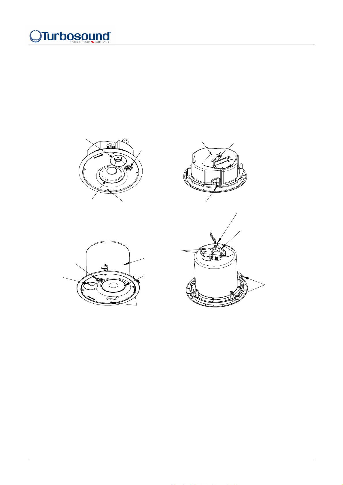
TCS-35T
Twe ete r
Tap selector
Terminal cover plate
Strain relief fitting
LF loudspeaker
Attachment screws
Rotating mounting tabs
Input connector
Strain relief fittin g
TCS-50T
Terminal cover plate
Tap se l ec t or
Tweet er
Unpacking the TCS series loudspeaker
After unpacking the unit please check carefully for damage. If damage is found, please notify your supplier at once. You,
the consignee, must instigate any claim. Please retain all packaging in case of future re-shipment.
Steel fire can
LF loud speaker
Attachment screws
Rotati ng mounti ng tabs
System Requirements
TCS-C series ceiling loudspeakers are passive loudspeaker systems, and require only one amplifier channel for correct
operation, the frequency splitting between the LF driver and the HF driver being accomplished by the internal passive
crossover network.
Using Ceiling Loudspeakers with Subwoofers
If subwoofers are required, additional amplifier channels and external electronic crossovers will be required. The
Turbosound LMS series digital management systems are recommended for this purpose.
TCS-C series Quick Start Guide - Page - 1
Page 2
Quick Start Guide
TCS-C ceiling series
Amplifier Considerations
Turbosound ceiling speakers should be driven by high quality power amplifiers designed for true professional use.
Amplifiers should be capable of delivering long term broadband power equal to the loudspeaker’s program power rating
at the stated nominal impedance. Always operate your power amplifiers at maximum gain for the best headroom and
signal/noise ratio, controlling the overall system volume from the mixing console. The use of under-powered amplifiers
must be avoided as heavily clipped signals can cause permanent loudspeaker damage.
In a distributed system the amplifiers must be capable of supplying broadband power equivalent to the sum of the power
rating of the loudspeakers (taking into account the individual power taps selected) connected to that particular amplifier
channel.
Installation Procedure
1. Cut a hole in the ceiling tile using a circular cutter set the size listed below and pull the wiring through the hole.
TCS-C35T cut-out diameter is 215mm
TCS-C50T cut-out diameter is 240mm
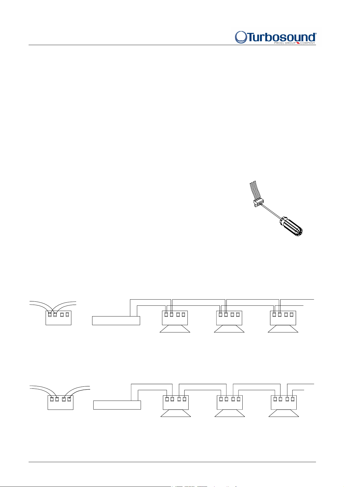
2. Connect the wiring to the removable connector. A 4-way Phoenix-style
connector is supplied with the loudspeaker. Strip the insulation back by
5mm (3/16”), insert the bare ends of the wire into the connector (do not tin
the wire) and screw down the hold-down screw with a small flat blade
screwdriver.
3. There are two possible connection strategies, depending on the desired circuit result when a single unit is disconnected
for trouble shooting or servicing:
Parallel Input Terminals. This allows the circuit to remain intact whenever a speaker is disconnected. Connect the outgoing
pair of wires to the same terminals as the incoming pair of wires.
Inp+Link
-
+
-
Power Amplifier
Loop-through Terminals. All loudspeakers after this unit will be disconnected, helping to isolate problems to a section of
the distributed line while leaving the wires connected to the connector.
+ -
Input+Link
- -
+ --
Speaker 1 Speaker 2 Speaker 3
Input+Link
+ --
Input+Link
+
Inp+Link
- -
+
Power Amplifier
TCS-C series Quick Start Guide - Page - 2
+ -
Input+Link
- -
+ --
Speaker 1 Speaker 2 Speaker 3
Input+Link
+ --
Input+Link
+
Page 3

Quick Start Guide
TCS-C ceiling series
4. The mounting hardware consists of two tile rails and a ‘C’ plate
(these are supplied with the TCS-C35T, and as an optional accessory
for the TCS-C50T). Insert the tile rails through the hole in the ceiling
tile and align them parallel to each other on either side of the hole,
and with the ends positioned over the ceiling T grid. Insert the ‘C’
plate through the hole and snap the tabs onto the tile rails as shown.
Position directly over the hole in the ceiling tile and secure with the
fixing screws supplied. Note that the provision of multiple fixing
holes in the tile rails allows the speaker to be positioned away from
the centre of the tile if desired.
5. Plug the connector into the socket in the loudspeaker’s terminal cup. The connector is polarised to avoid the possibility
of mis-connection. The terminal cover also acts as the strain relief. Rotate the cover and tighten the retaining screw.
6. Connect the safety tab to a separate support point. Consult construction codes in your region.
7. Insert the speaker into the ceiling and secure the fixing arms. Offer the loudspeaker into the ceiling until the back of the
front baffle rim touches the ceiling tile. Turn the attachment screws to tighten the fixing arms. Note that the first 1/4 turn
rotates the arm outwards and subsequent turns tighten the tab down onto the ceiling tile. DO NOT OVERTIGHTEN.
8. Adjust the voltage tap selector for desired level. The selector is
located on the front baffle, and should be adjusted before fitting
the grille. In some installations it may be preferable to leave
grilles off until final adjustment of the tap selectors has been
completed for all loudspeakers.
9. Apply the logo badge to the grille in the desired location if required, and fit the loudspeaker grille by pressing the grille
firmly into place until it is flush with the rim.
Painting before Installation
The loudspeaker’s white finish matches most décor schemes and does not need further finishing. However where interior
design requires an alternative colour this can be easily accomplished. The loudspeaker can either be painted before
installation, or where the rim needs to be finished at the same time as the ceiling the rim can be painted after locating in
the ceiling. The speaker will accept almost any type of emulsion or oil-based paint. Two coats are recommended.
TCS-50T TCS-35T
1
6
6
0
1
3
0
0
0
V
15
6
1
7.5
V
5
0
1
7
0
3
60
7.5
3
0
1
5
0
V
6
1
1
6
1
0
3.75
V
5
.
0
7
7
5
1
30
Clean the rim and grille with a light solvent such as white spirit. Do not use gasoline, kerosene, acetone, MEK, paint
thinner, harsh detergents or other chemicals, all of which may damage the loudspeaker. After cleaning, apply two coats of
paint, using a roller or brush, or by spraying.
Painting the Speaker with the Ceiling
Using the paint shield provided, paint the speaker and remove the shield. To paint the grille, first remove the logo and
grille cloth backing. It is advisable to spray the grille to avoid the mesh becoming clogged with paint from a roller or
brush, which may impair the sound quality. Replace the grille cloth and the logo.
TCS-C series Quick Start Guide - Page - 3
Page 4

Quick Start Guide
TCS-C ceiling series
Technical Specifications
TCS-C35T TCS-C50T
Dimensions 235mm (9.2”) dia x 112mm (4.4”) deep
100mm (3.9”) minimum mounting depth
Hole cut-out 215mm (8.5”) 240mm (9.5”)
Net weight 2.3kg (5.1lbs) 3.4kg (7.5lbs)
Components 1 x 3.5” (89mm) LF driver
1 x 1” (25mm) HF tweeter
Frequency response 100Hz – 20kHz ±4dB 75Hz – 22kHz ±4dB
Nominal dispersion 150ºH x 150ºV @-6dB points 180ºH x 180ºV @-6dB points
Sensitivity 85dB (half space), 1w @ 1m 92dB (half space), 1w @ 1m
Power handling 30 watts r.m.s., 60 watts program 75 watts r.m.s., 150 watts program
Maximum SPL 100dB continuous, 106dB peak 110dB continuous, 116dB peak
Transformer taps 30W, 15W, 7.5W (100 volt line)
30W, 15W, 7.5W, 3.75W (70 volt line)
Nominal impedance 16 ohms nominal (low impedance) 16 ohms nominal (low impedance)
Construction Paintable injection moulded ABS Paintable injection moulded ABS
Grille Powder coated perforated steel backed
with acoustic cloth
268mm (10.5”) dia x 83mm (3.3”) deep
206mm (8.1”) minimum mounting depth
1 x 5” (127mm) LF driver
1 x 1” (25mm) HF tweeter
60W, 30W, 15W (100 volt line)
60W, 30W, 15W, 7.5W (70 volt line)
Powder coated perforated steel backed
with acoustic cloth
Connector Phoenix 4-way connector Phoenix 4-way connector
Protection Thermal fuse disconnects speaker from
distributed system
Standards Conforms to BS5839 part 8 1988 and
IEC/EN 60849 fire prevention
Thermal fuse disconnects speaker from
distributed system
Conforms to BS5839 part 8 1988 and
IEC/EN 60849 fire prevention
Spares and Accessories
LS-50 5” low frequency loudspeaker
LS-35 3.5” low frequency loudspeaker
TW-52 1” high frequency tweeter
PX-TCS-C50T Passive crossover network
PX-TCS-C35T Passive crossover network
MG-C50 Metal grille
MG-C35 Metal grille
TCS-CTR Tile rail (supplied with TCS-C35T, optional for TCS-C50T)
TCS-CCP35 C plate for TCS-C35T (supplied with TCS-C35T)
TCS-CCP50 C plate for TCS-C50T (optional accessory for TCS-C50T)
Turbosound Ltd., Star Road, West Sussex RH13 8RY, UK
tel: +44 (0)1403 711447 fax: +44 (0)1403 710155 www.turbosound.com
version 1.0 05/10
TCS-C series Quick Start Guide - Page - 4
 Loading...