

Page 1

REFRIGERATOR MANUFACTURER
Turbo air
R
TGM
12SD*
TGF
-
5SD
TGF
47SD*
SUPER DELUXE
REFRIGERATOR
& FREEZE
SERVICE MANUAL
Model No.
SD REFRIGERATOR
TGM-5SD*
TGM-7SD*
TGM-10SD*
TGM-15SD*
TGM-20SD*
TGM-23SD*
TGM-35SD*
TGM-47SD*
TGM-72SD*
SD FREEZER
TGF-10SD*
TGF-15SD*
-
*
TGF-23SD*
TGF-35SD*
-
TGF-72SD*
Page 2
TABLE OF CONTENTS
1. FEATURE CHART
4. SPECIFICATION OF MAIN COMPONENTS
2. PART DETAILS
3. WIRING DIAGRAM
5. MAIN PCB PROGRAMING
6. PARTS LIST
7. REPLACEMENT OF MAIN COMPONENTS
7-1. TGM-5SD*, TGM-7SD*, TGF-5SD*
7-2. TGM-10SD*, TGM-12SD*, TGF-10SD*
7-3. TGM-15SD*, TGM-20SD*, TGM-23SD*, TGF-15SD*, TGF-23SD*
7-4. TGM-35SD*, TGM-47SD*, TGM-72SD*, TGF-35SD*, TGF-47SD*, TGF-72SD*
Page 3
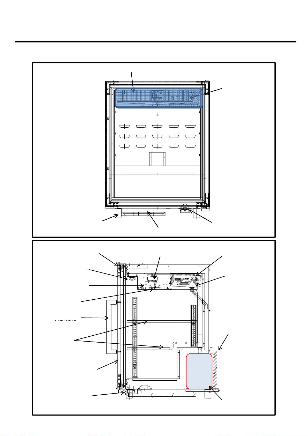
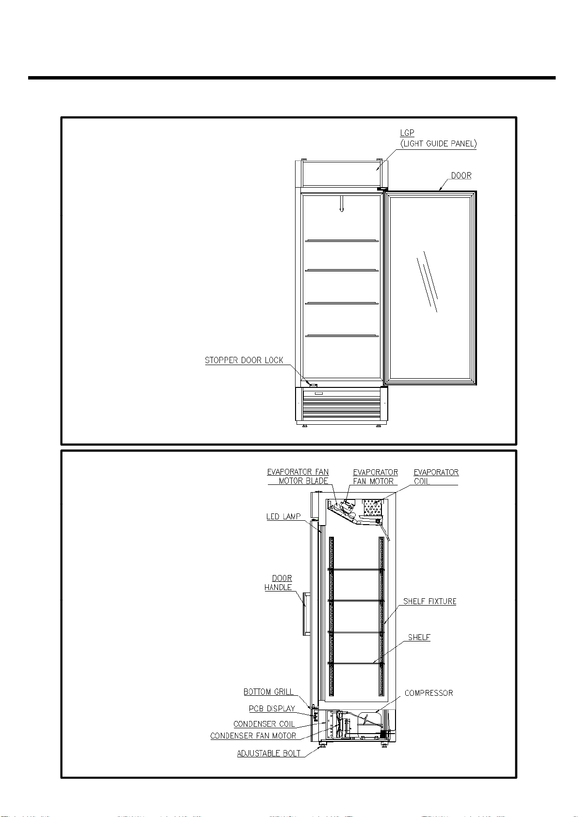
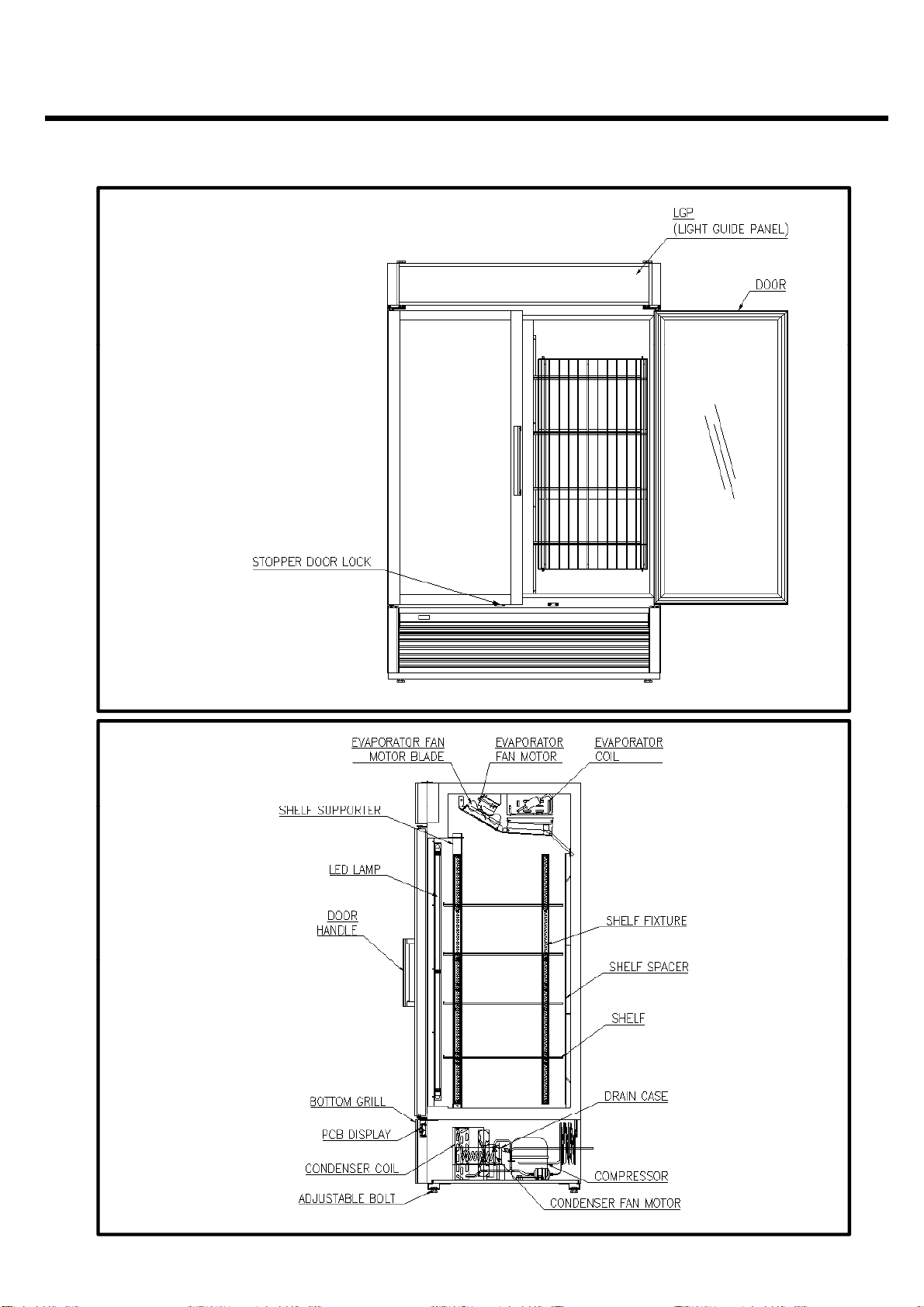
1. FEATURE CHART
amp
amp
Handle
Rear Cover
Door Assembly
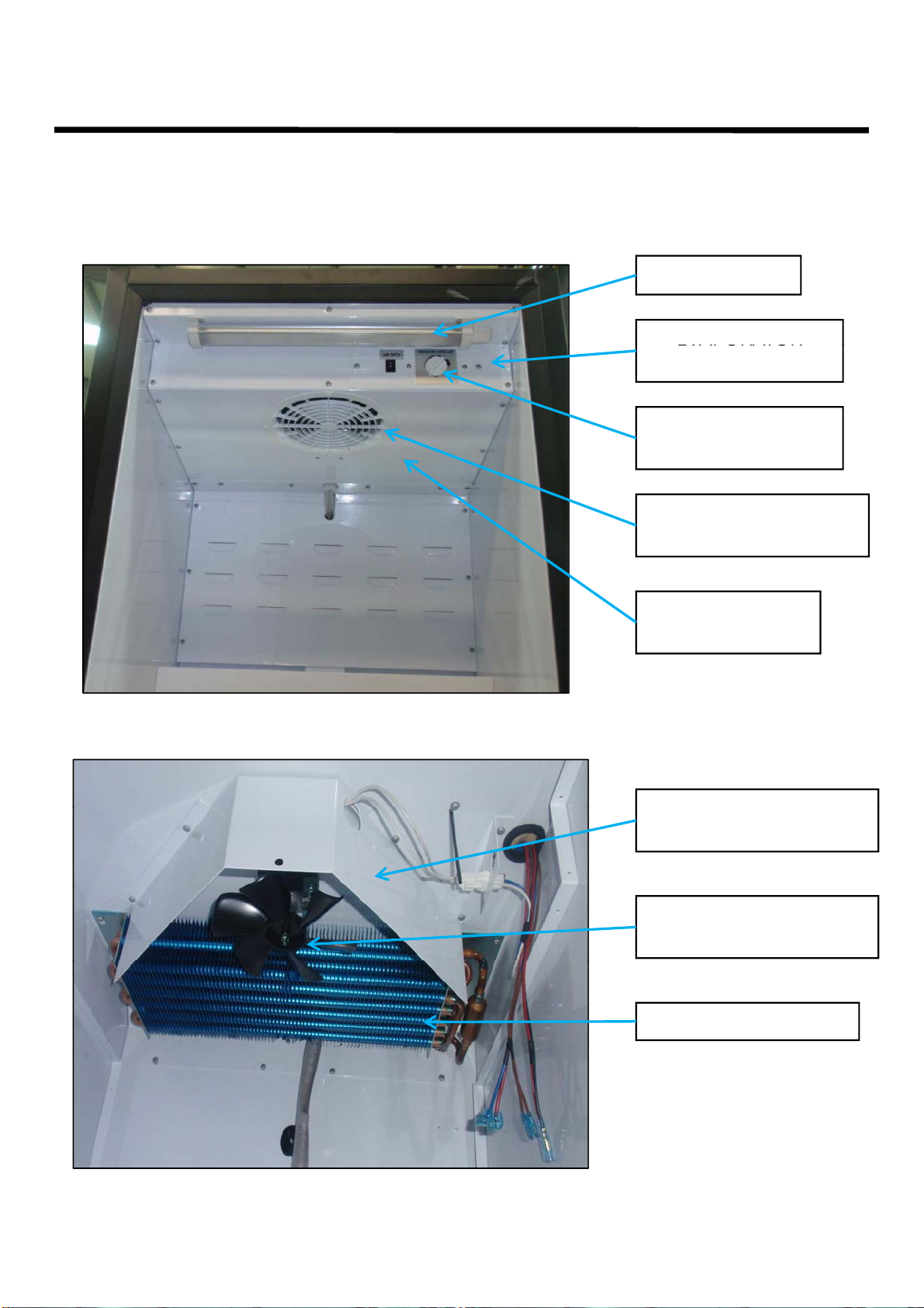
1-1. TGM-5SD*, TGM-7SD*, TGF-5SD*
<FRONT>
Evaporator Compartment
Control Panel
Adjustable Feet
<SIDE>
LED L
Fan Blade
Shroud
Shelf
Drain Case
Evaporator Fan MotorTop Hinge
Door Switch
Evaporator
Heater
(TGF-5SD*)
(Discharge
Ports)
Bottom Hinge Compressor
Compartment
Page 4
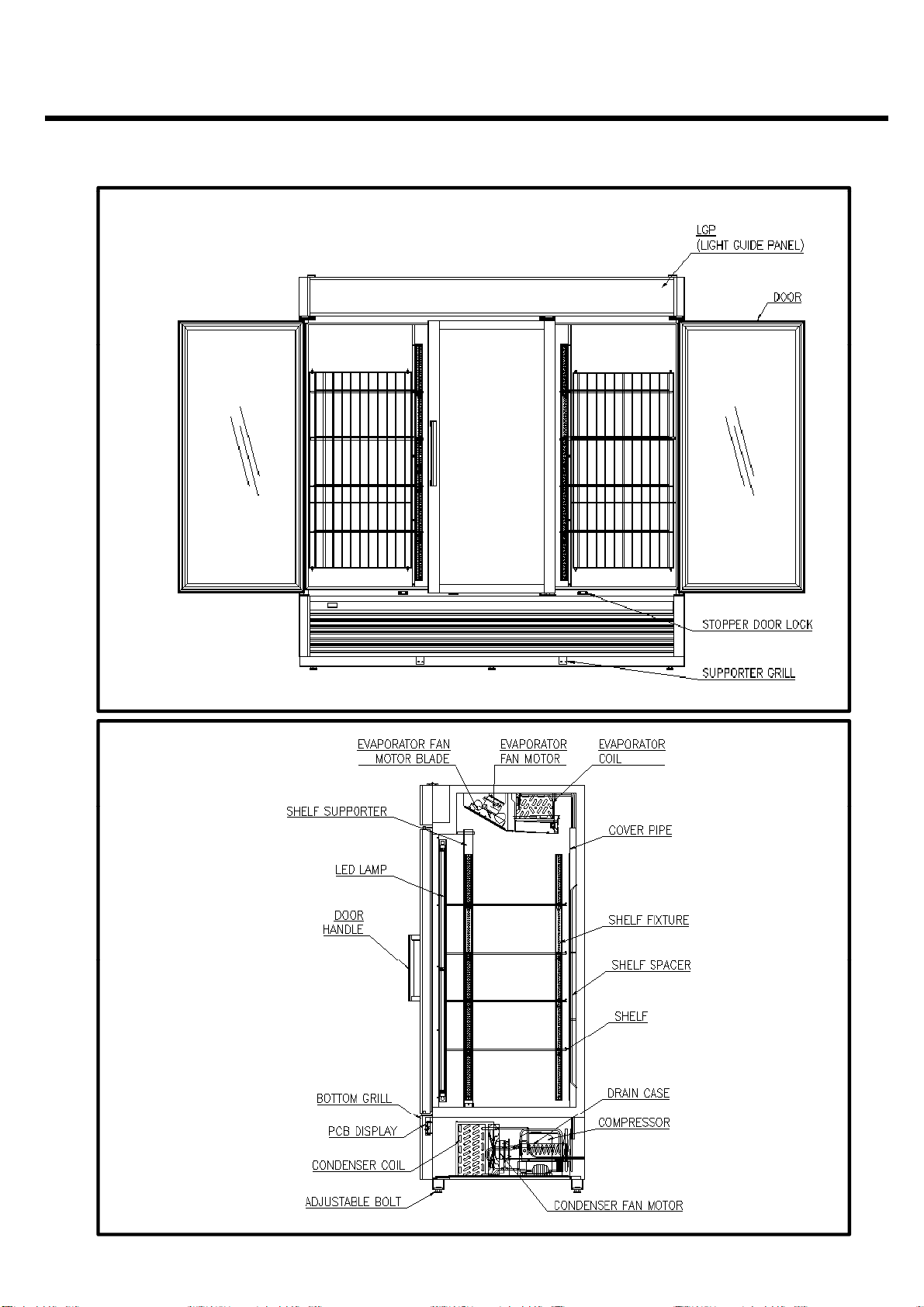
FEATURE CHART
Heater
Heater
1-2. TGM-10SD*, TGM-12SD*, TGF-10SD*
<FRONT>
Evaporator
Compartment
Temperature Display
(Control Panel)
Door Switch
Power Box
(PCB & Relay)
Drain Case
<SIDE>
LED Lamp
Fan Blade
Shroud
Handle
Door Assembly
Bottom Hinge
Top Hinge
Evaporator Fan Motor
Evaporator
(TGF-10SD*)
Shelf
Grille Assembly
Compressor
Compartment
Page 5
FEATURE CHART
1-3. TGM-15SD*, TGM-20SD*, TGM-23SD*, TGF-15SD*, TGF-23SD*
<FRONT>
<SIDE>
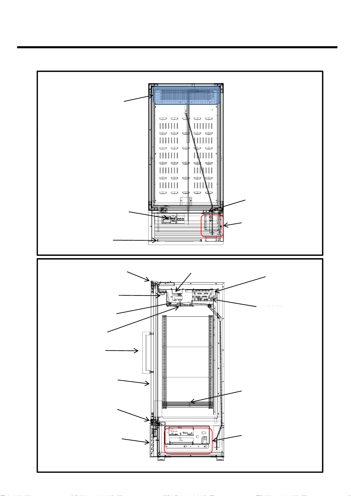
Page 6
FEATURE CHART
1-4. TGM-35SD*, TGM-47SD*, TGF-35SD*, TGF-47SD*
<FRONT>
<SIDE>
(TGF-47SD*)
Page 7
FEATURE CHART
1-5. TGM-72SD*, TGF-72SD*
<FRONT>
<SIDE>
(TGF-72SD*)
Page 8
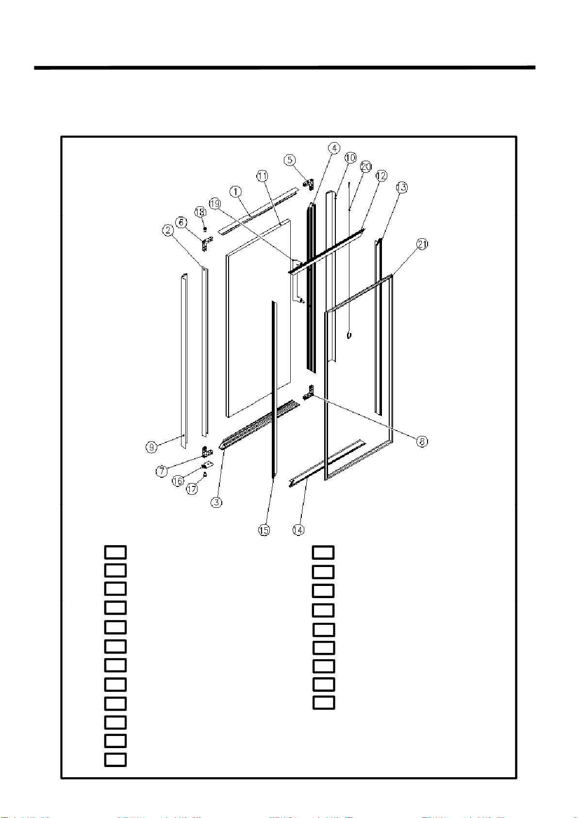
2. PART DETAILS
TGM
20SD*
TGM
23SD*, TGM
35SD*, TGM
47SD*, TGM
72SD
2-1. DOOR PARTS
2-1-1. TGM-5SD*, TGM-7SD*, TGM-10SD*, TGM-15SD*,
-
,
-
-
-
-
DOOR FRAME *TOP
01
02
DOOR FRAME *RIGHT
DOOR FRAME *BOTTOM
03
DOOR FRAME *LEFT
04
DOOR FRAME FIXTURE- A
05
DOOR FRAME FIXTURE- B
06
DOOR FRAME FIXTURE- B
07
DOOR FRAME FIXTURE- A
08
DOOR FRAME DECORATION * RIGHT
09
10
DOOR FRAME DECORATION * LEFT
DOOR GLASS
11
AUXILIARY DOOR FRAME * TOP
12
AUXILIARY DOOR FRAME * LEFT
13
AUXILIARY DOOR FRAME * BOTTOM
14
AUXILIARY DOOR FRAME * RIGHT
15
DOOR STOPPER (A) - RIGHT
16
17
DOOR BUSHING *BOTTOM
18
DOOR BUSHING *TOP
DOOR HANDLE
19
BAR SPRING
20
DOOR GASKET
21
Page 9
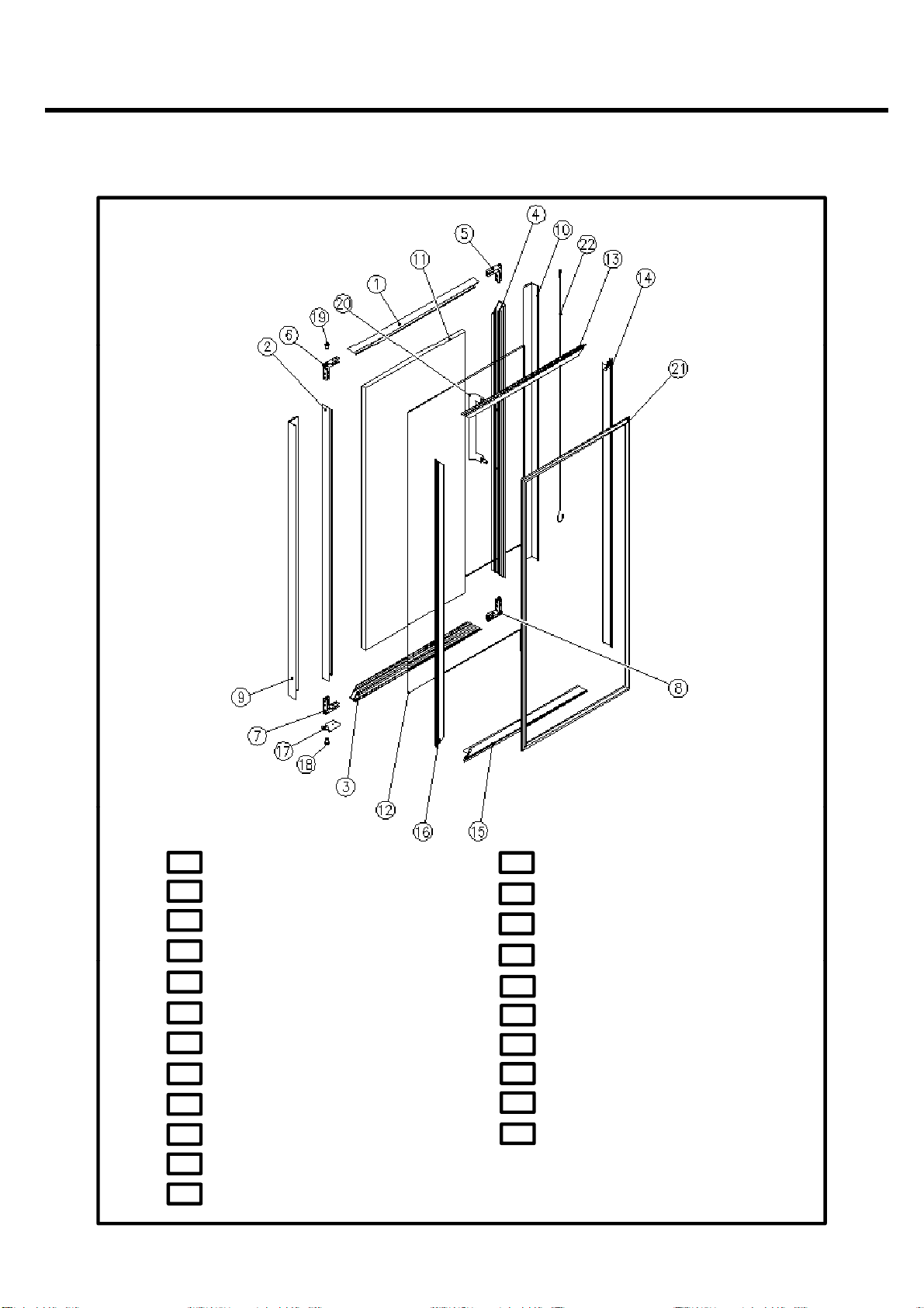
2. PART DETAILS
2-1-2. TGF-5SD, TGF-10SD, TGF-15SD*, TGF-23SD*
TGF-35SD*, TGF-47SD*, TGF-72SD
DOOR FRAME *TOP
01
DOOR FRAME *RIGHT
02
DOOR FRAME *BOTTOM
03
DOOR FRAME *LEFT
04
DOOR FRAME FIXTURE- A
05
DOOR FRAME FIXTURE- B
06
DOOR FRAME FIXTURE- B
07
08
DOOR FRAME FIXTURE- A
09
DOOR FRAME DECORATION * RIGHT
10
DOOR FRAME DECORATION * LEFT
DOOR GLASS
11
DOOR FRAME HEATER
12
13
AUXILIARY DOOR FRAME * TOP
AUXILIARY DOOR FRAME * LEFT
14
15
AUXILIARY DOOR FRAME * BOTTOM
AUXILIARY DOOR FRAME * RIGHT
16
DOOR STOPPER (A) - RIGHT
17
18
DOOR BUSHING *BOTTOM
19
DOOR BUSHING *TOP
20
DOOR HANDLE
21
BAR SPRING
22
DOOR GASKET
Page 10
PART DETAILS
■
2-2-1. TGM
5SD*, TGM
7SD*
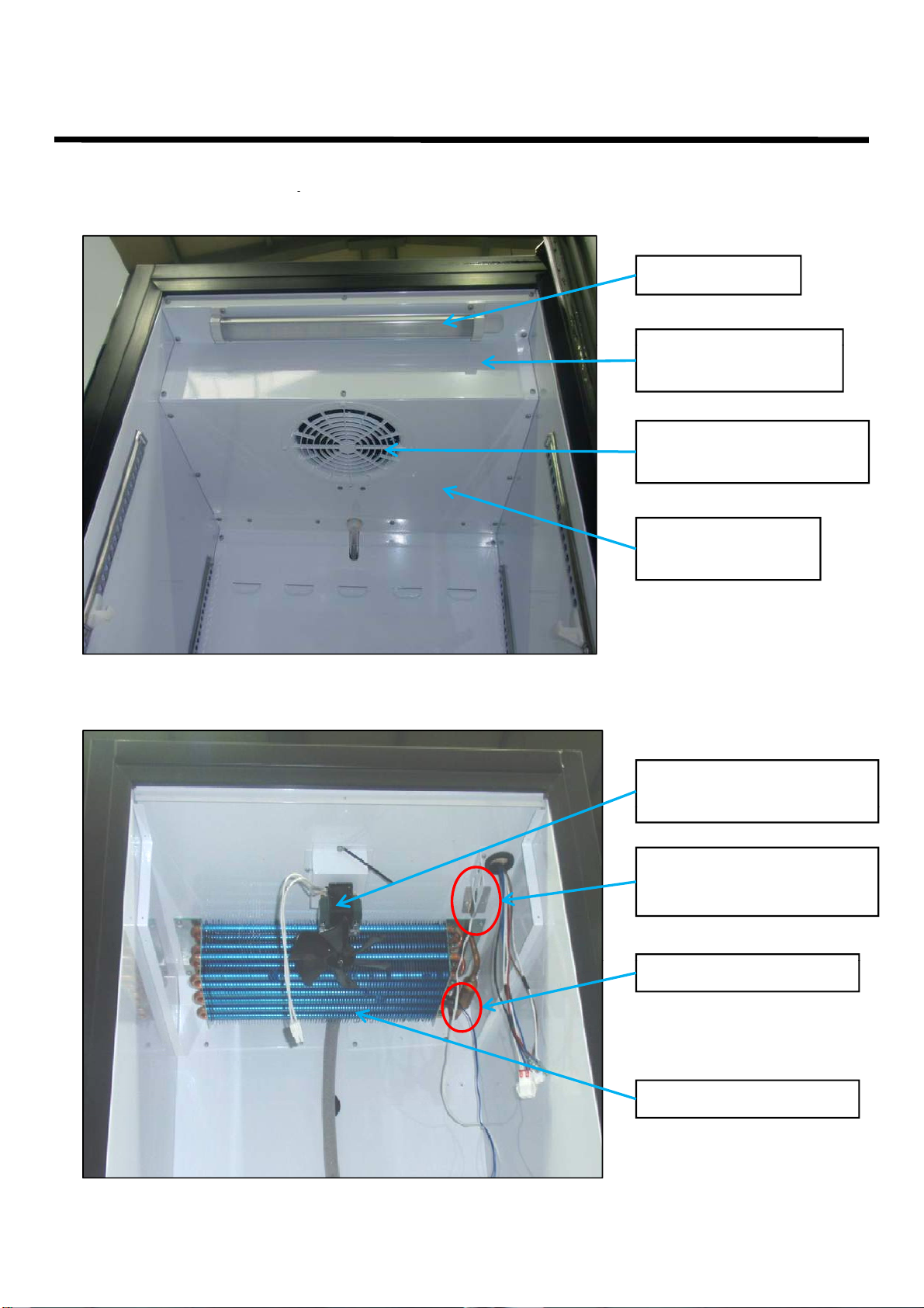
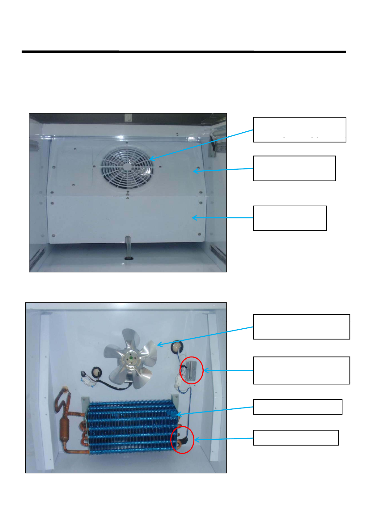
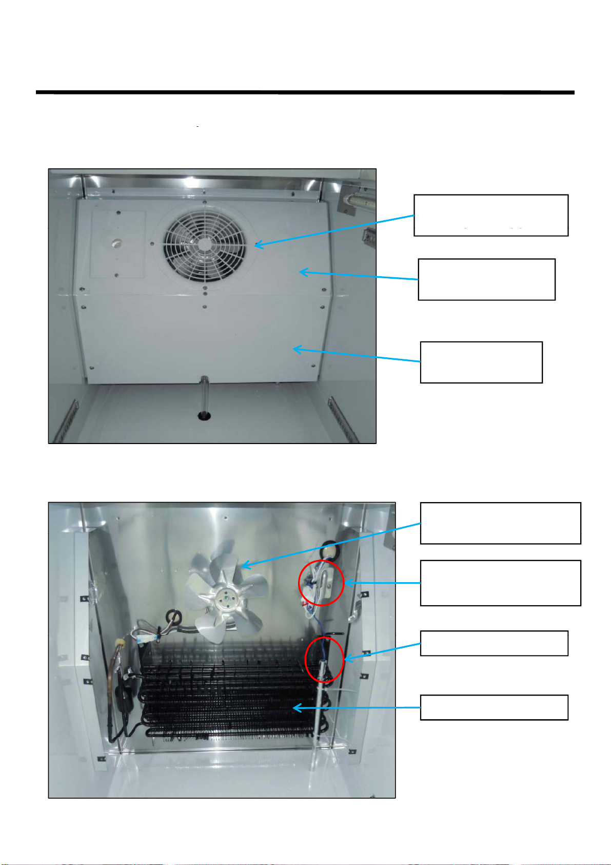
EVAPORATOR
EVAPORATOR
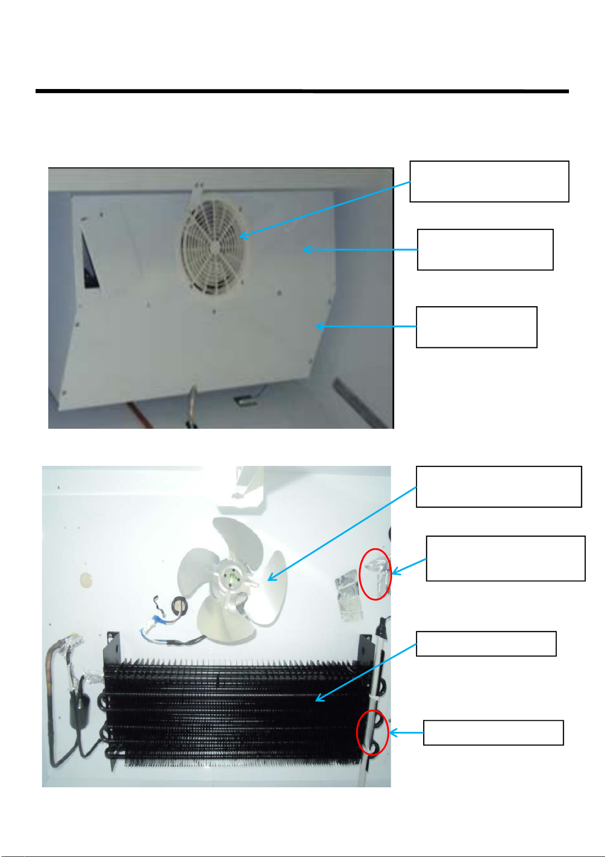
2-2. REFRIGERATION CYCLE
① DUCT
-
-
LED
FRONT COVER
TEMPERATURE
SENSOR
EVAPORATOR
FAN GRILLE GUARD
EVAPORATOR
BOTTOM COVER
② EVAPORATOR, FAN MOTOR, SENSORS
FAN MOTOR GUARD
EVAPORATOR
FAN MOTOR & BLADE
EVAPORATOR COIL
Page 11
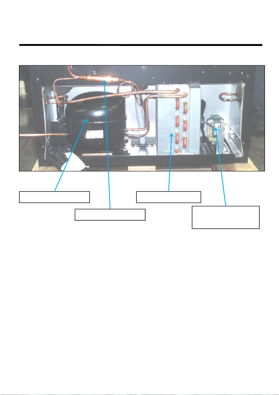
PART DETAILS
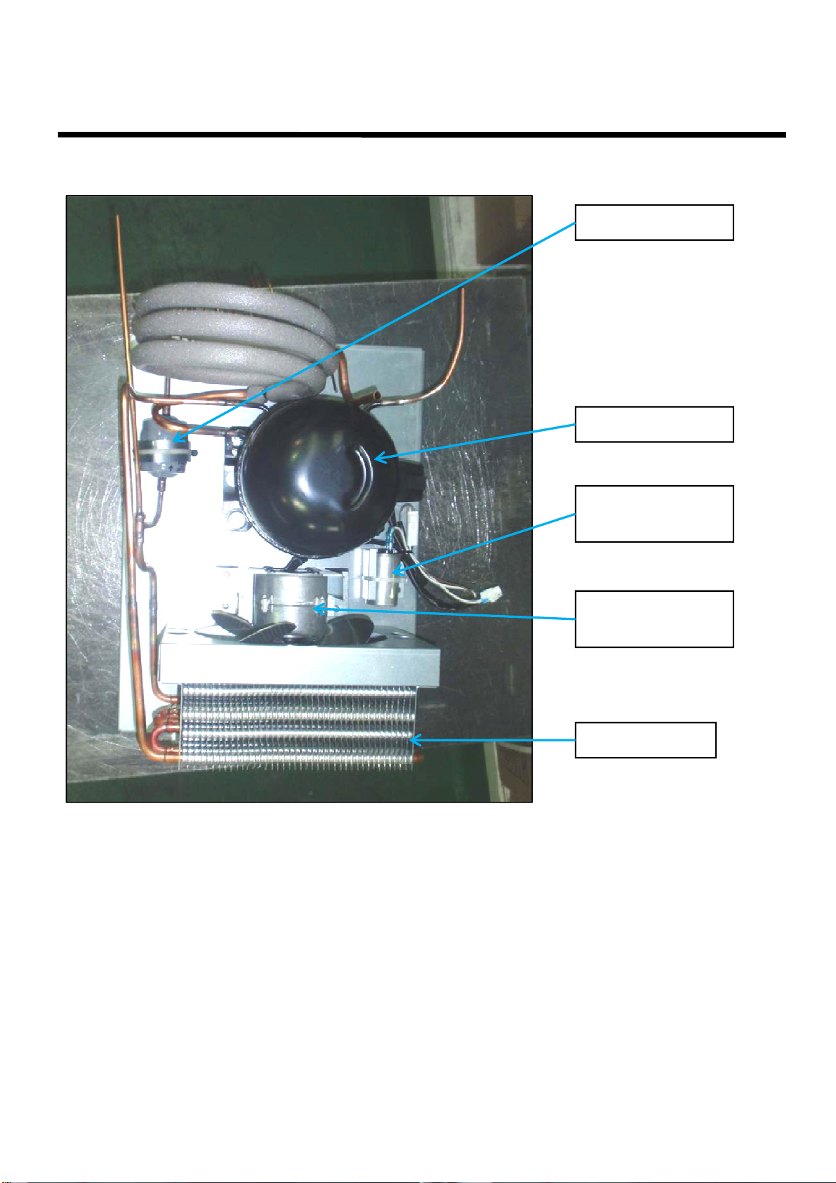
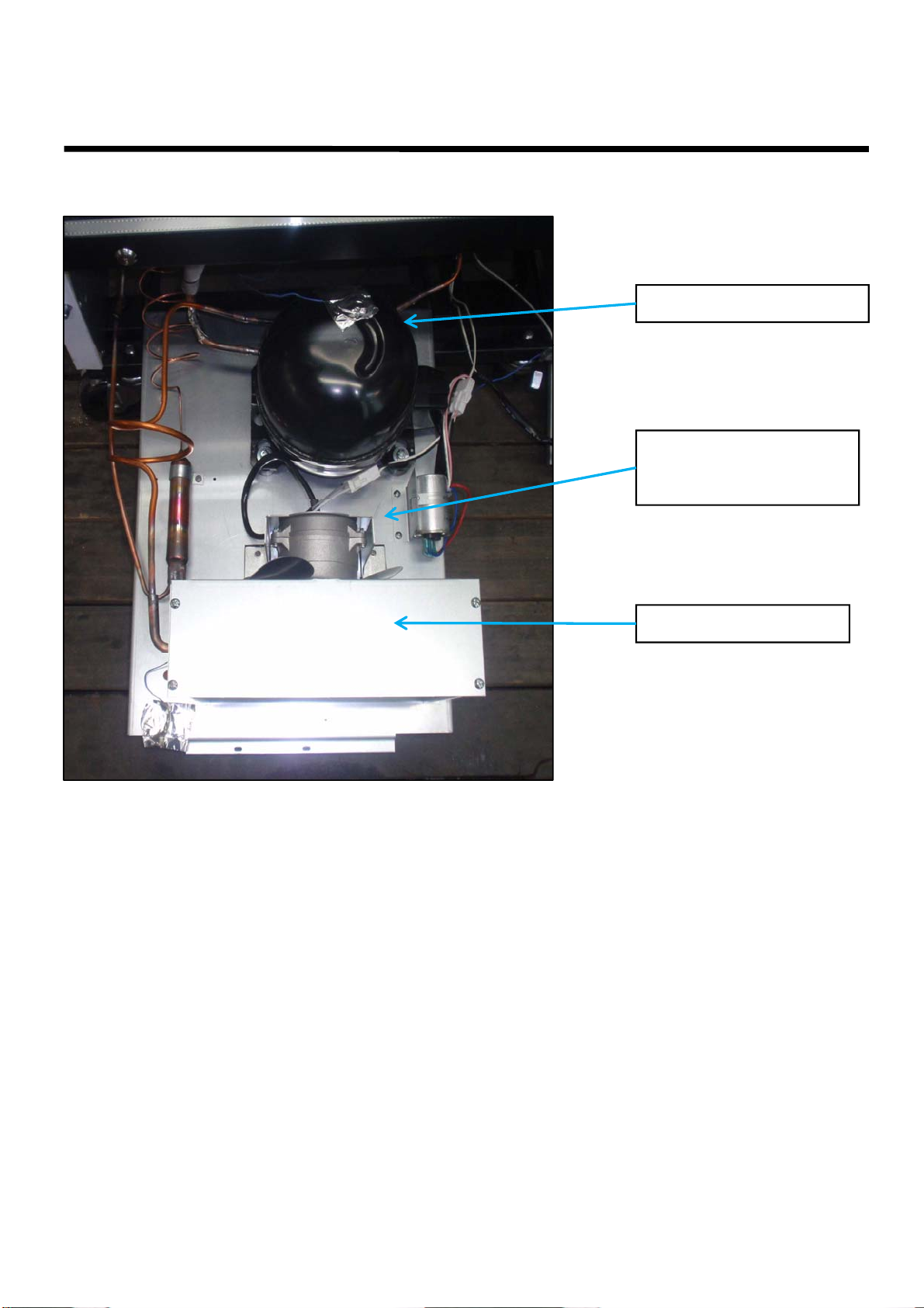
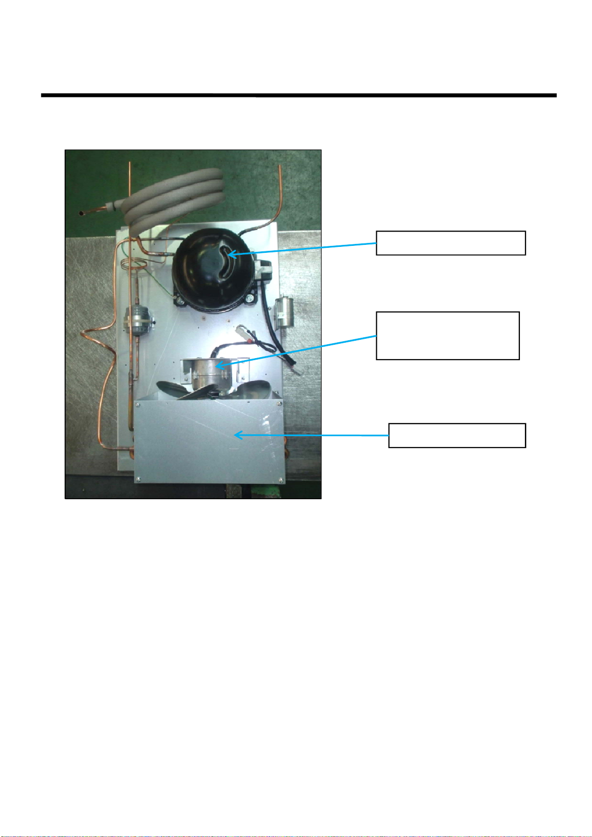
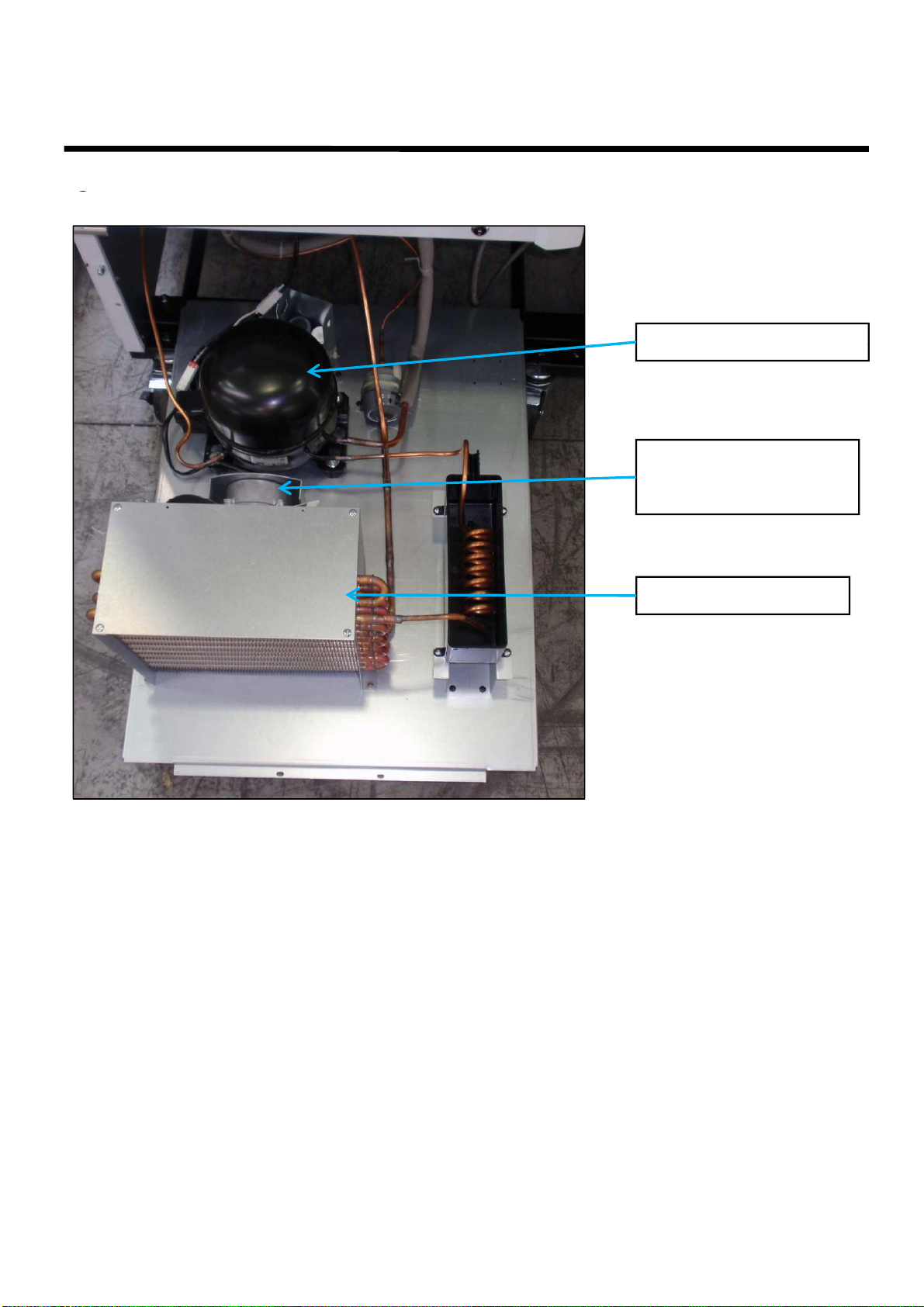
③
COMPRESSOR & FAN
MOTOR
COMPRESSOR
CONDENSER
DRYER
CONDENSER
FAN MOTOR
Page 12
PART DETAILS
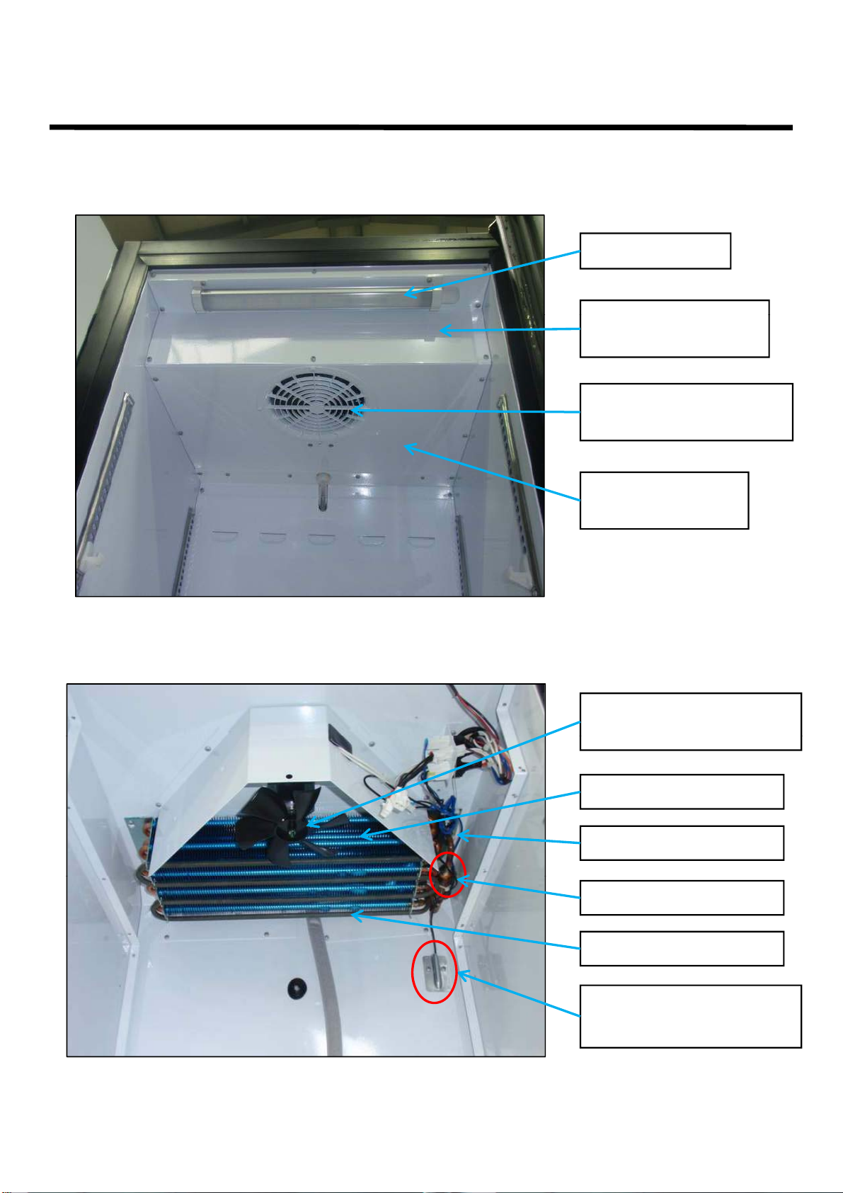
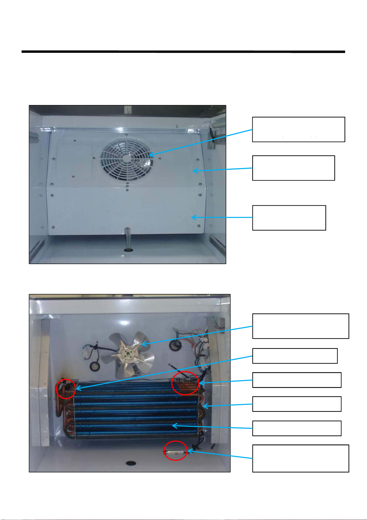
EVAPORATOR
EVAPORATOR
DEFROST SENSOR
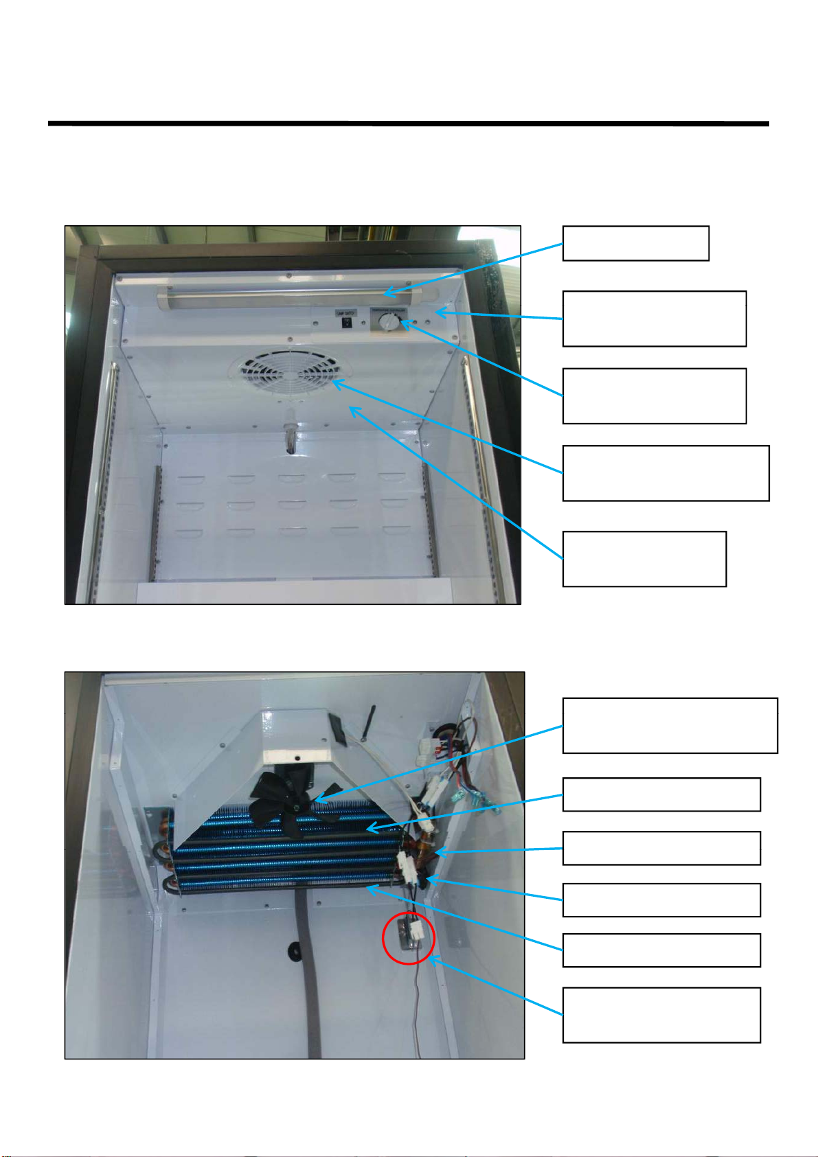
■ 2-2-2. TGF-5SD*
① DUCT
LED
FRONT COVER
TEMPERATURE
SENSOR
EVAPORATOR
FAN GRILLE GUARD
② EVAPORATOR, FAN MOTOR, SENSORS
EVAPORATOR
BOTTOM COVER
FAN MOTOR & BLADE
EVAPORATOR COIL
THERMAL FUSE
DEFROST HEATER
TEMPERATUE
SENSOR
Page 13
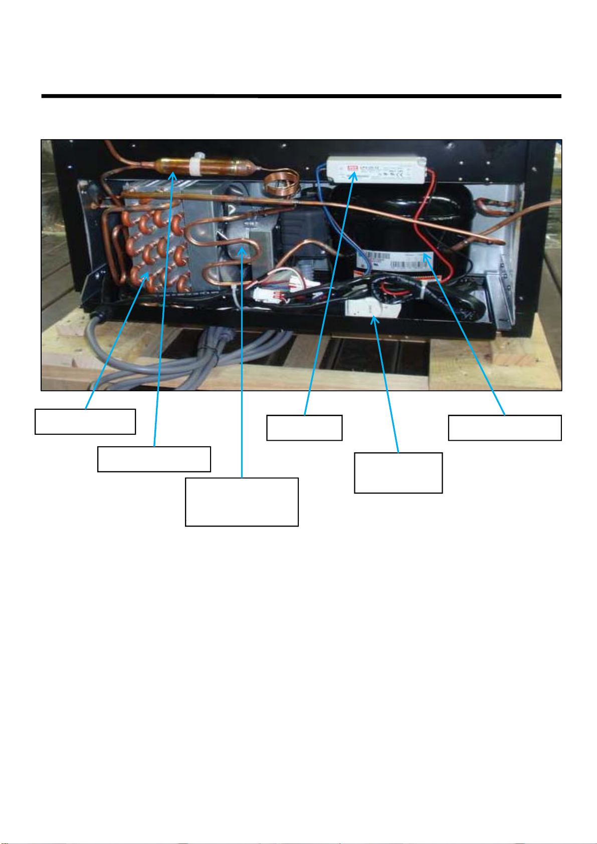
PART DETAILS
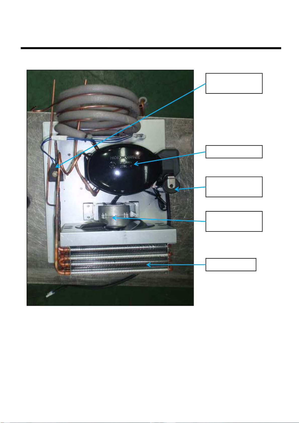
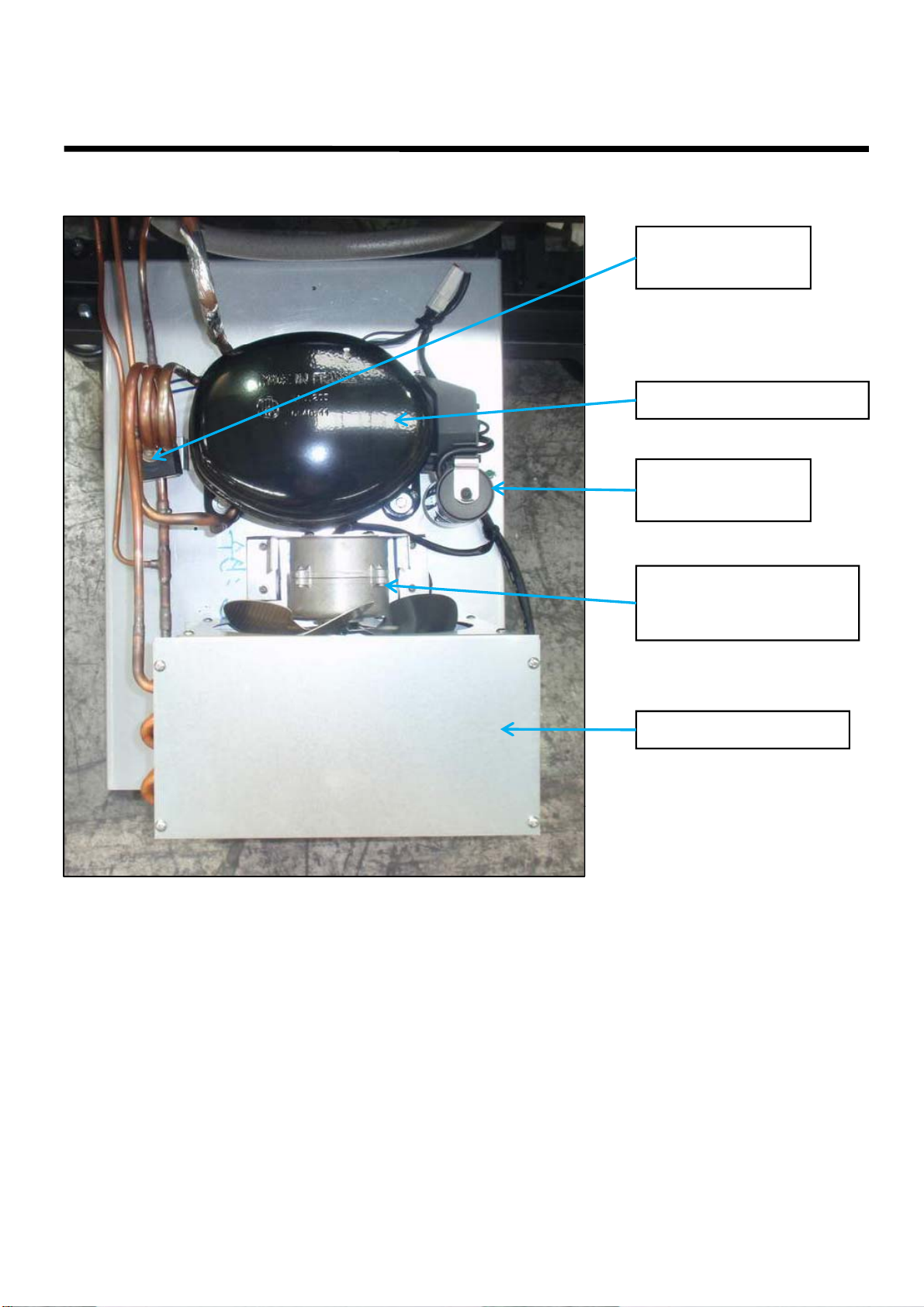
③
COMPRESSOR & FAN
MOTOR
CONDENSER
DRYER
CONDENSER
FAN MOTOR
SMPS
COMPRESSOR
DEFROST
TIMER
Page 14
PART DETAILS
,
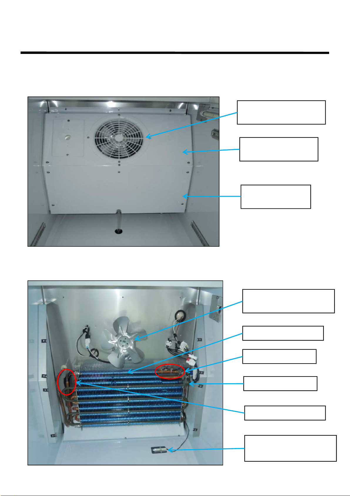
EVAPORATOR
FAN MOTOR & BLADE
■ 2-2-3. TGM-10SD*, TGM-12SD*
① DUCT
LED
FRONT COVER
EVAPORATOR
FAN GRILLE GUARD
EVAPORATOR
BOTTOM COVER
② EVAPORATOR, FAN MOTOR, SENSORS
EVAPORATOR
R-SENSOR
(TEMPERATURE CONTROL)
DEFROST SENSOR
EVAPORATOR COIL
Page 15
PART DETAILS
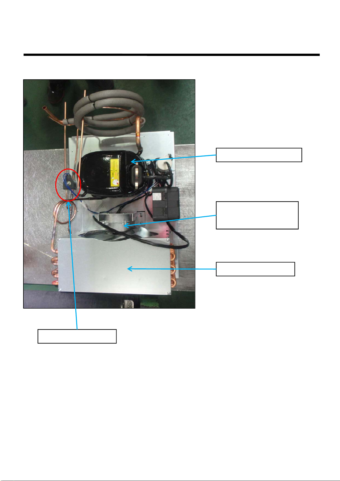
③
COMPRESSOR & FAN
MOTOR
DRYER
COMPRESSOR
RUNNING
CAPACITOR
CONDENSER
FAN MOTOR
CONDENSER
Page 16
PART DETAILS
EVAPORATOR
FAN MOTOR & BLADE
■ 2-2-4. TGF-10SD*
① DUCT
LED
FRONT COVER
EVAPORATOR
FAN GRILLE GUARD
EVAPORATOR
BOTTOM COVER
② EVAPORATOR, FAN MOTOR, SENSORS
EVAPORATOR
EVAPORATOR COIL
THERMAL FUSE
DEFROST SENSOR
DEFROST HEATER
R-SENSOR
(TEMPERATURE CONTROL)
Page 17
PART DETAILS
③
COMPRESSOR & FAN
MOTOR
SOLENOID
VALVE
COMPRESSOR
STARTING
CAPACITOR
CONDENSER
FAN MOTOR
CONDENSER
Page 18
PART DETAILS
G
■
2-2-5
TGM
-
15SD
FAN GRILLE GUARD
EVAPORATOR
① DUCT
*
EVAPORATOR
FAN
FRONT COVER
EVAPORATOR
BOTTOM COVER
RILLE GUARD
EVAPORATOR
② EVAPORATOR, FAN MOTOR, SENSORS
FAN MOTOR & BLADE
R-SENSOR
(TEMPERATURE CONTROL)
EVAPORATOR COIL
DEFROST SENSOR
Page 19
PART DETAILS
③
COMPRESSOR & FAN
MOTOR
COMPRESSOR
CONDENSER
FAN MOTOR
CONDENSER
Page 20
PART DETAILS
G
■
2-2-6.TGF
-
15SD
FAN GRILLE GUARD
EVAPORATOR
THERMAL FUSE
① DUCT
*
EVAPORATOR
FAN
FRONT COVER
EVAPORATOR
BOTTOM COVER
RILLE GUARD
EVAPORATOR
② EVAPORATOR, FAN MOTOR, SENSORS
FAN MOTOR & BLADE
DEFROST SENSOR
DEFROST HEATER
EVAPORATOR COIL
R-SENSOR
(TEMPERATURE CONTROL)
Page 21
PART DETAILS
③
COMPRESSOR & FAN
MOTOR
CAPACITOR
SOLENOID
VALVE
COMPRESSOR
STARTING
CONDENSER
FAN MOTOR
CONDENSER
Page 22
PART DETAILS
G
,
FAN GRILLE GUARD
FAN MOTOR & BLADE
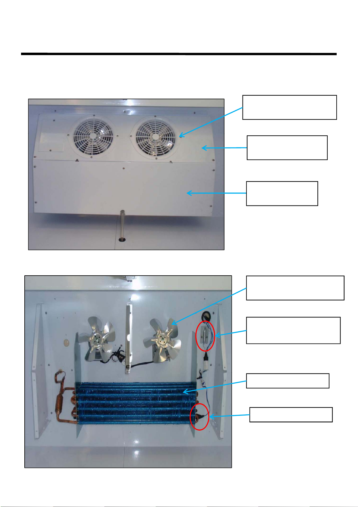
■ 2-2-7. TGM-20SD*, TGM-23SD*
① DUCT
EVAPORATOR
FAN
BOTTOM COVER
RILLE GUARD
EVAPORATOR
FRONT COVER
EVAPORATOR
② EVAPORATOR, FAN MOTOR, SENSORS
EVAPORATOR
R-SENSOR
(TEMPERATURE CONTROL)
DEFROST SENSOR
EVAPORATOR COIL
Page 23
PART DETAILS
CONDENSER
③ COMPRESSOR & FAN MOTOR
COMPRESSOR
FAN MOTOR
CONDENSER
Page 24
PART DETAILS
EVAPORATOR
FAN MOTOR & BLADE
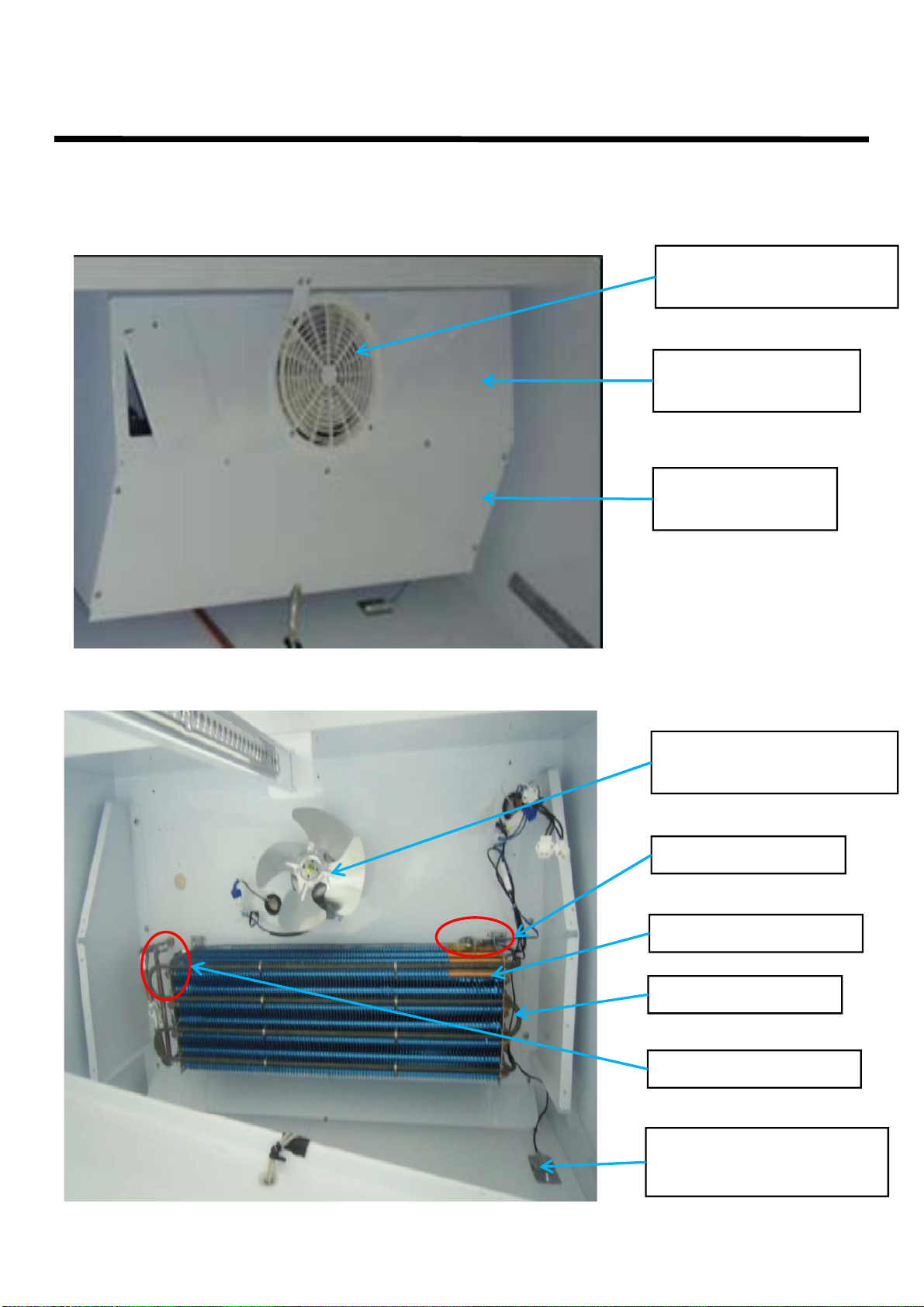
■ 2-2-8. TGF-23SD*
① DUCT
EVAPORATOR
FAN GRILLE GUARD
EVAPORATOR
FRONT COVER
BOTTOM COVER
② EVAPORATOR, FAN MOTOR, DEFROST HEATER, SENSORS
EVAPORATOR
EVAPORATOR COIL
THERMAL FUSE
DEFROST HEATER
DEFROST SENSOR
F-SENSOR
(TEMPERATURE CONTROL)
Page 25
PART DETAILS
③
COMPRESSOR & FAN
MOTOR
COMPRESSOR
CONDENSER
SOLENOID VALVE
FAN MOTOR
CONDENSER
Page 26
PART DETAILS
DEFROST SENSOR
■ 2-2-9. TGM-35SD*, TGM-47SD*
① DUCT(TGM-35SD*)
EVAPORATOR
FAN GRILLE GUARD
EVAPORATOR
FRONT COVER
EVAPORATOR
BOTTOM COVER
② EVAPORATOR, FAN MOTOR, SENSORS(TGM-35SD*)
EVAPORATOR
FAN MOTOR & BLADE
R-SENSOR
(TEMPERATURE CONTROL)
EVAPORATOR COIL
Page 27
PART DETAILS
■ 2-2-9. TGM-35SD*, TGM-47SD*
① DUCT(TGM-47SD*)
EVAPORATOR
FAN GRILLE GUARD
EVAPORATOR
FRONT COVER
EVAPORATOR
BOTTOM COVER
② EVAPORATOR, FAN MOTOR, SENSORS(TGM-47SD*)
EVAPORATOR
FAN MOTOR & BLADE
R-SENSOR
(TEMPERATURE CONTROL)
EVAPORATOR COIL
DEFROST SENSOR
Page 28
PART DETAILS
③
COMPRESSOR
FAN MOTOR
COMPRESSOR & FAN MOTOR(TGM-35SD*, TGM-47SD*)
CONDENSER
CONDENSER
Page 29
PART DETAILS
■ 2-2-10. TGF-35SD*, TGF-47SD*
① DUCT(TGF-35SD*)
EVAPORATOR
FAN GRILLE GUARD
EVAPORATOR
FRONT COVER
EVAPORATOR
BOTTOM COVER
② EVAPORATOR, FAN MOTOR, DEFROST HEATER, SENSORS(TGF-35SD*)
EVAPORATOR
FAN MOTOR & BLADE
THERMAL FUSE
EVAPORATOR COIL
DEFROST HEATER
DEFROST SENSOR
F-SENSOR
(TEMPERATURE CONTROL)
Page 30

PART DETAILS
■ 2-2-10. TGF-35SD*, TGF-47SD*
① DUCT(TGF-47SD*)
EVAPORATOR
FAN GRILLE GUARD
EVAPORATOR
FRONT COVER
EVAPORATOR
BOTTOM COVER
② EVAPORATOR, FAN MOTOR, DEFROST HEATER, SENSORS(TGF-47SD*)
EVAPORATOR
FAN MOTOR & BLADE
THERMAL FUSE
EVAPORATOR COIL
DEFROST HEATER
DEFROST SENSOR
F-SENSOR
(TEMPERATURE CONTROL)
Page 31

PART DETAILS
③
COMPRESSOR & FAN
MOTOR(TGF
35SD, TGF
47SD )
COMPRESSOR
-
*
-
*
CONDENSER
FAN MOTOR
CONDENSER
Page 32

PART DETAILS
②
EVAPORATOR, FAN MOTOR
SENSORS
■ 2-2-11. TGM-72SD*
① DUCT
EVAPORATOR
FAN GRILLE GUARD
EVAPORATOR
FRONT COVER
EVAPORATOR
BOTTOM COVER
EVAPORATOR COIL
,
R-SENSOR
(TEMPERATURE CONTROL)
EVAPORATOR
FAN MOTOR & BLADE
DEFROST SENSOR
Page 33

PART DETAILS
③
COMPRESSOR & FAN
MOTOR
COMPRESSOR
CONDENSER
FAN MOTOR
CONDENSER
Page 34

PART DETAILS
F-SENSOR
■ 2-2-12. TGF-72SD*
① DUCT
② EVAPORATOR, FAN MOTOR, DEFROST HEATER, SENSORS
EVAPORATOR
FAN GRILLE GUARD
EVAPORATOR
FRONT COVER
EVAPORATOR
BOTTOM COVER
EVAPORATOR COIL
DEFROST HEATER
DEFROST SENSOR
EVAPORATOR
FAN MOTOR & BLADE
(TEMPERATURE CONTROL)
THERMAL
FUSE
Page 35

PART DETAILS
③
COMPRESSOR & FAN
MOTOR
CONDENSER
CONDENSER
FAN MOTOR
COMPRESSOR
Page 36

3. WIRING DIAGRAM
3-1. TGM-5SD*, TGM-7SD*
3-2. TGF-5SD*
Page 37

3-3. TGM-10SD*, TGM-12SD*
WIRING DIAGRAM
Page 38

3-4. TGF-10SD*
WIRING DIAGRAM
Page 39

3-5. TGM-15SD*, TGM-20SD*, TGM-23SD*
WIRING DIAGRAM
Page 40

3-6. TGF-15SD*, TGF-23SD*
WIRING DIAGRAM
Page 41

3-6. TGF-15SD*, TGF-23SD*
WIRING DIAGRAM
WIRING DIAGRAM
Page 42

3
7. TGM
35SD
-
-
*
Page 43

WIRING DIAGRAM
3
8. TGF
35SD
-
-
*
Page 44

WIRING DIAGRAM
3
9. TGM
47SD
-
-
*
Page 45

3-10. TGF-47SD*
WIRING DIAGRAM
Page 46

3-11. TGM-72SD*
WIRING DIAGRAM
Page 47

WIRING DIAGRAM
3
12. TGF
72SD
-
-
*
Page 48

4.
R
,
,
(
)
()
,
,/
SPECIFICATION OF MAIN COMPONENTS
4-1. COMPRESSO
MODEL PART NAME PART NO.
TGM-5SD*
TGM-7SD*
TGF-5SD*
TGM-10SD*
TGM-12SD*
TGM-15SD*
TGM-20SD*
TGM-23SD*
TGM-35SD*
TGM-47SD*
TGM-72SD* T6217Z 3020014570 2/3 HP
TGF-5SD* AEZ2415Z 30200N4400 1/3 HP
TGF-10SD*
TGF-15SD*
MSA151D-L1B P0189A0100 1/6 HP
MK183D-L2UB 30289R0100 1/4 HP 1.98A SAMSUNG
SK1A1C-L2W 30200Q1200 1/3 HP
CAE2420Z 30200R1100 1/2 HP
HORSE
POWER MOTOR (RLA) Hz
CAPACITY
603 BTU/h LBP
(152 Kcal/h) RSCR
1,203 BTU/h LBP
(303 Kcal/h) CSR
1,203 BTU/h LBP
(303 Kcal/h) CSR 60Hz
638 BTU/h HBP 115V
7
(1,925 Kcal/h) CSIR 60Hz
1,459 BTU/h LBP
(368 Kcal/h) CSIR 60Hz
2,268 BTU/h LBP
572 Kcal/h
TYPE OF Current Voltage
1.03A
3.85A
10.48A EMBRACO
4.5A
6.6A
CSIR 60Hz
115V
60Hz
115V
60Hz
115V
115V
115V
MAKER
SAMSUNG
SAMSUNG
TECUMSEH
TECUMSEH
TGF-23SD* CAJ2432Z 30200R1000 2/3 HP
TGF-35SD* NJ2192GK P0189A0200 1 1/4HP
TGF-47SD* 4
CAJ2446Z 30200Q3600 1 HP
TGF-72SD* (1,213 Kcal/h) CSR 60Hz
3,200 BTU/h LBP
7.0A
(807 Kcal/h) CSR 60Hz
4,500 BTU/h LBP
4.8A
(1,134 Kcal/h) CSR 60Hz
800 BTU/hLBP 220V
4.8A TECUMSEH
115V
115V
4-2. COMPRESSOR RELAY & OVERLOAD PROTECTOR
COMPRESSOR RELAY PART NO. OVERLOAD PART NO. MAKER NOTE
MSA151D-L1B 100MD2 - SM308RHB-U1 - SAMSUNG
MK183D-L2UB 6R8MD2 - 4TM-445PHBZZ - SAMSUNG
SK1A1C-L2W 22Ω-3PIN - 4TM-795TFBZZ - SAMSUNG
T6217Z 9660C-3027 - MRT00AF - EMBRACO
AEZ2415Z KPF479 - AE85FLY* - TECUMSEH
CAE2420Z 3ARR12 - T0889 - TECUMSEH
TECUMSEH
EMBRACO
CAJ2432Z 3ARR3*5** - GA3PJU00 -TECUMSEH
NJ2192GK 3ARR3B3P3 - 15HM2442-168 -EMBRACO
CAJ2446Z MST00AHZ - MST00AHZ or T0594 -TECUMSEH
Page 49

MAIN COMPONENTS
TGF-72SD
250V/88
㎌-400V/15
㎌-TECUMSEH
DAI-6202DWSUA
P0191A0200
1EA
ZITEL 3
150mm
DAI-YOUNG
TGF
15SD
TGF-35SD*
DAI-8204DWSUA
P0191Q0200
2EA
AL 4
225mm
4-3. COMPRESSOR CAPACITOR
MODEL STARTING PART NO. RUNNING PART NO. MAKER NOTE
TGM-5SD*
TGM-7SD*
TGM-10SD*
TGM-12SD*
TGM-15SD*
TGM-20SD*
TGM-23SD*
TGM-35SD*
TGM-47SD*
TGM-72SD 330V/189-227㎌ - - - EMBRACO
TGF-5SD* 160V/250㎌ - - - TECUMSEH
TGF-10SD*
TGF-15SD*
TGF-23SD* 160V/315㎌ - 400V/30㎌ -TECUMSEH
TGF-35SD* 125V/400㎌ 440V/20㎌ EMBRACO
TGF-47SD* 330V/125㎌ - 400V/20㎌ -EMBRACO
*
- - 250V/12㎌ - SAMSUNG
- - 250V/12㎌ - SAMSUNG
125V/125㎌ 30264L0200 250V/12㎌ 30264L0100 SAMSUNG
160V/315㎌ - - - TECUMSEH
4-4. CONDENSER FAN MOTOR
MODEL PART NAME PART NO. Quantity BLADE SIZE MAKER
TGM-5SD*
TGM-7SD*
TGF-5SD* DAI-8204DWSUA P0191Q0200 1EA AL 5 175mm DAI-YOUNG
TGM-10SD*
TGM-12SD*
TGM-15SD*
TGF-10SD*
-
*
TGM-23SD*
TGF-23SD*
TGM-47SD*
TGM-72SD*
TGM-35SD* DAI-8204DWSUA P0191Q0200 1EA AL 4 225mm
TGF-47SD* DAI-8204DWSQ-1 3963336200 2EA AL 4 225mm
TGF-72SD* DAI-8204DWSQ-1 3963336200 2EA AL 4 250mm
DAI-8204DWSUA P0191Q0200 1EA AL 4 200mm
DAI-YOUNG
DAI-8204DWSUA P0191Q0200 1EA AL 4 250mm
DAI-YOUNG
Page 50

MAIN COMPONENTS
MODEL
PART NAME
PART NO
Quantity
BLADE
SIZE
MAKER
P0128U0200
200W
1EA
4-5. EVAPORATOR FAN MOTOR
TGM-5SD*
TGM-7SD*
TGF-5SD*
TGM-10SD*
TGM-12SD*
TGM-15SD*
TGM-20SD*
TGM-23SD*
TGF-10SD*
TGF-15SD*
TGF-23SD*
DAI-6202DWSUA-1 P0191A0100 1EA ZITEL 6 150mm DAI-YOUNG
DAI-8154DWSUA P0191Q0100 1EA AL 5 175mm DAI-YOUNG
.
TGM-35SD*
TGF-35SD*
TGM-47SD*
TGM-72SD*
TGF-47SD*
TGF-72SD* DAI-8154DWSUA P0191Q0100 2EA AL 4 200mm DAI-YOUNG
DAI-8154DWSUA P0191Q0100 1EA AL4 200mm DAI-YOUNG
DAI-8154DWSUA P0191Q0100 2EA AL 5 175mm DAI-YOUNG
4-6. EVAPORATOR DEFROST HEATER
MODEL PART NAME PART NO. SPEC Quantity MAKER
TGF-5SD* P0128U0100 200W 1EA
TGF-10SD*
TGF-15SD*
SHEATH HEATER SANG-DO
TGF-23SD* 30228L0803 445W 1EA
TGF-35SD*
TGF-47SD*
TGF-72SD* 30228L00701 600W 2EA
30228L00701 600W 1EA
Page 51

MAIN COMPONENTS
TGM
12SD
INTERIOR
TGF
35SD*
INTERIOR
LED
19W-12V
30236R2200
4
4-7. SMPS
MODEL APPLICATION PART NAME SPEC PART NO. QTY MAKER
TGM-5SD*
TGM-7SD*
TGF-5SD*
TGM-10SD*
TGM-15SD*
TGM-20SD*
TGM-23SD*
TGF-10SD*
TGF-15SD*
TGF-23SD*
*
INTERIOR SMPS LPV-20-12(12V) 30284R0500 1 MEAN WELL
SMPS SM40W115 30284R1100 1 NEUROSYS
SIGN PANEL
TGM-35SD*
-
TGM-47SD*
TGF-47SD*
TGM-72SD*
TGF-72SD*
INTERIOR SMPS LPV-60-12(12V) 30284R0700 1 MEAN WELL
SIGN PANEL SMPS SM40W115 30284R1100 1 NEUROSYS
INTERIOR SMPS LPV-60-12(12V) 30284R0700 2 MEAN WELL
SIGN PANEL SMPS SM40W115 30284R1100 1 NEUROSYS
4-8. LED & LIGHT GUIDE PANEL
MODEL APPLICATION PART NAME SPEC PART NO. QTY BULB
TGM-5SD*
TGM-7SD*
TGF-5SD*
TGM-10SD*
TGM-12SD*
TGF-10SD*
TGM-15SD*
TGM-20SD*
TGM-23SD*
TGF-23SD*
INTERIOR LED 10W-12V P0136A0101 1 -
INTERIOR LED 14W-12V P0136A0100 1 -
INTERIOR LED 19W-12V 30236R2200 1 -
SIGN PANEL LIGHT GUIDE PANEL 8.28W-12V P0142U4000 1 -
INTERIOR LED 19W-12V 30236R2200 1 -
SIGN PANEL LIGHT GUIDE PANEL 8.64W-12V P0142U4100 1 -
TGM-35SD*
TGF-35SD*
TGM-47SD*
TGF-47SD*
TGM-72SD*
TGF-72SD*
INTERIOR LED 19W-12V 30236R2200 2 -
SIGN PANEL LIGHT GUIDE PANEL 16.44W-12V P0142U4200 1 -
INTERIOR LED 19W-12V 30236R2200 2 -
SIGN PANEL LIGHT GUIDE PANEL 16.44W-12V P0142U4300 1 -
-
SIGN PANEL LIGHT GUIDE PANEL 25.68W-12V P0142U4400 1 -
Page 52

MAIN COMPONENTS
4-9. POWER SWITCH & LAMP SWITCH
G
G
S
TGM
47SD
MODEL SPEC PART NO. QTY MAKER
TGM-5SD*
TGM-7SD*
TGM-10SD*
TGM-12SD*
F-5SD*
T
TGF-10SD
TGM-15SD*
TGM-20SD*
TGM-23SD*
TGF-23SD*
TGM-35SD*
TGF-35SD*
TGF-47SD*
TGM-72SD*
TGF-72SD*
*
POWER
R19A(RA15) 30281Q0101
INTERIOR 1
POWER
INTERIOR 1
SIGN PANEL 1
R19A(RA15) 30281Q0101
1
1
LIGHT CONTRY
4-10. DOOR SWITCH
MODEL PART NAME SPEC PART NO. QTY MAKER
TGM-5SD*
TGM-7SD*
TGM-10SD*
TGM-12SD*
TGF-5SD*
TGF-10SD*
TGM-15SD*
TGM-20SD*
TGM-23SD*
TGF-23SD*
TGM-35SD*
TGF-35SD*
TGM-47SD*
TGF-47SD*
TGM-72SD*
TGF-72SD*
DOOR SWITCH DSD-6 P0181L0200 1 DAE-HAN
DOOR SWITCH E31001CA 30281R0101 1
ARCOLETRIC
DOOR SWITCH E31001CA 30281R0101 2
DOOR SWITCH E31001CA 30281R0101 3
Page 53

MAIN COMPONENTS
TGM
35SD
4-11. MAIN PCB
MODEL PART NAME SPEC PART NO. MAKER
TGM-10SD*
TGF-12SD*
TGM-15SD*
TGM-23SD*
-
*
TGM-47SD*
TGM-72SD*
TGM-35SD*
TGF-10SD* MAIN PCB SGFF1152 30243R1300
TGF-23SD*
TGF-35SD* MAIN PCB GFF1152 30243R0700
TGF-47SD*
TGF-72SD*
TGF-35SD*
MAIN PCB SGRF1153 30243R1200
MAIN PCB GRF1152 30243R0600
MAIN PCB 2GFF1152 P0143K0100
NEUROSYS
Page 54

5.
5-1
SD REFRIGERATOR CONTROLLER
(
(
)()y
MAIN PCB PROGRAMING
▶ TGM-10SD*, TGM-12SD*, TGM-15SD*, TGM-20SD*,
TGM-23SD*, TGM-35SD*, TGM-47SD*, TGM-72SD*
5-1-1. HOW TO USE THE DISPLAY PANEL
- The default temperature setting is 37℉.
- The operating temperature is between 50℉ and 30℉, which can be adjusted by using
-) and (+) keys.
the
POWER SWITCH
-. The compressor continuously operates for 120 minutes
under 'TURBO COOLING' mode.
-. Press 'TURBO COOLING' button again to deactivate
'TURBO COOLING' mode.
LAMP SWITCH
Page 55

5-1-2. FUNCTION TABLE
NoControl
Control
D
88 LED will display
respectively
air detection of R
sensor
Comp On(℉)
50.4
49.4
48.4
47.4
46.4
Comp Off(℉)
29.6
28.6
27.6
26.6
25.6
Cond. Fan Motor
the turbo cooling mode will be cancelled
MAIN PCB PROGRAMING
Fucntion
1 Initial Buzzer 1. Buzzer will be sound within 2 seconds after the power is turned on.
Operation Fan 2. 88 LED displays the temperature value inside the appliance.
2 Temperature Compressor 1. You can set the desired temperature from 50℉ to 30℉ by using the (-) or (+) keys
Control Evap. Fan Motor 2. 88 LED will display a setting temperature when you push the (-) or (+) keys
Objects
Lamp 3. Compressor will run if evaporator's temperature is higher than
88 LED 38.3℉(3.5℃). Once powered, compressor will not run for 3 minutes.
4. If the temperature in a cooler is lower than -40℉ or higher than 99℉,
'
'
'
LO or HI
Cond. Fan Motor 3. 88 LED will indicate real temperature after setting the value.
88 LED 4. Buzzer will sound once whenever each button is pressed.
5. Compressor will automatically adjust to on or off cycle, relative to the return
-
.
6. Compressor will not run for 5 minutes after the off cycle even though
R-sensor is in its operatinal range.
7. Evaporator Fan Motor will run continuously when compressor is running
except when the door is opened.
8. Evaporator Fan Motor will stop for 3 minutes and then will run for a minutes
repeatedly when compressor is stopped.
9. Evaporator Fan Motor will run within 3 seconds after the doors are closed.
10. Compressor On/Off Temperature(℉)
'
escription
.
Setting Value(℉) 5049484746
Comp On(℉) 55.4 54.4 53.4 52.4 51.4
Comp Off(℉) 44.6 43.6 42.6 41.6 40.6
Setting Value(℉) 4544434241
Comp Off(℉) 39.6 38.6 37.6 36.6 35.6
Setting Value(℉) 4039383736
Comp On(℉) 45.4 44.4 43.4 42.4 41.4
Comp Off(℉) 34.6 33.6 32.6 31.6 30.6
Setting Value(℉) 3534333231
Comp On(℉) 40.4 39.4 38.4 37.4 36.4
Setting Value(℉) 30
Comp On(℉) 35.4
Comp Off(℉) 24.6
3 Turbo Compressor 1. If the 'Turbo Cooling' button is pressed, the 'Turbo Cooling' mode will start.
Cooling Evap. Fan Motor 2. If the 'Turbo Cooling' button is pressed again during 'Turbo Cooling' mode,
.
88 LED 3. 'TURBO COOLING' mode activates uninterrupted decrease in temperature;
the (-) or (+) keys will not be operational
.
4. 88 LED will continuously flash 'T.C' during 'Turbo Cooling' mode.
5. The compressor & condenser fan motor will operate for 120 minutes.
Page 56

MAIN PCB PROGRAMING
Control
Control
5
Defrost
Compressor
1. If it becomes defrost cycle time, the refrigerator
will execute
defrost function
7
Comp
Compressor
A. Compressor will not run for 5 minutes after off cycle even if
F
No
3 Turbo Compressor 6. If the 'Turbo Cooling' button is pressed under defrost mode, 88 LED
4 Determination 1. The First Defrost mode will start at the 6 hours have passed
Fucntion
Cooling Evap. Fan Motor will flash 'T.C'; however, 'Turbo Cooling' mode will start after defrost mode is
of Defrost after the power switch is on.
Function Evap. Fan Motor 2. Defrost method is to operate Evaporator Fan Motor with compressor is off.
Objects
Cond. Fan Motor terminated.
Cond. Fan Motor 3. Defrost mode is terminated when Defrost sensor's temperature comes to
88 LED 7. If defrost mode occurs during 'Turbo Cooling' mode, the defrost mode will
start after the turbo Cooling mode is terminated.
2. The Defrost mode will be initiated when 16 hours have passed since
the last defrost mode was terminated.
above 45℉(7.0℃)
4. It will display "dF" when Defrost mode is started.
5. Maximum defrost time is 40 minutes.
6. If D-sensor's temp. doesn't reach 50℉(10℃) in 40 min., error code
will be recorded on a MICOM.
Description
.
6 Manual Compressor 1. Press the both up/down (or +/-) keys for 5 seconds. 88 LED should display "SL".
Defrost Evap. Fan Motor 2. Press the down(or -) button. 88 LED display "dS".
Cond. Fan Motor 3. Press the down(or -) button. 88 LED display "dF" and defrost mode start.
4. The next procedure is the same as that of defrost mode.
Restart Cond. Fan Motor R-sensor is in its operatinal range.
Prevent
8 Power Compressor A. Compressor will not be run for 5 minutes after power failure.
Failure Evap. Fan Motor B. Only Evap. Fan Motor is ON.
Back up Cond. Fan Motor
unction
9 Door Open Buzzer A. The LED Display panel will read 'DOOR' icon and will not flash 'FAN' icon.
Alarm 88 LED B. Before sounding the beeper:
Function 1. Door was open for more than 30 seconds, the buzzer will sound 3 times.
2. Door was open for more than 60 seconds, the buzzer will sound 5 times.
3. Door was open for more than 5 minutes, the buzzer will continuously sound.
10 Buzzer Buzzer A. Beep sound rings once after initial power up.
Function B. Beep sound rings whenever each button is pressed.
C. If the door stays open past a certain amount of time, beeping will occur.
(see door open alarm function)
Page 57

MAIN PCB PROGRAMING
(
5-2-1. HOW TO USE THE DISPLAY PANEL
(
)()y
5-2 SD FREEZER CONTROLLER
▶ TGF-10SD*, TGF-15SD* TGF-23SD*, TGF-35SD*, TGF-47SD*, TGF-72SD*
- The default temperature setting is -8℉.
- The operating temperature is between 5℉ and -17℉, which can be adjusted by using
-) and (+) keys.
the
POWER SWITCH
-. The compressor continuously operates for 120 minutes
under 'TURBO FREEZE' mode.
-. Press 'TURBO FREEZE' button again to deactivate
'TURBO FREEZE' mode.
LAMP SWITCH
Page 58

5-2-2. FUNCTION TABLE
Control
Control
88 LED will display
respectively
when compressor is
stopped
Comp On(℉)
5.4
4.4
3.4
2.4
1.4
p
Comp Off(℉)
4-16.4
4
4
4
p
pgg ,
MAIN PCB PROGRAMING
No
Fucntion
1 Initial Buzzer 1. Buzzer will be sound within 2 seconds after the power is turned on.
Operation Fan 2. 88 LED displays the temperature value inside the appliance.
2 Temperature Compressor 1. You can set the desired temperature from 5℉ to -17℉ by using the (-) or (+) keys.
Objects
Lamp 3. Compressor will run if evaporator's temperature is higher than
88 LED 38.3℉(3.5℃). Once powered, compressor will not run for 3 minutes.
4. If the temperature in a cooler is lower than -40℉ or higher than 99℉,
'
'
'
LO or HI
Control Evap. Fan Motor 2. 88 LED will display a setting temperature when you push the (-) or (+) keys.
Cond. Fan Motor 3. 88 LED will indicate real temperature after setting the value.
88 LED 4. Buzzer will sound once whenever each button is pressed.
5. Compressor will automatically adjust to on or off cycle, relative to the return
air detection of F-sensor .
6. Compressor will not run for 5 minutes after the off cycle even though
F-sensor is in its operatinal range.
7. Evaporator Fan Motor will run continuously when compressor is running
except when the door is opened.
8. Evaporator Fan Motor will stop for a minutes and then will run for a minutes repeatedly
'
Description
.
9. Evaporator Fan Motor will run within 3 seconds after the doors are closed.
10. Compressor On/Off Temperature(℉)
.
Setting Value(℉) 54321
Comp On(℉) 10.4 9.4 8.4 7.4 6.4
Comp Off(℉) -0.4 -1.4 -2.4 -3.4 -4.4
Setting Value(℉) 0 -1 -2 -3 -4
Comp Off(℉) -5.4 -6.4 -7.4 -8.4 -9.4
Setting Value(℉) -5-6-7-8-9
Comp On(℉) 0.4 -0.6 -1.6 -2.6 -3.6
Comp Off(℉) -10.4 -11.4 -12.4 -13.4 -14.4
Setting Value(℉) -1 -11 -12 -13 -14
Comp On(℉) 4.4 -5.6 -6.6 -7.6 -8.6
-6.
-17.
-18.
Setting Value(℉) -15 -16 -17
Comp On(℉) -9.6 -10.6 -11.6
Comp Off(℉) -20.4 -21.4 -22.4
3 Turbo Compressor 1. If the 'Turbo Freeze' button is pressed, the 'Turbo Freeze' mode will start.
Freeze Eva
. Fan Motor 2. If the 'Turbo Freeze' button is pressed again during 'Turbo Freeze' mode,
Cond. Fan Motor the turbo freeze mode will be cancelled.
88 LED 3. 'TURBO FREEZE' mode activates uninterrupted decrease in temperature;
the (-) or (+) keys will not be operational
.
4. 88 LED will continuously flash 'T.F' during 'Turbo Freeze' mode.
5. The compressor & condenser fan motor will operate for 120 minutes.
-19.
Page 59

MAIN PCB PROGRAMING
Heat
ff
ffoff
LED sh
ill st
No
3 Turbo Compressor 6. If the 'Turbo Freeze' button is pressed under defrost mode, 88 LED
4 Determination 1. Defrost mode will initiate under the following condition:
Control
Fucntion
Freeze Evap. Fan Motor will flash 'T.F'; however, 'Turbo Freeze' mode will start after defrost mode is
of Defrost 2. Make sure 6 hours have passed since the last defrost mode was terminated.
Control
Objects
Cond. Fan Motor terminated.
88 LED 7. If defrost mode occurs during 'Turbo Freeze' mode, the defrost mode will
start after the turbo freeze mode is terminated.
- F sensor ERROR
- Defrost sensor ERROR
- Door sensor ERROR
- 14 hours have passed since last defrost mode was terminated.
- Doors have been open for more than 10 minutes.
- Compressor has been running for more than 85% of the time.
3. If defrost mode does not initiate under errors described above, it will also trigger if:
- Compressor has been operating for more than 6 hours.
4. where, the defrost period is 6 hours when the appliance is initially powered up.
Description
5 Defrost Heater 1. Defrost Step
Function Compressor
Evap. Fan Motor
Cond. Fan Motor
Comp on off off on
E-fan motor on off off off
C-fan motor on off off on
er o
Max time 15min 30min 5min 5min
A. Pre-cool step
a. It prevents from excessive high temperature during defrost mode.
b. Compressor, condenser fan motor and evaporator fan motor will run
continuously during the pre-cool step.
c. 88
d. If F-sensor temperature is lower than -16℉ or maximum time of pre-cool
step interval for 15 minutes, the pre-cool step will turn off.
e. 'Turbo Freeze' mode is enabled just once during pre-cool step.
B. Heater defrost step
a. To minimize the risk of icing up, the defrost heater will run periodically.
b. 88 LED display 'dF' when the defrost heater is energized.
c. The defrost heater w
rises above 43℉(6℃) or exceeds a maximum running time, 30 minutes.
d. If D-sensor temperature does not reach 43℉ in 30 minutes, error code
will be recorded on a MICOM.
Pre-cool Heater Pause Fan Delay
on o
ows the temperature inside the cabinet.
op running if the temperature of D-sensor
Page 60

MAIN PCB PROGRAMING
p
pg pp
No
Control
Fucntion
5 Defrost Heater C. Pause step
Function Compressor a. To ensure that refrigeration system has the time to be stabilized,
6 Manual Heater A. 1. Press the both (-) and (+) keys for 5 seconds. 88 LED should display "SL".
Defrost Compressor 2. Press the (-) button. 88 LED display "dS".
Control
Objects
Evap. Fan Motor please allow compressor and fan motors to have enough rest time after
Cond. Fan Motor heater defrost mode is deactivated.
b. Time = 5 min, LED Display panel will be shown as 'dF'.
D. Fan delay step
a. Max. Time = 5 min
b. Only Comp. is ON.
c. If D-sensor temperature goes down under 14℉ in 5 minutes,
evaporator fan motor will turn on immediately.
Evap. Fan Motor 3. Press the (-) button. 88 LED display "dF" and defrost mode start.
Cond. Fan Motor B. On manual defrost mode
1. The pre-cool step is omitted.
2. Heater defrost step is run.
3. The next procedure is the same as that of defrost mode.
Description
7 Fuzzy Heater The defrost cycle will start during conditions as specified below.
Defrost Compressor A. The compressor has run for 30 minutes.
Evap. Fan Motor B. There is no door open for 30 minutes.
Cond. Fan Motor C. The temperature of D-sensor is lower than 5℉.
D. The temperature of F-sensor is higher than D-sensor's temperature by 32℉
for 10 minutes.
8 Comp Compressor A. Compressor will not run for 5 minutes after off cycle even if
Restart Cond. Fan Motor F-sensor is in its operatinal range.
Prevent
9 Power Compressor A. Compressor will not be run for 5 minutes after power failure.
Failure Evap. Fan Motor B. Only Evap. Fan Motor is ON.
Back up Cond. Fan Motor
Function
10 Door Open Buzzer A. The LED Display panel will read 'DOOR' icon and will not flash 'FAN' icon.
Alarm 88 LED B. Before sounding the beeper:
Function 1. Door was open for more than 30 seconds, the buzzer will sound 3 times.
2. Door was open for more than 60 seconds, the buzzer will sound 5 times.
3. Door was open for more than 5 minutes, the buzzer will continuously sound.
11 Buzzer Buzzer A. Bee
Function B. Beep sound rings whenever each button is pressed.
C. If the door stays open past a certain amount of time, beeping will occur.
(see door open alarm function)
sound rings once after initial power up.
Page 61

MAIN PCB PROGRAMING
▶
Repeat the procedure to terminate the manual defrost
5-3. FUNCTION MODE
5-3-1) Enter the Function mode
▶ Press the both up/down (or +/-) buttons at the same time for 5 seconds.
88 LED displays "SL".
5-3-2) Manual Defrost Mode
▶ initiate the manual defrost function by pressing the down (-) button once
while displaying SL on the display. Then, the display will show ‘dS’.
▶ if the down (-) button is pressed again while displaying ‘dS’, it will display
‘dF’ and it is in manual defrost mode.
.
5-3-3) Error display Mode
▶ Press the down (-) button 4 times while displaying ‘SL’ on the display.
If there is no error in the memory, display will show ‘no’.
Page 62

MAIN PCB PROGRAMING
Code Content Perception Method Freezer Operation State
F1
F0 -. Sensor disconnected. stops for 5 minutes repeatedly.
D1
D0 -. Sensor disconnected
C1
F3
F-sensor
Malfunction
D-sensor
Malfunction
Cycle, Comp.
Malfunction
Defrost
Malfunction
-. Sensor shorted. -. The compressor runs for 30 minutes and
-. Defrost heater may operate it.
-. Sensor shorted
-. The temperature of D-sensor is
over 32℉
even though the compressor has been
running for 30 minutes.
-. The temperature of D-sensor doesn't
reach 43℉ within 30 minutes.
-. If F-sensor temperature is higher than
28.4℉, the heater goes off.
-. Defrost heater turns on for 20 minutes if
F-sensor is in error mode too.
- . Normal operation
(Compressor is automatically turned on and
off by F-sensor.)
-. Defrost heater will be on
for 30 minutes.
-. If the D-sensor's temp. reaches 43℉
within 30 minutes, defrost heater will be
turned off immediately.
Page 63

6. PARTS LIST
CONDENSER FAN MOTOR
P0191A0200
DAI-6202DWSUA
1
1
THERMAL FUSE
30272L0401
PST3
DW008 (80
±
5℃) 1
THERMOSTAT
30283M0700
GNA(F)
106D
06A 1
D, COLOR OPTION REQUIRED
REAR COVER(DISCHARGE PORTS)
P0114A680P
111
6-1. TGM-5SD*, TGM-7SD* TGF-5SD*
Model
Part Name Part Number Description
COMPRESSOR 30200N4400 AEZ2415Z(115V/60HZ) 1
COMPRESSOR P0189A0100 MSA151D-L1B, 115~127V/60Hz 1 1
CONDENSER FAN MOTOR 3963220410 IS-4420DWSG-1 (TURBO) 1
CONDENSER COOLING FAN 30218F0200 AL Φ175 1
CONDENSER COOLING FAN 4034L38038 72G33L 1 1
CONDENSER COIL P0156A0100 CU 1
CONDENSER COIL P0156A0110 CU 1 1
DRYER 3020005501 FS-480T 1
DRYER 3016800103 FRB-15CP-42CH, 400B 1 1
DEFROST TIMER 30281M0300 CZ-2001-56 (110V) 1
SMPS 30284R0500 LPV-20-12 1 1 1
EVAPORATOR COIL P0170A0300 CU 1
EVAPORATOR COIL P0170A0310 CU 1 1
DEFROST HEATER P0128A0100 200W 1
BI-METAL 3018121300 PST-3A (9±3℃) 1
EVAPORATOR FAN MOTOR P0191A0100 DAI-6202DWSUA-1 1 1 1
EVAPORATOR COOLING FAN 30218F0110 Φ150, 6 BLADES 1 1 1
DRAIN HOSE HEATER 30228L1380 115V-10W 1
DRAIN PAN HEATER P0128A0200 115V-50W 1
FAN COVER(SHROUD) P0114A6600 ABS SG0760 W95439 1 1 1
LED LAMP P0136A0100 10W, HORIZONTAL TYPE 1 1 1
THERMOSTAT 30283F1000 GNA-242L 1
THERMOSTAT 30283F0800 GNA-240L-4 1
DOOR ASSEMBLY P0100A1400
DOOR ASSEMBLY P0100A1500
DOOR ASSEMBLY P0100A1600
BOTTOM DOOR HINGE P0129A0300 1 1
BOTTOM DOOR HINGE P0129A0310 1
TOP DOOR HINGE P0129A0100 1 1 1
DOOR SWITCH P0181L0200 DSD-6 (PUSH TYPE) 1 1 1
FAN CONTROL PCB P0143A0100 1 1
REAR COVER(DISCHARGE PORTS) P0114A6800 1 1 1
SHELF(A) P0178A0200 BOTTOM SHELF, PE COATING 1 1 1
SHELF(B) P0178A0300 TOP OR MIDDLE SHELF, PE COATING 1 2 1
SHELF FIXTURE 30220L0900 PA6 10 14 10
DRAIN PAN 30211B0100 HIPS T2.0 1 1 1
-
-
DOOR GLASS, GASKET AND HANDLE INCLUD
ED, COLOR OPTION REQUIRED
DOOR GLASS, GASKET AND HANDLE INCLUDE
D, COLOR OPTION REQUIRED
DOOR GLASS, GASKET AND HANDLE INCLUDE
-
TGM TGM TGF
5SD 7SD 5SD
1
1
1
Page 64

PARTS LIST
EVAPORATOR COIL
P0170A0400
CU 1
EVAPORATOR FAN MOTOR
P0191A0100
DAI-6202DWSUA
111
DOOR GLASS, GASKET AND HANDLE INCLU
6-2. TGM-10SD*, TGM-12SD* TGF-10SD*
Model
Part Name Part Number Description
COMPRESSOR 30200R1100 CAE2420Z(TECUMSEH,115V/60HZ) 1
COMPRESSOR 30289R0100 MK183D-L2UB 1 1
CONDENSER FAN MOTOR P0191Q0200 DAI-8204DWSUA 1 1 1
CONDENSER COOLING FAN 30218B0300 Φ200, 5익, AL:흡입 1 1 1
SOLENOID VALVE 30254Q0150 321RBS3VTRF-I-1K-8P 1
CONDENSER COIL P0156A0200 CU 1
CONDENSER COIL P0156A0210 CU 1 1
DRYER 30268Q0300 C-052-S(CATCH-AII) 1 1 1
SPEAKER P0157C0100 40F05 8Ω MAX 5W 1 1 1
MAIN PCB(F) 30243R0700 GFF1151(FOR FREEZER) 1
MAIN PCB(R) 30243R0600 GRF1151(FOR REFRIGERATOR) 1 1
SMPS(통합 BOARD) 30284R1100 40W 1 1 1
TGM TGM TGF
10SD 12SD 10SD
POWER RELAY 30281H0350 GMC-30P2, 110(LS) 1 1 1
DISPLAY PCB 30242R0100 1 1 1
EVAPORATOR COIL P0170A0410 CU 1 1
DEFROST HEATER P0128U0200 200W 1
R/D-SENSOR 30227Q1310 NBC-KD43-RDI 1 1
F/D-SENSOR 30227Q1210 DTA-KD38-FDI 1
THERMAL FUSE 30272L0401 PST3-DW008 (80±5℃) 1
EVAPORATOR COOLING FAN 30218F0110 Φ150, 6 BLADES 1 1 1
DRAIN HOSE HEATER 30228L1380 115V-10W 1
DRAIN PAN HEATER P0128A0200 115V-50W 1
FAN COVER(SHROUD) P0114A6600 ABS SG0760 W95439 1 1 1
LED LAMP P0136A0110 14W, HORIZONTAL TYPE 1 1 1
DOOR ASSEMBLY P0100A1700
DOOR ASSEMBLY P0100A1800
DOOR ASSEMBLY P0100A1900
BOTTOM DOOR HINGE P0129R0200 1 1 1
TOP DOOR HINGE P0129A0100 1 1 1
DOOR SWITCH P0181L0200 DSD-6 (PUSH TYPE) 1 1 1
BOTTOM GRILLE ASSEMBLY P0100A2000 COLOR OPTION REQUIRED 1 1 1
SHELF P0178A0600 PE COATING 3 3 3
SHELF FIXTURE 30220L0900 PA6 14 14 14
DRAIN PAN 3021100002 HIPS 1 1 1
DED, COLOR OPTION REQUIRED
DOOR GLASS, GASKET AND HANDLE INCLU
DED, COLOR OPTION REQUIRED
DOOR GLASS, GASKET AND HANDLE INCLU
DED, COLOR OPTION REQUIRED
-1
1
1
1
Page 65

PARTS LIST
C
30289R0110
250V/12
㎌11
1
6-3. TGM-15SD*, TGF-15SD*, TGM-20SD*, TGM-23SD* TGF-23SD*
Model
Part name Part Number Description
ADJUSTABLE FEET BOLT
ADJUSTABLE FEET BOLT 30206K0100 1/2" 28mm 44444
Compressor
Compressor 30289R0100 MK183D-L2UB(115V/60Hz) 1 1 1
Compressor 30200R1100 CAE2420Z(115V/60Hz) 1
Compressor 30200R1000 CAJ2432Z(115V/60Hz) 1
Compressor Relay - 6R8MD2 1 1 1
Compressor Overload - 4TM 445PHBZZ-53 1 1 1
ompressor Run Capacitor
Power Relay 30281H0350 GMC-30P2 (110V) 11111
TGM TGF TGM TGM TGF
15SD 15SD 20SD 23SD 23SD
Main Power Cord 30213A1014 KKP-30B(단자) 11111
Condenser
Condenser Coil P0156U0100 CU+AL 1
Condenser Coil P0156U0200 CU+AL 1
Condenser Coil 30200L4002 CU+AL 1 1
Condenser Coil 30200M7400 CU+AL 1
Condenser Fan Motor P0191Q0200 DAI-8204DWSUA 11111
Condenser Fan Motor Blade 30218B0300 AL 4 (Φ200mm) 1 1
Condenser Fan Motor Blade 30218A0300 AL 4 (Φ250mm) 1 1 1
Dryer 30268F1000 30g 1
Dryer 30268Q0300 C-052-S 1111
Page 66

PARTS LIST
E
d
30214K0100
HIPS11
1
P0100U2000
WHITE COLOR
P0100U2120
VIOLET COLOR
Door Assembly
1
P0100C0410
BLACK COLOR
Model
Part name Part Number Description TGM TGF TGM TGM TGF
15SD 15SD 20SD 23SD 23SD
Evaporator
Evaporator Coil P0170U0100 Cu + AL 1
Evaporator Coil P0170U0200 Cu + AL 1
Evaporator Coil 30270L0120 AL 1 1
Evaporator Coil 30270R0108 Cu + AL 1
Evaporator Sensor 30227Q1310 R-D Sensor 1 1 1
Evaporator Sensor 30227Q1210 F-D Sensor 1 1
Evaporator Thermal Fuse 30272L0401 PST-3(80℃/10℃) 1 1
Evaporator Defrost Heater P0128U0200 200W(Sheath Heater) 1
Evaporator Defrost Heater 30228L0803 445W(Sheath Heater) 1
Evaporator Drain Pan Heater P0128A0200 50W 1
Evaporator Drain Pan Heater 30228L1400 90W 1
Evaporator Drain Hose Heater 30228L1380 10W 1 1
vaporator Fan Motor Guar
Evaporator Fan Motor Blade 30218U0100 AL Φ175 1 1 1 1 1
Evaporator Fan Motor P0191Q0100 DAI-8154DWSUA 1 1 1 1 1
Door
Door Assembly
P0100U2020 VIOLET COLOR
P0100U2100 WHITE COLOR
Door Assembly
P0100C0300 WHITE COLOR
Door Assembly
1P0100U2010 BLACK COLOR
1P0100U2110 BLACK COLOR
11P0100C0310 BLACK COLOR
Door Gasket P0123A0800 638×1402 1 1
Door Gasket P0123A0700 653*1352 1 1 1
Door Handle P0126A0100 AL 1 1 1 1 1
P0100C0320 VIOLET COLOR
P0100C0400 WHITE COLOR
P0100C0410 VIOLET COLOR
Page 67

PARTS LIST
Model
Main PCB
30243R0600
GRF1151
111
Part name Part Number Description
PCB & SMPS
Main PCB 30243R0700 GFF1151 1 1
Display PCB 30242R0200 TURBO COOLING 1 1 1
Display PCB 30242R0100 TURBO FREEZE 1 1
SMPS 30284R1100 SM40W115 1 1 1 1 1
LED
LED 30236R2200 LED LAMP 19W 1 1 1 1 1
TGM TGF TGM TGM TGF
15SD 15SD 20SD 23SD 23SD
SWITCH
Power Switch 30281Q0101 R19A(RA15) 1 1 1 1 1
Lamp Switch 30281Q0101 R19A(RA15) 2 2 2 2 2
Door Switch 30281R0101 E31001CA 1 1 1 1 1
Sign Panel
Light Guide Panel P0142U4000 8.28W-12V 1 1
Light Guide Panel P0142U4100 8.64W-12V 1 1 1
Sign Panel P0145A0610 COLD DRINKS 1
Sign Panel P0145A0600 FROZEON FOODS 1
Sign Panel P0145A0810 COLD DRINKS 1 1
Sign Panel P0145A0800 FROZEON FOODS 1
Speaker P0175C0100 40F05 8Ω MAX 5W 1 1 1 1 1
Page 68

PARTS LIST
Model
Shelf(under)
30278R0500
Part name Part Number Description
SHELF
Shelf P0178U0200 4 4
Shelf P0178H0100 4
Shelf 30278R0102 4 4
Shelf(Back) P0150U0100 1
Shelf(Back) 30250R0400 1
Shelf(Front) 30278R0400
Shelf 30278R0600
Shelf(Back) 30278R0700
Solenoid Valve
TGM TGF TGM TGM TGF
15SD 15SD 20SD 23SD 23SD
Solenoid Valve 30254Q0150 321RBS3VTRF 1 1
Page 69

PARTS LIST
ADJUSTABLE FEET BOLT
30260K0100
1/2 28mm
55655
6
p
p
Cond
P0191Q0200
DAI-8204DWSUA
111
2
6-4. TGM-35SD*, TGM-47SD*, TGM-72SD*
TGF-35SD*, TGF-47SD*, TGF-72SD*
Model
Part name Part Number Description
ADJUSTABLE FEET BOLT
"
Compressor
Compressor 30200Q1200 SK1A1C-L2W(115V/60Hz) 1 1
Compressor 3020014570 T6217Z(115V/60Hz) 1
Compressor 30200Q3600 CAJ2446Z(220V/60Hz) 1 1
Com
ressor P0189A0200 NJ2192GK(115V/60Hz) 1
Power Relay 30281H0350 GMC-30P2 (110V) 1 1 1112
Main Power Cord 30213A1014 KKP-30B(단자) 1 1 1
Main Power Cord 30227R6100 4 Wire 1 1
TGM TGM TGM TGF TGF TGF
35SD 47SD 72SD 35SD 47SD 72SD
Main Power Cord P0113A0200 TURBO CHINA 수입 1
Power Plug 30213Q0500 HUBELL 1 1
Condenser
Condenser Coil 30200L4202 CU+AL 1 1
Condenser Coil 30200K3002 CU+AL 1
Condenser Coil 30200Q3500 CU+AL 1 1
Condenser Coil 30200A2222 CU+AL 2
enser Fan Motor
Condenser Fan Motor 3963336200 DAI-8204DWSQ-1 2 2
Condenser Fan Motor Blade 30218B0200 AL 4 (Φ225mm) 1 2 2
Condenser Fan Motor Blade 30218A0300 AL 4 (Φ250mm) 1 1 2
Dryer 30268Q0300 C-052-S 1 1 1111
SHELF
Shelf(Left)) P0178F0100 4 4
Shelf(Right) P0178F0110 4 4
Shelf(Back) P0150F0100 2
Shelf(Left)) P0178Q0100 4 4
Shelf(Right) P0178Q0110 4 4
Shelf(Back) P0150Q0100 2
Shelf(Left)) P0178K0100 4 4
Shelf(Middle) P0178K0300 4 4
Shelf(Right) P0178K0200 4 4
Shelf(Back) P0150U0100 3
Page 70

PARTS LIST
Evaporator Sensor
30227Q1220
D Sensor
1
E
d
30214P2500
HIPS11
2
SWITCH
Model
Part name Part Number Description
Evaporator
Evaporator Coil 30270L0220 1
Evaporator Coil 30270L0606 1
Evaporator Coil 30270L0213 1
Evaporator Coil 30270Q0110 1
Evaporator Coil 30270R0200 12
Evaporator Sensor 30227Q1310 R-D Sensor 1 1 1
Evaporator Sensor 30227Q1210 F-D Sensor 1 1 1
Evaporator Thermal Fuse 30272L0401 PST-3(80℃/10℃) 1 1 2
Evaporator Defrost Heater 30228L0701 600W(Sheath Heater) 1 1 2
Evaporator Drain Pan Heater 30228L1500 90W 1 1 2
Evaporator Drain Hose Heater 30228L1380 10W 1 1 2
Evaporator Fan Motor Guard 30214K0100 HIPS 2 2 2
vaporator Fan Motor Guar
TGM TGM TGM TGF TGF TGF
35SD 47SD 72SD 35SD 47SD 72SD
Evaporator Fan Motor Blade 30218U0100 AL 5 Φ175 2 2 2
Evaporator Fan Motor Blade 30218B0300 AL 4 (Φ200mm) 1 1 2
Evaporator Fan Motor P0191Q0100 DAI-8154DWSUA 1 2 2 1 2 2
PCB & SMPS & TRANSFORMER
Main PCB 30243R0600 GRF1151 1 1 1
Main PCB 30243R0700 GFF1151 1 1
Main PCB P0143K0100 2GFF1151 1
Display PCB 30242R0200 TURBO COOLING 1 1 1
Display PCB 30242R0100 TURBO FREEZE 1 1 1
SMPS 30284R1100 SM40W115 1 1 1 1 1 1
LED & SMPS
LED 30236R2200 LED LAMP 19W 2 2 2 2 2 4
SMPS 30284R0700 LPV-60-12 1 1 1 1 1 2
Power Switch 30281Q0101 R19A(RA15) 1 1 1 1 1 1
Lamp Switch 30281Q0101 R19A(RA15) 2 2 2 2 2 2
Door Switch 30281R0101 E31001CA 2 2 2 2 2 3
Page 71

Part name Part Number Description
Model
P0100F0520
VIOLET COLOR(RIGHT)
Q
)
Q
()
P0100K0120
VIOLET COLOR(LEFT)
(
)
()
0100K0620
Door
P0100F0200 WHITE COLOR(LEFT)
Door Assembly
P0100F0220 VIOLET COLOR(LEFT)
P0100F0300 WHITE COLOR(RIGHT)
Door Assembly 1P0100F0310 BLACK COLOR(RIGHT)
P0100F0320 VIOLET COLOR(RIGHT)
P0100F0400 WHITE COLOR(LEFT)
Door Assembly
P0100F0420 VIOLET COLOR(LEFT)
P0100F0500 WHITE COLOR(RIGHT)
Door Assembly
P0100Q8100 WHITE COLOR(LEFT)
Door Assembly
P0100Q8120 VIOLET COLOR(LEFT)
P0100Q8200 WHITE COLOR(RIGHT)
Door Assembly
P0100Q8220 VIOLET COLOR(RIGHT)
P0100
Door Assembly
P0100Q8420 VIOLET COLOR(LEFT)
P0100Q8500 WHITE COLOR(RIGHT)
Door Assembly
P0100Q8520 VIOLET COLOR(RIGHT)
P0100K0100 WHITE COLOR(LEFT)
Door Assembly
8400 WHITE COLOR(LEFT
PARTS LIST
TGM TGM TGM TGF TGF TGF
35SD 47SD 72SD 35SD 47SD 72SD
1P0100F0210 BLACK COLOR(LEFT)
1P0100F0410 BLACK COLOR(LEFT)
1P0100F0510 BLACK COLOR(RIGHT)
1P0100Q8110 BLACK COLOR(LEFT)
1P0100Q8210 BLACK COLOR(RIGHT)
1P0100Q8410 BLACK COLOR(LEFT)
1P0100Q8510 BLACK COLOR(RIGHT)
1P0100K0110 BLACK COLOR(LEFT)
P0100K0200 WHITE COLOR(MIDDLE)
Door Assembly
P0100K0220 VIOLET COLOR(MIDDLE)
P0100K0300 WHITE COLOR(RIGHT)
Door Assembly
P0100K0320 VIOLET COLOR(RIGHT)
P0100K0400 WHITE COLOR
Door Assembly
P0100K0420 VIOLET COLOR(LEFT)
P0100K0500 WHITE COLOR(MIDDLE)
Door Assembly
P0100K0520 VIOLET COLOR(MIDDLE)
P0100K0600 WHITE COLOR(RIGHT)
Door Assembly
P
Door Gasket P0123A0900 462.5*1373 2 2
Door Gasket P0123A1100 610*1373 2 2
Door Gasket P0123A1200 618*1373 3 3
Door Handle P0126A0100 AL 223223
VIOLET COLOR(RIGHT)
LEFT
1P0100K0210 BLACK COLOR(MIDDLE)
1P0100K0310 BLACK COLOR(RIGHT)
1P0100K0410 BLACK COLOR(LEFT)
1P0100K0510 BLACK COLOR(MIDDLE)
1P0100K0610 BLACK COLOR(RIGHT)
Page 72

PARTS LIST
Sign Panel
P0145A1110
COLD DRINKS
1
Model
Part name Part Number Description
Sign Panel
Light Guide Panel P0142U4200 1 1
Light Guide Panel P0142U4300 16.44W-12V 1 1
Light Guide Panel P0142U4400 25.68W-12V 1 1
Sign Panel P0145A0901 FROZEN FOODS 1
Sign Panel P0145A0911 COLD DRINKS 1
Sign Panel P0145A1010 COLD DRINKS 1
Sign Panel P0145A1000 FROZEN FOODS 1 1
Sign Panel P0145A1100 FROZEN FOODS 1
Speaker P0175C0100 40F05 8Ω MAX 5W 1 1 1 1 1 1
Solenoid Valve
Solenoid Valve 30254Q0150 321RBS3VTRF 1 1 2
TGM TGM TGM TGF TGF TGF
35SD 47SD 72SD 35SD 47SD 72SD
Page 73

7. REPLACEMENT OF MAIN COMPONENTS
7-1. TGM-5SD*, TGM-7SD*, TGF-5SD*
7-1-1. BACK COVER PARTS
- COMPRESSOR, CONDENSER, CONDENSER FAN MOTOR. SMPS
- DEFROST TIMER(FREEZER)
A. Remove the six screws, and pull out the Back Cover.
B. Remove the six screws and Replace the Main Components.
Page 74

REPLACEMENT OF MAIN COMPONENTS
712
DOOR PARTS
B
-
-
.
A . Remove the Four screws on the top hinge.
. Disconnect the two wires and Remove the four screws on the bottom hinge.
=> There is no wire heater in the Refrigerator(TGM-5SD*, TGM-7SD*)
C . Replace the Door ASSY.
Page 75

REPLACEMENT OF MAIN COMPONENTS
7-1-3. REFRIGERATION COMPARTMENT PARTS.
A . Remove the eight screws and pull out the Evaporator Front Cover.
- Replace the thermostat and LED.
B. Pull out and Remove the shelves. C. Remove the screws on the shelf
standards.
Page 76

REPLACEMENT OF MAIN COMPONENTS
p
p
d
D . Remove the screws and pull out
the back cover.
E . Replace the main components.
D . Remove the screws and pull out
the Eva
orator bottom cover.
● TGM-5SD*, TGM-7SD*
-Replace the Evaporator an
Evaporator fan motor.
●TGF-5SD*
- Replace the Evaporator and
Evaporator fan motor and
Defrost Heater.
Page 77

REPLACEMENT OF MAIN COMPONENTS
7-1-4. DOOR SWITCH.
A . Remove the four screws and pull out the Door Switch Assy.
B. Replace the Door Switch.
Page 78

REPLACEMENT OF MAIN COMPONENTS
( Power Switch, Lamp Switch)
( o e S tc , a p S tc )
7-2. TGM-10SD*, TGM-12SD*, TGF-10SD*
7-2-1. BOTTOM GRILLE PARTS
- MAIN PCB, SMPS, POWER RELAY
- DISPLAY PCB, LAMP SWITCH, POWER SWITCH
- COMPRESSOR, CONDENSER, CONDENSER FAN MOTOR.
A. Lift and pull out the Bottom Grill.
B. Remove the two screws and Replace the Display PCB and Switch.
Page 79

REPLACEMENT OF MAIN COMPONENTS
out
. Remove the four screws and pull out
. Remove the four screws and pull out
d . Replace the speaker.
C . Remove the Electrical Box Cover.
-
-. Remove the four screws and pull
the Back Grill Assy.
- . Remove the two screws and pull out
the Switch Box ASSY.
the Back Grill Assy.
- . Replace the Main PCB & SMPS &
Power Relay
- Speaker is on the left side wall.
Page 80

REPLACEMENT OF MAIN COMPONENTS
pg
E . Replace the Condensing Unit
- . Remove the two screws and pull out the Condensing Unit.
- . Replace the Compressor & Condenser & Condenser Fan Motor.
Page 81

REPLACEMENT OF MAIN COMPONENTS
722
DOOR PARTS
B
-
-
.
A . Remove the Four screws on the top hinge.
. Disconnect the two wires and Remove the four screws on the bottom hinge.
=> There is no wire heater in the Refrigerator(TGM-5SD*, TGM-7SD*)
C . Replace the Door ASSY.
Page 82

REPLACEMENT OF MAIN COMPONENTS
7-2-3. REFRIGERATION COMPARTMENT PARTS.
A . Remove the eight screws and pull out the Evaporator Front Cover.
- Replace the LED.
B. Pull out and Remove the shelves. C. Remove the screws on the shelf
standards.
Page 83

REPLACEMENT OF MAIN COMPONENTS
p
p
d
Replace the Evaporator and
D . Remove the screws and pull out
the back cover.
E . Replace the min components.
D . Remove the screws and pull out
the Eva
orator bottom cover.
● TGM-10SD*, TGM-12SD*
-Replace the Evaporator an
Evaporator fan motor and
Sensors.
● TGF-10SD*
-
Evaporator fan motor and
Defrost Heater and sensors.
Page 84

7-2-4. DOOR SWITCH.
A . Pull out the Door Switch.
REPLACEMENT OF MAIN COMPONENTS
B. Replace the Door Switch.
Page 85

REPLACEMENT OF MAIN COMPONENTS
,,,
,
7-3. TGM-15SD*, TGM-20SD*, TGM-23SD*, TGF-15SD*, TGF-23SD*
7-3-1. BOTTOM GRILLE PARTS
- MAIN PCB, SMPS, POWER RELAY
- DISPLAY PCB, LAMP SWITCH, POWER SWITCH
- COMPRESSOR, CONDENSER, CONDENSER FAN MOTOR.
A. Lift and pull out the Bottom Grill
B. Remove the two screws and Replace the Display PCB and Switch.
( Power Switch, Lamp Switch)
Page 86

REPLACEMENT OF MAIN COMPONENTS
C
. Remove the Electrical Box Cover.
- . Remove the two screws and pull out the Switch Box ASSY.
- . Replace the Main PCB & SMPS & Power Relay
Page 87

REPLACEMENT OF MAIN COMPONENTS
pg
D . Replace the Condensing Unit
- . Remove the two screws and pull out the Condensing Unit.
- . Replace the Compressor & Condenser & Condenser Fan Motor.
Page 88

REPLACEMENT OF MAIN COMPONENTS
732
SIGN PANEL
PARTS
A
Remove the four screws and lift the Sign Panel Assy
-
-
.
- SIGN PANEL ASSY, LIGHT GUIDE PANEL
-SPEAKER
- DOOR SWITCH
.
B . Replace the Light Guide Panel & Speaker & Door Switch.
.
Page 89

REPLACEMENT OF MAIN COMPONENTS
733
DOOR PARTS
B
-
-
.
A . Remove the three screws on the top hinge.
. Disconnect the two wires and Remove the four screws on the bottom hinge.
=> There is no wire heater in the SD Refrigerator(TGM-15SD*, TGM-23SD*)
C . Replace the Door ASSY.
Page 90

REPLACEMENT OF MAIN COMPONENTS
734
REFRIGERATION COMPARTMENT PARTS
-
-
.
A . Remove the screws on the Duct(A) and (B)
.
B . Replace the Evaporator & Evaporator Fan Motor
& Sensors & Sheath Heater.
Page 91

REPLACEMENT OF MAIN COMPONENTS
735
LED LAMP
B
Disconnect the two wires and Replace the LED LAMP
-
-
.
A . Remove the two screws on the LED COVER.
.
.
Page 92

REPLACEMENT OF MAIN COMPONENTS
( Power Switch, Lamp Switch)
7-4. TGM-35SD*, TGM-47SD*, TGM-72SD*,
TGF-35SD*, TGF-47SD*, TGF-72SD*
7-4-1. BOTTOM GRILLE PARTS
- MAIN PCB, SMPS, POWER RELAY
- DISPLAY PCB, LAMP SWITCH, POWER SWITCH
- COMPRESSOR, CONDENSER, CONDENSER FAN MOTOR.
A. Lift and pull out the Bottom Grill
B. Remove the two screws and Replace the Display PCB and Switch.
Page 93

REPLACEMENT OF MAIN COMPONENTS
742
SIGN PANEL
PARTS
A
Remove the four screws and lift the Sign Panel Assy
-
-
.
- SIGN PANEL ASSY, LIGHT GUIDE PANEL
- SPEAKER, DOOR SWITCH
- SMPS(for LED in the interior part)
.
B . Replace the Light Guide Panel & Speaker & Door Switch & SMPS
.
Page 94

REPLACEMENT OF MAIN COMPONENTS
743
DOOR PARTS
B
-
-
.
A . Remove the three screws on the top hinge.
. Disconnect the two wires and Remove the four screws on the bottom hinge.
=> There is no wire heater in the SD Refrigerator(TGM-47SD*, TGM-72SD*)
C . Replace the Door ASSY.
Page 95

REPLACEMENT OF MAIN COMPONENTS
744
REFRIGERATION COMPARTMENT PARTS
-
-
.
A . Remove the screws on the Duct(A) and (B)
.
B . Replace the Evaporator & Evaporator Fan Motor
& Sensors & Sheath Heater.
Page 96

REPLACEMENT OF MAIN COMPONENTS
745
LED LAMP
-
-
.
A . Disconnect the two wires the rear of the Sign Panel.
B . Replace the LED LAMP.
 Loading...