

Page 1
SERVICE MANUAL
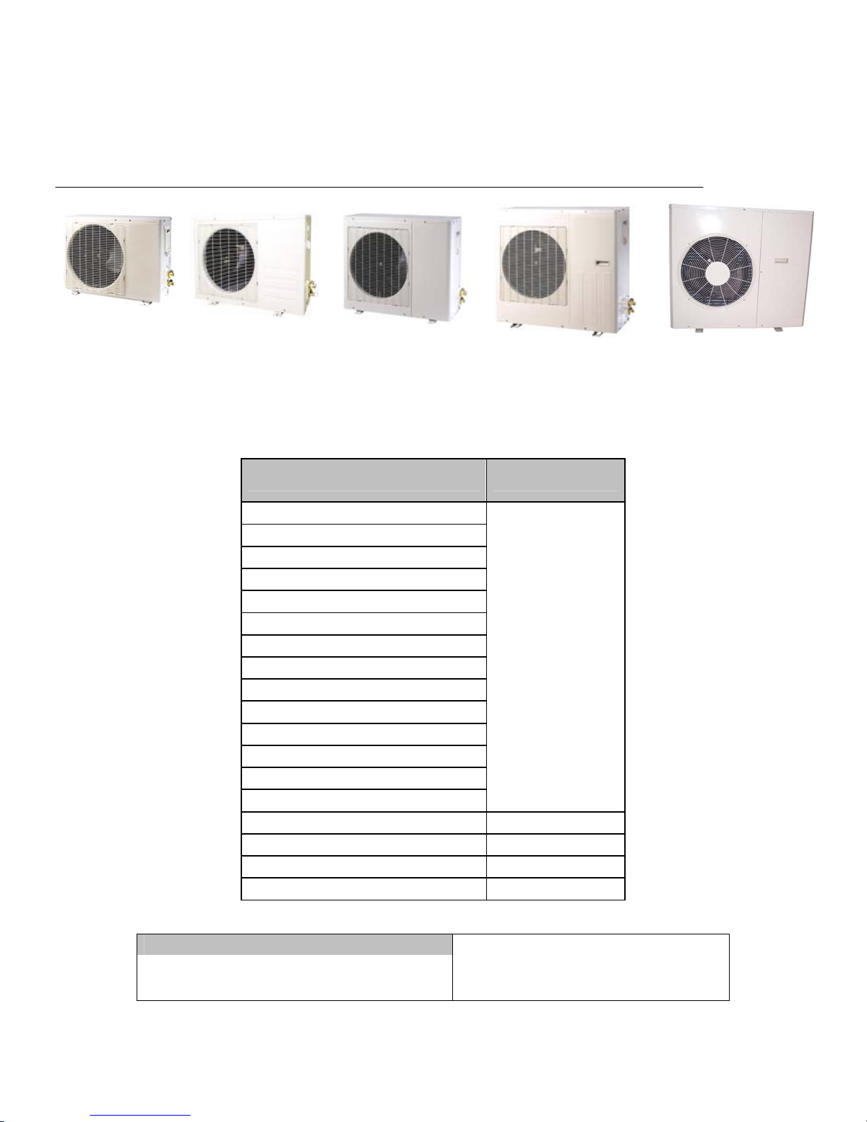
DC Inverter Multi-Split Air-Condition Unit
TAS-09EH/O TAS-12EH/O TAS-18EH/O TAS-24EH/O TAS-24MVH/O
TAS-18MVH/O
Indoor Unit Outdoor Unit
TAS-09MVH
TAS-12MVH
TAS-09EH TAS-09EH/O
TAS-12EH TAS-12EH/O
TAS-18EH TAS-18EH/O
TAS-24EH TAS-24EH/O
TAS-18MVH/O
TAS-24MVH/O
REFRIGERENT
R410A
HEAT PUMP
1 SERVICE MANUAL FOR AMERICA
Page 2

Table of Contents
1. INTRODUCTION .................................................................................................. 1-1
2. PRODUCT DATA SHEET ................................................... ................................. 2-1
3. RATING CONDITIONS ........................................................................................ 3-1
4. OUTLINE DIMENSIONS ...................................................................................... 4-1
5. PERFORMANCE DATA ...................................................................................... 5-1
6. PRESSURE CURVES .......................................................................................... 6-1
7. ELECTRICAL DATA .............................................................................................. 7-1
8. WIRING DIAGRAMS ............................................................................................ 8-1
9. REFRIGERATION DIAGRAMS ........................................................................... 9-1
10. TUBING CONNECTIONS ...................................................................................... 10-1
11. CONTROL SYSTEM ............................................................................................ 11-1
12. TROUBLESHOOTING ......................................................................................... 12-1
13. EXPLODED VIEWS AND SPARE PARTS LISTS ................................................ 13-1
14. APPENDIX A
2 SERVICE MANUAL FOR AMERICA
Page 3

1. INTRODUCTION
1.1 General
The new CMV and CS is a high efficiency DC inverter technology outdoor unit,
since it’s a lego concept unit, it can be matched to several inverter indoor units such as wall
mounted type with a capacity range of 9000 – 12000 BTU for each single indoor unit.
1.2 Main Features
DC Inverter
R410a
sine wave form and 120 degree rectangular wave form in compressor driver
sensor less inverter compressor driver
high speed calculation for accurate sine wave form vector control
smart PFC control
fuzzy logic con
High SEER
Lego Concept
Pre-Charged.
Cooling operation at outdoor temperature down to 50
Heating operation at outdoor temperature down to 5
Variable Speed outdoor fan.
Low noise level
EEV for each indoor unit
trol
0
0
F.
F
1.3 Tubing Connections
Flare type interconnecting tubing to be produced on site.
For further details please refer to APPENDIX A on this manual, and to the relevant indoor service
Manual,
1.4 Inbox Documentation
Each indoor unit is supplied with its own installation and operation manuals.
3 SERVICE MANUAL FOR AMERICA
Page 4
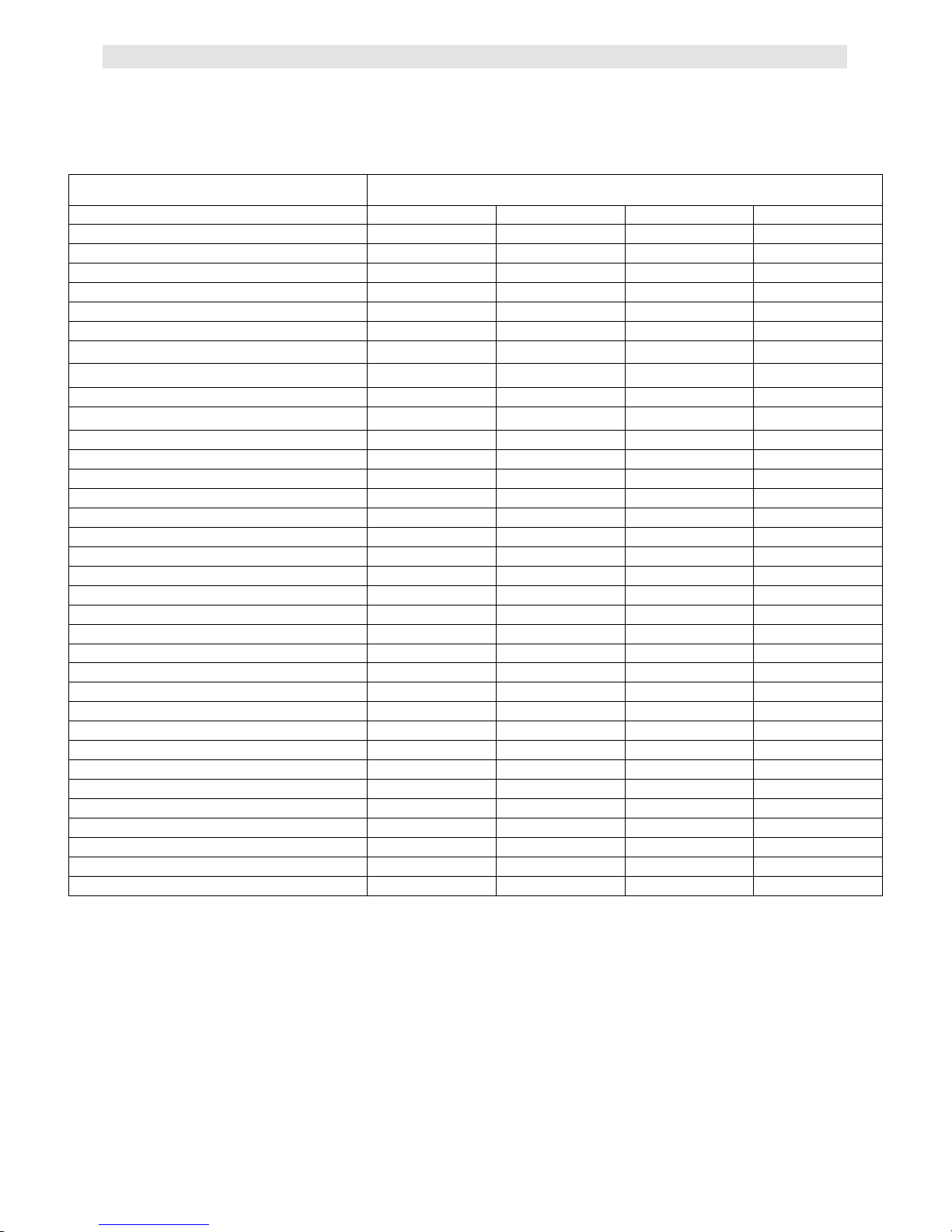
2. PRODUCT DATA SHEET
2.1 Outdoor unit data
2.1.1 DC Invertor 1:1.
Item
Capacity (BTU)
Cooling
Heating
SEER
HSPF
EER Cooling/COP Heating
Op Range Cool °F
Op Range Heat °F
Remote control setting temp.range °F
Dehumidification (Pts/hr)
Voltage
Current (A) Rated/Max Cooling
Heating
Power Consumption (KW)Rated/Max Cooling
Heating
Max Overload Protection
Indoor Air Circulation: L / M / H(CFM)
Indoor Noise level dB(A): L / M / H
Outdoor Fan Speed (RPM)
Outdoor Noise Level dB(A)
Indoor Fan Speeds
Connection Method
Max Pipe Length (Ft.)
Max Elevation (Ft.)
Pipe Size (In.)
Service Port Connection (In.)
Indoor Dimensions W x D x H(In.)
Indoor Package Dimensions W x D x H(In.)
Indoor Net Weight (lbs.)
Indoor Gross Weight(lbs. )
Outdoor Dimensions W x D x H(In.)
Outdoor Package Dimensions W x D x H(In.)
Outdoor Net Weight (lbs.)
Outdoor Gross Weight(lbs. )
Refrigerant
DC INVERTER 1:1
Inverter 9K Inverter 12K Inverter 18K Inverter 24K
9000
11000
18.00 18.00 17.17 15.69
8.6 8.7 8.7 8.5
4.0/3.7 4.0/3.6 3.60/3.60 2.87/3.18
5~131 5~131 5~131 5~131
minus 4 ~ 109 minus 4 ~ 109 minus 4 ~ 109 minus 4 ~ 109
61~90 61~90 61~90 61~90
1.58 2.11 2.989 4.4
115/60 115/60 230/60 230/60
5.5/9.32 7.53/10.8 5.929/10.1 11.09/12.22
7.1/9.8 10.4/13.0 6.732/9.31 10.24/12.23
0.61/1.06 0.862/1.236 1.345/2.3 2.504/2.765
0.8/1.11 1.19/1.496 1.532/2.124 2.314/2.768
20 20 20 25
212/270/315 341/382/430 441/530/618 518/588/677
42/38/35 42/38/35
100~900 100~900 100~900 100~900
~ 57 ~ 57 ~ 57 ~ 57
950/1150/1300 750/900/1000 950/1100/1230 1080/1180/1280
Flare Flare Flare Flare
82ft/25m 82ft/25m 82ft/25m 82ft/25m
32.8 Ft/10m 32.8 Ft/10m 32.8 Ft/10m 32.8 Ft/10m
1/4" / 3/8" 1/4" / 1/2" 3/8" / 5/8" 3/8" / 5/8"
1/2" 1/2" 1/2" 1/2"
33.4×13.4×9.8 38.4×14.3×11.0 45.8×15.2×12.0 52.0×15.6×12.0
33.9×13.8×10.4 39.0×14.8×11.8 46.3×15.6×12.6 52.6×16.1×12.6
22
26 37 51 55
35.6×12.7×22.6 38.6×15.7×26.0 38.2×15.6×29.9 40.2×17.1×34.1
36.2×13.2×23.0 39.2×16.3×26.8 39.0×16.1×30.3 40.6×17.3×37.8
73 106 123 143
77 117 132 154
R410A R410A R410A R410A
12000 18000 24000
15000 19000 24500
50/47/44 50/47/44
31 40 44
4 SERVICE MANUAL FOR AMERICA
Page 5
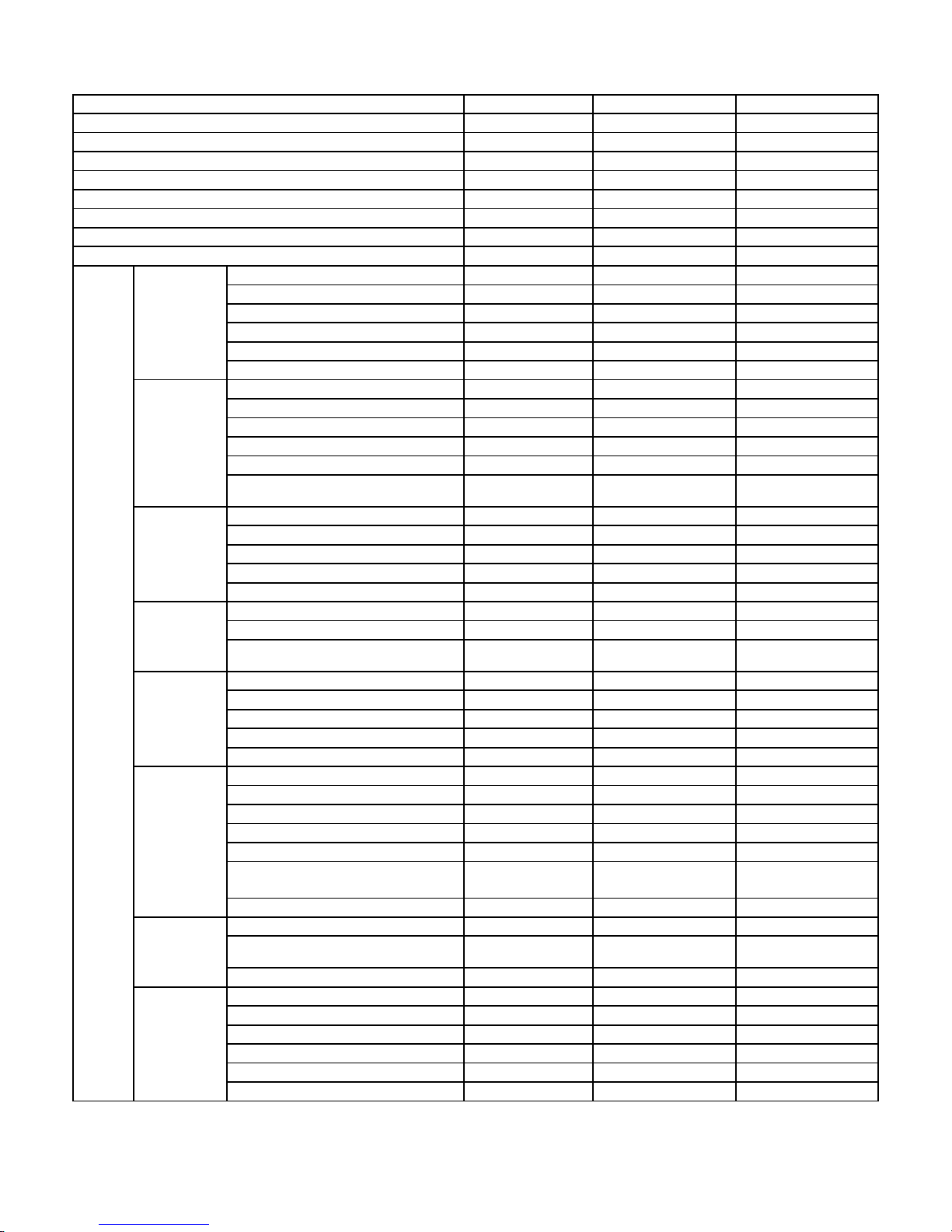
2.1.2 DC Inverter 1:2
TAS-18MVH/O TAS-24MVH/O
Function Heat Pump
Rated Voltage 208-230 VAC
Rated Frequency 60 Hz
Circuit Breaker Size 20A
Op Range Cool °F
Op Range Heat °F
Rated Current (RLA) (Heating/Cooling) 6 / 6.7 A
Refrigerant (lbs) R410A / 3.88
Rated Capacity (Btu) 18,000 24,000
Capacity Invert Range (W) 5000(1650-7100) 6400(1750-8300)
Cooling
Heating
Fan Motor
Outdoor
Fan
outdoor
Compressor
Condenser
Dimensions
Connection
Input / Actual Input (W) 1380/1450 1830/1882
Max. Power (W) 2420 2990
Max Current (A) 10.5 13
SEER 14.8 15.6*
Rated Capacity (Btu) 22,000
Capacity Invert Range (W) 5800(1790-7800) 7200(2000-8400)
Input / Actual Input (W) 1,550 / 1,580 2,000 / 2,060
Max. Power (W) 2579
Max Current (A) 11.3
Declared COP / Actual COP
(w/w.h.)
Model YDK-60A-6C
Input (W) 196
Capacitor (UFD) 4 / 450 VAC
Fan Motor FLA (A) 0.98 0.98
Fan Speed (RPM) 900/750/500
Fan Type Axial
Fan Blade Diameter (in) 18.1
Air Flow Volume of Outdoor Unit
(CFM)(M^3/h)
Model C-6RZ146H1A
TYPE DC
Brand Sanyo
Capacity (W) 6420
Input (W) 1635
Number of Row s 2-26 2-26
Tube Pitch x Row Pitch 1 x .866 in
Fin spacing 0.0708 in
Fin Type Louvered Fin
Tube Outside Dia. and Type 0.375" Rifled Tube 0.375" Rifled tube
Coil Length x Height x Width
Number of circuits
Unit Dimensions (W x H x D) (in) 36.5 x 14.25 x 27.6
Packing dimensions (W x H x D)
(in)
Net / Gross Weight (lb)
Design Length 16.4'
Max Line Set Height 16.4'
Max Line Set Length 49.21'
Charge over Design Length 0.20 oz / Ft. 0.20 oz / Ft.
Connection Pipes 1/4" / 3/8"
Design Pressure (PSI) 623.66
5~131 5~131
minus 4 ~ 109 minus 4 ~ 109
3.75 / 3.65 3.5 / 3.4
2800 3200
28.66 x 25.6 x .866
28.66 x 25.6 x .988
4 4
39 x 16.14 x 30.32 41.73 x 18.5 x 36.41
114.64 / 123.47 163.14 / 185.18
Heat Pump
208-230 VAC
60 Hz
30A
8 / 8.7 A
R410A / 6.61
25,000
3,200
13.9
YDK-60A-6C
196
4/ 450 VAC
900/750/500
Axial
18.5
C-7VRN153HOW
DC
Sanyo
7110
1770
1 x .866 in
0.0708 in
Louvered Fin
30.23 x 31.96 x .866
31.57 x 31.96 x .866
37.8x13.54x33.31
16.4'
16.4'
49.21'
1/4" x 1/2"
623.66
5 SERVICE MANUAL FOR AMERICA
Page 6
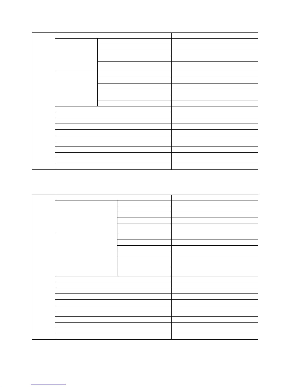
2.2 Indoor Units Data
2.2.1 TAS-09MVH Specifica tions
Indoor
Model
Input (W)
FAN MOTOR
Evaporator
Air Flow (Hi/Med/Low) (CFM) 353 / 306 / 194
Noise Level (dB(A) ≤42
Fan Type Cross Flow
Fan Diameter (in) 3.661
Fan Length (in) 24.921
Design Pressure (PSI) 551.14
Unit Dimensions (W x H x D) (in) 31.1 x 10.63 x 8.27
Packing Dimensions W x H x D) (in) 33.86 x 13.78 x 10.43
Net / Gross Wt (lbs) 26.45 / 30.86
Dehumidifying Volume (pt/hr) 1.8
Auto-restart YES
Capacitor (UFD)
Fan Motor FLA (A)
Speed (Hi/Med/Low) (RPM) 1150 / 950 / 750
Number of rows
Tube pitch row / pitch (in) .69 / .50
Fin spacing (in)
Fin Type
Tube outside dia.(in) / Type 0.2756 Rifled Tube
Coil Length x height x width (in) 25.39 x 11.06 x 1
TAS-09MVH
YDK-16-4C
54
1.2/450VAC
0.25
22
0.0614
Louvered Fin
2.2.2
Indoor
TAS-12MVH Specifica tions
TAS-12MVH
Model
Input (W) 54
FAN MOTOR
Evaporator
Air Flow (Hi/Med/Low) (CFM) 459 / 406 / 218
Noise Level (dB(A) ≤45
Fan Type Cross Flow
Fan Diameter (in) 3.818
Fan Length (in) 30.393
Design Pressure (PSI) 551.14
Unit Dimensions (W x H x D) (in) 36.61 x 10.83 x 8.27
Packing Dimensions W x H x D) (in)
Net / Gross Wt (lbs) 30.86 / 37.48
Dehumidifying Volume (pt/hr)
Auto-restart YES
Capacitor (UFD) 1.2/450VAC
Fan Motor FLA (A) 0.25
Speed (Hi/Med/Low)
(RPM)
Number of rows
Tube pitch row / pitch (in) .69 / .50
Fin spacing (in)
Fin Type
Tube outside dia.(in) /
Type
Coil Length x height x
width (in)
1200 / 950 / 850 (Cooling) 1200 / 950 / 750
YDK-16-4C
(Heating)
22
0.059
Louvered Fin
0.2756 Rifled Tube
30.98 x 11.06 x 1
39.96 x 13.97 x 12.79
3.03
6 SERVICE MANUAL FOR AMERICA
Page 7
3. RATING CONDITIONS
Standard conditions in accordance with ANSI/AHAM RAC-1-2003, and UL 484.
Cooling:
Indoor: 80
Outdoor: 95
o
FDB 67oF WB
o
F DB 75oF WB
Heating:
Indoor: 70
Outdoor: 47
o
F DB 60 oF WB
o
F DB 43 oF WB
3.1 Operating Limits
Cooling
Upper limit (DB)
Lower limit (DB) 5oF
Heating
Upper limit (DB) 75
Lower limit (DB) 5oF
Voltage
2PH 198–264V/115V
3PH N/A
Outdoor
o
F
110
o
F
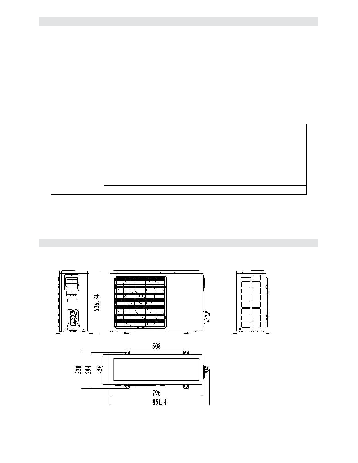
4. OUTLINE DIMENSIONS
4.1 outdoor Unit: TAS-09EH/O
7 SERVICE MANUAL FOR AMERICA
Page 8
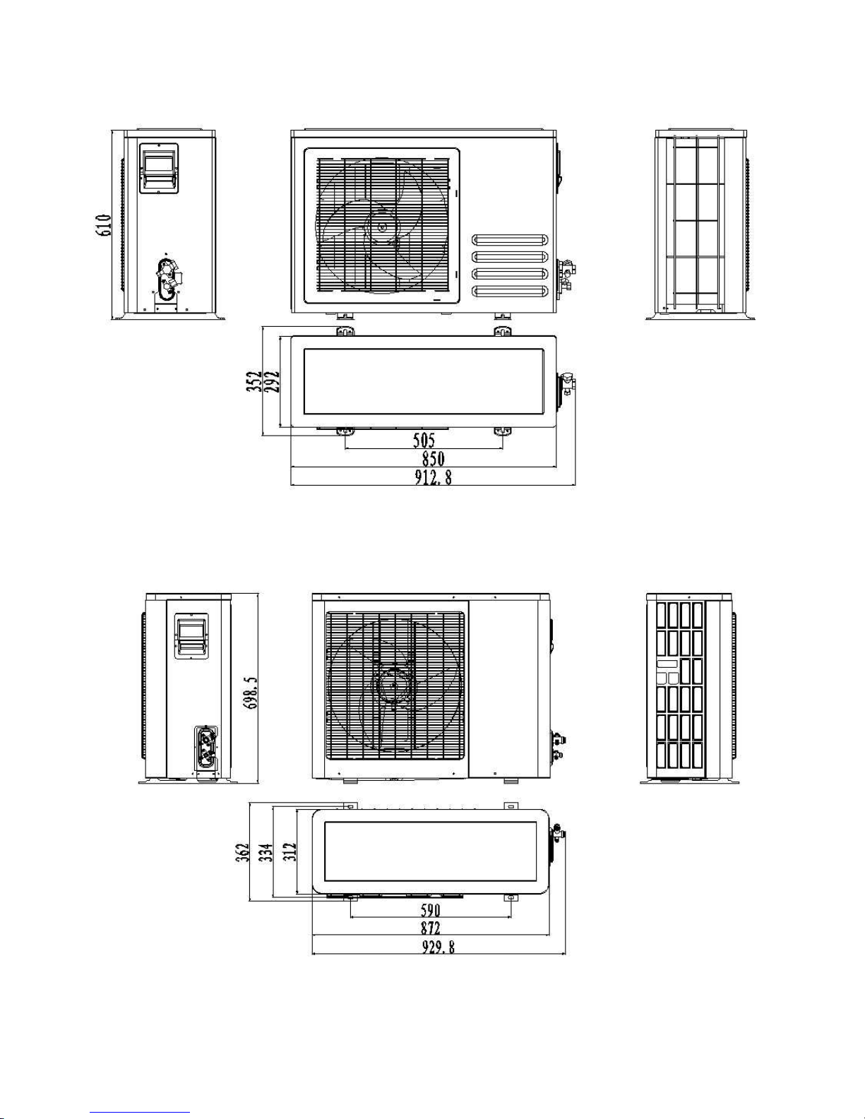
4.2 outdoor Unit: TAS-12EH/O
4.3 outdoor Unit: TAS-18EH/O
4.4 outdoor Unit: TAS-24EH/O
8 SERVICE MANUAL FOR AMERICA
Page 9
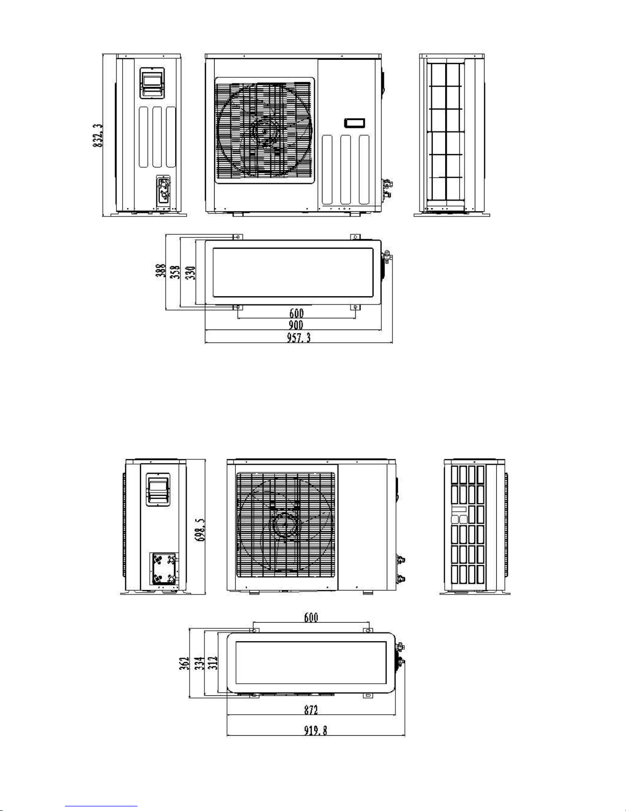
4.5 outdoor Unit: TAS-18MVH/O
9 SERVICE MANUAL FOR AMERICA
Page 10
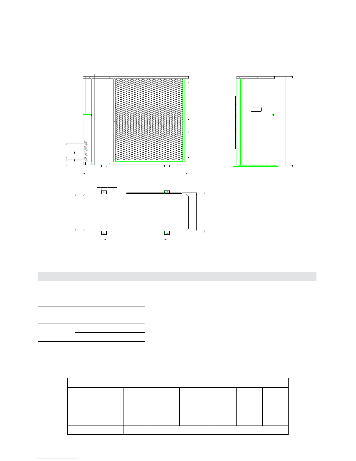
4.7 outdoor Unit:
50×3(=150)
50
72
TAS-24MVH/O
956
50
825
845
351
342
560
378
5. PERFORMANCE DATA
5.1 Indoor Units Data
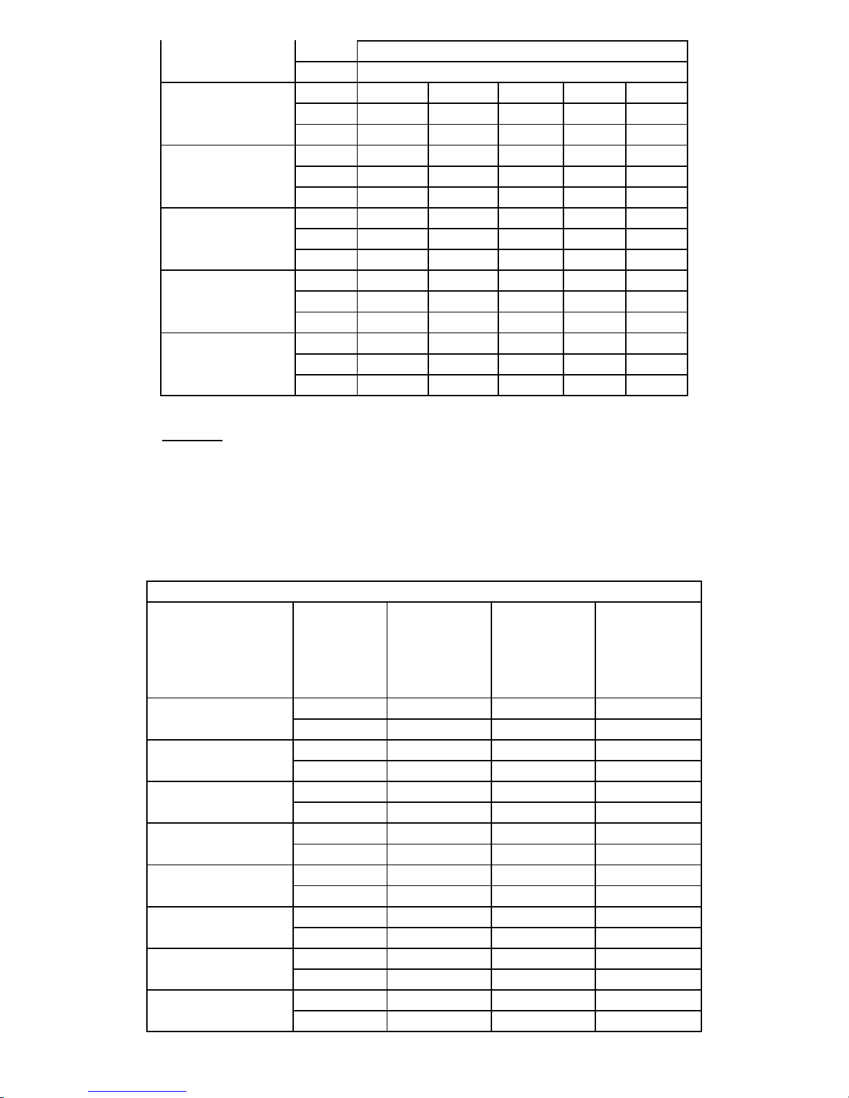
5.1.1 Indoor Units Capacity For 9000BTU
Capacity Model
9000BTU
5.1.1.1 Cooling Capacity (BTU)---Run Model (Unit A,B,C or D),230/115V,Indoor fan at
TAS-09MVH
TAS-09EH
high speed
INDOOR ENTERING AIR DB/WB TEMPERATURE [0F]
OUTDOOR
ENTERING AIR DB
TEMPERATURE[
14~68
0
F]
DATA 72/59 75/63 81/66 84/70 90/73
TC 80 - 110 % of nominal
10 SERVICE MANUAL FOR AMERICA
Page 11
(protection range)
SC 80 - 105 % of nominal
PI 25 - 50 % of nominal
TC 8712 9252 9828 10404 10980
77
SC 6273 6382 6528 6638 6784
PI 0.58 0.59 0.6 0.61 0.62
TC 8280 8856 9432 9972 10548
86
SC 6091 6236 6346 6492 6601
PI 0.65 0.66 0.67 0.68 0.69
TC 7848 8424 9000 9576 10152
95
SC 5945 6054 6200 6346 6455
PI 0.71 0.72 0.74 0.75 0.76
TC 7452 8028 8568 9144 9720
104
SC 5799 5908 6054 6164 6309
PI 0.78 0.79 0.8 0.81 0.82
TC 6948 7524 8064 8640 9216
115
SC 5580 5726 5835 5981 6091
PI 0.86 0.87 0.88 0.89 0.91
LEGEND
TC – Total Cooling Capacity, BTU SC – Sensible Capacity, BTU PI – Power Input, kW
WB – Wet Bulb Temp., (
0
F
) DB – Dry Bulb Temp., (
0
F
) ID – Indoor OD – Outdoor
5.1.1.2 Heating Capacity (BTU)---Run Model (Unit A,B,C or D),230/115V,Indoor fan at
high speed
ID COIL ENTERING AIR DB TEMPERATURE [0F]
OD COILENTERING
AIR DB/WB TEM
PERATU RE[
0
F]
5/3
14/10
20/18
30/28
36/34
45/43
50/48
59/54
DATA 59 68 77
TC 6912 6372 5940
PI 0.49 0.54 0.59
TC 7668 7128 6696
PI 0.59 0.64 0.70
TC 8208 7776 7236
PI 0.67 0.72 0.77
TC 8532 8100 7560
PI 0.71 0.75 0.80
TC 8748 8208 7776
PI 0.89 0.95 1.01
TC 11232 10800 10368
PI 0.77 0.82 0.87
TC 11880 11448 10908
PI 0.82 0.87 0.92
TC 12528 12096 11556
PI 0.86 0.90 0.96
11 SERVICE MANUAL FOR AMERICA
Page 12
59~75
(Protection Range)
TC 85 - 105 % of nominal
PI 80 - 120 % of nominal
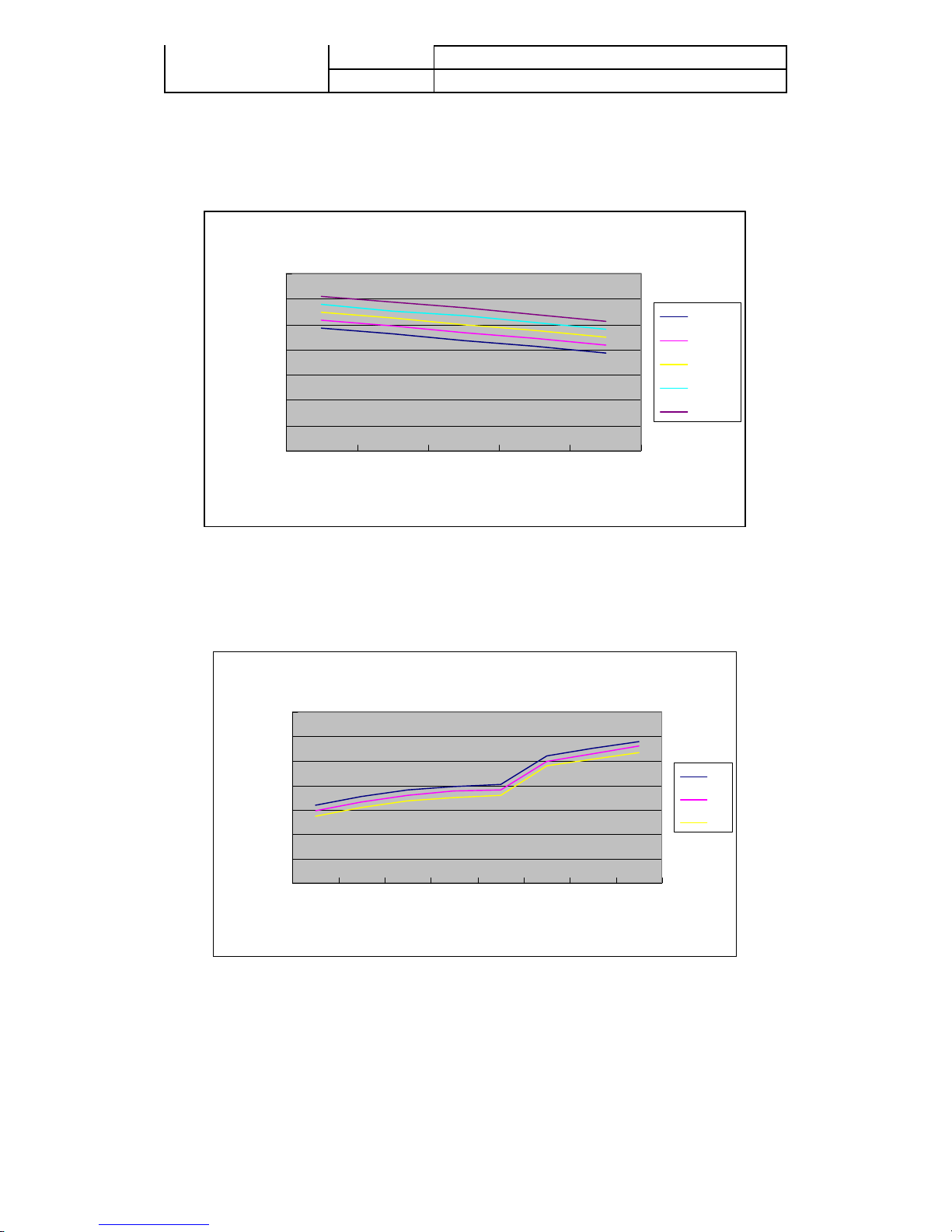
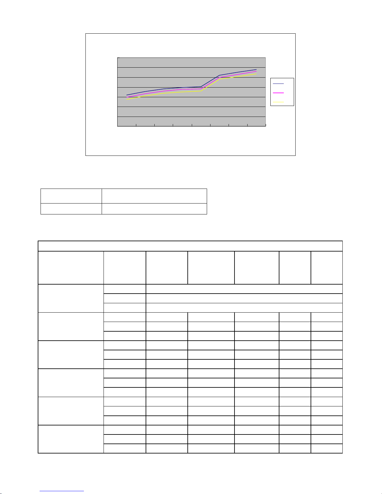
5.1.1.3 Capacity Correction Factors
Cooling Capacity Ratio Vs. Outdoor Temperature
Cooling Capacity Correction Factor
1.4
1.2
1
0.8
0.6
0.4
Capacity Ratio
0.2
0
77 86 95 104 115
Outdoor Temp.(deg F)
90/73
84/70
81/66
75/63
72/59
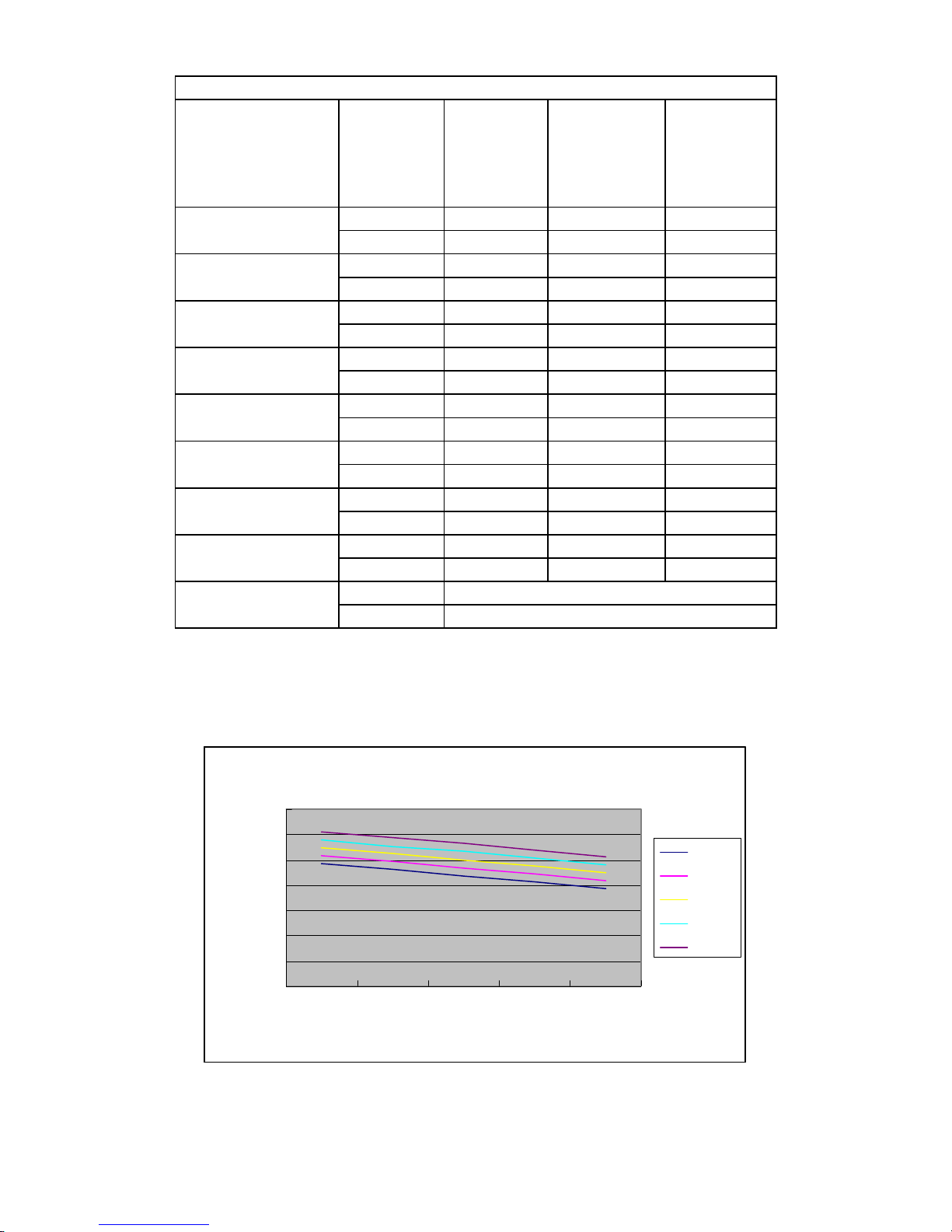
Heating Capacity Ratio Vs. Outdoor Temperature
Heating Capacity Correction Factor
1.4
1.2
1
0.8
0.6
0.4
Capacity Ratio
0.2
0
5 14203036455059
Outdoor Temp.(deg F)
59
68
77
12 SERVICE MANUAL FOR AMERICA
Page 13
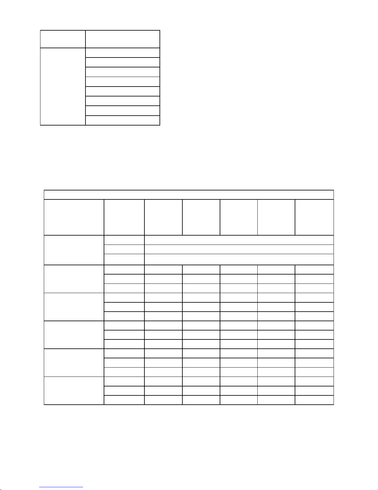
5.2.1 Indoor Units Capacity For 12000BTU
Capacity Model
12000BTU
TAS-12MVH
TAS-12EH
5.2.1.1 Cooling Capacity (BTU)---Run Model (Unit A,B,C or D),230/115V,Indoor fan at
high speed
OUTDOOR
ENTERING AIR DB
TEMPERATURE[
14~68
(protection range)
77
86
95
104
115
INDOOR ENTERING AIR DB/WB TEMPERATURE [0F]
0
F]
DATA 72/59 75/63 81/66 84/70 90/73
TC 80 - 110 % of nominal
SC 80 - 105 % of nominal
PI 25 - 50 % of nominal
TC 11616 12336 13104 13872 14640
SC 10421 10603 10845 11027 11269
PI 0.72 0.73 0.75 0.76 0.77
TC 11040 11808 12576 13296 14064
SC 10118 10361 10542 10785 10966
PI 0.81 0.82 0.83 0.85 0.86
TC 10464 11232 12000 12768 13536
SC 9876 10058 10300 10542 10724
PI 0.88 0.90 0.92 0.93 0.94
TC 9936 10704 11424 12192 12960
SC 9634 9815 10058 10239 10482
PI 0.97 0.98 0.99 1.01 1.02
TC 9264 10032 10752 11520 12288
SC 9270 9512 9694 9936 10118
PI 1.07 1.08 1.09 1.11 1.13
13 SERVICE MANUAL FOR AMERICA
Page 14
5.2.1.2 Heating Capacity (KW)---Run Model (Unit A,B,C or D),230V,Indoor fan at high
speed
ID COIL ENTERING AIR DB TEMPERATURE [0F]
OD COILENTERING
AIR DB/WB TEM
PERATU RE[
0
F]
DATA 59 68 77
5/3
14/10
20/18
30/28
36/34
45/43
50/48
59/54
59~75
(Protection Range)
TC 8960 8260 7700
PI 0.66 0.73 0.80
TC 9940 9240 8680
PI 0.80 0.87 0.95
TC 10640 10080 9380
PI 0.91 0.97 1.04
TC 11060 10500 9800
PI 0.96 1.02 1.08
TC 11340 10640 10080
PI 0.99 1.06 1.12
TC 14560 14000 13440
PI 1.04 1.11 1.18
TC 15400 14840 14140
PI 1.11 1.18 1.25
TC 16240 15680 14980
PI 1.16 1.22 1.30
TC 85 - 105 % of nominal
PI 80 - 120 % of nominal
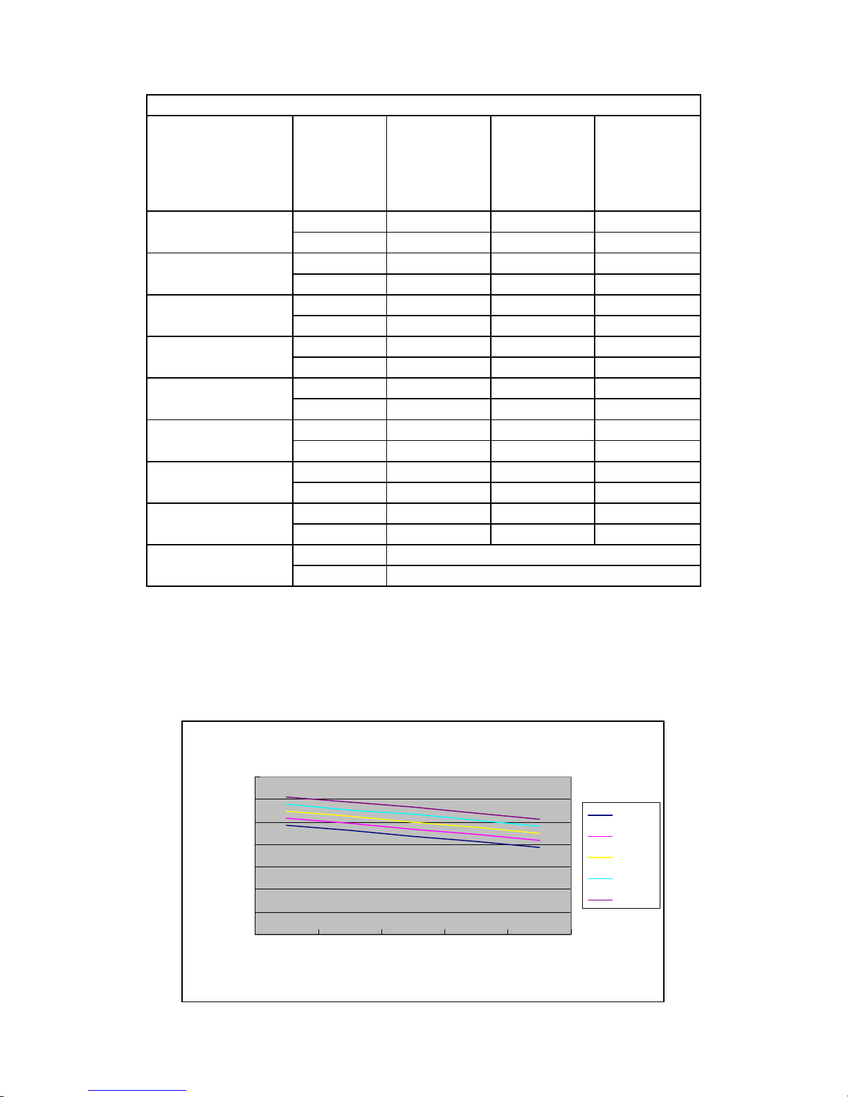
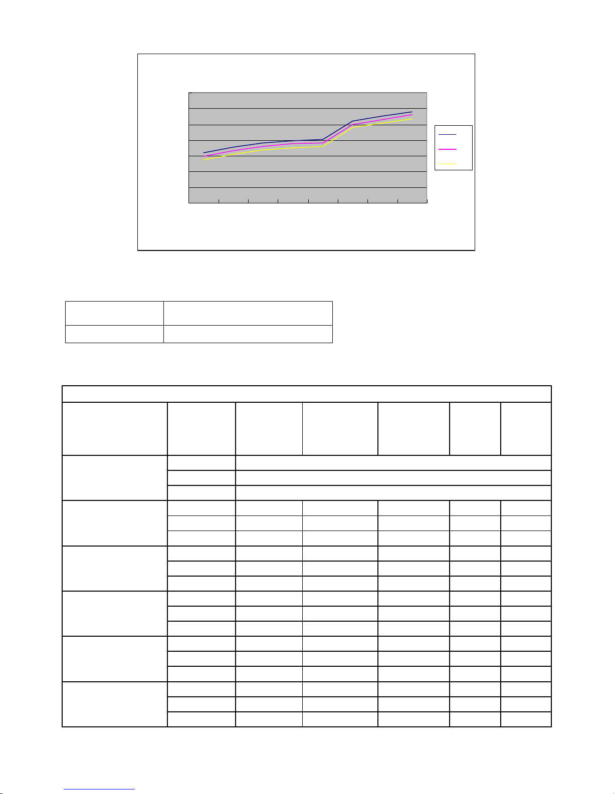
5.2.1.3 Capacity Co rrection Factors
Cooling Capacity Ratio Vs. Outdoor Temperature
Cooling Capacity Correction Factor
1.4
1.2
1
0.8
0.6
0.4
Capacity Ratio
0.2
0
77 86 95 104 115
Outdoor Temp.(deg F)
14 SERVICE MANUAL FOR AMERICA
90/73
84/70
81/66
75/63
72/59
Page 15
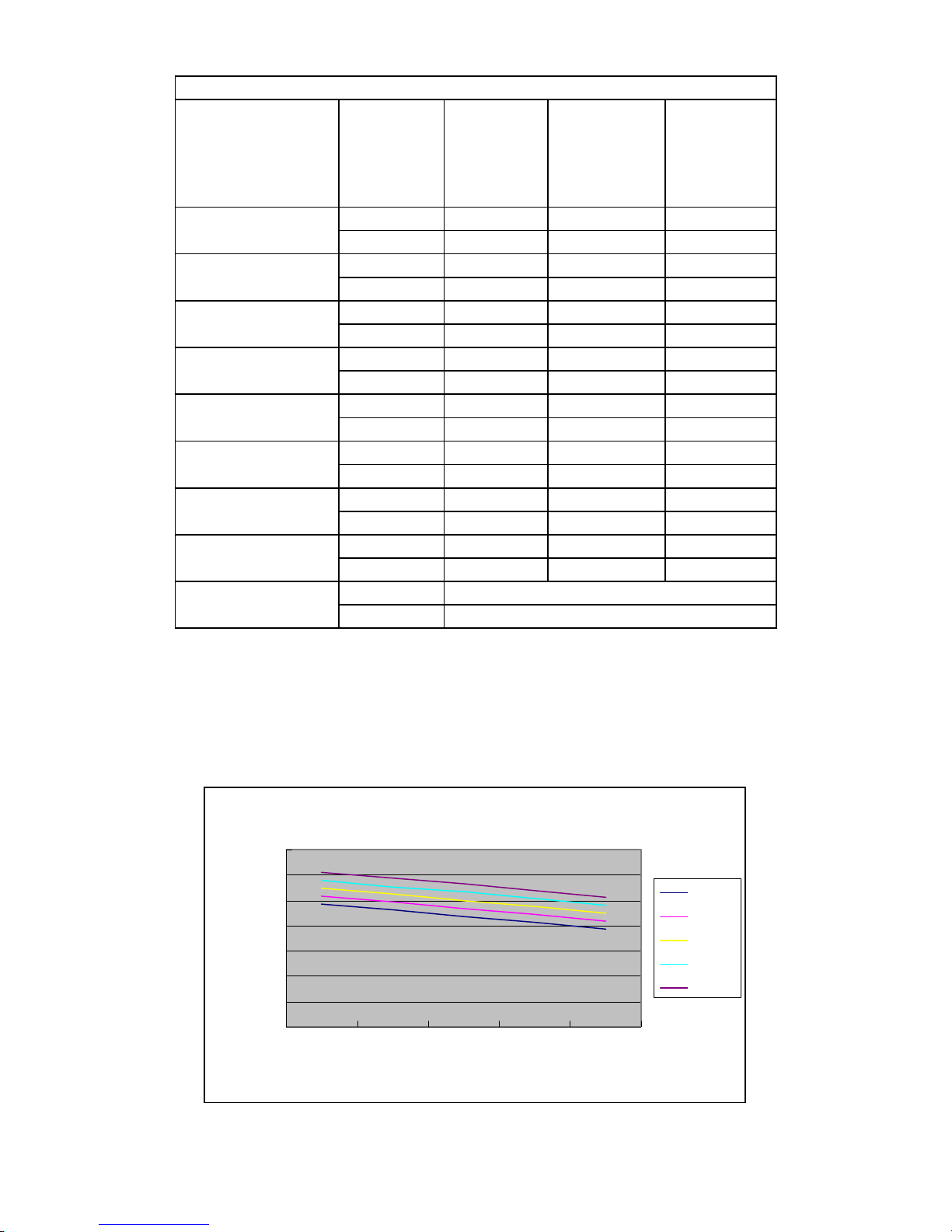
Heating Capacity Ratio Vs. Outdoor Temperature
Heating Capacity Correction Factor
1.4
1.2
1
0.8
0.6
0.4
Capacity Ratio
0.2
0
5 14203036455059
Outdoor Temp.(deg F)
5.2.3 Indoor Units Capacity For 18000BTU
59
68
77
Capacity Model
18000BTU TAS-18EH
5.2.3.1 Cooling Capacity (BTU)---Run Model ,230V,Indoor fan at high speed
INDOOR ENTERING AIR DB/WB TEMPERATURE [0F]
OUTDOOR
ENTERING AIR DB
TEMPERATURE[0F]
14~68
(protection range)
77
86
95
104
115
DATA 72/59 75/63 81/66 84/70 90/73
TC 80 - 110 % of nominal
SC 80 - 105 % of nominal
PI 25 - 50 % of nominal
TC 17424 18504 19656 20808 21960
SC 15480 15750 16110 16380 16740
PI 1.19 1.21 1.23 1.25 1.27
TC 16560 17712 18864 19944 21096
SC 15030 15390 15660 16020 16290
PI 1.34 1.36 1.38 1.40 1.42
TC 15696 16848 18000 19152 20304
SC 14670 14940 15300 15660 15930
PI 1.46 1.48 1.52 1.54 1.56
TC 14904 16056 17136 18288 19440
SC 14310 14580 14940 15210 15570
PI 1.60 1.62 1.64 1.66 1.68
TC 13896 15048 16128 17280 18432
SC 13770 14130 14400 14760 15030
PI 1.77 1.79 1.81 1.83 1.87
15 SERVICE MANUAL FOR AMERICA
Page 16
5.2.3.2 Heating Capacity (BTU)---Run Model,230V,Indoor fan at high speed
ID COIL ENTERING AIR DB TEMPERATURE [0F]
OD COILENTERING
AIR DB/WB TEM
PERATU RE[
0
F]
DATA 59 68 77
5/3
14/10
20/18
30/28
36/34
45/43
50/48
59/54
59~75
(Protection Range)
TC 12160 11210 10450
PI 0.96 1.05 1.15
TC 13490 12540 11780
PI 1.15 1.25 1.37
TC 14440 13680 12730
PI 1.31 1.40 1.50
TC 15010 14250 13300
PI 1.39 1.46 1.56
TC 15390 14440 13680
PI 1.42 1.52 1.62
TC 19760 19000 18240
PI 1.50 1.60 1.70
TC 20900 20140 19190
PI 1.60 1.70 1.80
TC 22040 21280 20330
PI 1.68 1.76 1.87
TC 85 - 105 % of nominal
PI 80 - 120 % of nominal
5.2.3.3 Capacity Co rrection Factors
Cooling Capacity Ratio Vs. Outdoor Temperature
Cooling Capacity Correction Factor
1.4
1.2
1
0.8
0.6
0.4
Capacity Ratio
0.2
0
77 86 95 104 115
Outdoor Temp.(deg F)
90/73
84/70
81/66
75/63
72/59
16 SERVICE MANUAL FOR AMERICA
Page 17
Heating Capacity Ratio Vs. Outdoor Temperature
Heating Capacity Correction Factor
1.4
1.2
1
0.8
0.6
0.4
Capacity Ratio
0.2
0
5 14203036455059
Outdoor Temp.(deg F)
5.2.4 Indoor Units Capacity For 24000BTU
59
68
77
Capacity Model
24000BTU TAS-24EH
5.2.4.1 Cooling Capacity (BTU)---Run Model,230V,Indoor fan at high speed
INDOOR ENTERING AIR DB/WB TEMPERATURE [0F]
OUTDOOR
ENTERING AIR DB
TEMPERATURE[0F]
14~68
(protection range)
77
86
95
104
115
DATA 72/59 75/63 81/66 84/70 90/73
TC 80 - 110 % of nominal
SC 80 - 105 % of nominal
PI 25 - 50 % of nominal
TC 23232 24672 26208 27744 29280
SC 20640 21000 21480 21840 22320
PI 1.72 1.75 1.78 1.81 1.84
TC 22080 23616 25152 26592 28128
SC 20040 20520 20880 21360 21720
PI 1.93 1.96 1.99 2.02 2.05
TC 20928 22464 24000 25536 27072
SC 19560 19920 20400 20880 21240
PI 2.11 2.14 2.20 2.23 2.26
TC 19872 21408 22848 24384 25920
SC 19080 19440 19920 20280 20760
PI 2.32 2.35 2.38 2.41 2.44
TC 18528 20064 21504 23040 24576
SC 18360 18840 19200 19680 20040
PI 2.56 2.59 2.62 2.65 2.71
17 SERVICE MANUAL FOR AMERICA
Page 18
5.2.4.2 Heating Capacity (BTU)---Run Model,230V,Indoor fan at high speed
ID COIL ENTERING AIR DB TEMPERATURE [0F]
OD COILENTERING
AIR DB/WB TEM
PERATU RE[
0
F]
DATA 59 68 77
5/3
14/10
20/18
30/28
36/34
45/43
50/48
59/54
59~75
(Protection Range)
TC 15680 14455 13475
PI 1.35 1.49 1.63
TC 17395 16170 15190
PI 1.63 1.76 1.93
TC 18620 17640 16415
PI 1.85 1.98 2.12
TC 19355 18375 17150
PI 1.96 2.07 2.20
TC 19845 18620 17640
PI 2.01 2.15 2.29
TC 25480 24500 23520
PI 2.12 2.26 2.40
TC 26950 25970 24745
PI 2.26 2.40 2.54
TC 28420 27440 26215
PI 2.37 2.48 2.65
TC 85 - 105 % of nominal
PI 80 - 120 % of nominal
5.2.4.3 Capacity Co rrection Factors
Cooling Capacity Ratio Vs. Outdoor Temperature
Cooling Capacity Correction Factor
1.4
1.2
1
0.8
0.6
0.4
Capacity Ratio
0.2
0
77 86 95 104 115
Outdoor Temp.(deg F)
90/73
84/70
81/66
75/63
72/59
18 SERVICE MANUAL FOR AMERICA
Page 19
Heating Capacity Ratio Vs. Outdoor Temperature
Heating Capacity Correction Factor
1.4
1.2
1
0.8
0.6
0.4
Capacity Ratio
0.2
0
5 14203036455059
Outdoor Temp.(deg F)
59
68
77
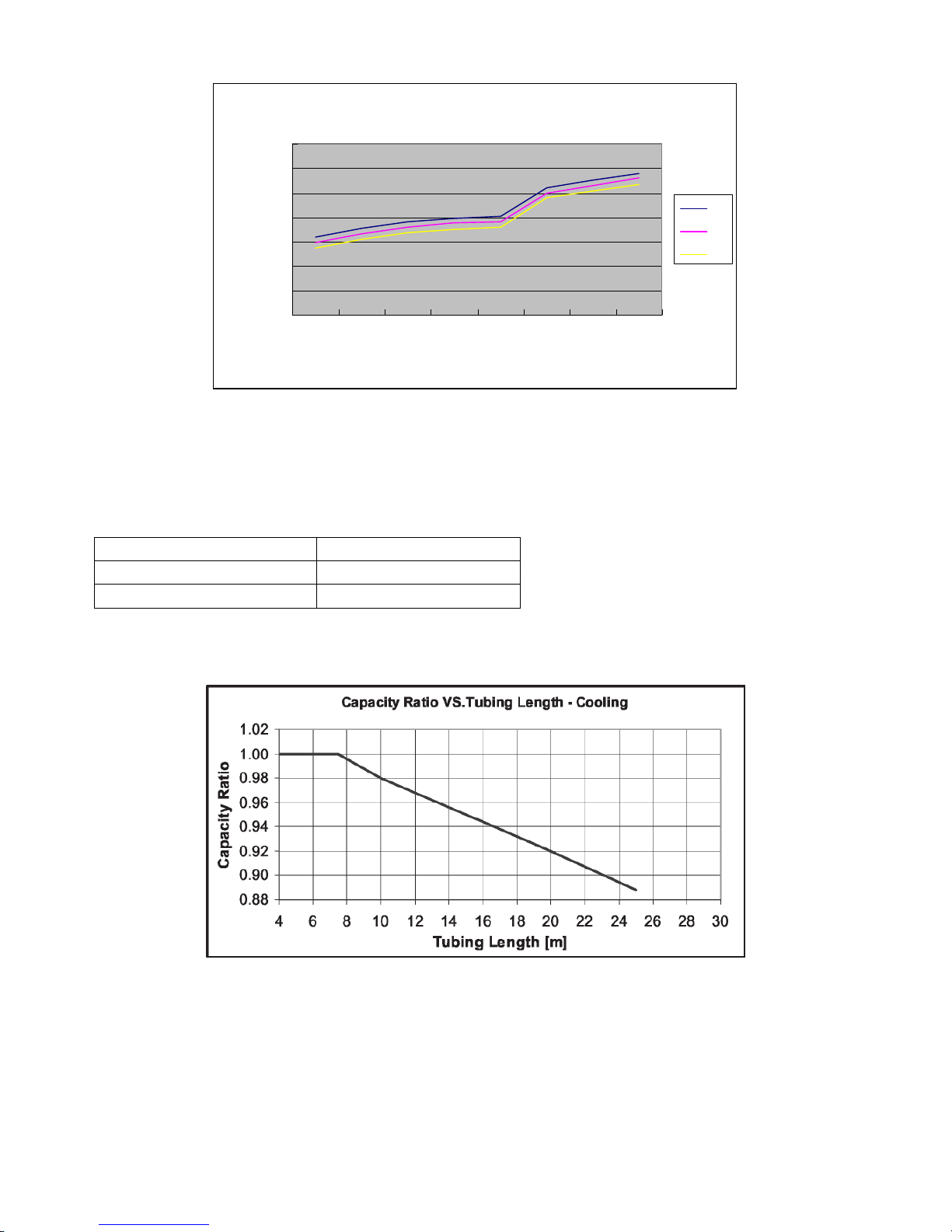
5.3 Capacity Correction Factor Due to Tubing Length (One Way)
5.3.1 Indoor units Model
TAS-09MVH TAS-12MVH
TAS-09EH TAS-12EH
TAS-18EH TAS-24EH
5.3.1.1 Cooling
5.3.1.2 Heating
19 SERVICE MANUAL FOR AMERICA
Page 20

6. Pressure Curve
6.1 Model
TAS-09EH/O TAS-18MVH/O
TAS-12EH/O TAS-24MVH/O
TAS-18EH/O
TAS-24EH/O
6.1.1 Suction Pressure Curve
6.1.2 Discharge Pressure Curve
20 SERVICE MANUAL FOR AMERICA
Page 21

7. ELECTRICAL DATA
Model
TAS-09EH/O
Power Supply 1 PH, 115 VAC,60Hz
Connected to Outdoor
Maximum Current 9.3A
Inrush Current 40A
Starting Current 1A
Circuit breaker 30A
Power supply wiring - No. x cross section 1 X 3 X 2.5 mm2
Interconnecting cable - No. x cross section
Model
2 X 4 X 1 mm
TAS-12EH/O
2
Power Supply 1 PH, 115 VAC,60Hz
Connected to Outdoor
Maximum Current 10.8A
Inrush Current 40A
Starting Current 1A
Circuit breaker 30A
Power supply wiring - No. x cross section 1 X 3 X 2.5 mm2
Interconnecting cable - No. x cross section
Model
2 X 4 X 1 mm
TAS-18EH/O
2
Power Supply 1 PH, 230 VAC,60Hz
Connected to Outdoor
Maximum Current 10.1A
Inrush Current 40A
Starting Current 1A
Circuit breaker 30A
21 SERVICE MANUAL FOR AMERICA
Page 22

Power supply wiring - No. x cross section 1 X 3 X 2.5 mm2
Interconnecting cable - No. x cross section
Model
2 X 4 X 1 mm
TAS-24EH/O
2
Power Supply 1 PH, 230 VAC,60Hz
Connected to Outdoor
Maximum Current 12.2A
Inrush Current 35A
Starting Current 1A
Circuit breaker 30A
Power supply wiring - No. x cross section 1 X 3 X 2.5 mm2
Interconnecting cable - No. x cross section
Model
2 X 4 X 1 mm
TAS-18MVH/O
2
Power Supply 1 PH, 230 VAC,60Hz
Connected to Outdoor
Maximum Current 10.5A
Inrush Current 40A
Starting Current 1A
Circuit breaker 20A
Power supply wiring - No. x cross section 1 X 3 X 2.5 mm2
Interconnecting cable - No. x cross section
Model
2 X 4 X 1 mm
TAS-24MVH/O
2
Power Supply 1 PH, 230 VAC,60Hz
Connected to Outdoor
Maximum Current 13A
Inrush Current 35A
Starting Current 1A
Circuit breaker 30A
Power supply wiring - No. x cross section 1 X 3 X 2.5 mm2
Interconnecting cable - No. x cross section
2 X 4 X 1 mm
2
Note:
Inrush current is the current when power is up. (charging the DC capacitors at outdoor unit
controller).
Starting current is the current when starting the compressor
Power wiring cord should comply with local lows and electrical
regulations requirements.
NOTE
22 SERVICE MANUAL FOR AMERICA
Page 23

8. WIRING DIAGRAMS
8.1 TAS-09EH/O Wiring Diagram
8.2 TAS-12EH/O Wiring Diagram
23 SERVICE MANUAL FOR AMERICA
Page 24

8.3 TAS-18EH/O Wiring Diagram
8.4 TAS-24EH/O Wiring Diagram
8.5 TAS-18MVH/O Wiring Diagram
24 SERVICE MANUAL FOR AMERICA
Page 25

8.6 TAS-24MVH/O Wiring Diagram
8.4 TAS-18MVH/O TAS-24MVH/O
Indoor-Outdoor Wiring Diagram
25 SERVICE MANUAL FOR AMERICA
Page 26

8.5 TAS-09EH/O TAS-12EH/O TAS-18EH/O TAS-24EH/O
Indoor-Outdoor Wiring Diagram
9. REFRIGERATION DIAGRAMS
26 SERVICE MANUAL FOR AMERICA
Page 27

9.1 TAS-09EH/O Refrigeration Diagram
9.2 TAS-12EH/O Refrigeration Diagram
9.3 TAS-18EH/O TAS-24EH/O Refrigeration Diagram
27 SERVICE MANUAL FOR AMERICA
Page 28

9.4 TAS-18MVH/O Refrigeration Diagram
9.5 TAS-24MVH/O Refrigeration Diagram
28 SERVICE MANUAL FOR AMERICA
Page 29

10. TUBING CONNECTIONS
29 SERVICE MANUAL FOR AMERICA
Page 30

TUBE (Inch)
TORQUE (Nm)
Flare Nuts
Valve Cap
Service Port Cap
¼” ~” ½” ~” ¾”
11-13 40-45 60-65 70-75 80-85
13-20 13-20 18-25 18-25 40-50
11-13 11-13 11-13 11-13 11-13
1. Valve Protection Cap-end
2. Refrigerant Valve Port (use Allen wrench to open/close)
3. Valve Protection Cap
4. Refrigerant Valve
5. Service Port Cap
6. Flare Nut
7. Unit Back Side
8. Copper Tube
When the outdoor unit is installed above the indoor unit an oil trap is required every 5m along the suction line at the
lowest point of the riser. Incase the indoor unit is installed above the outdoor, no trap is required
11. CONTROL SYSTEM
30 SERVICE MANUAL FOR AMERICA
Page 31

Function of Inverter indoor unit
一、summary
1. This control is use for DC Multi-Spilt air conditioners.
2. Power of indoor unit supply is 220-240V/50Hz, voltage range is 170V~270V.
3. Control precision of indoor temperature is ±1.8
4. Indoor fan motor is PG motor.
5. Control accord with :
GB5956-91《safe requirement of air conditioner》
GB7725-2004《air conditioner》;GB3797-87《control equipment of electrical equipment》
Vibrancy test:frequency 50Hz,acceleration 2.5g
PCB ought to accord with GB4588.1 and GB4588.2
Electromagnetism compatibility ought to accord with relate standard of nation.
二.Base parameter
1. Use condition:ambient temperature 5 OF~185 OF, relative humidity =30-95%.
2. Receive distance of remote:<10m
3. Angle of remote:<120 degree
O
4. Control precision of temperature: ±1.8
F
5. Speed precision of indoor fan motor: ±10RPM
6. Time precision: <0.1%
三.Major function of control
1. Remote
Turn on/off
Mode select
auto
cooling
dehumidify
heating
ventilation
Indoor fan speed select
manual mode: high, middle, low speed
auto mode: accord difference of indoor room temp. and set temp. automatic select.
Temperature setting
Cooling: 60
Heating : 60
Dehumidify: default is 77
Auto: default is 77
Ventilation: 60
Sleeping
It can set or cancel 24HR sleep .
Timer on or timer off
Timer can set 24HR on or off.
Air flower control.
Turbo running
Hold key
2. Main PCB board
O
F――90 OF, default is 77 OF
O
F――90 OF, default is 77 OF
O
O
F――90 OF, default is 77 OF
O
F and it can’t adjust.
F and it can’t adjust.
O
F.
31 SERVICE MANUAL FOR AMERICA
Page 32

five running modes
Auto, cooling, heating, dehumidify, ventilation.
Timer function
Indoor temperature detect.
Indoor coil temperature detect.
Indoor fan speed control
cooling: turbo/high speed/middle speed/low speed/ lower speed
heating: turbo/high speed/middle speed/low speed/ lower speed
Indicate lamp
green—running indicate
yellow—timer indicate
red—turbo running
green—economic running
Indoor temperature control
Coil pipe of indoor unit overheat protection
Coil pipe of indoor unit anti frost protection
Sleep
Swing
Anti cold air in heating mode
Indoor fan motor protection
Fault display
DC Inverter 1:1
24000BTU:
mode high middle low
Cooling
speed
Heating
speed
1280 1180 1080
1280 1180 1080
18000BTU:
mode high middle low
Cooling
speed
Heating
speed
1230 1000 950
1230 1000 950
12000BTU:
mode high middle low
Cooling
speed
Heating
speed
1000 900 750
1000 900 750
9000BTU:
mode high middle low
Cooling 1300 1150 950
32 SERVICE MANUAL FOR AMERICA
Page 33

DC Inverter 1:2
PG motor speed:
12000BTU:
9000BTU:
speed
Heating
speed
1300 1150 950
mode higher high middle low lower
Cooling
speed
Heating
speed
1250 1200 950 850 850
1250 1200 950 850 750
mode higher high middle low lower
Cooling
speed
Heating
speed
1250 1150 950 750 750
1250 1150 950 750 750
四、operating mode
Air conditioner have four operating mode: auto, cooling, dehumidify, heating.
1.Cooling(ΔT=Troom temp.-Tset temp.)
range of set temp. 60
compressor running as below figure:
CONT 5 MIN
off
compressor
on
It require outdoor unit to reduce power if indoor room temp. continuous less than set
temp. for 5 minutes.
Air blow function:indoor blower fan continuous running 20 seconds at low speed after
air conditioner turn off in cooling mode. if the flap is swing, shutdown the flap after
turn off indoor blower fan.
Indoor blower fan can select one of four speed.
Fan speed is determined by the difference of room temp. and set temp. in auto wind.
high
middle
speed
low
It have anti freeze protection of indoor coil ,fan motor fault protection, sensor
fault protection, unit abnormal protection in cooling mode.
2.Dehumidify:(ΔT=Troom temp.-Tset temp.)
range of set temp.: default is 77
The indoor blower fan is running at low speed for thirty seconds after air conditioner
shutdown in dehumidify mode.
O
F~90OF;
O
-2
F +2
O
2
F 5 OF 9 OF ΔT
O
F ΔT
O
F and it can’t change.
33 SERVICE MANUAL FOR AMERICA
Page 34

The indoor blower fan is running at low speed and it can’t change.
Air conditioner haven’t turbo and economic function in dehumidify mode.
Flap position: flap at 85 degree position and it can’t change.
It require indoor unit to reduce power if indoor room temp. continuous less than or
equal to 15 degree for 5 minutes, when room temp. is more than or equal to 17 degree,
it add the power of indoor unit.
3.Heating(ΔT=Troom temp.-Tset temp.)
Range of set temp. 60
O
F~90 OF;
Compressor running as below figure.
CONT 5 MIN
off
-7
compressor
on
O
F -4 OF ΔT
It require outdoor unit to reduce power if indoor room temp. continuous more than set
temp. for 5 minutes.
Indoor blower fan continuous running for 30 seconds at current speed after indoor unit
reduce power.
Indoor blower fan can select one of four speed.
Fan speed is determined by the difference of room temp. and set temp. in auto wind.(but
anti cold wind is prior)
high
middle
speed
low
O
0
F 4 OF 6 OF 9 OF ΔT
Anti cold wind:
When air conditioner first power on or change mode, indoor blower fan didn’t running. When the
coil pipe temp. of indoor unit is more than 86
O
F,start turnning on indoor blower
fan(lower speed).if the coil pipe temp. of indoor unit drop to less than or equal
O
to 77
F,it shutdown indoor blower fan.
Heat wind control:
O
If coil pipe temp. of indoor unit is more than or equal to 90
F, indoor blower fan is running
at set speed.
If coil pipe temp. of indoor unit is less than 90
figure.
set speed
lower
77
Note:①When Tp≤86
speed
turn off
O
F, it is running at set speed and flap revert to prior state.
≥90
②If Tp≤77
O
F 86 OF 90 OF coil pipe temp.
O
F,flap is open at 85°and is running at lower speed, when Tp
O
F,turn off indoor blower fan.
Defrost control
Indoor blower fan turn off when it enter defrost.
Clear quantity of heat
O
F, indoor blower fan is running as below
34 SERVICE MANUAL FOR AMERICA
Page 35

Turn off air conditioner in heating mode, if the coil pipe temp. of indoor unit is
more than 104
of indoor unit is less than or equal to 104
O
F, indoor blower fan is running at low speed. If the coil pipe temp.
O
F or turn off air conditioner over 2 minutes,
It shutdown indoor blower fan.
4. Auto mode
O
set temp. is 77
F and it can’t change;
Press emergency key in waiting state or select auto mode by remote, air conditioner
enter auto mode and set temp. is 77
O
F.
Indoor blower fan is running for 20 seconds at lower speed after select auto mode,
the running lamp is light, it select correspond running mode accord to room temp.:
O
room temp. >79
room temp. <70
O
F≤room temp.≤79 OF,select ventilation mode.
70
F, select cooling mode.
O
F, select heating mode.
When the running mode has confirmed, it can’t change, if it reenter auto mode, it
select running mode again accord to room temp..
When the mode of auto select is clash with other indoor unit running mode:
If it auto select is cooling mode and other indoor unit is running heating mode, then it select
ventilation mode.
If it auto select is heating mode, but other indoor unit is running cooling mode, display error of mode
clash.
if it select is ventilation mode, then it running is ventilation.
5.Ventilation
1) Range of set temp.:60
O
F -90 OF.
2) Indoor blower fan is operate same as cooling mode.
3) Flap is operate same as cooling mode.
4) Indoor unit no power require in ventilation mode.
6. Timer and sleep
timer
Remote can set 1-24 hours timer on or timer off.
Air conditioner is running .
If set timer off, air conditioner is continuous running and display timer time, when timer time is
end, it shutdown air conditioner.
air conditioner is shutdown .
If set timer on, air conditioner at waiting state, it display timer time. when timer time is end, it turn
on air conditioner.
when it set timer , the timer lamp is light and display set temp.
sleep
If set sleep, the sleep lamp is light, set temp. and fan speed can be adjust.
Timer and sleep can set together, which time is end then perform this function.
7. Air flow control
Define:flap full open angle is 0°, and full close angle is 125°。
35 SERVICE MANUAL FOR AMERICA
Page 36

Full open
Fixed
Full close
Power on, flap run to full close position.
Turn off air conditioner, flap run to full close position.
Turn on air conditioner, flap first run to full open position, then run to correspond position.
Fixed wind:
If turn on air conditioner and set fixed wind at first power on, flap first run to full open
position then stop at 40°position.
If change to fixed wind from swing wind or natural wind, the flap stop at current position
and store the position.
Swing wind:
Flap start position is 20°.
Flap is running between 20°and 85°.
Natural wind is swing two cycle and stop 15 seconds, flap is stop at current
position at that moment.
Flap stop at 85°at anti cold wind or defrost procedure in heating mode.
Flap stop at 85°in first 20 seconds of auto mode.
Flap is drive by step motor.
8. Turbo function
Turbo is use in cooling /heating/ventilation mode, the indoor blower fan is running
at super speed.
(1) enter condition: press turbo key of remote.
(2)end condition:
① running time more than or equal to 15 minutes.
② press turbo key of remote again.
(3) all restrict and protect condition are active in turbo running.
(4) return to prior state after end turbo running.
五、Protection
1. Prevent frost of indoor coil pipe (cooling and dehumidify mode)
When the temp. of middle coil pipe is less than or equal to 32
is running at high speed, if the temp. less than or equal to 30
it turn off compressor, when the temp. more than or equal to 45
2. Overheat of indoor coil pipe(heating mode)
When the temp. of middle coil pipe more than or equal to 135
is running at high speed, if the temp. more than or equal to 149
O
unit, when the temp. less than or equal to 129
F, it exit protection.
3. Indoor fan motor fault(only PG motor)
O
F, indoor blower fan
O
O
O
F for 5 minutes,
F, it exit protection.
O
F, indoor blower fan
F , it turn off outdoor
36 SERVICE MANUAL FOR AMERICA
Page 37

If no feedback signal continuous 30 seconds during PG motor running, it turn off
air conditioner and display fan motor error.
4. Communicate fault
If it can’t receive correct signals after air conditioner has run for 60 seconds,
it turn off air conditioner and display communicate error.
5.Indoor sensor fault
When indoor sensor cut off or short, it shutdown air conditioner and display sensor
error.
6. When outdoor unit is fault, indoor unit only display fault.
六、Other function
Emergency key
Press emergency key after power on, air conditioner select auto mode, auto fan speed, natural wind, it
set temp. is 77
O
F. If press emergency key again, air conditioner is shutdown.
七、Sound indication
1. The buzzer will sound when air conditioner turn on , turn off, power on or receive remote signal.
八、Display
1.After turn on air conditioner, mode clash display d1 and timer lamp flash (light one
second, extinguish one second), defrost display dF , the running lamp flash (light one second,
extinguish one second)indicate anti cold wind ,when air conditioner is normal running ,
the running lamp is light.
2.Set timer or sleep , the yellow lamp is light.
3.Outdoor unit and indoor unit fault display:
Fault display of indoor unit:
fault display
Communicate fault F1
Fan motor fault F4
Room temp. sensor fault F2
Temp. sensor of coil pipe outlet fault
Temp. sensor of coil pipe entrance
fault
Temp. sensor of coil pipe middle
fault
Fault display of outdoor unit:
fault display
Transducer module protection
Over current
Discharge temperature of
compressor overheat, ambient
temperature overheat
DC voltage of outdoor unit abnormal
Leakage or reverse valve fault
Outdoor sensor fault F6
Compressor drive fault
F3
F3
F3
P2
P3
P4
P7
P8
FC
九、Test Model
37 SERVICE MANUAL FOR AMERICA
Page 38

1、Cooling
Condition Entering Method
label Capacity Pressing Tubro for 5 times+Setting temp.77 OF
A2 Pressing Tubro for 5 times+Setting temp.75 OF
B2 Pressing Tubro for 5 times+Setting temp.73 OF
B1 Pressing Tubro for 5 times+Setting temp.71 OF
F1 Pressing Tubro for 5 times+Setting temp.69 OF
EV Pressing Tubro for 5 times+Setting temp.67 OF
A2:Indoor temp. 95 OF,Compressor max
B2:Indoor temp. 82 OF,Compressor max
B1:Indoor temp. 82 OF,Compressor min
F1:Indoor temp. 67 OF,Compressor min
EV:Indoor temp.87 OF,Compressor mid
2、Heating
Condition Entering Method
label Capacity Pressing Tubro for 5 times+Setting temp.77 OF
H01 Pressing Tubro for 5 times+Setting temp.79 OF
H11 Pressing Tubro for 5 times+Setting temp.81 OF
H12 Pressing Tubro for 5 times+Setting temp.83 OF
H22 Pressing Tubro for 5 times+Setting temp.85 OF
H32 Pressing Tubro for 5 times+Setting temp.87 OF
H2V Pressing Tubro for 5 times+Setting temp.89 OF
H01:Indoor temp. 62
H11:Indoor temp. 47
H12:Indoor temp. 47
H22:Indoor temp. 35
H32:Indoor temp. 17
H2V:Indoor temp. 35
O
F,Compressor min
O
F,Compressor min
O
F,Compressor max
O
F,Compressor max
O
F,Compressor max
O
F,Compressor mid
Function of Dual DC Inverter Type
38 SERVICE MANUAL FOR AMERICA
Page 39

一. System Frame Drawing
R
everse Valve(Current in cooling condition)
Condenser of Ou td oo r Un it
Temperature of Exhaust
Expansion Valve 1 Expansion Valve 2
Temperature of the Middle of Outdoor Coils
Temperature of suction M M
Compressor
Liquid Tank T11 T12 T13
Evaporator 1 of Indoor Unit
Ambient Temperature of Indoor 1
Ambient Temperature of Outdoor T21 T22 T23
Evaporator 2 of Indoor Unit
Ambient Temperature of Indoor 2
Diagram 1
二.Major Performance Index
a) Voltage of Power Supply: AC220V ±15%;
b) Power of Controller: ≤15W;
c) Output of Three-phase Frequency Conversion:
Wire Voltage: 70V∽180V; Power: ≤5KW; Frequency: 10Hz∽120Hz;
d) Precision of Temperature Control:±1℃;
e) Applicable Environment:
Temperature:-20∽55℃,Relative Humidity: ≤90%RH (No dew);
f) Conservation Environment:
Temperature:-25∽70℃,Relative Humidity: ≤95%RH (No dew);
g) Executive Standard: GB/T7725-2004 & GB4706.32-2000.
三.Input & Output of Outdoor Controller
1. Outputs of one three-phase Frequency Conversion, two relays, one indicator led and one
communication signal:
1) Controlling the three-phase output of compressor
2) Controlling the output of outdoor motor
3) Controlling the output of 4-way valve
4) Controlling the output of communication signals of indoor unit
5) Controlling the output of expansion valve
2. Inputs of five analogue inputs (the temperature measuring points distributing as Diagram 1, all the
analogues go through digital filter for disposal), and two switch signals and two communication
signals:
a) Signal input of outdoor ambient temperature
b) Signal input of median temperature of outdoor coil
c) Signal input of discharge temperature of compressor
d)
Signal input of suction temperature of compressor
e) Signal input of power supply voltage
f) over-heat protection signal of compressor
g) communication signal of indoor unit 1
h) communication signal of indoor unit 2
i) protection signal of outdoor IPM module
四. Operation in Cooling Mode
39 SERVICE MANUAL FOR AMERICA
Page 40

Control of Expansion Valve in Cooling Mode
1. Reset of Expansion Valve
In the first time ,the expansion valves in all channels shall be shut down 600 steps, then the
expansion valve corresponding to the indoor unit in normal communications with the outdoor unit shall
be opened to standby mode steps. If accomplished, the outdoor unit shall be on standby mode, until the
turn-on the indoor unit.
2. Adjustment of Expansion Valve
1) Setting of Basic Step
After the confirmation of the turn-on order of cooling mode, the expansion valve of the relevant
indoor unit shall be set to the basic step and the other to zero step.
2) Adjustment of Expansion Valve according to the difference in temperature between the inlet and
outlet of evaporator
During the first ten minutes of cooling mode, the expansion valve of the indoor unit at the request
of cooling shall be set to the basic step. Ten minutes later, the expansion valve step and its adjust
cycle shall be adjusted according to the difference in temperature between the inlet and outlet of
evaporator.
Control of compressor’s frequency:
1.Range of compressor’s frequency:Fmin~Fmax (Fmin:the lowest frequency, Fmax:the highest
frequency)
2.Frequency decrease protection of compressor: frequency decrease protection is prior
during frequency adjustment of compressor (Frequency decrease protection have: high
temperature of compressor discharge, high temperature of outdoor coil pipe, high
temperature of indoor coil pipe, low temperature of compressor suction, over
current)
Control of fan motor in cooling mode:
1.The fan motor of outdoor unit is ahead run 20 seconds before compressor turn on.;
2.After compressor turn off, the fan motor of outdoor unit delay 30 seconds.
3. The fan motor speed of outdoor unit as below table in normal running, it has 20 seconds delay after
speed change.
Speed table of outdoor fan motor
indoor unit
capacity
outdoor ambient
<2hp
cooling Speed grade
T<66 OF
O
66
F≤T<81 OF low middle high
T≥81 OF
low low middle
middle high high
compressor
≥2hp ≥3hp
40 SERVICE MANUAL FOR AMERICA
Page 41

outdoor FM
20s 30s 30s
figure 3
五.Operation in Dehumidify Mode
Dehumidify mode is same as cooling mode.
六.Operation in heating Mode
Adjustment of Expansion Valve:
1.Reset of Expansion Valve
In the first time,the expansion valves in two channels shall be shut down 600 steps, then the
expansion valve corresponding to the indoor unit in normal communications with the outdoor unit shall
be opened to standby mode steps. If accomplished, the outdoor unit shall be on standby mode, until the
turn-on the indoor unit.
2.Adjustment of Expansion Valve
1) Setting of Basic Step
After the confirmation of the turn-on order in heating mode, the expansion valve of the relevant
indoor unit shall be set to the basic step.
2) Adjustment of Expansion Valve according to the difference in temperature between the inlet and
outlet of evaporator
During the first ten minutes of heating mode, the expansion valve of the indoor unit shall be set to
the basic step and can’t adjust. Ten minutes later, the expansion valve step and its adjust cycle
shall be adjusted according to the difference in temperature between the inlet and outlet of
evaporator.
Control of compressor’s frequency
Range of compressor’s frequency:Fmin~Fmax (Fmin:the lowest frequency, Fmax:the highest
frequency)
Control of fan motor in heating mode:(figure 5)
1. The fan motor of outdoor unit is ahead run 20 seconds before compressor turn on.
2. After compressor turn off, the fan motor of outdoor unit delay 30 seconds.
3. The fan motor speed of outdoor unit as below table in normal running, it has 20 seconds delay after
speed change.
4. The control of outdoor fan motor as figure 6 during defrost process.
Speed table of outdoor fan motor
indoor unit
capacity
outdoor ambient
<2hp ≥2hp ≥3hp
heating Speed grade
T≥68 OF low low middle
O
54
F≤T<68 OF
T<54 OF
low middle high
middle high high
Control of reverse valve(figure 5)
1. The reverse valve is ahead run 20 seconds before compressor turn on.
2. After compressor turn off, the reverse valve delay 60 seconds shutdown.
3. The control of reverse valve as figure 6 during defrost process.
compressor
41 SERVICE MANUAL FOR AMERICA
Page 42

outdoor FM
reverse valve
20s 30s 30s
figure 5
七.Defrost of heating mode(figure 6)
1. Defrost start condition
If outdoor ambient is more than or equal to 61
O
F,it can’t defrost. When the time of defrost
interval is end , outdoor coil pipe temp. and outdoor ambient temp. continuous meet
all conditions for 5 minutes, it enter defrost process:
1) If outdoor ambient temp. less than or equal to 32
O
F,when T盘≤0.8T环+a OF(a is a adjust
constant), it enter defrost process.
O
2) If outdoor ambient temp. more than 32
≤ 0.2 T环+a
O
F, it enter defrost process.
3) If outdoor temp. sensor is failure, when outdoor coil temp. T
F and less than or equal to 59 OF,when T
≤+a OF, it enter defrost
盘
process.
4) If coil temp. sensor of outdoor unit is failure, when defrost interval time is end, it enter defrost, the
time of defrost is four minutes.
5) During the first ten minutes of outdoor running in heating mode, the time is clear and it judge
whether outdoor coil pipe temp. and outdoor ambient temp. satisfy defrost condition, if the
frequency of compressor is 25HZ and satisfy defrost condition, then if enter defrost process. After
end defrost process or over 10 minutes it return normal running.
2. Defrost end condition
1) T
≥b OF(b is a adjust constant)or defrost time more than or equal to c minutes
盘
(c is a adjust constant),it exit defrost process.
2) When outdoor coil pipe sensor is failure, defrost time is four minutes, it exit defrost process after
four minutes.
3. Interval time of defrost
1) Defrost interval time restriction: Max 120 minutes, Min 25 minutes.
2) The first frost interval time is 0 minute after heating.
3) The second defrost interval time is base on 60 minutes, it adjust according to below table.
4) Form second time, defrost interval time adjustment as below table.
Interval time(Td) change
Td <2 minutes Last interval time add 5
minutes
3 minutes≥Td≥2
minutes
≥4 minutes Last interval time reduce 5
Same as last interval time
minutes
4. Time sequence of defrost process(figure 6).
盘
42 SERVICE MANUAL FOR AMERICA
Page 43

八.Control of oil return circle
1. Oil return circle period
When air conditioner has run for 10 minutes or accumulate time T
msro is end, it execute oil return
circle once.
2. When compressor is running to oil return circle, the indoor unit which have communication is
return oil, expand valve is open fully and compressor’s frequency increase more than 3/5 of
max frequency for 90 seconds, the expand valve of indoor unit which no communication is close.
九. Operation mode control of outdoor unit(dehumidify、cooling or heating)
The indoor unit can require cooling mode and dehumidify mode tog ether, but it can’t require cooling mode or
dehumidify with heating mode together, the outdoor unit operate state is decided by the indoor unit which is applied
first.
十.Protect function:
1. Delay protection of compressor
The compressor can’t run after it stop within 3 minutes.
2. Fault protection of module
The air conditioner stop running immediately and display error code if the module is
fault.
3. Protection of communicate fault
The control of outdoor unit can connect with all indoor units, when it power on, it
sent data to each indoor unit continuously, if it receive a correct data from correspond
indoor unit, then the indoor unit is exist. when the control of outdoor unit didn’t
receive communication data from indoor unit which is exist within 30 seconds, it will
display communication fault. If all communication channels are failure, air
conditioner will shutdown and display fault code.
43 SERVICE MANUAL FOR AMERICA
Page 44

4. Leakage or reverse valve fault
The air conditioner shutdown immediately when meet one of below conditions.
1) Heating: coil pipe temp. of outdoor unit can’t decrease 3 degree within setting
time and coil pipe temp. of indoor unit can’t increase 3 degree all along.
2) Cooling: coil pipe temp. of outdoor unit can’t increase 3 degree within setting
time and coil pipe temp. of indoor unit can’t decrease 3 degree all along.
5. High temp. protection of compressor discharge
1) The protection don’t effect if the temp. sensor of compressor discharge fault.
2) The air conditioner stop running immediately and display error code when the temp.
of compressor discharge more than Tsd.
3) The compressor decrease frequency until the temp. of compressor discharge less
than 210
normal frequency when the temp. of compressor discharge less than 194
6. Temperature switch protection of compressor
O
F if the temp. of compressor discharge more than 203 OF. The compressor resume
O
F.
The air conditioner will shutdown immediately and display fault code if the temp.
switch of compressor switch off.
7. High temp. protection of middle coil pipe of condenser
1) The protection don’t effect if the temp. sensor of middle coil pipe fault.
2) The compressor decrease frequency until the temp. of middle coil pipe less than
O
136
F.if the temp. of middle coil pipe more than 134 OF..
3) It resume normal frequency when the temp. of middle coil pipe less than133
O
F..
8. High temp. protection of indoor coil pipe
1) The compressor decrease frequency until the temp. of indoor coil pipe more than
(Tsce-2) if the temp. of indoor coil pipe less than (Tsce-2)in cooling mode.
The compressor decrease frequency until the temp. of indoor coil pipe less than
(Tsce+2) if the temp. of indoor coil pipe more than (Tsce+2) in heating mode.
2) It resume normal frequency when the temp. of indoor coil pipe less than Tsce(cooling mode) or
less than Tshe(heating mode).
9. Low temp. protection of compressor suction
1) The protection don’t effect if the temp. sensor of compressor suction fault or compressor don’t
run or in heating mode..
2) The compressor decrease frequency until the temp. of compress suction more than
Tss if the temp. of compressor suction less than Tss. It resume normal frequency when the
temp. of compressor suction more than (Tss+2).
10. Fault protection of outdoor sensor
The air conditioner is running at the frequency of less than (3/5)*Fmax and display fault code if
the temp. sensor of compressor discharge fault, or the temp. sensor of outdoor middle coil
pipe fault, or the temp. sensor of compressor suction fault, or the temp. sensor of outdoor
ambient fault.
11. High temp. of ambient
1) The protection don’t effect if the temp. sensor of outdoor ambient fault.
2) The air conditioner stop running immediately and display error code if outdoor
O
ambient temp. more than 131
F or less than -4 OF.
12. Over current protection of compressor
44 SERVICE MANUAL FOR AMERICA
Page 45

1) The air conditioner stop running immediately and display error code when input
current more than or equal to Imax.
2) The compressor decrease 2Hz per 3 seconds until input current less than or equal
to (Imax-13) when the input current more than (Imax-13).
2)
The compressor decrease 1Hz per 3 seconds until input current less than or equal
to (Imax-16) when the input current more than (Imax-16).
3) It resume normal frequency when the input current less than or equal to (Imax-20).
13.DC voltage of wire protection
1) The air conditioner stop running and display DC voltage abnormal when it less than
260V.
2)The compressor decrease frequency and display FA6 when DC voltage less than 285V.
3) The air conditioner resume normal running when DC voltage more than 290V.
十一、Outdoor unit fault of indoor unit display
fault display
Transducer module protection
Over current
Discharge temperature of
P2
P3
P4
compressor overheat, ambient
temperature overheat
DC voltage of outdoor unit abnormal
Leakage or reverse valve fault
P7
P8
Outdoor sensor fault F6
Compressor drive fault
45 SERVICE MANUAL FOR AMERICA
FC
Page 46

12. TROUBLESHOOTING
When Power Up – the whole outdoor unit controller, including the wiring, is under HIGH
Never open the Outdoor unit before turning off the Power!!!
When turned off, the system is still charged (400V)!!!
It takes about 3 Min. to discharge the system.
Touching the controller before discharging may cause an electrical shock!!!
For safe handling of the controller please refer to section 1.6 below.
WARNING!!!
VOLTAGE!!!
1.1 Air Conditioner Failures and Corrective Actions
F1:
1,Communicate wire cut off ,loose or wrong wiring---check wires
2,Communication interfere---check wires connection with circuit diagram.(earth line must be wired)。
F2:
1,Temp. sensor of indoor room short or cut off.---change sensor
F3:
1,Temp. sensor of indoor coil pipe outlet short or cut off.---change sensor.
2,Temp. sensor of indoor coil pipe entrance short or cut off.---change sensor.
3,Temp. sensor of indoor coil pipe middle short or cut off.---change sensor.
F4:
1,PG motor fault.---change motor. PG.
2,Fixed screw loose.---fix cross flow fan.
3,Communication interfere. (earth wire can’t with communicate wire in same cable)---check cable.
F6:
1,Temp. sensor of discharge short or cut off.---change sensor.
2,Temp. sensor of suction short or cut off.---change sensor.
3,Temp. sensor of condenser middle short or cut off.---change sensor.
P2:(auto-restart)
1,over current protection of inverter module.
2,over voltage protection of inverter module.
3,high temp. protection of inverter module.
P3:
1,over load (outdoor ambient temp. more high).
2,Voltage over low.
46 SERVICE MANUAL FOR AMERICA
Page 47

P4:
1: discharge temp. too high.---maybe leak refrigerant, add refrigerant.
2:outdoor ambient temp. too high, if (T<-4
O
F,T>131 OF), it will alarm.
3:temp. switch of compressor cut off.。
4:Communication interfere. (earth wire can’t with communicate wire in same cable)---check cable.
P7:
1,PFC board fault.---change PFC board.
2,Communication of main board and PFC board fault.---check wires of main board and PFC board.
P8:
1,Less refrigerant.---add refrigerant.
2,Coil pipe sensor can’t contact with coil pipe.
3,4-way valve fault.---change 4-way vavle fault.
47 SERVICE MANUAL FOR AMERICA
Page 48

13. EXPLODED VIEWS AND SPARE PARTS LISTS
13.1 outdoor unit : TAS-09EH/O
NO. description name number NO. description name number
1 前网罩 Front Grill 1 11 电器盒盖 Top of the Electric box 1
2 面 板 Front Plate 1 12 阀座板 Valve installation plate 1
3 轴流风轮 Axial flow fan 1 13 低压阀 Low-pressure valve 1
4 电 机 Motor 1 14 高压阀 Ligh-pressure valve 1
5 电机支架 Motor support 1 15 毛细管组件 Capillary Assy 1
6 冷凝器 Condenser 1 16 电子膨胀阀 Electronic expansion valve 1
7 顶盖板 Top panel 1 17 四通阀组件 Four-way valve assembly 1
8 电控盒 Electric box 1 18 压缩机 Compressor 1
9 背网 Rear Grill 1 19 中隔板 Partition board 1
10 右侧板 Right panel 1 20 底盘 Base 1
48 SERVICE MANUAL FOR AMERICA
Page 49

13.2 outdoor unit : TAS-12EH/O
NO. description name number NO. description name number
1 顶盖板 Top panel 1 12 高压阀 High-pressure valve 1
2 电控盒 Electric box 1 13 压缩机 Compressor 1
3 背网 Rear Grill 1 14 底盘 Base 1
4 中隔板 Partition board 1 15 冷凝器 Condenser 1
5 四通阀 Four-way valve 1 16 电机支架 Motor support 1
6 电子膨胀阀 Electronic expansion valve 1 17 电机 Motor 1
7 干燥过滤器 Desiccation filter 1 18 轴流风机 Axial flow fan 1
8 右侧板 Right panel 1 19 前网罩 Front Grill 1
9 大抽手 Large handle 1 20 前面板 Front Plate 1
10 阀座板 Valve installation plate 1 21 左护网 Left protect net 1
11 低压阀 Low-pressure valve 1 22 左侧板 Left panel 1
49 SERVICE MANUAL FOR AMERICA
Page 50

13.3 outdoor unit : TAS-18EH/O
NO. description name number NO. description name number
1 前网罩 Front Grill 1 11
2 面 板 Front Plate 1 12
四通阀组
件
电子膨胀
阀
Four-way valve assembly 1
Electronic expansion valve 1
3 轴流风轮 Axial flow fan 1 13 右侧板 Right panel 1
4 电 机 Motor 1 14 电器盒盖 Top of the Electric Box 1
5 左侧板 Left panel 1 15 阀座板 Valve installation plate 1
6 电机支架 Motor support 1 16 低压阀 Low-pressure valve 1
7 冷凝器 Condenser 1 17 高压阀 High-pressure valve 1
8 顶盖板 Top panel 1 18 维修板 Maintenance plate 1
9 电器盒 Electric box 1 19 压缩机 Compressor 1
10 背网 Rear Grill 1 20 中隔板 Partition board 1
21 底盘 Base 1
50 SERVICE MANUAL FOR AMERICA
Page 51

13.4 outdoor unit : TAS-24EH/O
NO. description name number NO. description name number
1 顶盖板 Top panel 1 13 维修板 Maintenance plate 1
2 减振块 Anti-vibration pad 1 14 小抽手 Small handle 2
3 中隔板 Partition board 1 15 压缩机 Compressor 1
4 电控盒 Electric box 1 16 底盘 Base 1
5 四通阀 Four-way valve 1 17 冷凝器 Condenser 1
6 干燥过滤器 Desiccation filter 1 18 电机支架 Motor support 1
7 电子膨胀阀 Electronic expansion valve 1 19 电机 Motor 1
8 右侧板 Right panel 1 20 轴流风机 Axial flow fan 1
9 电器盒盖 Top of the Electric box 1 21 前网罩 Front Grill 1
10 阀座板 Valve installation plate 1 22 前面板 Front Plate 1
11 低压阀 Low-pressure valve 1 23 左护网 Left protect net 1
12 高压阀 High-pressure valve 1 24 左侧板 Left panel 1
51 SERVICE MANUAL FOR AMERICA
Page 52

13.5 outdoor unit : TAS-18MVH/O
NO. description name number NO. description name number
1 前网罩 Front Grill 1 14 电器盒盖 Top of the Electric Box 1
2 面 板 Front Plate 1 15 阀座板 Valve installation plate 1
3 轴流风轮 Axial flow fan 1 16 A 机 DN4 截止阀 DN4 valve 1
4 左侧板 Left panel 1 17 A 机 DN10 截止阀 DN10 valve 1
5 电机支架 Motor support 1 18 B 机 DN4 截止阀 DN4 valve 1
6 冷凝器 Condenser 1 19 B 机 DN10 截止阀 DN10 valve 1
7 顶盖板 Top panel 1 20 维修板 Maintenance plate 1
8 电器盒 Electric box 1 21 干燥过滤器 Desiccation filter 1
9 背网 Rear Grill 1 22 压缩机 Compressor 1
10 汽液分离器
11 四通阀组件
12 电子膨胀阀
13 右侧板 Right panel 1
Steam liquid
segregator
Four-way valve
assembly
Electronic
expansion valve
1 23 中隔板 Partition board 1
1 24 底盘 Base 1
2 25 电 机 Motor 1
52 SERVICE MANUAL FOR AMERICA
Page 53

13.6 outdoor unit : TAS-24MVH/O
NO. description name number NO. description name number
1 前网罩 Front Grill 1 14 电器盒盖 Top of the Electric Box 1
2 面 板 Front Plate 1 15 阀座板 Valve installation plate 1
3 轴流风轮 Axial flow fan 1 16 A 机 DN4 截止阀 DN4 valve 1
4 左护网 Left protect net 1 17 A 机 DN10 截止阀 DN10 valve 1
5 电机支架 Motor support 1 18 B 机 DN4 截止阀 DN4 valve 1
6 立 柱 Pillar 1 19 B 机 DN10 截止阀 DN10 valve 1
7 顶盖板 Top panel 1 20 维修板 Maintenance plate 1
8 冷凝器 Condenser 1 21 小抽手 Small handle 2
9 中隔板 Partition board 1 22 干燥过滤器 Desiccation filter 1
10 电器盒 Electric box 1 23 压缩机 Compressor 1
11 四通阀组件 Four-way valve assembly 1 24 油汽分离器 Oil and steam separator 1
12 电子膨胀阀 Electronic expansion valve 2 25 底盘 Base 1
13 右侧板 Right panel 1 26 电 机 Motor 1
53 SERVICE MANUAL FOR AMERICA
Page 54

APPENDIX A
APPENDIX A
INSTALLATION AND OPERATION MANUAL
INSTALLATION MANUAL CMV
54 SERVICE MANUAL FOR AMERICA
Page 55

Foreword
This instruction Manual is the universal-purpose version for the models of separate wall-mounted air
conditioners manufactured by our Co. The appearance of the units that you purchase might be
slightly different from the ones described in the Manual, but it does not affect your proper
operations and usage.
Please read carefully the sections corresponding to the specific model you choose, and keep the
Manual properly so as to facilitate your reference at later time.
IMPORTANT!
Please Read Before Starting
This air conditioning system meets strict safety and operating standards.
As the installer or service person, it is an important part of your job to install or service the system so it
operates safely and efficiently.
For safe installation and trouble-free operation, you must:
Carefully read this instruction booklet before beginning.
Follow each installation or repair step exactly as shown.
Observe all local, state, and national electrical codes.
Pay close attention to all danger, warning, and caution notices given in this manual. WARNING:
This symbol refers to a hazard or unsafe practice which can result in severe personal injury or
death.
CAUTION: This symbol refers to a hazard or unsafe practice which can result in personal injury and
the potential for product or property damage.
CONTENTS
LOCATION OF OUTDOOR UNIT 1
ELECTRICAL CONNECTION BETWEEN INDOOR AND OUTDOOR UNIT 3
INSTALLATION/SERVICE TOOLS (ONLY FOR R410A PRODUCT) 7
REFRIGERANT TUBING 9
FINAL TASKS
NOTE: This manual is for Multi split applications only.
For indoor units installation please refer to the
installation manual supplied
55 SERVICE MANUAL FOR AMERICA
11
Page 56

within the indoor unit packa
1 LOCATION OF OUTDOOR UNIT
Select the location considering the following:
OUTDOOR UNIT
1 .The location must allow easy servicing and provide good air circulation as shown in fig2. 2.The
unit may be suspended from a wall by a bracked(Optional)or located in a free standing position on
the floor(preferably slightly elevated).
3.If the unit is suspended , ensure that the bracket is firmly connected and the wall is strong
enough to withstand vibrations.
4.Unit location should not disturb neighbours with noise or exhaust air stream.
5.Place the mounting pads under the unit legs.
6.Refer to figure 2 for allowed installation distances.
Fig 1 Fig 2
Fig 2
56 SERVICE MANUAL FOR AMERICA
Page 57

2 ELECTRICAL CONNECTION BETWEEN
OUTDOOR AND INDOOR UNIT
ELECTRICAL REQUIREMENTS
Electrical wiring and connections should be made by qualified electricians and in accordance with
local electrical codes and r egulation.The air conditioner units m us t be grounded. The air
conditioner units must be connected to an adequate power outlet from a separate branch circuit
protected by a time delay circuit breaker,as specified on unit's nameplate. Voltage should not vary
beyond ± 10% of the rated voltage.
1 .Remove the power supply cable that is connected to the indoor unit!
2.To connect the indoor units to the outdoor units,use the following electrical cabl es .
Electrical connections:
Power input cable: 1 group 3 wiresX2.5mm
cable between indoor and
outdoor units: 1 group 4 wiresX 1.0mm
see Fig 6.7.8.9.10 for detail .
2
2
3.Prepare the cable ends for the power input and for the cables between outdoor and indoor units
as shown in figure 3a and 3b respectively.
4.Connect the cable ends to th e term in al s of the i ndoo r and ou tdoor uni ts , as sh ow i n fig4 , fi gs.
Please select corresponding connection according to the different indoor units. 5.Secure the
multiple wire power cable with the cable clamps.
•Power input cable
57 SERVICE MANUAL FOR AMERICA
Page 58

A
A
3 INSTALLATION/SERVICE TOOLS
(ONLY
CAUTION
New Refrigerant Air Conditioner Installation
This air conditioner adopts the new HFC refrigerant (R410A) which does not destroy ozone layer.
R410A refrigerant is approx . 1.6 times of refigerant R22. Accompanied with the adoption of the
new refrigerant , the refrigeration machine oil has also been changed.
Therefore,during installation work, be sure that water , dust , former refrigerant , or refrigeration
machine oil does not enter into the new type refrigerant R410A air conditioner circuit.The system
must not be left open to the atmosphere for any reason for any period of time as the systems oil
quickly absorbs moisture and will contaminate and damage the system.
A refrigerant liquid line drier is recommended.
To prevent mixing of refrigerant or refrigerating machine oil ,the sizes of conneting sections of
charging port on main unit and installation tools are different from those used for the conventional
refrigerant units. Accordingly,special tools are required for the new refrigerant (R410A) units, For
connecting pipes use new and clean piping materials with high pressure fitting made for R410A
only, so that water and/or dust does not enter.Moreover, do not use the existing piping because
there are some problems with presure fittings and possible impurities in existing piping .
FOR R410A PRODUCT)
Changes in the product and components
In air conditioners using R410A ,in order to prevent any other refrigerant from being accedentally
charged .the service port diameter size of the outdoor unit control valve (3 way valve) has been
changed. (1/2 UFN 20 threads per inch)
• In order to increase the pressure resisting strength of the refrigerant piping ,flare processing
diameter and opposing flare nuts sizes have been changed.( fot copper pipes with nomensions 1/2
and 5/8)
New tools for R410A
Nes tools for R410A Applicable to R22 model
Gauge manifold x
Charge hose x
Electronic balance for
refrigerant charging
Torque wrench
(nominal dia.1/2,5/8)
x
s the working pressure is high ,it is impossible
to measure the working pressure using
conventional gauges . In order to prevent
any other refrigerant from being charged ,
the port diameters have been changed.
In order to increase pessure resisting strength.
hose materials and port sizes have been changed(
to 1 /2 UNF 20 threads per inch).
When puchasing a charge hose,be sure to confirm
the port size.
s working pressure is. high and gasification
speed is fat ,it is difficult to read the indicated
value by means of charging cylinder ,as air
bubbles occur.
The size of opposing flare nuts have been
increased ,incidentally,a common wrench is
used for nominal diameters 1/4 and 3/8.
58 SERVICE MANUAL FOR AMERICA
Chages
Page 59

p
Flare tool
(clutch type)
Gauge for projection
adjustment
Vacuum pump adapter 0
Gas leakage detector x Exclusive for HFC refrigerant
•Incident ally,the "refrigerant cylinder"comes with the refrigerant designation(R410A)and
protector coating in the U.S's ARI specified rose color (Ari color code; PMS 507).
•Also the "charge port and packing for refrigerant cylinder"requires 1/2 UNF 20 theads per inch
corresponding to the charge pOse's port size.
0
_
By incressing the clamp bar'receiving hole
size , strength of spring in the tool has been
improved.
Used when flare is made by using conventional
flare tool.
Connected to conventional vacuum pum p,it is
necessary to use an adapter to prevent vacuum
pump oil from flowing back into the charge
hose ,
The charge hose connecting part has two
ports-one for conventional refrigerant (7/16
UNF 20 theads
er inch )and one for R41 OA ,if
59 SERVICE MANUAL FOR AMERICA
Page 60

4 REFRIGERANT TUBING
CONNECT THE INDOOR TO THE OUTDOOR UNIT
The indoor unit contains a small quantity of nitrogen.Do not unscrew the nu ts from the uni t until you
are ready to
connect the tubing.Th e o utdoor uni t is sup pli ed wit h suffci e nt r efrig eran t ch arge( R41 0A) . Refer to
outdoor unit nameplate.
To prevent crushing,bend tubes using a bending tool.
NOTE:Use refrigeration R410Atype copper tubing only.
1.Open the valve cover.
2.Use tubing diameter that corresponds to the tubing diameter of the indoor and outdoor units. Note
that the liquid an d su c tio n tu b es have different diameters.(See tube size,torqu e tigh tening table.)
3.Place flares nuts on tube en ds b efo re pr eparin g th em with a fl arin g tool .U se th e flar e nu ts that are
mounted on the supplied outdoor and indoor units.
4.Connect the all ends of the tubing to the indoor and outdoor units.Notice the sign . All ends
should correspond one by one.
5.Insulate each tube separa tel y,an d th eir uni on s,wit h at least 6 mm thi ck of ins ula tion . Wrap t he
refrigerant tubing,drain hose and electric cables
together with a vinyl tape (UV protected)
Fig 11
1.INDOOR UNIT
2.Liquid tube(small dia.)
3.Suction tube(large dia.)
4. Plugs
5.Flare nuts
6.Tubing between units
7.Suction tube
8.Liquid tube
9.OUTDOOR UNIT
10.FIare nuts
11 .Suc t ion valve(larg e r ) 12.Li qui d valve(smal )
NOTE:1.For unit use connectionsA,B and D
2.For large indoor unit of 5.0KW Use the lower
connection(unit D) and use the
3/8"-1/2"transition( supplied)
3.The electric control channel must match the
tube channel.
Caution!
When unscrewing the
valve caps, do not stand
in front of them or the
spindles at any time,as
the system is under
pressure.
60 SERVICE MANUAL FOR AMERICA
Page 61

Tightening torques
of unions and
valve caops:
TUBE SIZE TORQUE
Liquid line 1/4" 1 5 -20 N.M.
Suction line 3/8" 30-35 N.M.
Suction line 1/2" 50-54 N.M.
Suction line 5/8" 75-78 N.M.
Fig 13 To prevent refrigerant
leakage,coat the flared
surface with
refrigeration oil
Fig 14 1.Suction
valve 2.Service port
3.Liquid valve
EVACUATION OF THE REFRIGERATION TUBES AND THE INDOOR UNIT
After connecting the unions of the indoor and outdoor units,evacuate the air from the tubes and
indoor unit as follows:
1.Connect the charging hoses with a push pin to the low and high sides of the charging set and the
service ports of the suction and liquid valves.
Be sure to connect the end of the charging hose with the push pin to the service ports.
2.Connect the center hose of the charging set to a vacuum pump.
3.Open Fully the low and high pressure sides of the manifold gauge valves.
4.Turn on the vacuum pump.Perform evacuating for at least 30 minutes and than confirm that the
needle in the gauge moves from 0 MPa(Ocm Hg) t0-0.1 MPa(-76cm Hg).
5.Close the valves of the low and high sides of the charging set and turn off the vacuum pump. After
few minutes,if the gauge needle has moved,there is a leak which must be found and repaired
before moving to the next stage.
6.Disconnect the charging hose from the vacuum pump and from the service ports of the suction and
liquid valves.
7.Tighten the service port caps of suction and liquid valves.
8.Remove the valve caps from all valves,and open them using a hexagonal Allen wrench,
9.Securely tighten the caps onto all of the valves.
10.Check for gas leaks from all the connecting position.Test with electronic leak detector or with a
sponge immersed in soapy water for bubbles.
61 SERVICE MANUAL FOR AMERICA
Page 62

1 .Charging set 5.Cap 9.Liquid valve
2.Vacuum pump 6.Suction valve 10.INDOOR UNIT
3.OUTDOOR UNI T 7.Service valve 1 1.Suction flare connection
4.Service valve 8.Cap 12.Liquid flare connection
5 FINAL TASKS
1 .Check all valve caps and ensure that they had tightened properly.Close the valve cover.
2.Fill gaps on the wall between hole sides and tubing with sealer.
3.Attach wiring and tubing to the wall with clamps where necessary.
4.Operate the unit for no less than 5 minutes at heating or cooling mode.
5.Explain filter removal,cleaning and installation.
6.Operate the air conditioner together with the customer and explain all functions.
7.Give the operating and installation manuals to the customer
62 SERVICE MANUAL FOR AMERICA
 Loading...