

Turbo Air TAS-18MVHN/O, TAS-36MVHN/O, TAS-27MVHN/O, TAS-18MVHN/I, TAS-30MVHU/O Owner's Manual
...
Inverter One- Two / One -Three/
One - Four Split-Type
ROOM AIR CONDITIONER
MODEL #:
TAS-18MVHN/O
TAS-27MVHN/O
TAS-36MVHN/O
Please read this manual carefully and thoroughly before
operating the unit.
If you still have any difficulties or problems, consult your
dealer for help or Turbo Air Conditioning Corp.
Please keep this manual handy.
W1
Inverter One- Two / One -Three/
One - Four Split-Type
ROOM AIR CONDITIONER
SEER 15
1
CONTENTS
Contact an authorised service technician for repair or maintenance of this unit.
Contact the installer for installation of this unit.
The air conditioner is not intended for use by young children or invalids without supervision.
Young children should be supervised to ensure that they do not play with the air conditioner.
If the power cord is to be replaced, replacement work shall be performed by authorised personnel only.
Installation work must be performed in accordance with the national wiring standards by authorised
personnel only.
CAUTION
SOCIABLE REMARK
Sociable remark................................................................................................................................2
SAFETY PRECAUTIONS
Warning ...........................................................................................................................................3
Caution ............................................................................................................................................4
OPERATING INSTRUCTIONS
Identification of parts.........................................................................................................................5
Operating temperature.....................................................................................................................13
Manual operation.............................................................................................................................13
Airflow direction control ..................................................................................................................14
How the air conditioner works ........................................................................................................15
CARE AND MAINTENANCE
Care and maintenance ...................................................................................................................17
TROUBLESHOOTING TIPS
Troubleshooting tips .......................................................................................................................24
OPERATION TIPS
Operation tips ............ ....................................................................................................................22
2
SOCIABLE REMARK
DISPOSAL: Do not dispose this product as unsorted municipal waste. Collection of such waste
separately for special treatment is necessary.
It is prohibited to dispose of this appliance in domestic household waste.
For disposal, there are several possibilities:
A) The municipality has established collection systems, where electronic waste can be disposed of at
least free of charge to the user.
B) When buying a new product, the retailer will take back the old product at least free of charge.
C) The manufacture will take back the old appliance for disposal at least free of charge to the user.
D) As old products contain valuable resources, they can be sold to scrap metal dealers.
Wild disposal of waste in forests and landscapes endangers your health when hazardous substances
leak into the ground-water and find their way into the food chain.
When using this air conditioner in the European countries, the follow information must be
followed:
3
SAFETY PRECAUTIONS
3
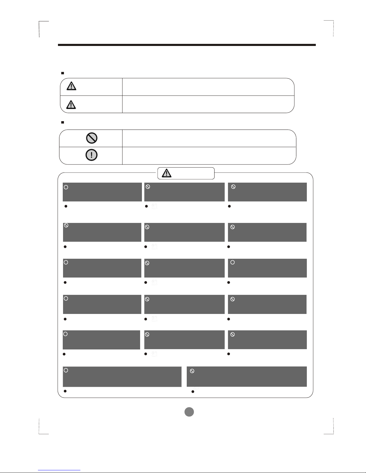
To prevent injury to the user or other people and property damage, the following instructions must be
followed. Incorrect operation due to ignoring of instructions may cause harm or damage.
The seriousness is classified by the following indications.
This symbol indicates the possibility of death or serious injury.
Meanings of symbols used in this manual are as shown below.
WARNING
Always do this.
Never do this.
CAUTION
This symbol indicates the possibility of injury or damage to property.
Connect with the power
properly.
Do not modify power cord
length or share the outlet
with other appliances
Always ensure effective
earthing.
Disconnect the power if
strange sounds, smell, or
smoke comes from it.
Ventilate room before operating air
conditioner if there is a gas leakage from
another appliance.
Otherwise, it may cause electric
shock or fire due to excess heat
generation.
It may cause electric shock or
fire due to heat generation.
No earthing may cause electric
shock.
It may cause fire and electric
shock.
It may cause explosion, fire and, burns.
It may cause electric shock or fire
due to heat generation.
It may cause electric shock.
It may cause failure of machine
or electric shock.
It contains contaminants and
could make you sick.
It may cause fire and electric
shock.
It may cause electric shock or fire.
This could damage your health.
No installation may cause fire
and electric shock.
It may cause electric shock.
It may cause an explosion or fire.
It may cause failure and electric shock.
Do not operate or stop the
unit by switching on or off
the power.
Do not operate with wet
hands or in damp
environment.
Do not allow water to run
into electric parts.
Do not drink water drained
from air conditioner.
Do not use the power cord
close to heating appliances.
Do not damage or use an
unspecified power cord.
Do not direct airflow at
room occupants only.
Always install circuit
breaker and a dedicated
power circuit.
Do not open the unit
during operation.
Do not use the power cord near
flammable gas or combustibles, such
as gasoline, benzene, thinner, etc.
Do not disassemble or modify unit.
!!
!!
!!
!!
!!
WARNING
Use the correctly rated
breaker or fuse.
There is risk of fire or electric
shock.
!!
4
SAFETY PRECAUTIONS
CAUTION
When the air filter is to be
removed, do not touch the
metal parts of the unit.
It may cause an injury.
Do not clean unit when
power is on as it may cause
fire and electric shock, it may
cause an injury.
Operation with windows
opened may cause wetting
of indoor and soaking of
household furniture.
When the unit is to be
cleaned, switch off, and turn
off the circuit breaker.
Stop operation and close
the window in storm or
hurricane.
Use caution when unpacking
and installing. Sharp edges
could cause injury.
Do not clean the air
conditioner with water.
Water may enter the unit and
degrade the insulation. It may
cause an electric shock.
This could injure the pet or
plant.
Do not put a pet or house
plant where it will be
exposed to direct air flow.
Ventilate the room well
when used together
with a stove, etc.
An oxygen shortage
may occur.
Do not use this air conditioner to preserve precision devices, food, pets,
plants, and art objects.
It may cause deterioration
of quality, etc.
It may cause failure of
product or fire.
Do not use for
special purposes.
Turn off the main power
switch when not using
the unit for a long time.
If water enters the
unit, turn the unit off
and disconnect the
power , contact a
qualified service
technician.
!!
!!
!!
!!
!!
!!
!!
It may cause failure of
appliance or accident.
Appearance may be
deteriorated due to change
of product color or
scratching of its surface.
Do not place obstacles
around air-inlets or inside
of air-outlet.
Do not use strong detergent
such as wax or thinner. Use
a soft cloth for cleaning.
If bracket is damaged, there
is concern of damage due to
falling of unit.
There is danger of fire or
electric shock.
Ensure that the installation bracket of
the outdoor appliance is not damaged
due to prolonged exposure.
Do not place heavy object on the
power cord and take care so that
the cord is not compressed.
Operation without filters
may cause failure.
Always insert the filters
securely. Clean filter
once every two weeks.
!!
!!
!!
5
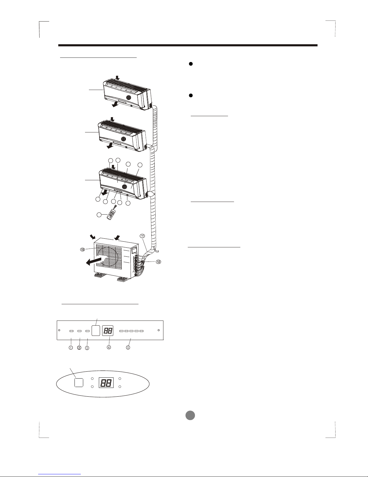
Identification of parts
Outdoor unit
OPERATING INSTRUCTIONS
Indoor unit
Outdoor unit
Indoor unit
IMPORTANT:
For multi-split type air conditioner, one outdoor
unit can match different types of indoor units.
So all the pictures in this manual are for explan ation purpose only. Your air conditioner may be
slightly different. The actual shape shall prevail.
The following pages introduce several kinds of
indoor units matching with the outdoor units.
LED Display panel
Air intake
Air outlet
AUTO indication lamp
Lights up during the Auto operation.
OPERATION indication lamp
This indicator appears only when the compressor
is in operation and indicates the current operating
frequency.
TIMER indication lamp
Lights up during Timer operation.
DEFROST indication lamp
(For Cooling & Heating models only):
Lights up when the air conditioner starts
defrosting automatically or when the warm air
control feature is activated in heating operation.
4
3
5
2
6
1
10
9
7
88
(C)
TEMP
AUTO
COOL
DRY
HEAT
FAN
HIGH
MED
LOW
MODE
FAN SPEED
TIMER ON
SLEEP
ON/OFF
TIMER OFF
AIR
DIRECTION
RESET LOCK
SET TEMPE
RATURE
SWING
LED
DISPLAY
TURBO
Air intake
Air outlet
1. Front panel
2. Top air intake
3. Air filter(Inside)
4. Air outlet
5. Horizontal air flow louver
6. Vertical air flow louver(Internal)
7. Display panel
8. LED display window
9. Remote controller
10. Manual control button(Behind the front panel)
11. Refrigerant connecting pipe, drain hose and
electric wiring
12. Stop valve
13. Air outlet
A1 unit
A2 unit
B unit
DIGITAL DISPLAY indication lamp
Displays the current setting temperature. Only
when the air conditioner is in FAN operation, it
displays the actual room temperature. And displays
the malfunction code or protection code.
.
Display panel
One-two/three type
Signal receptor
AUTO
DEFROST
OPERATION
TIMER
Signal receptor
AUTO TIMER
DEF.
FREQUENCY
(1)
(2)

OPERATING INSTRUCTIONS
Indoor unit
Outdoor unit
1010
DISPLAY PANEL
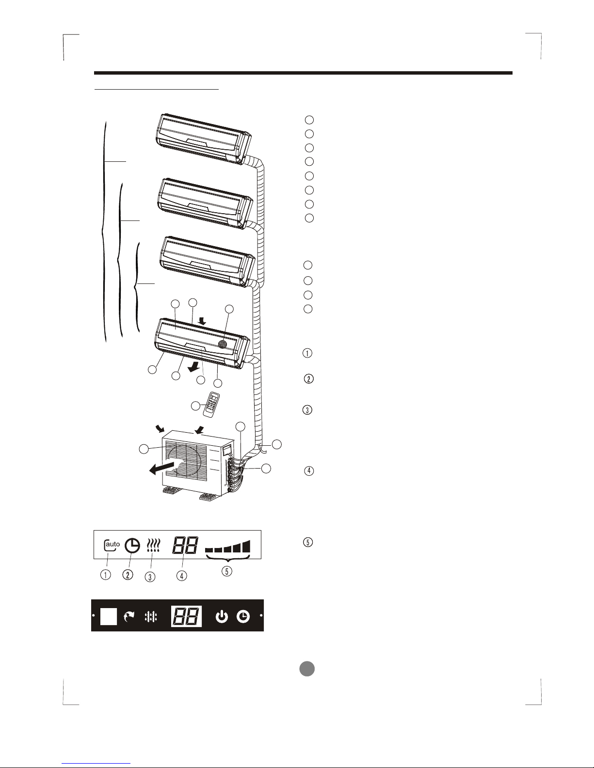
Identification of parts
Indoor unit
Outdoor unit
Air outlet
Air inlet
3
8
7
4
5
6
2
1
One-twin
One-three
One-four
9
1111
1212
1313
Front panel frame
Front panel
Air filter
Horizontal air flow grille
Vertical air flow louver
Room temperature sensor
Display panel
Infrared signal receiver
Remote controller
Drain hose, refrigerant connecting pipe
Connective cable
Stop valve
Fan hood
1
3
4
5
6
7
8
9
10
11
12
2
13
DISPLAY PANEL
OPERATION indicator:
The indicator flashes once every second
after power is on and illuminates when the
air conditioner is in operation.
TIMER indicator:
The indicator illuminates when TIMER is set ON.
PRE-DEF. Indicator (For cooling& heating
model only):
This indicator illuminates when the air conditioner
starts defrosting automatically or when the Anticold air function is activated in heating operation.
AUTO indicator:
This indicator flashes when the air conditioner
is in AUTO operation.
TIMER
OPERATION
PRE-DEF
Infrared signal receptor
6
Infrared signal receptor
OPERATION
TIMER
PRE-DEF
AUTO
(1)
(2)
OPERATING INSTRUCTIONSOPERATING INSTRUCTIONS
Indoor unit
Outdoor unit
LED Display window
Identification of parts
Indoor unit
Outdoor unit
Air outlet
Air in
let
One-twin
One-three
One-four
8
Front panel frame
Front panel
Air filter
Horizontal air flow grille
Vertical air flow louver
Room temperature sensor
Display panel
Remote controller
Drain hose, refrigerant connecting pipe
Connective cable
Stop valve
Fan hood
1
3
4
5
6
7
8
9
10
11
12
2
LED DISPLAY WINDOW
4
3
5
2
6
1
7
9
10
11
12
autoauto
7
AUTO indication lamp
Lights up during the Auto operation.
OPERATION indication lamp
This indicator appears only when the
compressor is in operation and indicates the
current operating frequency.
TIMER indication lamp
Lights up during Timer operation.
DEFROST indication lamp
(For Cooling & Heating models only):
Lights up when the air conditioner starts
defrosting automatically or when the warm air
control feature is activated in heating operation.
DIGITAL DISPLAY indication lamp
Displays the current setting temperature. Only
when the air conditioner is in FAN operation, it
displays the actual room temperature. And
displays the malfunction code or protection
code.
(1)
(2)
OPERATING INSTRUCTIONS
Indoor unit
Outdoor unit
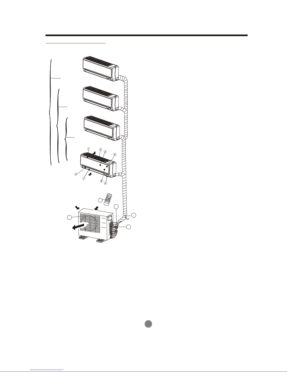
Identification of parts
Indoor unit
Outdoor unit
Air outlet
One-twin
One-three
One-four
9
10. Drain hose, refrigerant connecting pipe
11. Connective cable
12. Stop valve
13. Fan hood
10
11
12
13
In
do
or u
ni
t
Air
ou
tle
t
Air
in
le
t
1. Panel frame
2. Rear air intake grille
3. Front panel
4. Air Purifying filter & Air filter(behind)
5. Horizontal louver
6. LCD display window
7. Vertical louver
8. Manual control button(behind)
9. Remote controller holder
8
 Loading...