

Page 1
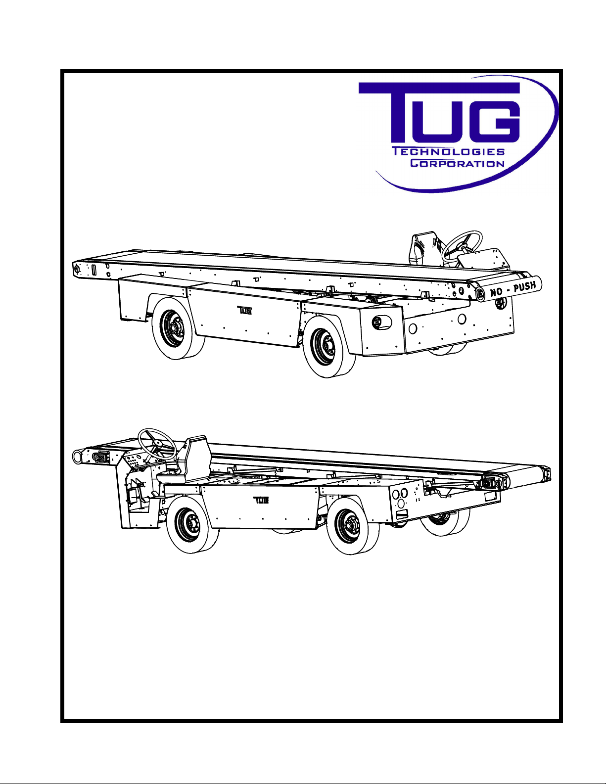
MOBILEBELT
LO ADER
MODEL660&663
OPERATIONMANUAL
Volume1of1
OriginallyIssuedDecember2015
CD397-Oper
Page 2

Mobile Belt Loader Model 660
Operation Manual
Introduction
COPYRIGHTNOTICE
This manual is copyright © 2015 Tug Technologies Corporation (TUG). All rights reserved.
This manual contains confidential and proprietary information.
This document and any information contained herein, may not be reproduced or redistributed in
any form whatsoever without the express, written consent of TUG.
Any attempt to alter the contents of this manual in any way by anyone other than an authorized
agent of TUG shall be construed as copyright infringement and punishment will be pursued under
all applicable laws.
All vendor literature contained in this manual is the copyrighted property of the respective vendors,
protected by the same laws governing this manual.
Introduction - 1 - ii CD397-Oper
Page 3

Introduction
Mobile Belt Loader Model 660
Operation Manual
RECORDOFREVISIONS
Property of: _____________________________________________________________________
Company: _____________________________________________________________________
Address: _____________________________________________________________________
City: _______________________________ State/Province: _____________________
Country: _______________________________ Zip/Postal Code: _____________________
REVISIONDATA
Check each revision received, and insert the revised and supplementary pages in your manual.Tug
Technologies Corporation assumes no liability for personal injury or equipment failure due to any operation performed without heed to manual revisions.
Date of original publication: December 2015
TableIntroduction-1-1:Revisions
RevisionNumber Date BriefDescription
CD397-Oper
Introduction - 1 - iii
Page 4

Mobile Belt Loader Model 660
Operation Manual
Introduction
LISTOFEFFECTIVEPAGES
Only pages that have been revised are listed in Table Introduction - 1 - 2: List of Effective Pages.
Table Introduction- 1-2:ListofEffectivePages
Page Revision Date Page Revision Date
Introduction - 1 - iv
CD397-Oper
Page 5

Introduction
Mobile Belt Loader Model 660
Operation Manual
TABLEOFCONTENTS
Copyright Notice ............................................................................................Introduction - 1 - ii
Record of Revisions ...................................................................................... Introduction - 1 - iii
Revision Data........................................................................................... Introduction - 1 - iii
List of Effective Pages ..................................................................................Introduction - 1 - iv
Table of Contents ...............................................................................................Introduction-1-v
List of Figures ...................................................................................................Introduction-1-xi
List of Tables ................................................................................................... Introduction-1-xiii
Unit Identification ...........................................................................................Introduction - 1 - 1
Model Number ...............................................................................................Introduction - 1 - 2
Warranty Information .....................................................................................Introduction - 1 - 3
Introduction ...............................................................................................Introduction - 1 - 3
Pre-delivery Procedures ...........................................................................Introduction - 1 - 3
Authorization Requirements - Repairs Requiring Prior Approval..............Introduction - 1 - 3
Warranty ........................................................................................................Introduction - 1 - 4
Warranty Statements ................................................................................Introduction - 1 - 4
Warranty Policy And Coverage.................................................................Introduction - 1 - 4
Service Recalls or Owner Notification Programs ................................Introduction - 1 - 4
Warranty Cancellation.........................................................................Introduction - 1 - 5
Warranty Exclusions .................................................................................Introduction - 1 - 5
Warranty Claim Process ...........................................................................Introduction - 1 - 6
Contact TUG Technologies.................................................................Introduction - 1 - 6
Parts....................................................................................................Introduction - 1 - 7
Return Parts........................................................................................Introduction - 1 - 7
Labor ...................................................................................................Introduction - 1 - 7
Aircraft Ground Support Equipment ...............................................................Introduction - 1 - 8
Warranty Policy Statement .......................................................................Introduction - 1 - 8
General Warranty Terms & Conditions .....................................................Introduction - 1 - 8
Warranty Labor Flat Rate Guide ..................................................................Introduction - 1 - 10
Technical Assistance ...................................................................................Introduction - 1 - 17
How to Use This Manual ..............................................................................Introduction - 1 - 19
Safety .......................................................................................................Safety - 1 - 1
Section 1: General Safety Guidelines ................................................................Safety - 1 - 1
1.1 Introduction ....................................................................................................... Safety - 1 - 1
1.2 Standard Safety Features................................................................................. Safety - 1 - 1
1.3 Optional Safety Features .................................................................................. Safety - 1 - 3
1.4 Safety Responsibilities...................................................................................... Safety - 1 - 4
1.5 Operator Safety Responsibility ......................................................................... Safety - 1 - 5
1.6 Mechanic Safety Responsibility ........................................................................ Safety - 1 - 7
1.7 Emergency Procedures .................................................................................... Safety - 1 - 8
1.7.1 Disabled or Stalled Vehicle ...................................................................... Safety - 1 - 8
1.7.1.1 Operational Engine ......................................................................... Safety - 1 - 8
1.7.1.2 Operational Engine - Unable to Move............................................. Safety - 1 - 9
1.7.1.3 Inoperable Engine With Electrical Power...................................... Safety - 1 - 10
1.7.1.4 Inoperable Engine With Loss of Electrical Power ......................... Safety - 1 - 10
1.7.2 Recommended Fire Procedure.............................................................. Safety - 1 - 11
1.7.3 Collisions................................................................................................ Safety - 1 - 12
Section 2: IATA Flightline Safety Guidelines ..................................................Safety - 2 - 13
2.1 IGOM Chapter 4: Aircraft Handling Procedures.............................................. Safety - 2 - 13
CD397-Oper Introduction - 1 - v
Page 6

Mobile Belt Loader Model 660
Operation Manual
Introduction
2.1.1 Ramp Safety in Aircraft Handling........................................................... Safety - 2 - 13
2.2 General Ramp Safety ..................................................................................... Safety - 2 - 13
2.2.1 Danger Areas......................................................................................... Safety - 2 - 13
2.2.2 Engine Intake Area ................................................................................ Safety - 2 - 14
2.2.3 Equipment Restraint Area & Equipment Restraint Line ......................... Safety - 2 - 17
2.2.3.1 FOD - Foreign Object Debris ........................................................ Safety - 2 - 17
2.2.3.2 FOD Checks.................................................................................. Safety - 2 - 18
2.3 Safety Instructions for Operating Motorized Vehicles on Ramp ..................... Safety - 2 - 19
2.3.1 General Safety Instructions for Ground Support Equipment (GSE)....... Safety - 2 - 19
2.3.2 Basic Operating Requirements for GSE ................................................ Safety - 2 - 19
2.3.3 Belt Loader Aircraft Loading Equipment ................................................ Safety - 2 - 20
2.3.4 Ground Support Equipment Safety Driving and Parking Inside ERA..... Safety - 2 - 21
2.4 Adverse Weather Conditions .......................................................................... Safety - 2 - 21
2.4.1 Winter or Slippery Apron Conditions...................................................... Safety - 2 - 21
2.4.2 Thunderstorms....................................................................................... Safety - 2 - 22
2.4.3 High Wind Conditions ............................................................................ Safety - 2 - 22
2.5 ISO 7000 and 7010 Safety Guidelines............................................................ Safety - 2 - 22
2.5.1 International Decals and Symbols. ........................................................ Safety - 2 - 22
Material Data Safety Sheet Information ............................................................... Safety - 2 - 25
2.5.2 Links for products:.................................................................................. Safety - 2 - 26
Operation ...........................................................................................Operation - 1 - 1
Section 1: System Overview ........................................................................ Operation - 1 - 4
1.1 Safety Precautions.......................................................................................Operation - 1 - 4
1.2 Purpose of Equipment .................................................................................Operation - 1 - 4
1.3 General Description .....................................................................................Operation - 1 - 4
1.4 Major Components.......................................................................................Operation - 1 - 4
1.4.1 Power Package...................................................................................Operation - 1 - 4
1.4.2 Engine.................................................................................................Operation - 1 - 4
1.4.2.1 Gasoline and LPG - Ford 2.5L ...................................................Operation - 1 - 4
1.4.2.2 Diesel - Deutz 2.9L.....................................................................Operation - 1 - 5
1.4.3 Transmission.......................................................................................Operation - 1 - 5
1.4.4 Drive Shaft ..........................................................................................Operation - 1 - 5
1.4.5 Drive Axle............................................................................................Operation - 1 - 5
1.4.6 Steer Axle ...........................................................................................Operation - 1 - 5
1.4.7 Brakes.................................................................................................Operation - 1 - 5
1.4.7.1 Hydraulic ....................................................................................Operation - 1 - 5
1.4.7.2 Park Brake .................................................................................Operation - 1 - 5
1.4.8 Chassis ...............................................................................................Operation - 1 - 5
1.4.9 Body....................................................................................................Operation - 1 - 5
1.4.10 Conveyor...........................................................................................Operation - 1 - 6
1.4.11 Operator’s Compartment ..................................................................Operation - 1 - 6
1.4.12 Electrical System ..............................................................................Operation - 1 - 7
1.4.13 Hydraulic System ..............................................................................Operation - 1 - 7
1.4.13.1 General Hydraulics Operation..................................................Operation - 1 - 7
1.4.13.2 Steer and Braking ....................................................................Operation - 1 - 7
1.4.13.3 Lift Cylinders and Conveyor Motor...........................................Operation - 1 - 8
Section 2: Operational Procedures ........................................................... Operation - 2 - 11
2.1 Instrument Panel Controls and Indicators..................................................Operation - 2 - 11
2.1.1 Ford 2.5L...........................................................................................Operation - 2 - 11
2.1.2 Deutz 2.9L Tier 4F ............................................................................Operation - 2 - 11
Introduction - 1 - vi CD397-Oper
Page 7

Introduction
Mobile Belt Loader Model 660
Operation Manual
2.1.3 Maneuvering Controls.......................................................................Operation - 2 - 15
2.1.4 Conveyor Controls ............................................................................Operation - 2 - 16
2.1.5 Electrical Supply ...............................................................................Operation - 2 - 17
2.1.6 Preliminary Checks ...........................................................................Operation - 2 - 17
2.1.7 Maneuvering Procedures..................................................................Operation - 2 - 18
2.1.7.1 Engine Start Procedure (Gas)..................................................Operation - 2 - 18
2.1.7.2 Engine Start (Diesel)................................................................Operation - 2 - 19
2.1.7.3 Release parking brake. ............................................................Operation - 2 - 19
2.1.7.4 Transmission Drive (FWD/REV) Selection...............................Operation - 2 - 19
2.1.7.5 Depress foot throttle.................................................................Operation - 2 - 20
2.1.7.6 Maneuver vehicle with steering wheel. ....................................Operation - 2 - 20
2.1.7.7 Maneuvering the baggage loader around the aircraft ..............Operation - 2 - 21
2.1.8 Belt Loader Towing Instructions........................................................Operation - 2 - 21
2.1.8.1 Towing Requirements ..............................................................Operation - 2 - 21
2.1.9 Conveyor Safety Props .....................................................................Operation - 2 - 23
2.2 IATA...........................................................................................................Operation - 2 - 24
2.3 SAE............................................................................................................Operation - 2 - 24
2.4 ISO EMC Evaluation..................................................................................Operation - 2 - 24
2.5 ISO Product Safety Evaluation ..................................................................Operation - 2 - 25
2.6 Locations of Technical Construction Files .................................................Operation - 2 - 25
Section 3: Specifications ........................................................................... Operation - 3 - 27
3.1 General Specifications of the 660..............................................................Operation - 3 - 27
3.1.1 Dimensions .......................................................................................Operation - 3 - 27
3.2 Torque Values............................................................................................Operation - 3 - 28
3.2.1 Metric Fasteners ...............................................................................Operation - 3 - 28
3.2.2 Graded Bolts .....................................................................................Operation - 3 - 29
3.3 Performance ..............................................................................................Operation - 3 - 31
3.3.1 Specifications....................................................................................Operation - 3 - 31
3.3.2 Environmental Operating Limits........................................................Operation - 3 - 32
3.3.3 Environmental Vibration Information.................................................Operation - 3 - 32
3.3.4 Environmental Sound Information.....................................................Operation - 3 - 32
3.4 Engines......................................................................................................Operation - 3 - 35
3.4.1 Gasoline............................................................................................Operation - 3 - 35
3.4.1.1 Ford MSG-425 2.5L .................................................................Operation - 3 - 35
3.4.2 Diesel ................................................................................................Operation - 3 - 35
3.4.2.1 Deutz D2.9L .............................................................................Operation - 3 - 35
3.5 Transmission..............................................................................................Operation - 3 - 36
3.5.1 Gear Ratios.......................................................................................Operation - 3 - 36
3.6 Standard Conveyor Heights and Angles....................................................Operation - 3 - 37
3.7 Compatible Aircraft ....................................................................................Operation - 3 - 38
3.8 Fluids .........................................................................................................Operation - 3 - 42
3.9 Coolant.......................................................................................................Operation - 3 - 43
3.10 Recommended Spare Parts.....................................................................Operation - 3 - 43
3.11 Safety Features........................................................................................Operation - 3 - 44
3.11.1 Shifter / Parking Brake Safety.........................................................Operation - 3 - 44
3.11.2 Shifter Guard...................................................................................Operation - 3 - 44
3.11.3 Neutral Safety Start Switch .............................................................Operation - 3 - 44
3.11.4 Anti-Restart Ignition Switch.............................................................Operation - 3 - 44
3.11.5 Engine Control Module (ECM) Starter Protection ...........................Operation - 3 - 45
3.11.5.1 Ford 2.5L................................................................................Operation - 3 - 45
CD397-Oper Introduction - 1 - vii
Page 8

Mobile Belt Loader Model 660
Operation Manual
Introduction
3.11.5.2 Deutz 2.9L..............................................................................Operation - 3 - 45
3.11.6 Emergency Stop Switch..................................................................Operation - 3 - 45
3.11.7 Park Brake ......................................................................................Operation - 3 - 45
3.11.8 Pilot-Operated Hydraulic Check Valves..........................................Operation - 3 - 45
3.11.9 Safety Props ...................................................................................Operation - 3 - 46
3.11.10 Side / Hand Rails ..........................................................................Operation - 3 - 46
3.11.11 Finger Guards ...............................................................................Operation - 3 - 46
3.11.12 Rubber Bumper Roll .....................................................................Operation - 3 - 46
3.11.13 Steel Hoop Guard (Optional) ........................................................Operation - 3 - 46
3.11.14 Grit Paper......................................................................................Operation - 3 - 46
Section 4: Shipping .................................................................................... Operation - 4 - 47
4.1 Shipping Preparation .................................................................................Operation - 4 - 47
4.1.1 Fuel Tank Preparation .....................................................................Operation - 4 - 47
4.1.2 Battery Preparation ..........................................................................Operation - 4 - 47
4.1.3 Pre-shipping Verification ..................................................................Operation - 4 - 47
4.2 Receiving ...................................................................................................Operation - 4 - 48
4.2.1 Preparing for Operation ....................................................................Operation - 4 - 48
4.2.1.1 Battery......................................................................................Operation - 4 - 48
4.2.1.2 Emergency Hydraulic Pump.....................................................Operation - 4 - 48
4.2.1.3 Radiator....................................................................................Operation - 4 - 48
4.2.1.4 Fuel Cell...................................................................................Operation - 4 - 48
Section 5: Storage ...................................................................................... Operation - 5 - 49
5.1 Short Term Storage ...................................................................................Operation - 5 - 49
5.1.1 Gasoline Engine................................................................................Operation - 5 - 49
5.1.1.1 Ford 2.5 L Engine.....................................................................Operation - 5 - 49
5.1.1.2 Transmission............................................................................Operation - 5 - 49
5.1.1.3 Drive Axle.................................................................................Operation - 5 - 49
5.1.1.4 Tires .........................................................................................Operation - 5 - 50
5.1.1.5 Lubrication................................................................................Operation - 5 - 50
5.1.1.6 Battery......................................................................................Operation - 5 - 50
5.1.1.7 Fluid Levels..............................................................................Operation - 5 - 50
5.1.2 Diesel Engine....................................................................................Operation - 5 - 50
5.1.2.1 Deutz 2.9L Engine....................................................................Operation - 5 - 50
5.1.2.2 Transmission............................................................................Operation - 5 - 50
5.1.2.3 Drive Axle.................................................................................Operation - 5 - 50
5.1.2.4 Tires .........................................................................................Operation - 5 - 51
5.1.2.5 Lubrication................................................................................Operation - 5 - 51
5.1.2.6 Battery......................................................................................Operation - 5 - 51
5.1.2.7 Fluid Levels..............................................................................Operation - 5 - 51
5.2 Returning the Vehicle to Operation After Short Term Storage...................Operation - 5 - 51
5.2.1 Tires ..................................................................................................Operation - 5 - 51
5.2.2 Battery...............................................................................................Operation - 5 - 51
5.2.3 Engine...............................................................................................Operation - 5 - 52
5.2.4 Transmission.....................................................................................Operation - 5 - 52
5.3 Long Term Storage....................................................................................Operation - 5 - 52
5.3.1 Gasoline Engine................................................................................Operation - 5 - 52
5.3.1.1 Ford 2.5L Engine......................................................................Operation - 5 - 52
5.3.1.2 Engine Exterior.........................................................................Operation - 5 - 53
5.3.2 Transmission.....................................................................................Operation - 5 - 53
5.3.2.1 Drive Axle.................................................................................Operation - 5 - 54
Introduction - 1 - viii CD397-Oper
Page 9

Introduction
Mobile Belt Loader Model 660
Operation Manual
5.3.3 Tires ..................................................................................................Operation - 5 - 54
5.3.4 Lubrication ........................................................................................Operation - 5 - 54
5.3.5 Fluid Levels.......................................................................................Operation - 5 - 54
5.3.6 Battery...............................................................................................Operation - 5 - 54
5.3.7 Diesel Engine....................................................................................Operation - 5 - 55
5.3.7.1 Deutz 2.9L Engine ...................................................................Operation - 5 - 55
5.3.8 Transmission.....................................................................................Operation - 5 - 56
5.3.9 Drive Axle..........................................................................................Operation - 5 - 56
5.3.10 Exhaust ...........................................................................................Operation - 5 - 57
5.3.11 Tires ................................................................................................Operation - 5 - 57
5.3.12 Lubrication ......................................................................................Operation - 5 - 57
5.3.13 Levels..............................................................................................Operation - 5 - 57
5.3.14 Wheel Bearings...............................................................................Operation - 5 - 57
5.3.15 Battery.............................................................................................Operation - 5 - 57
5.3.16 Fuel System ....................................................................................Operation - 5 - 58
5.3.17 Engine Exterior ...............................................................................Operation - 5 - 58
5.3.18 Tagging ...........................................................................................Operation - 5 - 59
5.4 Returning the Vehicle to Operation After Long-Term Storage...................Operation - 5 - 59
5.4.1 Tires ..................................................................................................Operation - 5 - 59
5.4.2 Battery...............................................................................................Operation - 5 - 59
5.4.3 Engine...............................................................................................Operation - 5 - 59
5.4.4 Transmission.....................................................................................Operation - 5 - 60
5.4.5 Drive Axle..........................................................................................Operation - 5 - 60
5.4.6 Pre-Operational Checks....................................................................Operation - 5 - 60
5.5 Cold Weather Storage ...............................................................................Operation - 5 - 60
5.6 Returning the Vehicle to Operation After Cold Weather Storage...............Operation - 5 - 61
5.6.1 Refill Fluids .......................................................................................Operation - 5 - 61
CD397-Oper Introduction - 1 - ix
Page 10

Mobile Belt Loader Model 660
Operation Manual
Introduction
THIS PAGE INTENTIONALLY BLANK
Introduction - 1 - x CD397-Oper
Page 11

Introduction Mobile Belt Loader Model 660
Operation Manual
LISTOFFIGURES
Figure Introduction - 1 - 1 - TUG Identification Plate .........................................Introduction-1-1
Figure Introduction - 1 - 2 - Model Numbers ......................................................Introduction-1-2
Figure Safety - 2 - 1 - Idle Power - Engine Intake Area NO Zone............................. Safety-2-15
Figure Safety - 2 - 2 - Breakaway Power - Engine Blast Area NO Zone .................. Safety-2-16
Figure Safety - 2 - 3 - Equipment Restraint Area...................................................... Safety-2-17
Figure Safety - 2 - 4 - Fasten Seat Belts (White on Blue Background)..................... Safety-2-24
Figure Safety - 2 - 5 - Use Hearing Protection (White on Blue Background)............ Safety-2-24
Figure Safety - 2 - 6 - Hot Surface (Yellow Field with Black Border) ........................ Safety-2-25
Figure Operation - 2 - 1 - Instrument Panel - Ford 2.5L.......................................Operation-2-12
Figure Operation - 2 - 2 - Instrument Panel - Deutz 2.9L.....................................Operation-2-14
Figure Operation - 2 - 3 - Maneuvering and Conveyor Controls..........................Operation-2-16
Figure Operation - 2 - 4 - Conveyor Controls.......................................................Operation-2-17
Figure Operation - 2 - 5 - Belt Loader with Props Engaged.................................Operation-2-23
Figure Operation - 3 - 1 - Capscrew Examples....................................................Operation-3-28
Figure Operation - 3 - 2 - Sound - Engine Idle - Conveyor Down - Belt Stationary .....................
.............................................................................................................................Operation-3-33
Figure Operation - 3 - 3 - Sound - Engine Max - Conveyor Down - Belt Max Speed ..................
.............................................................................................................................Operation-3-33
Figure Operation - 3 - 4 - Sound - Engine Idle - Conveyor Up - Belt Stationary..Operation-3-34
Figure Operation - 3 - 5 - Sound - Engine Max - Conveyor Up - Belt Max Speed.......................
.............................................................................................................................Operation-3-34
Figure Operation - 3 - 6 - Conveyor - Full Down Rear, Full Up Front ..................Operation-3-37
Figure Operation - 3 - 7 - Conveyor - Full Up Rear, Full Up Front.......................Operation-3-37
Figure Operation - 3 - 8 - Conveyor - Full Down Rear, Full Down Front..............Operation-3-38
Figure Operation - 3 - 9 - Conveyor - Full Up Rear, Full Down Front ..................Operation-3-38
CD397-Oper Introduction-1-xi
Page 12

Mobile Belt Loader Model 660
Operation Manual
Introduction
THIS PAGE INTENTIONALLY BLANK
Introduction-1-xii CD397-Oper
Page 13

Introduction Mobile Belt Loader Model 660
Operation Manual
LISTOFTABLES
Table Introduction - 1 - 1: Revisions ................................................................. Introduction-1-iii
Table Introduction - 1 - 2: List of Effective Pages ............................................. Introduction-1-iv
Table Introduction-1-1: Service Recalls/Notification ...........................................Introduction-1-4
Table Introduction-1-2: Flat Rate Labor Guide .................................................Introduction-1-10
Table Safety-1-1: Standard Safety Equipment ........................................................... Safety-1-1
Table Safety-1-2: Optional Safety Equipment............................................................. Safety-1-3
Table Safety-1-3: Operator Safety Responsibilities.................................................... Safety-1-5
Table Safety-1-4: Mechanic Safety............................................................................. Safety-1-7
Table Safety-2-1: Examples of FOD......................................................................... Safety-2-18
Table Safety-2-2: FOD Checks................................................................................. Safety-2-18
Table Operation-2-1: Instrument Panel Description - Ford 2.5L..........................Operation-2-12
Table Operation-2-2: Instrument Panel Description - Deutz 2.9L........................Operation-2-14
Table Operation-3-1: Dimensions and Measurements ........................................Operation-3-27
Table Operation-3-2: Torque Values for Metric Fasteners ..................................Operation-3-28
Table Operation-3-3: Torque Values for Graded Bolts ........................................Operation-3-29
Table Operation-3-4: Performance Data..............................................................Operation-3-31
Table Operation-3-5: Specification Data.............................................................Operation-3-31
Table Operation-3-6: Environmental Limits .........................................................Operation-3-32
Table Operation-3-7: Ford MSG-425 (2.5 L).......................................................Operation-3-35
Table Operation-3-8: Deutz D2.9L.......................................................................Operation-3-35
Table Operation-3-9: Gear Ratios........................................................................Operation-3-36
Table Operation-3-10: Conveyor Positions..........................................................Operation-3-38
Table Operation-3-11: Aircraft Compatibility........................................................Operation-3-39
Table Operation-3-12: Hydraulic Fluid................................................................Operation-3-42
Table Operation-3-13: Engine Oil .......................................................................Operation-3-42
Table Operation-3-14: Fluids ...............................................................................Operation-3-42
CD397-Oper Introduction-1-xiii
Page 14

Mobile Belt Loader Model 660
Operation Manual
Introduction
THIS PAGE INTENTIONALLY BLANK
Introduction-1-xiv CD397-Oper
Page 15
Introduction
SERIAL
NUMBER
3,175
3,266
40
907
227500
2,000
25
7,200
7,000
KILOGRAMS
POUNDS
KILOGRAMS
POUNDS
660−4−3728
KPH
KILOGRAMS
KILOGRAMS
MPH
POUNDS
POUNDS
MAXIMUM SINGLE LOAD ON THE BOOM IS
PERMISSABLE TOTAL PAYLOAD EVENLY DISTRIBUTED ON THE BOOM AT MAXIMUM AND MINIMUM ANGLE IS:
MAXIMUM SPEED
WITH CAB
UNLADEN WEIGHT w/OUT CAB
MFG DATE
MODEL #
TUG TECHNOLOGIES CORPORATION
1995 DUNCAN DRIVE
KENNESAW, GEORGIA 30144
Mobile Belt Loader Model 660
Operation Manual
UNITIDENTIFICATION
The information and instructions in this manual are intended to acquaint the operator with the
important operating features of the TUG Mobile Belt Loader Model 660. The various controls,
gauges, switches, and operating features are explained and illustrated throughout this manual.
Personnel responsible for operation of the vehicle should read this manual carefully.
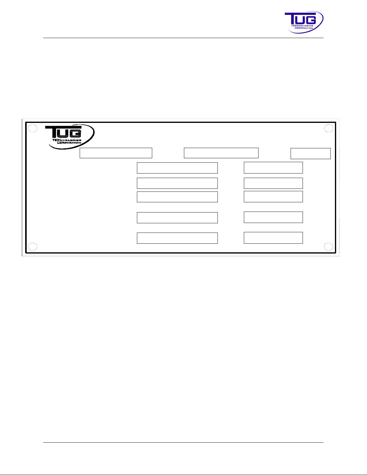
To aid the technician in repair or service work on this unit, a TUG identification plate is located in
the operator's compartment.
FigureIntroduction-1-1:TUGIdentificationPlate
The serial number identification of each unit will appear on the nameplate along with the date of
manufacture. The mailing address of TUG is also located at the top of the data plate opposite
the TUG logo. This necessary information will ensure the customer a fast and accurate response
to any parts and/or service request.
Please verify the serial number on the identification nameplate of the unit and enter your unit
serial number here:
If applicable, enter your company identification number here:
______________________________________________________________________
______________________________________________________
CD397-Oper Introduction - 1 - 1
Page 16
Mobile Belt Loader Model 660
660 44
Conveyor Variations
660 = 34 in Wide x 24 ft Long
663 = 31.5 in. Wide x 24 ft Long
Engine Variations
28 = Ford MSG-425 (2.5 L) 4 Cylinder Gasoline/LP
44 = Deutz TCD 2.9 L Diesel Tier IV Final
_
Conveyor Engine
Model Number Coding
660 44
Conveyor Variations
660 = 34 in Wide x 24 ft Long
663 = 31.5 in. Wide x 24 ft Long
Engine Variations
28 = Ford MSG-425 (2.5 L) 4 Cylinder Gasoline/LP
44 = Deutz TCD 2.9 L Diesel Tier IV Final
_
Conveyor Engine
Model Number Coding
Operation Manual
MODELNUMBER
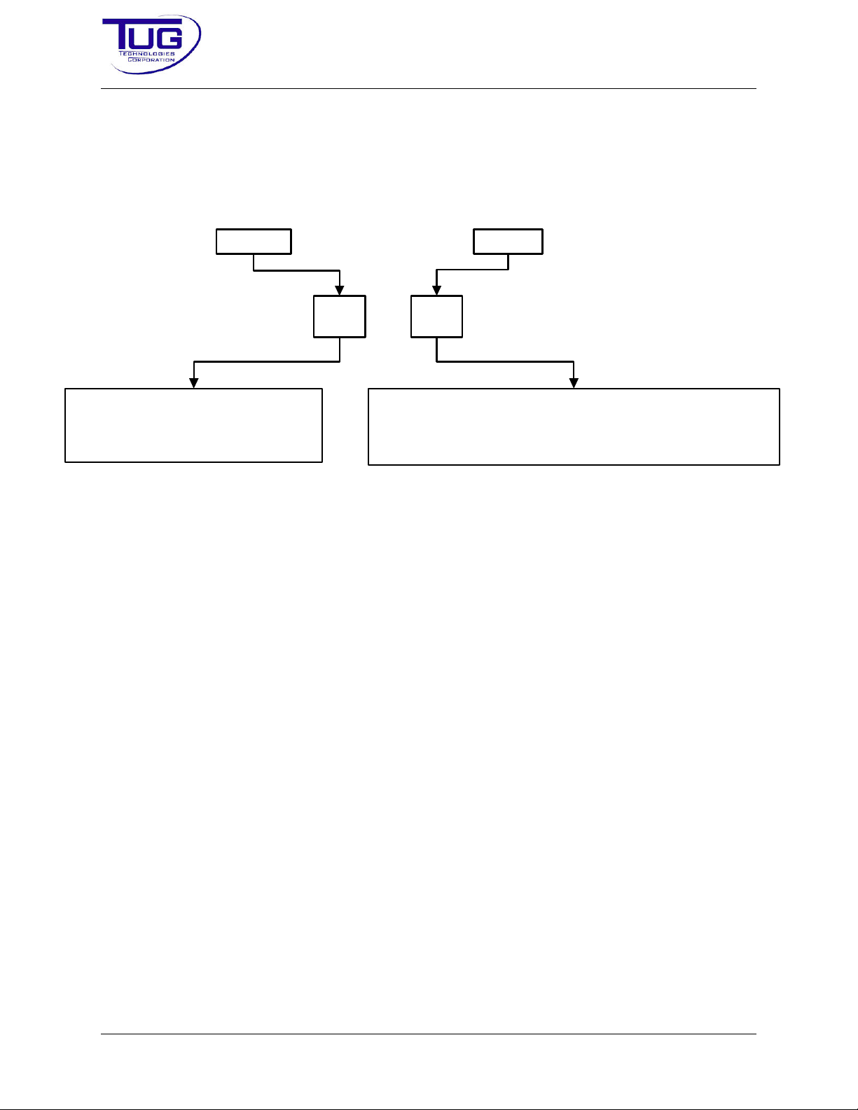
Tug numbers models according to the diagram in Figure Introduction - 1 - 2 Model Numbers.
Introduction
FigureIntroduction-1-2:ModelNumbers
Introduction - 1 - 2 CD397-Oper
Page 17

Introduction Mobile Belt Loader Model 660
Operation Manual
WARRANTYINFORMATION
INTRODUCTION
The primary goal of warranty adjustment is to satisfy our customers. Every satisfied customer
strengthens the components of our whole organization - all aspects of the products themselves
and the service that backs them up. This manual is directed to TUG Technologies’ distributors
and customers of TUG Equipment. It should be used to implement the Warranty Program at
every level.
This Warranty Policy and Procedures Manual includes the warranties of TUG Technologies’
products. It explains warranty policy and coverage, and describes the warranty claim process.
TUG Technologies is responsible for handling warranty and policy adjustments promptly and in
accordance with the provisions of the Sales and Service Agreement, TUG Technologies Warranty Statements and this manual. Customers who recognize the manual as the "heart" of the
warranty system and train their personnel in its use may expect service personnel qualified to
submit claims that are properly completed and fully-substantiated, resulting in prompt claims payment.
NOTE:
The guidelines and requirements in this manual apply to warranty claims submitted to TUG Technologies for reimbursement to the customer.
PRE-DELIVERYPROCEDURES
Establish pre-delivery procedures that ensure the appropriate inspections and adjustments are
made prior to equipment being placed in service.
AUTHORIZATIONREQUIREMENTS-REPAIRSREQUIRINGPRIORAPPROVAL
Certain repairs and claims require prior approval. Any repair which will take more then 2 hours
labor to complete must have prior approval.
CD397-Oper Introduction - 1 - 3
Page 18

Mobile Belt Loader Model 660 Introduction
Operation Manual
WARRANTY
A warranty is a specific document that guarantees the quality of goods to a purchaser within a
specified length of time and according to usage limitations. The TUG Technologies warranty
statement defines the conditions of the warranty. A warranty:
1. Remains in force for the specified period, provided that an occurrence has not taken
place to render the warranty inapplicable.
2. Assures the owner that if, under the conditions specified, a defect in factory workmanship
or material is encountered, it will be corrected at no charge or on a prorata basis.
3. Extension of coverage by any manufacturer does not change what is covered in the
basic, expressed limited warranty.
WARRANTYSTATEMENTS
TUG Technologies Warranty Statements provide detailed information regarding coverage and
usage limitations for TUG products.
WARRANTYPOLICYANDCOVERAGE
ServiceRecallsorOwnerNotificationPrograms
TUG TECHNOLOGIES may establish a program to resolve extensive customer concern about a
component beyond warranty coverage. Owners are notified to contact TUG Technologies for
replacement/repair. Customers will be notified by TUG TECHNOLOGIES with information that:
• Identifies the component and condition.
• Outlines the inspection and repair procedure required to correct the condition.
• Defines reimbursement.
Table Introduction-1-1:ServiceRecalls/Notification
Component Disposition
Shipment TUG will ship components for service recalls and / or approved warranty
claims free of charge.
Freight Charges Return of recalled components is covered when shipped via the prepaid
RGA tag or another approved, least-expensive method.
Labor for Service Reimbursed at the approved hourly warranty labor rate.
Non-TUG Parts Only covered with prior approval from TUG.
Introduction - 1 - 4 CD397-Oper
Page 19

Introduction Mobile Belt Loader Model 660
Operation Manual
WarrantyCancellation
Certain situations cause a warranty to be canceled. Examples of such situations include, but are
not limited to:
• Damaged due to accidents.
• Damage due to abuse, improper operation or poor maintenance practices.
Total or partial warranty cancellation is registered in TUG Technologies’ records.
WARRANTYEXCLUSIONS
The following items are examples of some of the non-reimbursable items under the Warranty and
Policy Program. Non-reimbursable repairs include:
• Any repair to a unit on which the mileage/hours or date of first use reported has been misrepresented.
• Any repair to a unit on which the odometer / hour meter has been altered so that the true
mileage / hours cannot be determined.
NOTE:
• Any repair for which the date on the order has been misrepresented or altered to place an
out-of-warranty component within the warranty provisions.
• Any repair made to a product that has been misused or mistreated, or upon which a conversion, modification, or installation of a non-TUG part has been made affecting the performance, reliability or stability of a part.
NOTE:
• Parts handling charges.
• Parts damaged due to accident.
This item applies only to cases in which mileage / hours are a condition of the
warranty.
Any failure to a TUG-supplied part resulting from such action is not covered by
the warranty.
The warranty on parts damaged because of accident or an act of nature will be
canceled.
NOTE:
CD397-Oper Introduction - 1 - 5
Repairs on accident claims or conditions that could have contributed to personal injury or property damage must not begin until approval is obtained. Do
not scrap allegedly defective parts that may have contributed to injury or damage until written approval is received.
Page 20

Mobile Belt Loader Model 660 Introduction
Operation Manual
• Repairs required because of inadequate or incorrect protection in storage and / or preparation for storage.
• Repairs of damage or failure caused by poor outside workmanship.
• Any repair operation that changes the existing specifications of the equipment or component.
• Repair techniques beyond the appropriate shop manual limits.
• Labor performed by anyone other than an authorized TUG technician without prior
approval, unless the situation is an emergency.
• Use of any other than genuine TUG parts, unless used in an emergency.
• A second or subsequent repair or adjustment necessitated by an incomplete or improper
original repair or adjustment.
• Adjustments made to improve appearance or performance beyond normal standards.
• Maintenance and normal replacement of service items. For example, replacement of filters and fluids, tightening of bolts, nuts, or fittings. Minor, labor-only repairs are reimbursable.
• Any repair to a part that is found not to be defective.
• Replacement of assembly rather than repair if replacement costs exceed repair costs,
and parts are available. Replacement requires prior approval.
• Labor operations such as additional diagnostic time, abnormal accessibility or diagnosis
time, hot testing and testing of new parts after repair. Standard labor allowances are
included in warranty labor time standards.
• Replacement parts damaged in shipment (carrier responsibility).
• Towing expense or transportation for moving equipment between the customer's location
and the repair location.
WARRANTYCLAIMPROCESS
NOTE:
No warranty invoice will be accepted unless TUG Technologies has been contacted prior to the start of work being done to the unit.
ContactTUGTechnologies
Phone: 1-800-989-8499 Ext. 1 or 770-422-8021
Email (preferred): [email protected]
Introduction - 1 - 6 CD397-Oper
Page 21

Introduction Mobile Belt Loader Model 660
Operation Manual
To expedite the claim process please provide the following information:
1. Unit S/N
2. Hours of operation
3. Description of problem or symptoms
4. List of parts required for repairs
5. Shipping address
6. Contact name
7. Contact phone number(s)
Parts
TUG Technologies will ship warranty parts at no charge once the claim has been received and
accepted.
ReturnParts
Not all failed parts need to be returned to TUG Technologies. If parts are to be returned, an RGA
tag will be sent with the replacement warranty parts. The tag must be filled out completely and
attached to the return part(s).
NOTE:
TUG Technologies reserves the right to invoice for parts being returned for the reasons but not
limited to the reasons listed below.
• If deemed caused by an unwarrantable failure.
• If part is damaged due to inadequate packaging.
• Part was not supplied by TUG Technologies
• Proper documentation was not provided or sent back with faulty part.
Parts not returned within 30 days of claim will be charged to your account.
Labor
TUG Technologies will reimburse labor based on the Standard Labor Rate Chart. Any work which
will exceed the times outlined in this chart requires prior approval. All warranty labor is subject to
TUG Technologies Warranty Approval Process.
CD397-Oper Introduction - 1 - 7
Page 22

Mobile Belt Loader Model 660 Introduction
Operation Manual
AIRCRAFTGROUNDSUPPORTEQUIPMENT
WARRANTYPOLICYSTATEMENT
This Policy Statement sets forth the terms of the warranty provided by TUG Technologies Corp.
with respect to ground power units, air start units, tow tractors, cargo tractors and other equipment sold for use in the commercial aviation industry (“Aircraft Ground Support Equipment”
“Industrial”).
The foregoing warranty gives Buyer specific legal rights that may vary from state to state. Some
states do not permit the limitation of incidental or consequential damages or limitation of remedies under warranties. The above limitations apply only to the extent permitted by applicable law.
GENERALWARRANTYTERMS&CONDITIONS
TUG Technologies warrants that each new item of equipment is of good workmanship and is free
of mechanical defects, provided that:
1. The equipment is installed and operated in accordance with the TUG Technologies Operation and Maintenance Manual.
2. The equipment is used under normal operating conditions, for which it was designed.
3. The equipment is not subject to misuse, negligence, or accident.
4. The equipment is properly maintained by qualified technicians in accordance with the
TUG Technologies Operation and Maintenance Manual.
This warranty expires, unless otherwise agreed by TUG Technologies in a special provision, 24
months after being shipped or after 2000 operating hours. TUG Technologies warranty does not
apply to fluids, oils, fuses, bulbs, accumulators, paint, seals, tires, bumpers, brakes, or wearable
parts, bulbs, batteries, etc.
All warranty claims must be sent to the warranty department for processing. All information pertaining to specific claim must be provided for claim to be processed in a timely manner.
All the expenses related to a warranty claim will be invoiced to the buyer until TUG Technologies
has evaluated the claim. Whatever the circumstances, the buyer should not refuse or delay the
payment. If the evaluation concludes as TUG’s full responsibility, a credit will be issued in the
favor of the buyer.
This warranty is extended by TUG Technologies only to the buyer of new products from TUG
Technologies or its authorized distributors. The products purchased under this warranty are
intended for use exclusively by the buyer. There shall be no third party beneficiary of this warranty.
Under no circumstances whatsoever shall TUG Technologies be liable for any special or consequential damages, whether based on lost goodwill, lost resale profits, work stoppage, impairment
of other goods or otherwise, and whether arising out of breach of any express or implied war-
Introduction - 1 - 8 CD397-Oper
Page 23

Introduction Mobile Belt Loader Model 660
Operation Manual
ranty, breach of contract, negligence, or otherwise, except in the case of personal injury as may
be required by applicable law.
The warranty is automatically void by TUG Technologies in the following cases:
1. The product has received some modification not authorized or completed according to
TUG Technologies requirements.
2. Some original parts have been replaced by parts not provided by TUG Technologies.
CD397-Oper Introduction - 1 - 9
Page 24

Mobile Belt Loader Model 660 Introduction
Operation Manual
WARRANTYLABORFLATRATEGUIDE
Table Introduction-1-2, “Flat Rate Labor Guide,” lists the labor rates for various task.
Table Introduction-1-2:FlatRateLaborGuide
Part Hours
R&RCoolingSystem
Fan 0.2
Radiator, Transfer Shroud 0.5
Top or Bottom Hose 0.5
Heater Hose 1.0
Water Pump 1.5
Thermostat 0.5
R&RControls
Shifter 1.0
Shifter Cable & Adjust 1.0
Neutral Safety Switch 0.5
Adjust Neutral Safety Switch 0.5
Park Brake Link 1.0
Accelerator Cable & Adjust 1.0
Accelerator Pedal, Hookup, & Adjust 0.5
R&RDriveAxle&Mounting
Axle Assembly 4.0
Input Seal 0.5
Input Flange 0.5
Axle Shaft Seal 1.5
Shaft O-Ring Seal
Axle Shaft & Axle Bearing 1.0
R&RDriveShaft
Drive Shaft 1.0
One U Joint 0.5
Introduction - 1 - 10 CD397-Oper
Page 25

Introduction Mobile Belt Loader Model 660
Operation Manual
Table Introduction-1-2:FlatRateLaborGuide(Continued)
Part Hours
Body
Repaint 8.0
Repaint Cab 2.0
R&RBrakes
Master Cylinder & Bleed 1.5
Brake Booster 1.0
Adjust Brake Booster
Hard Brake Lines & Bleed 1.5
Master Cylinder Cover Gasket 0.2
Brake Pedal 0.5
Brake Return Spring 0.2
Hub Front 1.0
One Stud 1.0
Park Brake Cable to Rear Wheels / Linkage 1.0
Axle Shaft Leak 1.5
Brake Wheel Cylinder 2.0
R&RBrakes,FrontAxle
Caliper & Bleed 1.0
Rotor 1.0
Wheel Bearings 1.0
Wheel Stud 1.0
Cab(Option-CallforStandardRates)
R&RElectrical
Troubleshoot Short or No Power 2.0
Coolant Temp Sensor 0.5
Coolant Gauge 0.5
CD397-Oper Introduction - 1 - 11
Page 26

Mobile Belt Loader Model 660 Introduction
Operation Manual
Table Introduction-1-2:FlatRateLaborGuide(Continued)
Part Hours
Hour Meter 0.5
Ammeter 0.5
Electric Fuel Gauge 1.0
Electric Fuel Sender 1.0
Kysor Coolant Temp Sensor 0.5
Kysor Oil Pressure Sensor 0.5
Kysor Override Switch 0.5
Light Switch 0.5
Battery Cable 0.5
Wire Harness 5.0
Kysor Warning Light 0.5
Start Relay 0.5
Horn 0.3
Horn Relay 0.3
Battery 0.3
Turn Signal Light 0.3
Turn Signal Flasher 0.3
Tighten Battery Cable 0.3
Glow Plug Switch 0.3
Brake Switch 0.3
Adjust Brake Switch
R&REngine
Starter Relay 0.3
Starter 1.0
Alternator 1.0
Fuel Pump or Lift Pump 1.0
Battery 0.5
Valve Cover Gasket 1.0
Introduction - 1 - 12 CD397-Oper
Page 27

Introduction Mobile Belt Loader Model 660
Operation Manual
Table Introduction-1-2:FlatRateLaborGuide(Continued)
Part Hours
Spark Plug Wires 0.5
Engine Assembly 7.0
Oil Pan 2.0
Front Crankshaft Seal 2.0
R&RExhaust
Exhaust Pipe 0.5
Muffler 0.5
Tai l P i pe 0.5
R&RFrontSuspension&Steering
Front Spring 1.0
Front Axle and Transfer Springs 1.5
Tie Rod End & Adjust Toe In 0.5
King Pin 1.0
Drag Link 0.5
Pitman Arm - Gas 0.5
Pitman Arm - Diesel 0.5
Steer Cylinder 1.0
Steer Hose - Valve to Cylinder 0.5
Steer Pump 1.0
Steer Hose - Pump to Valve 0.5
Steer Sector 1.0
Steering Wheel 0.5
Horn Button Kit 0.5
Steer Valve 1.5
Upper Steering Bearing 0.5
Steering Wheel 0.3
CD397-Oper Introduction - 1 - 13
Page 28

Mobile Belt Loader Model 660 Introduction
Operation Manual
Table Introduction-1-2:FlatRateLaborGuide(Continued)
Part Hours
R&RFuelSystem
Fuel Cell 2.5
Fuel Line Steel 0.5
LP Lock Off Valve 1.0
LP Regulator 1.0
Miscellaneous
Install Rubber Bumper 1.0
R&R Hood Latch 0.3
Install Decal 0.3
R&RSeating
Seat Frame 0.5
Bucket Seat 0.3
R&RTransmission
Transmission 3.0
Transmission Front Oil Seal - Gas 3.0
Transmission Rear Oil Seal 1.0
Modulator Valve 0.3
Modulator Cable 0.8
Pan Gasket & Refill1.0
Shifter Interlock Solenoid 0.5
Shifter Interlock Brake Switch 0.5
R&RConve yor
Troubleshoot Conveyor Electrical 2.0
Switch-in Box 0.5
Control Relay 0.5
Relay Under Instrument Panel 0.5
Conveyor Kill Button 0.5
Introduction - 1 - 14 CD397-Oper
Page 29

Introduction Mobile Belt Loader Model 660
Operation Manual
Table Introduction-1-2:FlatRateLaborGuide(Continued)
Part Hours
Conveyor Kill Switch 0.5
Conveyor Kill Switch Wiring Harness 0.5
Electric Eyes 0.5
Glow Plug Relay 0.5
R&RHydraulics
Hydraulic Pump 1.0
Hydraulic Pump Pulley 0.5
Main Manifold 1.0
Steering, Brakes Relief, & Adjustment Valve 0.5
2-Lever Valve Under Seat 1.0
Valve Lever 0.3
Relief Valve Under Seat 1.0
Main Hydraulic Pressure Relief Valve 0.5
Repair Hydraulic Leak 0.5
Electric Control Valve Assembly 1.0
Conveyor Hydraulic Motor 1.5
Conveyor Drive Roller Chain 0.5
Hoses Through Lift Arm to Conveyor 0.5
Hoses to Lift Cylinder
Front or Rear Lift Cylinder 2.0
Cylinder Holding Valve 1.0
Front Lift Arm 2.5
Rear Lift Arm 1.5
Small Manifold Valve Under Front of Conveyor 1.0
Adjust Conveyor Reverse Direction Holding Valve 1.0
Direction Valve Under Conveyor 1.0
Front or Manual Controls 1.0
Repair Direction Valve Spool Seal 1.0
CD397-Oper Introduction - 1 - 15
Page 30

Mobile Belt Loader Model 660 Introduction
Operation Manual
Table Introduction-1-2:FlatRateLaborGuide(Continued)
Part Hours
Hydraulic Tank 2.0
Drain and Refill Hydraulic Tank 1.0
R&RConve yor
Conveyor Belt 2.5
Front Drive Roller (Includes Belt) 3.0
Front Drive Roller Bearing (Includes Belt) 3.0
Front Drive Roller Sprocket 3.0
Rear Idler Roller (Includes Belt) 3.0
Rear Idler Roller Bearing (Includes Belt) 3.0
Rear Idler Roller Bearing Adjusting Rod 3.0
Crowder Roller 3.0
Crowder Roller Bearings 3.0
Conveyor Roller 3.0
Conveyor Control Rod - Rear Part 3.0
Conveyor Control Rod - Front Part 3.0
Conveyor Control Detent 0.5
Conveyor Valve Control Arm 1.0
Adjust Belt Speed Control Link at Accelerator Pedal 0.5
Front Finger Guard 0.5
Front Roll Bumper 0.5
Introduction - 1 - 16 CD397-Oper
Page 31

Introduction Mobile Belt Loader Model 660
Operation Manual
TECHNICALASSISTANCE
Direct any questions concerning the operation of the 660 Mobile Belt Loader to:
TUG Technologies Corporation
1995 Duncan Dr.
Kennesaw, GA 30144
USA
Email: [email protected]
Direct any questions concerning parts for the 660 Mobile Belt Loader to:
Parts Department
USA: 1-800-989-8499
International: 00 + 1 + (770) 422-8021
Fax: 1-770-422-8730
Email: [email protected]
Direct any questions concerning sales of the 660 Mobile Belt Loader to:
Equipment Sales
Phone: (770) 422-7230
Fax: (770) 428-7315
Email: [email protected]
Direct any questions concerning warranty for the 660 Mobile Belt Loader to:
Warranty Department
Phone: (770) 422-8021
Toll Free: (800) 989-8499
Fax: 770-422-8730
Email: [email protected]
All information in this manual is based on the latest production information available at the time of
publication.
Direct any questions concerning the contents or format of this manual to:
Technical Publications
Email: [email protected]
CD397-Oper
Introduction - 1 - 17
Page 32

Mobile Belt Loader Model 660
Operation Manual
THIS PAGE INTENTIONALLY BLANK
Introduction - 1 - 18 CD397-Oper
Page 33
Introduction Mobile Belt Loader Model 660
Operation Manual
HOWTOUSETHISMANUAL
NOTE:
This manual contains an introduction, safety information, and one chapter. Refer to the Table of
Contents at the front of this manual and in the chapter for details of content.
The page numbering system in this manual is a three-part number. The first number represents
the chapter in which the page appears, the second number indicates the section within that chapter, and the third number is the page number within that chapter.
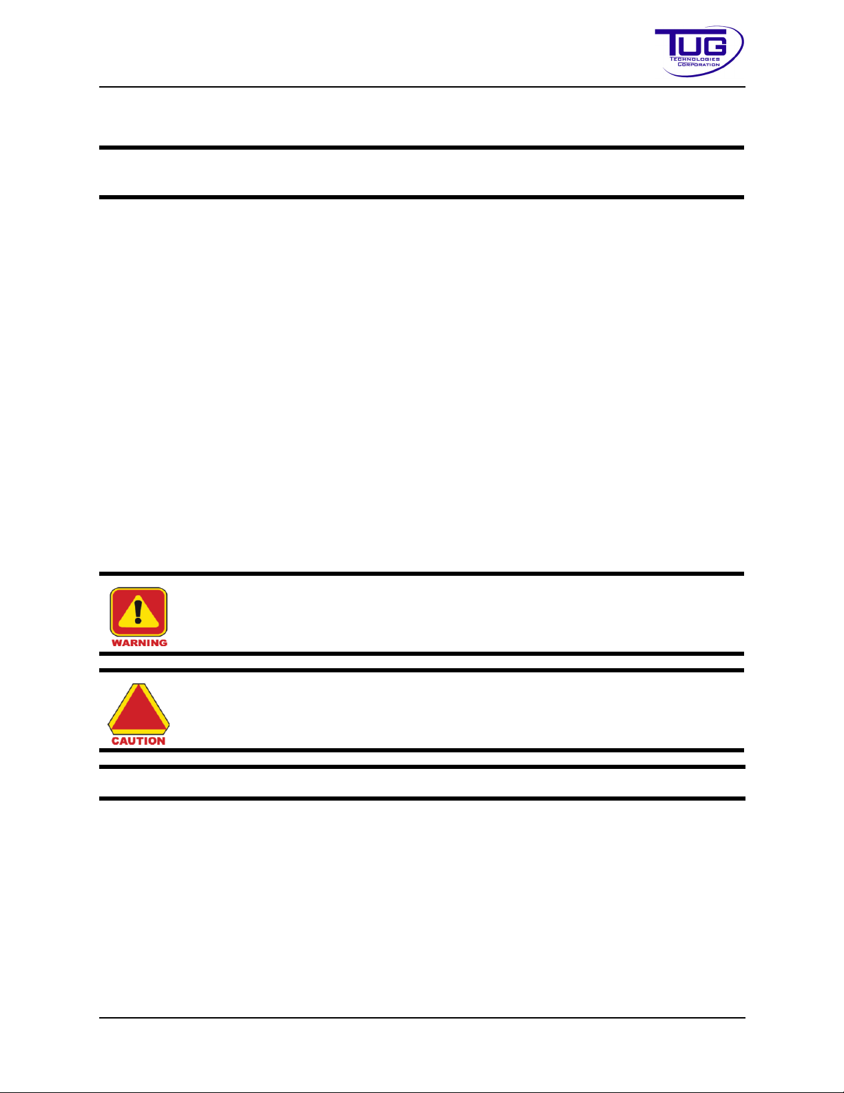
The following symbols are examples of the Warnings, Cautions, and Notes used in this manual.
These Warnings, Cautions, and Notes will appear immediately prior to the procedure.
• The WARNING provides notice of potential safety issues that could, if ignored, result in
• The Caution provides notice of potential safety issues that could, if ignored, result in
• Notes highlight issues or specific information that should be paid particular attention to
Important Notice: TUG recommends that the vehicle operator thoroughly study the
contents of this manual before attempting to operate the vehicle.
serious personal injury or, possibly, death.
damage to equipment.
allow for an error-free procedure or provides important information concerning the procedure.
NOTE:
WARNING: SAFETY NOTES THAT MUST BE FOLLOWED TO AVOID SERIOUS INJURY TO PERSONNEL OR EVEN DEATH.
CAUTION: Safety notes that need to be followed to prevent damage to equipment.
Important non-hazard information for the user.
CD397-Oper Introduction - 1 - 19
Page 34

Mobile Belt Loader Model 660 Introduction
Operation Manual
THIS PAGE INTENTIONALLY BLANK
Introduction - 1 - 20 CD397-Oper
Page 35

Safety Mobile Belt Loader Model 660
Operation Manual
Safety
Section1:GeneralSafetyGuidelines
1.1Introduction
Operator and mechanic safety is important at TUG. During the design and production of every
product, a thorough safety review of all components is standard operating procedure. As a result
of this review, safety warnings, cautions, and notes are provided throughout this manual. It is
important that operators and mechanics become familiar with all of these safety requirements.
To reinforce this action, this part of the manual has been devoted to safety.
CAUTION: Every operator and mechanic involved with this equipment must
read and abide by this safety section.
The safety part of this manual covers the following:
• Introduction
• Standard Safety Features
• Optional Safety Items
• Operator Safety Responsibility
• Mechanic Safety Responsibility
• IATA Flightline Safety Guidelines
It is strongly recommended that this chapter be reproduced and bound in the operator’s book,
along with your station safety rules.
1.2StandardSafetyFeatures
The following safety features are standard.
Table Safety-1-1:StandardSafetyEquipment
No. Equipment
1 Recessed headlights
Combination tail and stop lights
3 Back-up lights
CD397-Oper Safety - 1 - 1
Page 36

Mobile Belt Loader Model 660 Safety
Operation Manual
TableSafety-1-1:StandardSafetyEquipment(Continued)
No. Equipment
4 Turn signals with Hazard Warnings
5 Dual independent brake systems with brake warning light
6 Power-boosted front disc brakes and rear drum brakes
7 Adjustable over-center park brake hand lever
8 Lighted transmission shift control
9 Shift control with hand throttle interlock
10 Transmission shift lever guard
11 Neutral only start switch in shifter control
12 Angled right front corner
13 Ease of maneuverability
14 Center of steering wheel operated horn
15 Labeled controls
16 Left front driver position for excellent visibility
17 Conveyor lifting emergency pump
18 Conveyor safety props
19 Hydraulic steering
20 Pilot pressure operated cylinder holding valves
21 Pilot pressure operated reverse belt holding valve
22 Belt drive cushion valve
23 Hydraulic system pressure designed at 1500 psi (10.34 MPa or 102.07 atm) max.
24
All hydraulic hoses rated at 3250 psi (22.41 MPa or 221.15 atm). Always use OEM
hoses during replacement
25 Lagged belt driving roller
26 Hand and / or Guide Rails on either side of the conveyor
27 Non-slip fender surfaces
28 Boot cutouts in rear bumper for safe access to belt as walkway
29 Bolted down hydraulic tank and battery cover
30 Retracting Seat belts
Safety - 1 - 2 CD397-Oper
Page 37

Safety Mobile Belt Loader Model 660
Operation Manual
TableSafety-1-1:StandardSafetyEquipment(Continued)
No. Equipment
31
Independent expanding shoe and drum park brake on transmission output shaft or
in rear axle
32 Non slip covering on floor board
33 Non slip surface on brake and accelerator pedal
34
High coolant temperature/low oil pressure shutdown (Ford 2.5L only) (optional on
other engines)
1.3OptionalSafetyFeatures
The following table contains a list of optional safety items.
Tabl e Safety-1-2:OptionalSafetyEquipment
No. Items
1 Backup alarm
2 Amber flashing light
3 Amber strobe light
4 Mud and snow tires
5 Work lights
6 Reflective striping
7 Engine kill E-Stop buttons on conveyor and instrument panel
8 Conveyor up/down movement alarm
Transmission neutral only and park brake applied safety circuit for belt conveyor
9
movement interlock (Must be in neutral, park brake applied for conveyor to operate)
10 Gap filler strip between conveyor belt and front rubber bumper
11 Rubber bumper roll across the rear of the conveyor frame
12 Steel hoop guard across the rear of the conveyor frame
13 Cooling fan cover
14 Alternator belt
15 Manifold cover
CD397-Oper Safety - 1 - 3
Page 38

Mobile Belt Loader Model 660 Safety
Operation Manual
1.4SafetyResponsibilities
General rules cannot be written to cover every possible situation that may arise with each job
function, task, or procedure. Therefore, certain definite responsibilities rest with the individual.
These responsibilities include:
• Protection of yourself
• Protection of fellow employees
• Proper care of tools and equipment.
Report:
• unsafe conditions
• unsafe equipment
• unsafe operation
to the proper authorities. If unsure of an operating procedure, consult your supervisor for guidance.
Safety - 1 - 4 CD397-Oper
Page 39

Safety Mobile Belt Loader Model 660
Operation Manual
1.5OperatorSafetyResponsibility
WARNING: DO NOT DRIVE A BELT LOADER WITH DEFECTIVE BRAKES,
STEERING, TIRES, HORN, PARKING BRAKE, CONVEYOR BELT, OR
LIGHTS. COMMUNICATE THESE PROBLEMS TO YOUR SUPERVISOR.
NOTE:
No. Operator Responsibility
1 Use proper hearing protection.
2 Follow training provided by your company.
3
4 Keep hands and feet away from rotating parts and tires.
5 Wear secure clothing.
6 Bring belt loader to a complete halt and set parking brake before dismounting.
Follow station safety rules. If you do not have a written list of safety rules, ask for one
prior to operating this belt loader.
TableSafety-1-3:OperatorSafetyResponsibilities
Check before operating belt loader:
•Lights
•Brakes
• Parking Brake
• Steering
•Horn
•Tires
• Conveyor Belt for damaged or raised hooks
7 Use seat belts at all times when belt loader is in motion.
Do not shift transmission into gear with engine above idle speed. Keep foot off accel-
8
erator when shifting.
Bring belt loader to a complete stop before shifting from reverse to drive or from drive
9
to reverse.
Check the path is clear behind the belt loader prior to driving in reverse direction.
10
11
12
CD397-Oper Safety - 1 - 5
• Check local station rules and, if allowed, blow horn before reversing
• If not permitted, follow station rules for alerting other personnel prior to backing.
Use caution when in congested areas and around blind corners and rows of carts. Be
alert for other equipment and personnel.
Never operate at speeds inconsistent with operating conditions. Limit speed to allow
adequate time for braking in an emergency.
Page 40

Mobile Belt Loader Model 660 Safety
Operation Manual
TableSafety-1-3:OperatorSafetyResponsibilities(Continued)
No. Operator Responsibility
13
Do not allow the belt loader to be pushed by other equipment or use the belt loader to
push other equipment. Use proper towing equipment.
14 Do not tamper with engine.
15
Do not use the belt loader as a hoist for other personnel. Use proper equipment for
personnel.
16 Do not walk on fenders when icy or wet.
17
Walk ONLY on the conveyor and not on the painted frame. The painted frame is slippery when wet.
18 Do not ride on the belt, conveyor, or fenders.
19
In event of a malfunction, stop operations and move the loader to a safe area, if possible, then notify a supervisor.
20 Do not stand on the belt when it is moving.
21 Use handrails when walking on the conveyor belt.
22 Keep hands, feet, and clothing away from the underside of the conveyor.
23 Do not put hands underneath the conveyor.
24 Do not wear rings on fingers when using the conveyor belt.
25
26
Check that the chain guards and finger guard at the rear roller are secured and the finger guard is adjusted as close to the roller as possible.
Know and understand the conveyor belt control stations operation, especially the “E”
Stops.
27 Do not insert the conveyor through the cargo door.
28 Do not approach the aircraft when personnel are present in the doorway.
29 Operate at creep speed when approaching aircraft or within 20 ft. of aircraft.
30
Always approach aircraft with the conveyor in the lowered position. Stop five feet from
the aircraft, raise the conveyor as required and creep into position.
31 Do not exceed 2000 pounds (907.2 kg) of weight on the conveyor belt.
32 Carry no passengers unless a seat with seatbelt is provided.
33
Work stations are at the right rear and left front of the conveyor (other locations
optional).
Safety - 1 - 6 CD397-Oper
Page 41

Safety Mobile Belt Loader Model 660
Operation Manual
1.6MechanicSafetyResponsibility
WARNING: ALWAYS USE THE SAFETY PROPS WHEN WORKING UNDER
THE CONVEYOR.
Table Safety-1-4:MechanicSafety
No. Mechanic Safety
1 Keep hands and clothing away from rotating parts
2 Wear secured clothing
3 Use the conveyor safety prop whenever working under conveyor
4 Allow engine to cool before adjusting the alternator belt or hydraulic pump belt
5 Keep hands. gloves, and clothing clear of cooling fan
6 Disconnect the battery positive cable when working on or under the conveyor
7 Do not substitute throttle return springs with lighter or other springs
8 Check brakes and fill master cylinder with DOT3 brake fluid.
If belt tracking, stop the belt while making adjustments on the left front corner, since the
9
drive chain is in that area. The other three corners can be adjusted with the belt running,
but keep hands out from under conveyor.
Inspect seat belts and attachment points regularly. Replace if damaged. Do not bleach or
10
red-dye seat belts, clean with soap and water.
11 Visually check for hydraulic leaks. Do not use hands or fingers to locate leaks
12 Verify all E Stops are functional
13 Check horns and lights
14 Check neutral start only switch for proper adjustment and operation.
15 Check tire and wheel condition, especially proper inflation pressures
16 Torque lug nuts to 125 ft-lbs (169.5 Nm).
17 Use proper lifting equipment when removing or replacing heavy components.
When working underneath belt loader, ensure it is properly supported on secure jack
18
stands that are rated. Do not rely on hydraulic jacks to support the belt loader.
If the belt loader is on a hydraulic or air-operated lift, make sure to place safety support
19
or jack stands in position prior to working under the belt loader.
20 Use a proper transmission jack when removing or replacing the transmission.
CD397-Oper Safety - 1 - 7
Page 42
Mobile Belt Loader Model 660 Safety
Operation Manual
TableSafety-1-4:MechanicSafety(Continued)
No. Mechanic Safety
Jack the drive wheels off the floor and support the belt loader with rated jack stands
21
when troubleshooting the drive system.
22 Take nothing for granted when safety of the vehicle or operator is at stake.
23 Keep good maintenance records.
WARNING: DO NOT REMOVE THE RADIATOR CAP WHEN HOT! SERIOUS
BURNS MAY RESULT. ALLOW TIME TO COOL.
1.7EmergencyProcedures
CAUTION: Every operator and mechanic involved with this equipment must
read and understand emergency procedures prior to operation.
It is the operator’s responsibility to safeguard the unit and others when the unit or trailer is disabled or in a collision. The following emergency procedures describe recommended steps to
follow, in the ev e n t of mechanical breakdown or equipment malfunction. Apply and/or adapt
these procedures to your company’s/station’s emergency procedures as necessary.
WARNING: IN CASE OF AN EMERGENCY - APPLY E-STOP TO DISABLE THE
VEHICLE. THE UNIT IS COMPLETELY INOPERABLE WHEN THE E-STOP
PUSH-BUTTON IS ENGAGED. FAILURE TO COMPLY MAY RESULT IN
DEATH, SERIOUS INJURY, OR PROPERTY DAMAGE.
1.7.1DisabledorStalledVehicle
The Model 660 is equipped with an emergency hydraulic pump activated from the operator’s station actuated b y a spring-loaded two-position switch. This e m e r g e n c y pump supplies
hydraulic pressure for t h e service brake and steering.
1.7.1.1OperationalEngine
When the engine is operational and the unit can be moved, perform the following steps:
1. Move the unit as far away from the traffic area as safely possible.
Safety - 1 - 8 CD397-Oper
Page 43

Safety Mobile Belt Loader Model 660
Operation Manual
2. Turn on the emergency hazard warning signals.
CAUTION: Turn on headlights when/if visibility is limited.
3. If unable to move the tow tractor out of the traffic area and when visibility is limited, set out
one type of emergency warning device (i.e. red cones, etc.) to the front and rear of the
unit.
1.7.1.2OperationalEngine-UnabletoMove
When the engine is operable but the unit cannot be moved, perform the following steps:
1. Use a tow bar to attach the disabled unit to an operational tow tractor.
2. Release the park brake.
3. Ensure steering is operational in the disabled unit by turning the steering wheel.
NOTE:
The disabled unit should be steered to follow the towing unit.
CAUTION: CAUTION: Towing speed must NOT exceed 6 mph (10 km/h). Do
NOT tow the disabled unit more than 6 mi. (10 km).
4. Tow unit.
5. Once towing destination is reached, place transmission of the towing vehicle in neutral,
apply the park brake, and turn the ignition key to the OFF position.
6. Chock wheels of the disabled unit.
7. Disconnect the vehicles by removing the tow bar.
CD397-Oper Safety - 1 - 9
Page 44
Mobile Belt Loader Model 660 Safety
Operation Manual
1.7.1.3InoperableEngineWithElectricalPower
When the engine is inoperable it will experience loss of power.
1. Release the park brake.
CAUTION: Engaging the emergency hydraulic pump for more than one minute will cause the electric motor to overheat. If emergency procedures cannot be completed within one minute, disengage and allow the pump to cool
for at least 10 minutes before re-engaging. Failure to comply may result in
vehicle damage.
2. Engage the emergency hydro-steering pump by holding the toggle switch. Release the
toggle switch to disengage or shut off the hydro-steering pump.
3. Ensure steering is operational in the disabled unit by turning the steering wheel.
NOTE:
4. Tow unit.
5. Once towing destination is reached, place transmission of the towing vehicle in neutral,
6. Chock wheels of the disabled unit.
7. Disconnect the vehicles by removing the tow bar.
Steer the disabled unit to follow the towing unit.
CAUTION: Towing speed must NOT exceed 3 mph (5 km/h). Do NOT tow the
disabled unit more than 6 mi. (10 km).
apply the park brake and turn the ignition key to the OFF position.
1.7.1.4InoperableEngineWithLossofElectricalPower
An inoperable engine will experience loss of electrical power. When there is not enough electrical
power to engage the emergency steering pump, perform the following steps:
1. Use a tow bar to attach the disabled unit and an operational tow tractor.
2. Release the park brake.
CAUTION: Towing speed must NOT exceed 3 mph (5 km/h). Do NOT tow the
disabled unit more than 6 miles (10 km). The disabled unit will be difficult to
steer as there is no hydraulic pressure available.
Safety - 1 - 10 CD397-Oper
Page 45
Safety Mobile Belt Loader Model 660
Operation Manual
3. Tow unit.
4. Once towing destination is reached, place transmission of the towing vehicle in neutral,
apply the park brake and turn the ignition key to the OFF position.
5. Chock wheels of the disabled unit.
6. Disconnect the vehicles by removing the tow bar.
1.7.2RecommendedFireProcedure
WARNING: HAZARD EXISTS WHEN REFUELING AND DEFUELING THE
TRACTOR - NO SMOKING, NO OPEN FLAMES, NO ELECTRICAL DEVICE
OPERATIONS.
Operators should know how to prevent fires and have a basic understanding of fire-fighting techniques. Some common causes of vehicle fires are as follows:
• Operating with low pressure tires.
• Overheated brakes.
• Leaking exhaust system.
• Leaking fuel system.
• Carelessly placed emergency flares or lamps.
• Short circuits in the electrical system
Following are recommended basic steps to perform when a fire occurs. Apply and/or adapt these
procedures in accordance with your company’s/station’s procedures as circumstances warrant.
1. Stop the unit in a safe position away from buildings and other vehicles.
2. Notify the appropriate emergency contacts (as outlined in your company’s/station’s emergency policies and procedures) and inform them what type of fire is burning.
NOTE:
Use all extinguishers according to the manufacturer’s instructions.
3. Based on type of fire, take all possible steps to extinguish the fire using the unit’s fire
extinguisher without endangering yourself or others.
4. If the fire is thought to be due to a short-circuit, engage the battery disconnect button.
CD397-Oper Safety - 1 - 11
Page 46

Mobile Belt Loader Model 660 Safety
Operation Manual
1.7.3Collisions
WARNING: IN A COLLISION, INJURIES, POSSIBLE FUEL LEAKS, OR DAMAGE TO THE VEHICLE CAN OCCUR.
Every operator must take precautions to prevent collisions. If a collision occurs, remain calm and
perform the following steps:
1. Refer and adhere to your company’s/station’s emergency policies and procedures.
WARNING: IN CASE OF A FUEL LEAK - NO SMOKING, NO OPEN FLAMES,
NO ELECTRICAL DEVICE OPERATIONS.
2. All engines of units involved in the collision should be turned off.
3. Notify emergency personnel and supervisory personnel as outlined in your company’s/
station’s emergency policies and procedures.
Safety - 1 - 12 CD397-Oper
Page 47

Safety Mobile Belt Loader Model 660
Operation Manual
Section2:IATAFlightlineSafetyGuidelines
2.1IGOMChapter4:AircraftHandlingProcedures
This section of the TUG Operators Manual has been created from the IATA ground Operations
Manual (IGOM). This section provides general guidelines for GSE handling, including safety procedures. The ground support equipment operator must always follow the training and equipment
operating rules of their employer.
2.1.1RampSafetyinAircraftHandling
Ramp safety rules and procedures promote safe ground handling. Therefore, the minimum
safety rules and procedures defined in this section shall always be applied and understood by all
personnel working on the ramp.
Aircraft damage can endanger passengers, employees, and aircraft. Disruptions may also negatively impact safe airline operations.
Even a slight scratch or dent on an aircraft may result in a serious accident. If you observe or
cause any aircraft damage, you MUST report it. Refer to the operating airline’s policy regarding
reporting of aircraft damage.
2.2GeneralRampSafety
2.2.1DangerAreas
Blast damage or injury from an aircraft engine’s exhaust or intake is very dangerous. The risk is
further increased when an aircraft comes to a stop and then re-applies the additional thrust
required to “break away” and continue taxiing.
Vehicles and personnel must remain clear of aircraft danger areas when aircraft engines are running and/or the anti-collision lights are on.
In order to prevent incidents and accidents caused by aircraft engines, you must never position
yourself or equipment in the following critical areas before or during aircraft departure and arrival:
• Engine Intake Area
• Engine Blast Area
• Propeller Rotation Area (where applicable)
NOTE:
The length of these areas vary for each aircraft type based on whether the engines
are IDLE or BREAKAWAY thrust.
Refer to each aircraft type specific manual for applicable distances and the Company’s instructions for guidance. Ground personnel and loose equipment must stay clear of the intake and
blast areas.
CD397-Oper Safety - 2 - 13
Page 48

Mobile Belt Loader Model 660 Safety
Operation Manual
2.2.2EngineIntakeArea
Make sure the engine intake area is clear:
• At arrival, until the engines have been switched off and are spooling down
• At departure or just before pushback
• At all times while engines are running.
• It is forbidden to pass through the blast area while engines are running.
Refer to the operating airline’s Ground Operation Manual (GOM) for distances applicable to the
specific aircraft type involved in the operation.
Sample Engine Danger Area for A330-300 and A330-200 aircraft are shown in Figure Safety - 2 1 and Figure Safety - 2 - 2.
Safety - 2 - 14 CD397-Oper
Page 49
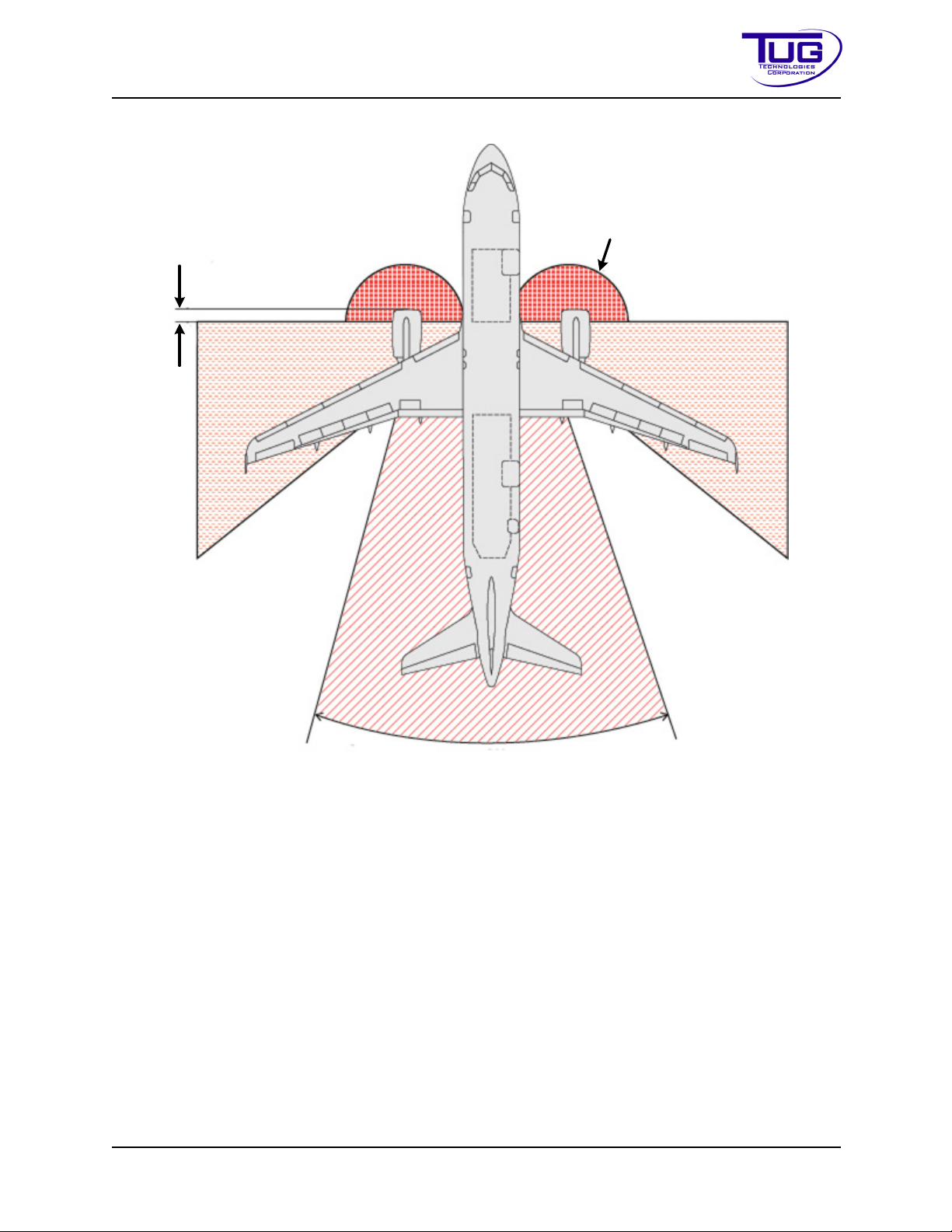
Safety Mobile Belt Loader Model 660
10 ft. (3m)
3.75 ft. (1m)
250 ft. (75m)
30°
Operation Manual
FigureSafety-2-1:IdlePower-EngineIntakeAreaNOZone
CD397-Oper Safety - 2 - 15
Page 50
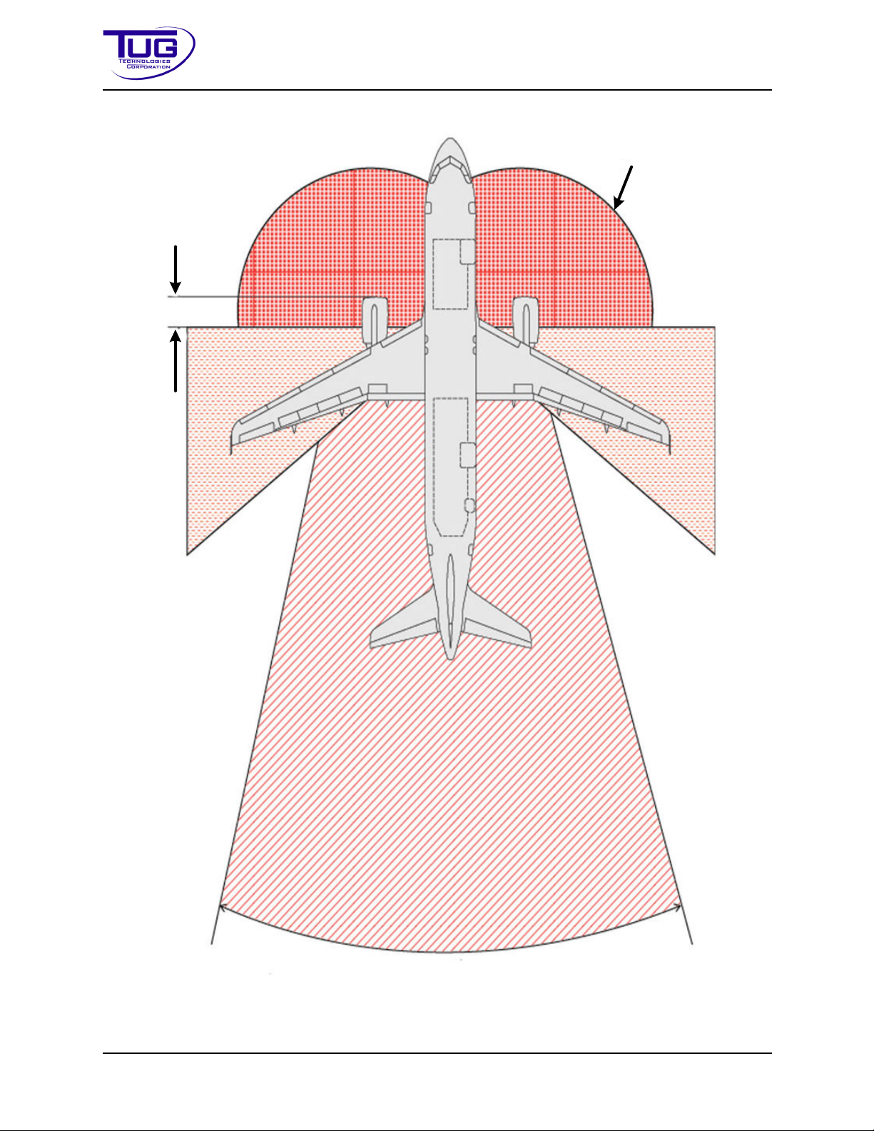
25 ft. (8m)
8 ft. (2.4m)
500 ft.
(150m)
30°
Mobile Belt Loader Model 660 Safety
Operation Manual
FigureSafety-2-2:BreakawayPower-EngineBlastAreaNOZone
Safety - 2 - 16 CD397-Oper
Page 51
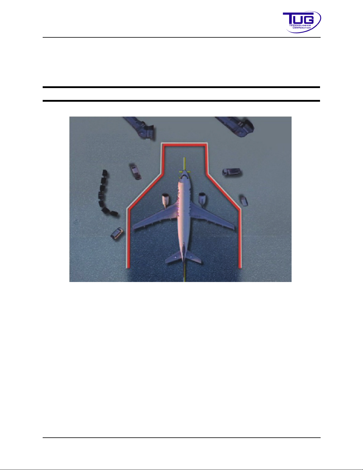
Safety Mobile Belt Loader Model 660
Operation Manual
2.2.3EquipmentRestraintArea&EquipmentRestraintLine
The Equipment Restraint Area (ERA) is defined as the area of the apron bordered by a red line
known as the Equipment Restraint Line, or otherwise indicated, in which an aircraft is parked
during ground operations.
NOTE:
The illustration below provides an example of the markings used in some locations.
If no markings exist, local procedures must establish safe parking areas.
FigureSafety-2-3:EquipmentRestraintArea
The ERA must be free of obstructions and Foreign Object Debris (FOD) before and during aircraft arrival and departure.
2.2.3.1FOD-ForeignObjectDebris
Foreign Object Debris (FOD) is a general term which applies to all loose objects which are a danger to the safety and integrity of an aircraft and must not be left in any area where they would
constitute a hazard.
CD397-Oper Safety - 2 - 17
Page 52
Mobile Belt Loader Model 660 Safety
Operation Manual
Every individual has a responsibility to ensure that the risk of damage to aircraft from FOD is minimized. All FOD must be removed and properly disposed when found.
Table Safety-2-1:ExamplesofFOD
No. Example
1 Metal nuts and bolts
2 Plastic and paper bags
3Rags
4 Empty oil and hydraulic cans
5 Tools and equipment
Natural objects:
•Rocks
6
• Pebbles
• Wood
Other debris:
7
• Burst ballast bags
• Luggage handles, wheels, and tags
CAUTION: Foreign object debris may be ingested into aircraft engines causing damage leading to engine failure. This is especially critical if FOD damage occurs in flight, particularly during the take-off phase. In addition,
damage caused by FOD can occur to tires, the undercarriage, control systems and other parts of the airframe. All such damage could lead to inflight
failures.
2.2.3.2FODChecks
The following checks must be conducted prior to any aircraft movement or servicing operation:
TableSafety-2-2:FODChecks
No. Checks
1 Check apron and stand areas
2 Check ground equipment staging and parking areas in the area of operation
3 Check ground equipment (Including floors of enclosed cabins)
4 Check garbage bin areas for cleanliness and secure covers fitted
5 Make sure anything carried in or on a vehicle is secure
6 Conduct a FOD walk of the aircraft parking stand removing all FOD found
Safety - 2 - 18 CD397-Oper
Page 53

Safety Mobile Belt Loader Model 660
Operation Manual
Tabl e Safety-2-2:FODChecks(Continued)
No. Checks
7 Pick up and dispose all FOD in designated garbage bins
2.3SafetyInstructionsforOperatingMotorizedVehicle sonRamp
2.3.1GeneralSafetyInstructionsforGroundSupportEquipment(GSE)
Follow these procedures when operating GSE on ramp:
CAUTION: Only trained and authorized personnel are allowed to drive or
operate specific GSE.
CAUTION: When operating equipment, check the equipment contact zone
for possible aircraft damage and immediately report any damage found.
Use all safety devices fitted on GSE (e.g. bumpers, handrails, stabilizers, etc.) during aircraft
handling and servicing.
Ensure protective rubber bumpers ARE NOT compressed against the aircraft fuselage.
2.3.2BasicOperatingRequirementsforGSE
• Check all GSE involved in aircraft handling at the start of a shift (at least once per day). In
particular the check the parking brake, rubber protective bumpers, 'E' Stops and other
safety systems and all other proximity sensors.
• Perform a vehicle/equipment walk around check prior to its use.
• Apply parking brakes and place the gear selector in the “PARK or “NEUTRAL” position on
all GSE when it is parked or positioned.
• When positioning GSE, maintain clearance between all GSE and the aircraft to allow for
vertical movement of the aircraft during the entire ground handling process to prevent
contact between the aircraft and equipment.
• Do not carry extra personnel during GSE movement without an approved seat - apply the
“no seat-no ride” principle.
• Do not operate vehicles or equipment while using hand-held portable electronic devices.
• After positioning equipment on the aircraft, raise all safety rails on conveyor belts, loaders
and other devices - except where restricted by aircraft type.
• If needed, walk only on the rubberized conveyor belt portion of the conveyor.
• Do not walk on the conveyor while the vehicle or belt are in motion
CD397-Oper Safety - 2 - 19
Page 54

Mobile Belt Loader Model 660 Safety
Operation Manual
• Do not leave any vehicle unattended with its engine running.
• Do not drive GSE with lifting devices in the raised position, except for final positioning of
the GSE onto the aircraft.
• Do not allow any GSE such as tractor, pallet transported, baggage/cargo carts and dollies
to move or be positioned under the aircraft fuselage.
• Do not move any GSE towards the aircraft unless all of the following criteria are met:
a. Aircraft has come to a complete stop;
b. Engines have been switched off and are spooling down;
c. Anti-collision lights are switched off;
d. Wheel chocks are positioned;
e. Ground/Flight Crew communication has been established, and clearance has
been given, if applicable.
NOTE:
The above does not apply for ground power units (GPUs).
2.3.3BeltLoaderAircraftLoadingEquipment
The following precautions must be taken when operating a belt loader:
• The boom of the belt loader must never be positioned inside the cargo hold of any aircraft.
• Position and remove a belt loader in a straight line with the cargo hold door at a 90
degree angle to the aircraft fuselage.
• Make sure the boom is clear of the aircraft or other obstacles before making a turn.
• The rubber bumpers on a conveyor belt loader must NEVER make contact with the aircraft. The minimum distance to be maintained at all times is 1 in. (2.5 cm) from the fuselage.
• Always raise side handrails as soon as belt loader is positioned. Make sure they do not
touch the aircraft fuselage.
• Specially designed belt loaders (e.g. Ramp Snake or Powerstow) require the equipment
to be positioned inside the cargo hold.
• Do not sit or stand on a conveyor belt while it is in operation (up or down).
Safety - 2 - 20 CD397-Oper
Page 55

Safety Mobile Belt Loader Model 660
Operation Manual
2.3.4GroundSupportEquipmentSafetyDrivingandParkingInsideERA
Apply the following precautions when driving or parking Ground Support Equipment (GSE) within
the ERA:
• Make a minimum of one complete stop with all motorized vehicles/equipment prior to
entering the ERA.
- Conduct a “Brake Check” or “Safety Stop” by coming to a full and complete stop to
confirm the serviceability of the brake system on the vehicle and to test the apron
surface.
CAUTION: This action MUST be carried out even if there is no Equipment
Restraint Line marked on the apron. This stop must be conducted at a distance of no less than 15 ft (5 m) from the aircraft.
• Do not drive GSE faster than walking speed.
• Maneuver GSE carefully in order to prevent personnel injury and/or aircraft damage.
CAUTION: When reversing vehicles or equipment with limited rear-view visibility inside the ERA, make sure you are guided by an agent using standard
IATA signals and/or assisted by means of a rear-view video or mirror.
• Any moving vehicle that is not positioning at the aircraft must stay outside the operational
safety buffer zone.
• Do not drive or park under the aircraft fuselage and/or wing.
• Safety cones are a caution sign for drivers to maintain required safety clearances. Cones
protect parts of the aircraft against collision by GSE.
2.4AdverseWeatherConditions
Adverse or poor weather conditions may have a negative impact on aircraft handling activities
and ground safety.
2.4.1WinterorSlipperyApronConditions
Winter weather brings extra hazards which require awareness and more care on the part of personnel working on the aprons to prevent accidents.
NOTE:
CD397-Oper Safety - 2 - 21
Plan additional time for all ramp activities and take extra care when walking across
apron surfaces which can be slippery.
Page 56
Mobile Belt Loader Model 660 Safety
Operation Manual
CAUTION: Take extra care when driving, especially approaching the aircraft.
Remember that vehicles require greater distance to stop safely.
CAUTION: Reduce speeds in slippery apron conditions. Adjust all activities
and operations on the ramp to suit conditions.
2.4.2Thunderstorms
Refer to local airport or operating airline policy. Thunderstorm communication may be implemented in alert phases and the following represents a minimum standard.
WARNING: DO NOT WEAR A HEADSET CONNECTED TO THE AIRCRAFT
DURING A THUNDERSTORM OR IF A WARNING HAS BEEN ISSUED.
WARNING: WHEN LIGHTNING IS PRESENT: DO NOT COMMUNICATE
WITH THE FLIGHT DECK USING A CONNECTED COMMUNICATION HEADSET. IF NECESSARY, COMMUNICATE USING STANDARD HAND SIGNALS
AS SHOWN IN IGOM.
WARNING: DO NOT STAY IN OPEN AREAS, UNDER THE AIRCRAFT
LOADING BRIDGE OR NEAR ANY POLE.
WARNING: STOP ALL GROUND HANDLING OPERATIONS.
2.4.3HighWindConditions
High winds pose a great risk of damage and the following minimum precautions should be taken:
• Make sure parking brakes are set on all parked GSE.
2.5ISO7000and7010SafetyGuidelines
2.5.1InternationalDecalsandSymbols.
TUG Technologies produces Aerospace Ground Support Equipment used all over the world.
Operator safety makes it imperative to avoid language barriers caused by decals written in Western-style English. International Standards ISO 7000 and ISO 7010 (Registered Safety Signs) are
becoming accepted for universal, non-verbal communication.
These guidelines define:
• Safety Signs,
• Mandatory Action Signs,
• Prohibition Signs, and
• Warning Signs using only symbols and colors and no words.
Safety - 2 - 22 CD397-Oper
Page 57

Safety Mobile Belt Loader Model 660
Operation Manual
- Safety Signs are green and square
- Mandatory Action Signs are blue and circular
- Prohibition Signs are a red circle with a red diagonal
- Warning Signs are safety yellow color and triangular
This page is being added to all TUG Service Manuals to aid interpretation of the graphic symbols
being used on TUG Technologies equipment. TUG Technologies strongly suggests using this
information as training material for operators of TUG equipment.
Since ISO 7000 and 7010 are under constant revision, TUG Technologies will maintain this page,
keeping TUG Technologies manuals current as ISO 7000 and ISO 7010 evolve.
As decals become worn or damaged, new decals can easily be ordered by referring
NOTE:
to the TUG Part Number written on the damaged decal. The Decal Part Number is
also listed in the Decal Location Guide in the 660 Maintenance Manual.
CD397-Oper Safety - 2 - 23
Page 58

Mobile Belt Loader Model 660 Safety
T-B7
T-B8
Operation Manual
FigureSafety-2-4:FastenSeatBelts(WhiteonBlueBackground)
FigureSafety-2-5:UseHearingProtection(WhiteonBlueBackground)
Safety - 2 - 24 CD397-Oper
Page 59

Safety Mobile Belt Loader Model 660
TY-64
Operation Manual
FigureSafety-2-6:HotSurface(YellowFieldwithBlackBorder)
MATERIALDATASAFETYSHEETINFORMATION
A Material Safety Data Sheet (MSDS) is a written document that outlines information and procedures for handling and working with chemicals
MSDS documents contain
• physical and chemical property information,
• potential hazard information,
• emergency procedures, and
• manufacturer contact information.
MSDS documents are legal documents containing information on the potential effects on your
health from exposure to chemicals. Each MSDS is a nine-section document, dealing with
• toxicity,
•use,
• storage,
• handling, and
• emergency procedures.
It describes the
• possible hazards involved with the product,
• how to use it safely, and
CD397-Oper Safety - 2 - 25
Page 60

Mobile Belt Loader Model 660 Safety
Operation Manual
• what to expect when the safety recommendations are not followed.
• In addition, it explains what to do when accidents occur and how to recognize symptoms
of overexposure.
The MSDS listed within this Service manual apply to all models of the belt loader, it is recommended they be communicated to your company’s Health & Safety Organization for reference in
an emergency
TUG has listed MSDS that are from American Sources. Because MSDS vary from country to
country, it is strongly advised to access the manufacturers web site to obtain the specific MSDS /
SDS / PDS for your country.
Below are hyperlinks that you will find useful.
2.5.2Linksforproducts:
MSDS for Castrol Heavy Duty Multipurpose ATF:
http://msdspds.castrol.com/msdspds/msdspds.nsf/CastrolResults?OpenForm&c=USA%20(US)&l=English%20(US)&p=&n=465389&b=All&t=MSDS&autosearch=N
o&autoload=No&siteland=EN&output=Full&spu=Lubricants&unrestrictedmb=No&cols=0
MSDS for Dexron VI ATF
https://mobiloil.com/en/automatic-transmission-fluid/dexron-vi-atf
MSDS for Castrol Universal Tractor Fluid
http://msdspds.castrol.com/msdspds/msdspds.nsf/CastrolResults?OpenForm&c=USA%20(US)&l=English%20(US)&p=&n=459088&b=All&t=MSDS&autosearch=N
o&autoload=No&sitelang=EN&output=Full&spu=Lubricants&unrestrictedmb=No&cols=0
MSDS for Castrol Tection Extra 15W-40(CJ-4)
http://msdspds.castrol.com/msdspds/msdspds.nsf/CastrolResults?OpenForm&c=USA%20(US)&l=English%20(US)&p=&n=465297&b=All&t=MSDS&autosearch=N
o&autoload=No&sitelang=EN&output=Full&spu=Lubricants&unrestrictedmb=No&cols=0
MSDS for Lead Acid Battery Wet, Filled With Acid
http://www.dekabatteries.com/assets/base/a.pdf
MSDS for Windshield Washer Amtifreeze (+32)
http://southwinltd.com/msds-request/
MSDS for Castrol Limited Slip 80W-90
Safety - 2 - 26 CD397-Oper
Page 61

Safety Mobile Belt Loader Model 660
Operation Manual
http://msdspds.castrol.com/msdspds/msdspds.nsf/CastrolResults?OpenForm&c=USA%20(US)&l=English%20(US)&p=&n=459027&b=All&t=MSDS&autosearch=N
o&autoload=No&sitelang=EN&output=Full&spu=Lubricants&unrestrictedmb=No&cols=0
MSDS for NAPA DOT 3 Brake Fluid
http://s7d9.scene7.com/is/content/GenuinePartsCompany/715873pdf?$PDF$
MSDS for CHEVRON Supreme Prediluted 550/50 Antifreeze Coolant (Contains Bitterant)
https://cglapps.chevron.com/msdspds/MSDSDetailPage.aspx?docDataId=34258&docFormat=PDF
MSDS for Castrol Pyroplex Red EP 2
http://msdspds.castrol.com/msdspds/msdspds.nsf/CastrolResults?OpenForm&c=USA%20(US)&l=English%20(US)&p=&n=464255&b=All&t=MSDS&autosearch=N
o&autoload=No&sitelang=EN&output=Full&spu=Lubricants&unrestrictedmb=No&cols=0
Link for CASTROL MSDS in different languages
http://msdspds.castrol.com/msdspds/msdspds.nsf/CastrolSearch?OpenForm&sitelang=EN
Link for CHEVRON MSDS in different languages
https://cglapps.chevron.com/msdspds/MSDSPage.aspx?language=en&country=®ion=EAME
CD397-Oper Safety - 2 - 27
Page 62

Mobile Belt Loader Model 660 Safety
Operation Manual
THIS PAGE INTENTIONALLY BLANK
Safety - 2 - 28 CD397-Oper
Page 63

Operation Mobile Belt Loader Model 660
Operation Manual
Operation
Section 1: System Overview ............................................................................ Operation-1-4
1.1 Safety Precautions.......................................................................................... Operation-1-4
Purpose of Equipment .................................................................................... Operation-1-4
1.2
1.3 General Description ........................................................................................ Operation-1-4
1.4 Major Components.......................................................................................... Operation-1-4
1.4.1 Power Package...................................................................................... Operation-1-4
1.4.2 Engine.................................................................................................... Operation-1-4
1.4.3 Transmission.......................................................................................... Operation-1-5
1.4.4 Drive Shaft ............................................................................................. Operation-1-5
1.4.5 Drive Axle............................................................................................... Operation-1-5
1.4.6 Steer Axle .............................................................................................. Operation-1-5
1.4.7 Brakes.................................................................................................... Operation-1-5
1.4.8 Chassis .................................................................................................. Operation-1-5
1.4.9 Body....................................................................................................... Operation-1-5
1.4.10 Conveyor.............................................................................................. Operation-1-6
1.4.11 Operator’s Compartment ..................................................................... Operation-1-6
1.4.12 Electrical System ................................................................................. Operation-1-7
1.4.13 Hydraulic System ................................................................................. Operation-1-7
Section 2: Operational Procedures ............................................................... Operation-2-11
2.1 Instrument Panel Controls and Indicators..................................................... Operation-2-11
2.1.1 Ford 2.5L.............................................................................................. Operation-2-11
2.1.2 Deutz 2.9L Tier 4F ............................................................................... Operation-2-11
2.1.3 Maneuvering Controls.......................................................................... Operation-2-15
2.1.4 Conveyor Controls ............................................................................... Operation-2-16
2.1.5 Electrical Supply .................................................................................. Operation-2-17
2.1.6 Preliminary Checks .............................................................................. Operation-2-17
2.1.7 Maneuvering Procedures..................................................................... Operation-2-18
2.1.8 Belt Loader Towing Instructions........................................................... Operation-2-21
2.1.9 Conveyor Safety Props ........................................................................ Operation-2-23
2.2 IATA.............................................................................................................. Operation-2-
2.3 SAE............................................................................................................... Operation-2-24
2.4 ISO EMC Evaluation..................................................................................... Operation-2-24
2.5 ISO Product Safety Evaluation ..................................................................... Operation-2-25
2.6 Locations of Technical Construction Files .................................................... Operation-2-25
Section 3: Specifications ............................................................................... Operation-3-27
3.1 General Specifications of the 660................................................................. Operation-3-28
3.1.1 Dimensions .......................................................................................... Operation-3-28
3.2 Torque Values............................................................................................... Operation-3-28
3.2.1 Metric Fasteners .................................................................................. Operation-3-29
3.2.2 Graded Bolts ........................................................................................ Operation-3-30
3.3 Performance ................................................................................................. Operation-3-31
3.3.1 Specifications....................................................................................... Operation-3-31
3.3.2 Environmental Operating Limits........................................................... Operation-3-32
3.3.3 Environmental Vibration Information.................................................... Operation-3-32
3.3.4 Environmental Sound Information........................................................ Operation-3-32
3.4 Engines......................................................................................................... Operation-3-
3.4.1 Gasoline............................................................................................... Operation-3-36
24
36
CD397-Oper Operation - 1 - 1
Page 64

Mobile Belt Loader Model 660 Operation
Operation Manual
3.4.2 Diesel ................................................................................................... Operation-3-36
3.5 Transmission................................................................................................. Operation-3-37
3.5.1 Gear Ratios.......................................................................................... Operation-3-37
3.6 Standard Conveyor Heights and Angles....................................................... Operation-3-38
3.7
Compatible Aircraft ....................................................................................... Operation-3-39
3.8 Fluids ............................................................................................................ Operation-3-43
3.9 Coolant.......................................................................................................... Operation-3-44
3.10 Recommended Spare Parts........................................................................ Operation-3-44
3.11 Safety Features........................................................................................... Operation-3-45
3.11.1 Shifter / Parking Brake Safety............................................................ Operation-3-45
3.11.2 Shifter Guard...................................................................................... Operation-3-45
3.11.3 Neutral Safety Start Switch ................................................................ Operation-3-45
3.11.4 Anti-Restart Ignition Switch................................................................ Operation-3-45
3.11.5 Engine Control Module (ECM) Starte
r Protection .............................. Operation-3-46
3.11.6 Emergency Stop Switch..................................................................... Operation-3-46
3.11.7 Park Brake ......................................................................................... Operation-3-46
3.11.8 Pilot-Operated Hydraulic Check Valves............................................. Operation-3-46
3.11.9 Safety Props ...................................................................................... Operation-3-47
3.11.10 Side / Hand Rails ............................................................................. Operation-3-47
3.11.11 Finger Guards .................................................................................. Operation-3-47
3.11.12 Rubber Bumper Roll ........................................................................ Operation-3-47
3.11.13 Steel Hoop Guard (Optional) ........................................................... Operation-3-47
3.11.14 Grit Paper......................................................................................... Operation-3-47
Section 4: Shipping ........................................................................................ Operation-4-47
4.1 Shipping Preparation .................................................................................... Operation-4-47
.1 Fuel Tank Preparation ......................................................................... Operation-4-47
4.1
4.1.2 Battery Preparation .............................................................................. Operation-4-47
4.1.3 Pre-shipping Verification ...................................................................... Operation-4-47
4.2 Receiving ...................................................................................................... Operation-4-48
4.2.1 Preparing for Operation ....................................................................... Operation-4-48
Section 5: Storage .......................................................................................... Operation-5-49
5.1 Short Term Storage ...................................................................................... Operation-5-49
5.1.1 Gasoline Engine................................................................................... Operation-5-49
5.1.2 Diesel Engine....................................................................................... Operation-5-51
5.2 Returning the Vehicle to Operation After Short Term Storage...................... Operation-5-52
5.2.1 Tires ..................................................................................................... Operation-5-52
5.2.2 Battery.................................................................................................. Operation-5-52
5.2.3 Engine.................................................................................................. Operation-5-53
5.2.4 Transmission........................................................................................ Operation-5-53
5.3 Long Term Storage....................................................................................... Operation-5-53
5.3.1 Gasoline Engine................................................................................... Operation-5-53
5.3.2 Transmission........................................................................................ Operation-5-54
5.3.3 Tires ..................................................................................................... Operation-5-55
5.3.4 Lubrication ........................................................................................... Operation-5-55
5.3.5 Fluid Levels.......................................................................................... Operation-5-55
5.3.6 Battery.................................................................................................. Operation-5-55
5.3.7 Diesel Engine....................................................................................... Operation-5-56
5.3.8 Transmission........................................................................................ Operation-5-57
5.3.9 Drive Axle............................................................................................. Operation-5-57
Operation - 1 - 2 CD397-Oper
Page 65

Operation Mobile Belt Loader Model 660
Operation Manual
5.3.10 Exhaust .............................................................................................. Operation-5-58
5.3.11 Tires ................................................................................................... Operation-5-58
5.3.12 Lubrication ......................................................................................... Operation-5-58
5.3.13 Levels................................................................................................. Operation-5-58
5.3.14 Wheel Bearings.................................................................................. Operation-5-58
5.3.15 Battery................................................................................................ Operation-5-58
5.3.16 Fuel System ....................................................................................... Operation-5-59
5.3.17 Engine Exterior .................................................................................. Operation-5-59
5.3.18 Tagging .............................................................................................. Operation-5-60
5.4 Returning the Vehicle to Operation After Long-Term Storage...................... Operation-5-60
5.4.1 Tires ..................................................................................................... Operation-5-60
5.4.2 Battery.................................................................................................. Operation-5-60
5.4.3 Engine.................................................................................................. Operation-5-60
5.4.4 Transmission........................................................................................ Operation-5-61
5.4.5 Drive Axle............................................................................................. Operation-5-61
5.4.6 Pre-Operational Checks....................................................................... Operation-5-61
5.5 Cold Weather Storage .................................................................................. Operation-5-61
Returning the Vehicle to Operation After Cold Weather Storage.................. Operation-5-61
5.6
5.6.1 Refill Fluids .......................................................................................... Operation-5-61
CD397-Oper Operation - 1 - 3
Page 66

Mobile Belt Loader Model 660 Operation
Operation Manual
Section1:SystemOverview
This section provides an introduction to the Mobile Belt Loader Model 660. Summary descriptions of the unit are provided including de
1.1SafetyPrecautions
All operators and mechanics should refer to the information located in the Safety section, and to
the Warnings, Cautions, and Notes throughout this manual.
1.2PurposeofEquipment
CAUTION: Every operator and mechanic involved with this equipment must
read and abide by the Safety section.
The TUG Mobile Belt Loader Model 660 is a self-propelled vehicle designed to load and unload
baggage, light freight, and mail into and out of the lower hold of aircraft. The conveyor may also
be used to transfer freight from trucks or between any two points at the same or differing elevations.
scriptions of the major systems.
1.3GeneralDescription
Following topics describe the components that make up the Mobile Belt Loader Model 660.
• The power package (engine and drive train),
• The brakes,
• The belt loader portion of this vehicle,
• The operator’s compartment and controls, and
• The hydraulic system.
1.4MajorComponents
1.4.1PowerPackage
The tractor is equipped with an industrial type engine [4-cylinder Diesel, Gasoline (EFI), Liquefied Petroleum Gas (LPG, HD5 grade only), or Compressed Natural Gas
matic transmission. The engine is certified by the
required by USA law applicable as of the date of manufacture. The gasoline engine is designed
to operate satisfactorily using 87 Octane no-lead fuel, and the diesel engine operates satisfactorily using Ultra Low Sulfur Diesel (ULSD).
manufacturer to meet the emissions standards
(CNG)] with an auto-
1.4.2Engine
1.4.2.1GasolineandLPG-Ford2.5L
The gasoline engine is a heavy duty, industrial type with a short stroke and exhaust valve rotators.
Operation - 1 - 4 CD397-Oper
Page 67

Operation Mobile Belt Loader Model 660
Operation Manual
1.4.2.2Diesel-Deutz2.9L
The diesel engine is a heavy duty, industrial type four cycle with Common Rail Direct Injection
(CRDI).
1.4.3Transmission
The transmission is a GM 4L70 automatic with abuse protection valve body and torque converter.
1.4.4DriveShaft
The tractor’s drive shaft is an automotive type with double universal joints and slip yokes.
1.4.5DriveAxle
The rear (drive) axle is a Dana Model 60 with full floating axles and drum brakes.
1.4.6SteerAxle
The front (steer) axle is a Brierton with disc brakes.
1.4.7Brakes
1.4.7.1Hydraulic
Hydraulic service brakes are provided on all four wheels. The master cylinder is mounted on the
rear side of the front bumper. Pressure is transmitted to all four brake assemblies by depressing
the brake pedal.
1.4.7.2ParkBrake
A cable-actuated parking brake is provided, and is engaged by the brake lever mounted to the
right of the seat in the operator’s compartment.
1.4.8Chassis
The 660 Mobile Belt Loader is built on a heavy duty chassis which includes the power package
and running gear. The chassis has a 110 in. (279.4 cm) wheel base, formed steel channel frame
supported by the front and rear axles.
1.4.9Body
The vehicle's body panels are formed from 3/16in. (0.476 cm) steel and bolted to the chassis.
The front and rear fenders are installed with standard mounting hardware and are independently
replaceable from the center section.
The 3/16 in. (0.476 cm) formed steel body panels are fabricated
and 3 sections on the left side of vehicle). The front and rear fenders are mounted separately
from the center section and may be replaced independently.
in 6 sections (3 sections on right
A body panel support structure is integrated in chassis which incorporates the pivot and attaching
ints for the front and rear lift frames and the lift cylinders.
po
Protective rub strips can be attached to the full len
ther protection for the body panels.
CD397-Oper Operation - 1 - 5
gth of both sides of the vehicle to provide fur-
Page 68
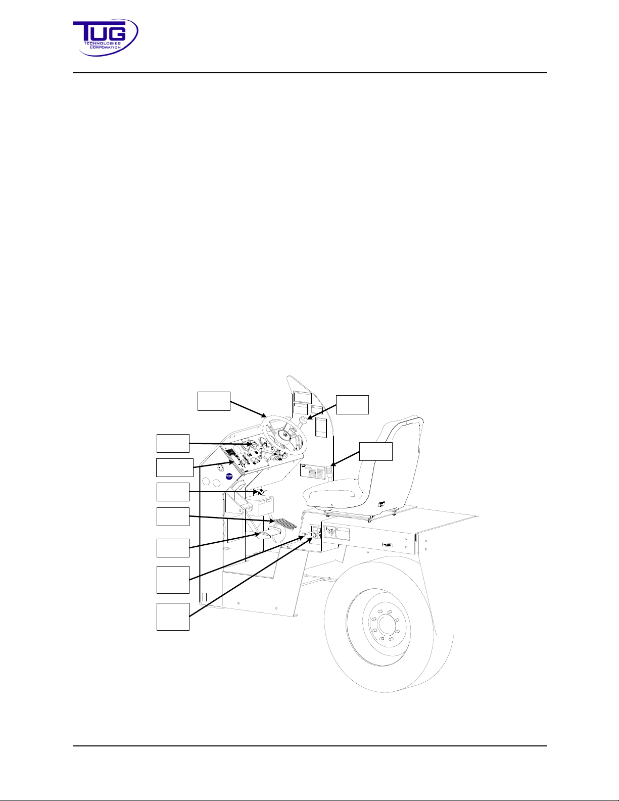
Mobile Belt Loader Model 660 Operation
T
-
S
2
W
A
R
N
IN
G
H
y
d
r
a
u
l
i
c
f
l
u
i
d
s
u
n
d
e
r
p
r
e
s
s
u
r
e
c
a
n
c
a
u
s
e
i
n
j
u
r
y
.
K
e
e
p
h
a
n
d
s
a
w
a
y
f
r
o
m
l
e
a
k
s
.
H
y
d
r
a
u
l
i
c
f
l
u
i
d
u
n
d
e
r
p
r
e
s
s
u
r
e
c
a
n
p
e
n
e
t
r
a
t
e
s
k
i
n
t
h
r
o
u
g
h
g
l
o
v
e
s
o
r
c
l
o
t
h
i
n
g
.
D
o
n
o
t
a
t
t
e
m
p
t
t
o
l
o
o
k
f
o
r
l
e
a
k
s
w
i
t
h
h
a
n
d
s
.
M
J
-
1
E
.
.
.
.
.
.
.
.
.
.
.
.
.
.
.
.
.
.
.
.
.
.
.
.
.
.
.
.
.
.
.
.
.
.
.
.
.
.
.
.
.
.
.
.
.
.
.
.
.
.
.
.
.
.
.
.
.
.
.
.
.
.
.
.
.
.
.
.
.
.
.
.
.
.
.
.
.
.
.
.
.
.
.
.
.
.
.
.
.
.
.
.
.
.
.
.
.
.
.
.
.
.
.
.
.
.
.
.
.
.
.
.
.
.
.
.
.
.
.
.
.
.
.
.
.
.
.
.
.
.
.
.
.
.
.
.
.
.
.
.
.
.
.
.
.
.
.
.
.
.
.
.
.
.
.
.
.
.
.
.
.
.
.
.
.
.
.
.
.
.
.
.
.
.
.
.
.
.
.
.
.
.
.
.
.
.
.
.
.
.
.
.
.
.
.
.
.
.
.
.
.
.
.
.
.
.
.
.
.
.
.
.
.
.
.
.
.
.
.
.
.
.
.
.
.
.
.
.
.
.
.
.
.
.
.
.
.
.
.
.
.
.
.
.
.
.
.
.
.
.
.
.
.
.
.
.
.
.
.
.
.
.
.
.
.
.
.
.
.
.
.
.
.
.
.
.
.
.
.
.
.
.
.
.
.
.
.
.
.
.
.
.
.
.
.
.
.
.
.
.
.
.
.
.
.
.
.
.
.
.
.
.
.
.
.
.
.
.
.
.
.
.
.
.
.
.
.
.
.
.
.
.
.
.
.
.
.
.
.
.
.
.
.
.
.
.
.
.
.
.
.
.
.
.
.
.
.
.
.
.
.
.
.
.
.
.
.
.
.
.
.
.
.
.
.
.
.
.
.
.
.
.
.
.
.
.
.
.
.
.
.
.
.
.
.
.
.
.
.
.
.
.
.
.
.
.
.
.
.
.
.
.
..
.
.
.
.
.
.
.
.
.
.
.
.
.
.
.
.
.
.
.
.
.
.
.
.
.
.
.
.
.
.
.
.
.
.
.
.
.
.
.
P
A
R
T
N
O
.
:
T
6
-
9
0
1
1
-
4
8
5
.
.
.
.
.
.
.
!
A
L
W
A
Y
S
B
R
I
N
G
T
H
E
U
N
I
T
T
O
A
C
O
M
P
L
E
T
E
S
T
O
P
,
P
L
A
C
E
T
H
E
D
I
R
E
C
T
I
O
N
A
L
C
O
N
T
R
O
L
I
N
N
E
U
T
R
A
L
,
A
N
D
A
P
P
L
Y
T
H
E
P
A
R
K
B
R
A
K
E
B
E
F
O
R
E
D
I
S
M
O
U
N
T
I
N
G
!
A
L
W
A
Y
S
S
T
O
P
T
R
A
C
T
O
R
W
I
T
H
S
E
R
V
I
C
E
(
F
O
O
T
)
B
R
A
K
E
!
N
E
V
E
R
S
T
O
P
T
R
A
C
T
O
R
W
I
T
H
P
A
R
K
I
N
G
(
H
A
N
D
)
B
R
A
K
E
!
T
Y
-
5
9
A
L
L
O
P
E
R
A
T
O
R
S
U
S
I
N
G
T
H
I
S
E
Q
U
I
P
M
E
N
T
S
H
A
L
L
:
1
.
B
E
P
R
O
P
E
R
L
Y
T
R
A
I
N
E
D
.
2
.
C
O
M
P
L
Y
W
I
T
H
O
P
E
R
A
T
I
O
N
S
M
A
N
U
A
L
.
.
3
.
A
D
H
E
R
E
T
O
A
L
L
S
A
F
E
T
Y
R
E
Q
U
I
R
E
M
E
N
T
S
.
C
A
U
T
I
O
N
T
4
3
0
T
-
Y
3
4
C
A
U
T
I
ON
P
U
T
T
R
A
N
S
M
I
S
S
I
O
N
I
N
N
E
U
T
R
A
L
A
N
D
S
E
T
P
A
R
K
I
N
G
B
R
A
K
E
B
E
F
O
R
E
O
P
E
R
A
T
I
N
G
C
O
N
V
E
Y
O
R
O
R
S
E
R
V
I
C
I
N
G
A
I
R
C
R
A
F
T
U
L
T
R
A
L
O
W
-
S
U
L
F
U
R
D
I
E
S
E
L
F
U
E
L
O
N
L
Y
T
-
A
5
6
D
D
O
W
N
U
P
C
O
N
V
E
Y
O
R
C
O
N
T
R
O
L
T
-
A
1
5
F
R
O
N
T
R
E
A
R
.
.
.
.
.
.
.
.
.
.
.
.
.
.
.
.
.
.
.
.
.
.
.
.
.
.
.
.
.
.
.
.
.
.
.
.
.
.
.
.
.
.
.
.
.
.
.
.
.
.
.
.
.
.
.
.
.
.
.
.
.
.
.
.
.
.
.
.
.
.
.
.
.
.
.
.
.
.
.
.
.
.
.
.
.
.
.
.
.
.
.
.
.
.
.
.
.
.
.
.
.
.
.
.
.
.
.
.
.
.
.
.
.
.
.
.
.
.
.
.
.
.
.
.
.
.
.
.
.
.
.
.
.
.
.
.
.
.
.
.
.
.
.
.
.
.
.
.
.
.
.
.
.
.
.
.
.
.
.
.
.
.
.
.
.
.
.
.
.
.
.
.
.
.
.
.
.
.
.
.
.
.
.
.
.
.
.
.
.
.
.
.
.
.
.
.
.
.
.
.
.
.
.
.
.
.
.
.
.
.
.
.
.
.
.
.
.
.
.
.
.
.
.
.
.
.
.
.
.
.
.
.
.
.
.
.
.
.
.
.
.
.
.
.
.
.
.
.
.
.
.
.
.
.
.
.
.
.
.
.
.
.
.
.
.
.
.
.
.
.
.
.
.
.
.
.
.
.
.
.
.
.
.
.
.
.
.
.
.
.
.
.
.
.
.
.
.
.
.
.
.
.
.
.
.
.
.
.
.
.
.
.
.
.
.
.
.
.
.
.
.
.
.
.
.
.
.
.
.
.
.
.
.
.
.
.
.
.
.
.
.
.
.
.
.
.
.
.
.
.
.
.
.
.
.
.
.
.
.
.
.
.
.
.
.
.
.
.
.
.
.
.
.
.
.
.
.
.
B
E
L
T
L
O
A
D
E
R
O
P
E
R
A
T
O
R
'
S
D
A
I
L
Y
C
H
E
C
K
L
I
S
T
B
u
m
p
e
r
B
e
l
t
C
o
n
v
e
y
e
r
E
l
e
c
t
r
i
c
C
o
n
t
r
o
l
B
o
x
E
m
e
r
g
e
n
c
y
S
t
o
p
(
E
-
S
t
o
p
)
b
u
t
t
o
n
(
s
)
H
o
r
n
D
r
i
v
e
r
c
o
m
p
a
r
t
m
e
n
t
c
o
m
p
o
n
e
n
t
s
:
p
e
d
a
l
s
,
d
a
s
h
p
a
n
e
l
,
s
e
a
t
b
e
l
t
.
P
a
r
k
i
n
g
b
r
a
k
e
A
n
t
i
s
l
i
p
c
o
a
t
i
n
g
H
e
a
d
l
i
g
h
t
s
F
u
e
l
/
S
t
a
t
e
o
f
c
h
a
r
g
e
(
a
s
a
p
p
l
i
c
a
b
l
e
)
C
h
o
c
k
s
(
a
s
a
p
p
l
i
c
a
b
l
e
)
B
a
t
t
e
r
y
h
o
u
s
i
n
g
S
a
f
e
t
y
r
a
i
l
S
p
o
t
l
i
g
h
t
(
i
f
a
p
p
l
i
c
a
b
l
e
)
T
i
r
e
s
U
n
d
e
r
t
h
e
v
e
h
i
c
l
e
f
o
r
l
e
a
k
s
W
h
e
n
a
n
y
p
i
e
c
e
o
f
g
r
o
u
n
d
e
q
u
i
p
m
e
n
t
b
e
c
o
m
e
s
i
n
o
p
e
r
a
b
l
e
:
1
.
R
e
m
o
v
e
t
h
e
e
q
u
i
p
m
e
n
t
f
r
o
m
s
e
r
v
i
c
e
a
n
d
d
o
n
o
t
u
s
e
u
n
t
i
l
t
h
e
r
e
p
a
i
r
s
h
a
v
e
b
e
e
n
m
a
d
e
.
2
.
N
o
t
i
f
y
a
r
a
m
p
s
u
p
e
r
v
i
s
o
r
.
T
W
4
0
T
B
8
T-B7
A
R
A
V
N
O
R
M
A
L
T
6
-
4
7
0
0
-
0
7
6
C
O
D
E
R
E
A
D
6
6
0
-
1
-
2
9
8
2
S
W
I
T
C
H
Steering
Wheel
Turn
Signal
Foot
Throttle
Brake
Pedal
Shifter
Front
Cylinder
Control
Rear
Cylinder
Control
Parking
Brake
Code
Switch
Instrument
Panel
Operation Manual
1.4.10Conveyor
The conveyor is fabricated from structural shapes and formed steel, and is attached to the chassis through front and rear lifting frames.
The front cylinder, supporting the front lifting frame, raises
the conveyor to 170 in. (431.8 cm) on
the Model 660.
The conveyor frame is 34 in. (86.36 cm) wide on 660 and
31.5 in. (80.009 cm) on 663. The conveyor belt is 24 in. (60.96 cm) wide on all models and is supported by 2 in. (5.08 cm) diameter
rollers a
nd is hydraulic motor-driven through a roller chain reduction. The front roller is mounted
in a flange block with a screw-adjustable take-up that allows 6 in. (15.24 cm) of adjustment.
Crowder rollers under the support rollers direct the return side of the belt into areas where
required clearances around fixed components is maintained. An inverted angle iron track on the
lower forward section of the conveyor maintains lateral stability through V-shaped rollers
mounted to the front lift frame.
r
Operator stations for controlling the conveyo
belt are located on the left side at each end of the
conveyor. Alternative positions are available as options.
1.4.11Operator’sCompartment
The operator's compartment contains all the required controls to drive the vehicle and to control
the lifting and lowering of the conveyor.
FigureOperation-1-1:Operator’sCompartment
Operation - 1 - 6 CD397-Oper
Page 69

Operation Mobile Belt Loader Model 660
Operation Manual
Engine controls are mounted in the operator’s compartment instrument panel and include hour
meter, ignition switch, and light switches.
1.4.12ElectricalSystem
Electrical power is supplied by an alternator, belt-driven, mounted on the side of the engine. The
system is a 12-volt, direct current system with negative ground.
All operating circuits are wired through the ignition swit
ch and are protected by circuit breakers.
1.4.13HydraulicSystem
1.4.13.1GeneralHydraulicsOperation
The hydraulic schematic (see the Maintenance Manual) represents an open center system that
supplies power to raise and lower the conveyor and to drive the conveyor belt.
Hydraulic power is supplied by a hydraulic pump,
The pump supplies 9 gpm (34.08 lpm) at 1500 rpm to raise and lower the conveyor and to drive
the conveyor belt.
Both lift cylinders are locked in any position by hold
a counterbalance and cushion valve in the circuit.
All hydraulic hose connections are Ga
reinforcing wire inside the hose. This is more reliable than the grip on the rubber of the hose.
Mega Crimp connections are plated to resist damage from corrosion. The Mega Crimp connections are rated at 3000 psi (US) (20.68 MPa or 204.14 atm) working pre
are Gates brand Mega 3000 rated for 3250 psi (22.41 MPa or 221.15 atm) working pressure. All
pipes are constructed from Benteler hydraulic piping rated for 3000 PSI (20.68 MPa 204.14 atm)
working pressure.
tes brand Mega Crimp. Mega Crimp connectors join the
belt- or gear-driven, mounted on the engine.
ing valves.The orbital motor has incorporated
ssure. All hydraulic hoses
Hydraulic fluid is drawn from the hydraulic oil reservoir to the hydraulic pu
(22.71 l) to ten gals (37.85 l) per minute into a pipe manifold. From the pump, fluid is directed to a
pressure-compensated flow divider valve in the valve manifold, located under the driver’s seat.
The pressure-compensated flow divider valve separates the hydraulic system into a steering and
braking section and a lift cylinder and conveyor motor section.
mp at a rate of six gals
1.4.13.2SteerandBraking
The pressure-compensated flow divider valve provides a constant 2 gpm (7.57 lpm) of oil flow to
the Steering / Braking portion of the hydraulic system. Hydraulic fluid pressure for the steering
and braking section is limited by a pressure relief valve, set at 1000 psi (6.9 MPa or 68.05 atm),
in the hydraulic manifold. Hydraulic oil then flows to the hydraulic brake system assist valve via
port, then to the hydraulic steering motor.
Fluid from the hydraulic brake system assist valve and the hydra
manifold. This fluid then exits the manifold. Fluid passes through the return line hydraulic filter
before returning to the hydraulic oil reservoir.
When the brake pedal is depressed, pressurized hydraulic f
tem assist valve and exerts pressure on a spring
CD397-Oper Operation - 1 - 7
loaded check valve, closing the hydraulic fluid
ulic steering motor return to the
luid enters the hydraulic brake sys-
Page 70

Mobile Belt Loader Model 660 Operation
Operation Manual
line that returns oil to the hydraulic oil reservoir through ports on the valve manifold assembly.
When the brake pedal is released, pressure is reduced and the spring loaded check valve opens,
allowing hydraulic fluid to return to the hydraulic oil reservoir through ports on the valve manifold
assembly and the return line hydraulic filter.
Hydraulic fluid also flows to the hydraulic steering motor which controls the hydraulic steer cylinder.
When the steering wheel position is altered,
pressurized hydraulic fluid enters the steering valve
through port. Depending on the direction of steering input, flow is diverted through ports to the
appropriate side of the steer cylinder through hydraulic lines. Flow out of the steering cylinder
and excess flow coming in through port returns to the manifold via ports. This fluid then exits the
manifold via port. Fluid passes through the return line hydraulic filter before returning to the
hydraulic oil reservoir.
1.4.13.3LiftCylindersandConveyorMotor
Pressurized hydraulic oil not being used by the steering/braking systems bypasses the flow
divider valve and then flows into an adjustable relief valve that allows hydraulic fluid to return to
the hydraulic oil reservoir through port on the valve manifold assembly and the return line
hydraulic filter.
When the two manual levers for the front and back lift cylinders or the motor driven directional
valve are
(10.34 MPa or 102.07 atm).
The adjustable relief valve, located downstream of th
sure of 900 psi (6.2 MPa or 62.24 atm), keeping the front cylinder from applying excessive downwards force.
The two manual levers control the front and rear lift cylinders and the motor driven directional
valve co
activated, the upstream adjustable relief valve closes at the set pressure of 1500 psi
e front lift cylinder, closes at the set pres-
ntrols the conveyor hydraulic motor / CBV assembly.
When a manual lever is actuated, the lever mechanically shifts the spool valve
position, porting
fluid to that side of the lift cylinder to be pressurized. Spool Valve movement also opens a channel for the non-pressurized portion of the lift cylinder
piston to allow unpressurized oil to return to
the hydraulic oil reservoir through port on the valve manifold assembly and the return line
hydraulic filter.
Likewise, when the conveyor motor control valve is actuated
noid shifts the spool valve position, porting fluid to
the forward or reverse side of the conveyor
in either direction, its electric sole-
motor/CBV assembly. Spool valve movement also opens a channel for the non-pressurized portion of the conveyor motor/CBV assembly to allow unp
ressurized oil to return to the hydraulic oil
reservoir through port on the valve manifold assembly and the return line hydraulic filter.
With the manual control levers in their neutral state, the front and rear cylinders are locked in the
current p
Operation - 1 - 8 CD397-Oper
osition by load holding valves, located on their respective cylinders.
Page 71

Operation Mobile Belt Loader Model 660
Operation Manual
DCEmergencyPump
In the case of Main Hydraulic Pump failure, the DC-operated Emergency Pump is available for
the temporary activation of the Hydraulic Lift Cylinders and the Conveyor Motor. The emergency
pump cannot operate the steering and braking system.
The 660 belt loader is equipped with an electrically opera
ted emergency hydraulic pump to allow
short term operation of the hydraulic system for raising or lowering the conveyor, in the event of
an engine failure. The hydraulic pump relies on the 12 volt starter battery for energy.
CAUTION: The emergency hydraulic pump should only be operated when
the regular propulsion engine is OFF or NOT operating.
The purpose of the emergency hydraulic pump is to enable lowering of the conveyor into its normal down position, or to retrieve luggage that may be on the belt at the time of engine failure. It
may a
lso be used to gain access to the engine compartment if the conveyor is in the down posi-
tion.
CAUTION: Use the safety props to support the conveyor at all times when
performing maintenance under the conveyor.
The emergency hydraulic pump is not to be used to load or u
nload luggage to or from the hold of
the plane at any time.
The emergency hydraulic pump is activated by a butt
on on the instrument panel that is labeled
“Emergency Hydraulic Pump”. Pressing the button down activates the pump, releasing the button
stops the operation of the pump, thus all the time hydraulic power is required during emergency
conditions the button should be depressed.
There is an electrical safety circuit for the emergency pump, located next to the
NOTE:
hydraulic tank, it will trip if the current drawn from the battery to operate the emergency pump exceeds preset limits. It may be reset by pressing down the red button marked 105.
The Emergency Hydraulic Pump should be tested daily before equipment use, any concerns
ab
out its operation should be reported to the crew supervisor.
CD397-Oper Operation - 1 - 9
Page 72

Mobile Belt Loader Model 660 Operation
Operation Manual
THIS PAGE INTENTIONALLY BLANK
Operation - 1 - 10 CD397-Oper
Page 73

Operation Mobile Belt Loader Model 660
Operation Manual
Section2:OperationalProcedures
2.1InstrumentPanelControlsandIndicators
2.1.1Ford2.5L
Table Operation-2-1, “Instrument Panel Description - Ford 2.5L,” lists the controls, indicators,
and equipment found on the instrument panel for the 660 belt loader with the Ford 2.5L gasoline
engine, and explains the specific function of each. Reference Table Operation - 2 - 1, “Instrument
Panel - Ford 2.5L,” for the location of the items listed.
2.1.2Deutz2.9LTier4F
“Figure Operation - 2 - 2” lists the controls, indicators, and equipment found on the instrument
panel for the 660 Belt loader with the Deutz Tier 4F engine, and explains the specific function of
each. Reference Table Operation-2-2, “Instrument Panel Description - Deutz 2.9L,” for a description of the items shown.
CD397-Oper Operation - 2 - 11
Page 74
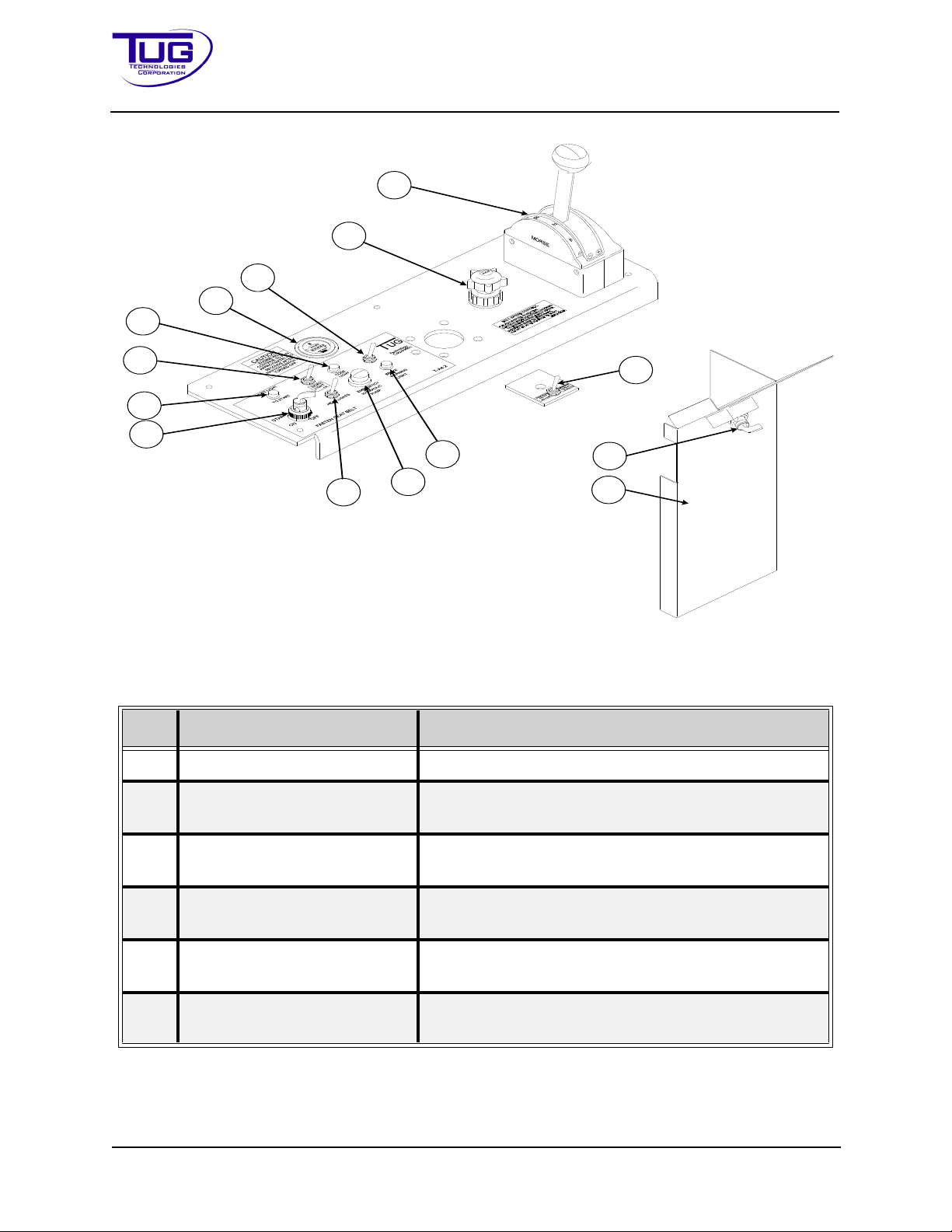
Mobile Belt Loader Model 660 Operation
6
7
8
5
2
3
4
1
12
11
10
9
13
14
Operation Manual
FigureOperation-2-1InstrumentPanel-Ford2.5L
TableOperation-2-1InstrumentPanelDescription-Ford2.5L
No. Name Description
1 Ignition Switch Turn this switch to start or turn off the engine.
2 Warning Light (Green) This light will not illuminate if an e-stop on the vehi-
3 Spot Light Switch (Optional) This switch turns the spotlight on. Press down for
4 Warning Code Light (Red) This light illuminates briefly during engine start and
5 Hour Meter This gauge displays the number of operation hours
6 Fuel Select Toggle Switch
(Optional)
cle is activated.
off, or up for on.
when an engine fault occurs.
on the tractor.
This switch controls the dual fuel operation. Select
LP or gasoline as the engine fuel source.
Operation - 2 - 12 CD397-Oper
Page 75

Operation Mobile Belt Loader Model 660
Operation Manual
Tabl e Operation-2-1InstrumentPanelDescription-Ford2.5L(Continued)
No. Name Description
7 Conveyor Hand Throttle This knob controls the engine speed only while the
unit is in neutral and the parking brake is applied.
Turn the knob counterclockwise and the engine will
speed up. Depress the hand throttle knob and the
engine will return to idle.
8 Morse Shifter This is the main drive control for forward or reverse
direction. The shifter is labeled: F=Forward,
R=Reverse, and N=Neutral.
9 Code Toggle Switch Press this switch to read fault codes via the diagnos-
tic lamp.
10 Brake Warning Light (Red) This light illuminates if the brake system pressure
falls below a preset level.
11 Emergency Steering Switch This switch activates the emergency steering pump.
Press and hold the switch to start the pump, or
release the switch to stop the pump. The emergency
steering pump activates only if hydraulic pressure is
low.
12 Head Light Switch This switch turns the tractor’s headlights on or off.
Pressing down turns lights off and pressing up turns
lights on.
13 Ignition Switch (Optional
This switch starts or turns off the tractor's engine.
Location)
14 Left Front Headlight Cover This cover is installed below the dash and conceals
the tractor's wiring harnesses.
CD397-Oper Operation - 2 - 13
Page 76
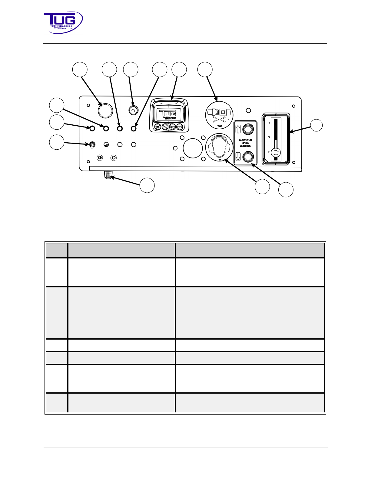
Mobile Belt Loader Model 660 Operation
4
8 10
3
12 13
2
5
6
7
9
11
1
Operation Manual
FigureOperation-2-2InstrumentPanel-Deutz2.9L
Tabl e Operation-2-2InstrumentPanelDescription-Deutz2.9L
No. Name Description
1 Shifter This is the main drive control for forward or
reverse direction. The shifter is labeled:
F=Foward, R=Reverse, and N=Neutral.
2 Converter Speed Control These buttons control the engine speed only
while the belt loader is in neutral and the parking
brake is applied. Press the button closest to the
UP arrow: engine RPMs and belt speed
increases. Press the DOWN arrow: engine
RPMs and belt speed decreases.
3 Hearing Protection Decal Always wear hearing protection.
4 Ignition Switch Turn this switch to start or turn off the engine.
5 Headlight Switch This switch turns the headlights on or off. Flip
switch up to turn lights ON and down to turn
lights OFF.
6 Warning Light This warning light illuminates when headlights
Operation - 2 - 14 CD397-Oper
are on.
Page 77

Operation Mobile Belt Loader Model 660
Operation Manual
Table Operation-2-2InstrumentPanelDescription-Deutz2.9L(Continued)
No. Name Description
7 Deutz Cold Start Wait Light When the ignition switch is turned on, this light
illuminates. When the light goes out, it shows
that the glow plugs are heated and the vehicle
can be started.
8 Emergency Stop Switch Press the switch down to shut the engine off.
The switch must be rotated clockwise and pulled
out to allow the engine to restart.
9 Warning Light Optional warning light.
10 Emergency Lift Pump Switch Press this button for emergency hydraulic pres-
sure to the conveyor.
11 Warning Light Optional warning light.
12 Murphy CAN Display Information displayed is provided by the ECM
and may include:
• Engine Speed
• Engine Torque
• Coolant Temperature
• Intake Air Temperature
• Exhaust Gas Temperature
• Oil Pressure
• Coolant Pressure
• Fuel Level
• Battery Voltage
• Total Operating Hours
• Error Messages
13 Fasten Seat Belt Decal Always fasten seat belt before operating the
Mobile Belt Loader Model 660.
2.1.3ManeuveringControls
1. Steering Wheel
2. Brake Pedal
3. Foot Throttle
4. Turn Signal
5. Shifter
CD397-Oper Operation - 2 - 15
Page 78
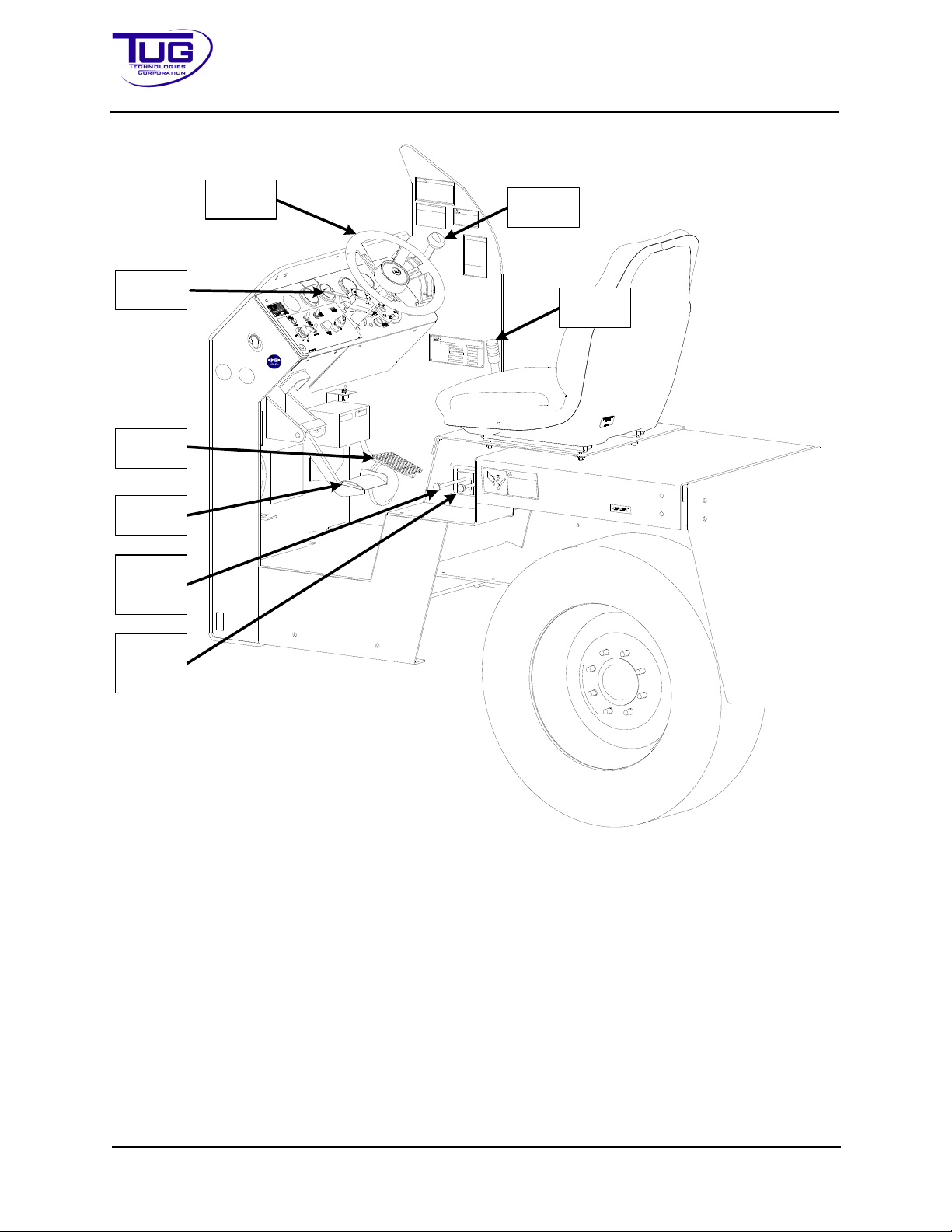
Mobile Belt Loader Model 660 Operation
T
-
S
2
W
A
R
N
I
N
G
H
y
d
r
a
u
l
i
c
f
l
u
i
d
s
u
n
d
e
r
p
r
e
s
s
u
r
e
c
a
n
c
a
u
s
e
i
n
j
u
r
y
.
K
e
e
p
h
a
n
d
s
a
w
a
y
f
r
o
m
l
e
a
k
s
.
H
y
d
r
a
u
l
i
c
f
l
u
i
d
u
n
d
e
r
p
r
e
s
s
u
r
e
c
a
n
p
e
n
e
t
r
a
t
e
s
k
i
n
t
h
r
o
u
g
h
g
l
o
v
e
s
o
r
c
l
o
t
h
i
n
g
.
D
o
n
o
t
a
t
t
e
m
p
t
t
o
l
o
o
k
f
o
r
l
e
a
k
s
w
i
t
h
h
a
n
d
s
.
M
J
-
1
E
P
A
R
T
N
O
.
:
T
6
-
9
0
1
1
-
4
8
5
!
A
L
W
A
Y
S
B
R
I
N
G
T
H
E
U
N
I
T
T
O
A
C
O
M
P
L
E
T
E
S
T
O
P
,
P
L
A
C
E
T
H
E
D
I
R
E
C
T
I
O
N
A
L
C
O
N
T
R
O
L
I
N
N
E
U
T
R
A
L
,
A
N
D
A
P
P
L
Y
T
H
E
P
A
R
K
B
R
A
K
E
B
E
F
O
R
E
D
I
S
M
O
U
N
T
I
N
G
!
A
L
W
A
Y
S
S
T
O
P
T
R
A
C
T
O
R
W
I
T
H
S
E
R
V
I
C
E
(
F
O
O
T
)
B
R
A
K
E
!
N
E
V
E
R
S
T
O
P
T
R
A
C
T
O
R
W
I
T
H
P
A
R
K
I
N
G
(
H
A
N
D
)
B
R
A
K
E
!
T
Y
-
5
9
A
L
L
O
P
E
R
A
T
O
R
S
U
S
I
N
G
T
H
I
S
E
Q
U
I
P
M
E
N
T
S
H
A
L
L
:
1
.
B
E
P
R
O
P
E
R
L
Y
T
R
A
I
N
E
D
.
2
.
C
O
M
P
L
Y
W
I
T
H
O
P
E
R
A
T
I
O
N
S
M
A
N
U
A
L
.
.
3
.
A
D
H
E
R
E
T
O
A
L
L
S
A
F
E
T
Y
R
E
Q
U
I
R
E
M
E
N
T
S
.
C
A
U
T
I
O
N
T
4
3
0
T
-
Y
3
4
C
A
U
T
I
O
N
P
U
T
T
R
A
N
S
M
I
S
S
I
O
N
I
N
N
E
U
T
R
A
L
A
N
D
S
E
T
P
A
R
K
I
N
G
B
R
A
K
E
B
E
F
O
R
E
O
P
E
R
A
T
I
N
G
C
O
N
V
E
Y
O
R
O
R
S
E
R
V
I
C
I
N
G
A
I
R
C
R
A
F
T
U
L
T
R
A
L
O
W
-
S
U
L
F
U
R
D
I
E
S
E
L
F
U
E
L
O
N
L
Y
T
-
A
5
6
D
D
O
W
N
U
P
C
O
N
V
E
Y
O
R
C
O
N
T
R
O
L
T
A
1
5
F
R
O
N
T
R
E
A
R
B
E
L
T
L
O
A
D
E
R
O
P
E
R
A
T
O
R
'
S
D
A
I
L
Y
C
H
E
C
K
L
I
S
T
B
u
m
p
e
r
B
e
l
t
C
o
n
v
e
y
e
r
E
l
e
c
t
r
i
c
C
o
n
t
r
o
l
B
o
x
E
m
e
r
g
e
n
c
y
S
t
o
p
(
E
-
S
t
o
p
)
b
u
t
t
o
n
(
s
)
H
o
r
n
D
r
i
v
e
r
c
o
m
p
a
r
t
m
e
n
t
c
o
m
p
o
n
e
n
t
s
:
p
e
d
a
l
s
,
d
a
s
h
p
a
n
e
l
,
s
e
a
t
b
e
l
t
.
P
a
r
k
i
n
g
b
r
a
k
e
A
n
t
i
s
l
i
p
c
o
a
t
i
n
g
H
e
a
d
l
i
g
h
t
s
F
u
e
l
/
S
t
a
t
e
o
f
c
h
a
r
g
e
(
a
s
a
p
p
l
i
c
a
b
l
e
)
C
h
o
c
k
s
(
a
s
a
p
p
l
i
c
a
b
l
e
)
B
a
t
t
e
r
y
h
o
u
s
i
n
g
S
a
f
e
t
y
r
a
i
l
S
p
o
t
lig
h
t
(
i
f
a
p
p
l
i
c
a
b
l
e
)
T
i
r
e
s
U
n
d
e
r
t
h
e
v
e
h
i
c
l
e
f
o
r
l
e
a
k
s
W
h
e
n
a
n
y
p
i
e
c
e
o
f
g
r
o
u
n
d
e
q
u
i
p
m
e
n
t
b
e
c
o
m
e
s
i
n
o
p
e
r
a
b
l
e
:
1
.
R
e
m
o
v
e
t
h
e
e
q
u
i
p
m
e
n
t
f
r
o
m
s
e
r
v
i
c
e
a
n
d
d
o
n
o
t
u
s
e
u
n
t
i
l
t
h
e
r
e
p
a
i
r
s
h
a
v
e
b
e
e
n
m
a
d
e
.
2
.
N
o
t
i
f
y
a
r
a
m
p
s
u
p
e
r
v
i
s
o
r
.
T
W
4
0
T
B
8
T-B7
A
R
A
V
N
O
R
M
A
L
T
6
-
4
7
0
0
-
0
7
6
C
O
D
E
R
E
A
D
6
6
0
-
1
-
2
9
8
2
S
W
I
T
C
H
Steering
Wheel
Turn
Signal
Foot
Throttle
Brake
Pedal
Shifter
Front
Cylinder
Control
Rear
Cylinder
Control
Parking
Brake
Operation Manual
FigureOperation-2-3ManeuveringandConveyorControls
2.1.4ConveyorControls
Conveyor height controls in the operator’s compartment (located below driver’s seat) are limited
to:
1. Front Cylinder: Raises / lowers front of conveyor. See Figure Operation - 2 - 3
2. Rear cylinder: Raises / lowers back of conveyor. See Figure Operation - 2 - 3
Operation - 2 - 16 CD397-Oper
Page 79
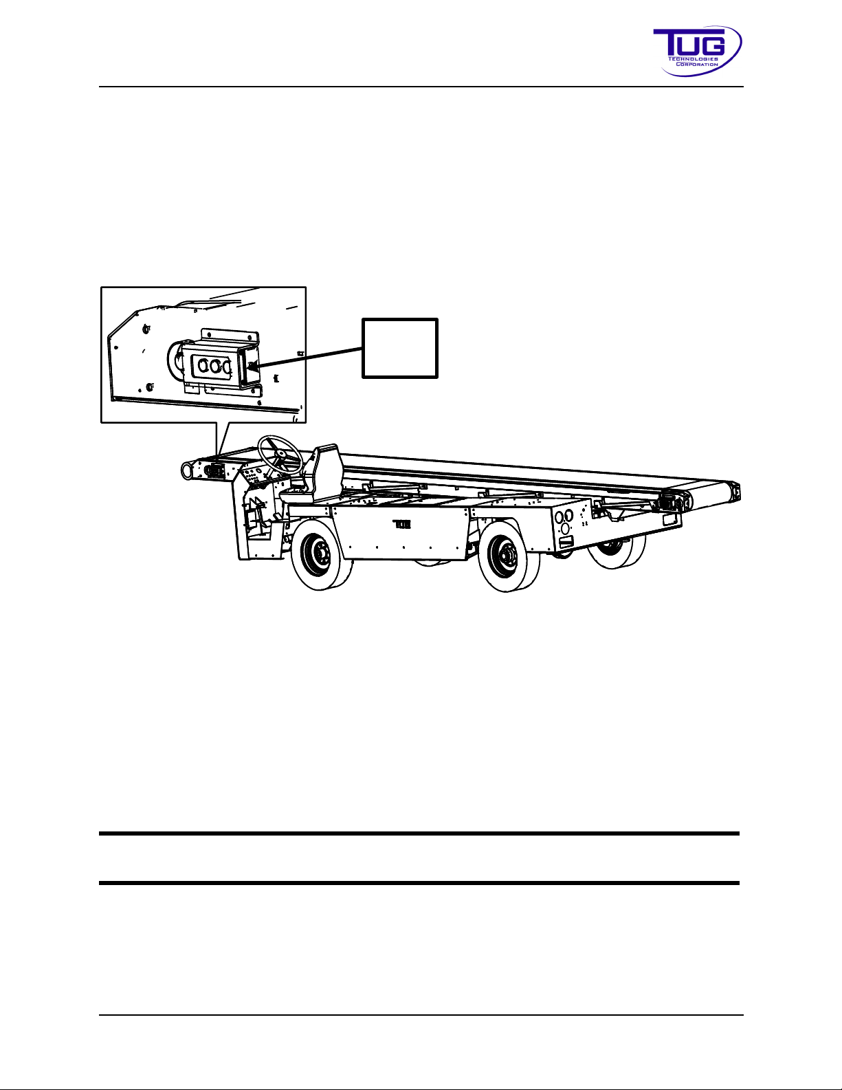
Operation Mobile Belt Loader Model 660
Conveyor
Belt Drive
Controls
Operation Manual
Electrical belt drive controls may be located at any combination of the conveyor's four corners.
On the Ford 2.5L, the conveyor hand throttle controls engine speed while in neutral. Turn the
knob counterclockwise and the engine will speed up. Depress the hand throttle knob and the
engine will return to idle.
On the Duetz, the conveyor speed control is located on the instrument panel. Push buttons control the conveyor speed (see callout #2 on Figure Operation - 2 - 2), while in neutral. Push the
button with the arrow pointing up to increase engine speed or push the button with the arrow
pointing down to return to idle.
FigureOperation-2-4ConveyorControls
Control relays for the electrical conveyor belt drive solenoid control valves are located on the
conveyor frame.
2.1.5ElectricalSupply
The main electrical supply panel is located
• Ford: below the instrument panel
• Deutz: in the battery compartment.
NOTE:
See the electrical schematics in the Maintenance Manual for description of electrical components.
2.1.6PreliminaryChecks
Procedures for preliminary checks before maneuvering the vehicle to an aircraft shall include (but
may not be limited to) the following items:
CD397-Oper Operation - 2 - 17
Page 80

1. Fuel Level
2. Tire Inflation
3. Engine Oil Level
4. Transmission Oil Level
5. Seatbelt Serviceability
6. Service Brake Effectiveness
7. Parking Brake Effectiveness
8. Vehicle Drive Forward
9. Vehicle Drive Reverse
Mobile Belt Loader Model 660 Operation
Operation Manual
10. Check the hydraulic fluid level with the conveyor down
11. Conveyor Belt Drives in Forward direction
12. Conveyor Belt Drives in Reverse direction
13. Front Cylinder Extension: Raises front of conveyor
14. Front Cylinder Retraction: Lowers front of conveyor
15. Rear Cylinder Extension: Raises back of conveyor
16. Rear Cylinder Retraction: Lowers back of conveyor
17. Verify all "E" Stops function correctly
2.1.7ManeuveringProcedures
Procedures for maneuvering the vehicle to an aircraft are outlined below:
WARNING: OBSERVE ALL SAFETY PRECAUTIONS DISCUSSED IN THE
SAFETY SECTION OF THIS MANUAL.
2.1.7.1EngineStartProcedure(Gas)
1. Apply parking brake.
2. Move transmission selector to Neutral. (Starter motor will not activate unless selector is in
Neutral).
Operation - 2 - 18 CD397-Oper
Page 81

Operation Mobile Belt Loader Model 660
Operation Manual
3. Move ignition switch to “Start”.
4. Allow ignition switch to return to “On” upon engine start.
NOTE:
Switch must be returned to “Off” (reset) before it can be moved to start again.
2.1.7.2EngineStart(Diesel)
1. Apply parking brake.
2. Move transmission selector to Neutral. (Starter motor will not activate unless selector is in
Neutral).
3. Move ignition switch to “Start”.
4. Wait for “Wait-to-Start” light to go out.
5. Allow ignition switch to return to “On” upon engine start.
NOTE:
Switch must be returned to “Off” (reset) before it can be moved to start again.
2.1.7.3Releaseparkingbrake.
The parking brake is a cable-actuated type attached to the brake shoes in the rear axle.
NOTE:
The parking brake is located to the right of the driver’s seat in the driver’s compartment. See Figure Operation - 2 - 3.
1. To apply parking brake, pull up.
2. To release parking brake, push down.
2.1.7.4TransmissionDrive(FWD/REV)Selection.
A Morse control is connected to the transmission shift lever through a flexible push/pull cable.
To select a vehicle drive direction in a USA configured belt loader:
1. Move transmission drive selector lever up (toward instrument panel) to select reverse
drive direction.
2. Move transmission drive selector lever down (toward driver’s seat) to select forward drive
direction.
3. Neutral is located midway between forward and reverse and is indicated by a positive
stop notch into which the spring loaded lever will fall when shifting.
CD397-Oper Operation - 2 - 19
Page 82

Mobile Belt Loader Model 660 Operation
Operation Manual
4. Select transmission drive (FWD/REV)
To select a vehicle drive direction in a CE configured belt loader:
1. Move transmission drive selector lever up (toward instrument panel) to select forward
drive direction.
2. Move transmission drive selector lever down (toward driver’s seat) to select reverse drive
direction.
3. Neutral is located midway between forward and reverse and is indicated by a positive
stop notch into which the spring loaded lever will fall when shifting.
4. Select transmission drive (FWD/REV)..
This transmission is equipped with Abuse Protection Valve Body. To shift into
Reverse (R) or Drive (D), all three of the following conditions must be met:
1. Throttle position must be less than 25%.
2. Engine RPM must be less than 1500 RPM.
NOTE:
3. Vehicle speed must be 0 MPH.
If any of the above conditions are not met, the transmission will be placed into a
neutral state until all three conditions are met. This neutral state may slightly drag
the forward or reverse clutch, moving the vehicle very slowly and give the impression that the transmission is slipping. To fully engage the desired gear, simply come
to a complete stop with the engine at idle.
2.1.7.5Depressfootthrottle.
The foot throttle is a conventional automobile accelerator connected to the ECM by electrical
connection.
• To increase speed, depress foot throttle.
• To decrease speed, release foot throttle.
2.1.7.6Maneuvervehiclewithsteeringwheel.
The steering system is a hydrostatic type powered from the belt-driven hydraulic pump.
• To turn left, rotate the steering wheel counterclockwise.
• To turn right, rotate the steering wheel clockwise.
Operation - 2 - 20 CD397-Oper
Page 83
Operation Mobile Belt Loader Model 660
Operation Manual
2.1.7.7Maneuveringthebaggageloaderaroundtheaircraft
1. Approach the aircraft to a distance of two or three feet.
2. Move transmission selector to Neutral.
3. Apply parking brake.
4. Raise the front and rear of the conveyor to the correct heights for the aircraft.
5. Release the parking brake
6. Move transmission selector to FWD and slowly approach the cargo door opening
7. When in the correct position, move the transmission selector to Neutral.
8. Apply the parking brake.
9. Make final height adjustments.
10. When baggage loading is complete, reverse the above steps.
2.1.8BeltLoaderTowingInstructions
Occasionally, due to a mechanical failure, a TUG Belt Loader may require towing for some distance. If at all possible, the Belt Loader should be moved with a suitable tow truck or on a flat bed
tow truck. If this is not practical, the Belt Loader can be towed with all four wheels on the ground.
In this situation, extreme diligence is required.
CAUTION: Do not tow the Belt Loader if it has experienced a hydraulic failure as the unit may not be steerable! The maximum tow distance with the
driveshaft installed is 1 mile at a speed of no more than 5 mph. If the
required towing distance is more than 1 mile, the driveshaft must be
removed from the Belt Loader to avoid transmission damage. The maximum towing speed without the driveshaft is 5 mph.
2.1.8.1TowingRequirements
WARNING: FAILURE TO USE PROPER TOWING GEAR CAN CAUSE SERIOUS INJURY OR DEATH.
CD397-Oper Operation - 2 - 21
Page 84

Mobile Belt Loader Model 660 Operation
Operation Manual
CAUTION: Do not tow the Belt Loader unless absolutely necessary.
CAUTION: Do not allow the Belt Loader to be pushed by other equipment.
CAUTION: Verify the steering system operates properly. The steering
wheel should turn the front wheels of the vehicle. Steering effort will be
greater than normal, but should be possible. If the Belt Loader cannot be
steered, do not tow the Belt Loader.
CAUTION: Use a properly sized tow vehicle for the vehicle being towed
and the conditions present. Connect the other end of the tow straps to an
appropriate location on the towing vehicle.
CAUTION: Tow only with suitably sized tow straps rated for the weight of
the Belt Loader (7,200 lbs or 3265.9 kg).
1. Connect the tow straps to the D-rings located under the front bumper. The D-rings should
be marked with decals labeled TOW.
2. Put the transmission in Neutral.
3. While applying the foot brake, release the parking brake using the parking brake handle.
4. Tow only as fast as the conditions allow, but no faster than 5 mph (8.05 kph).
5. Tow only the minimum distance required to get the belt loader to a safe location for
repairs.
6. Once the tow is complete, reapply the parking brake and chock the wheels of the belt
loader.
7. Disconnect the tow straps and make repairs prior to returning the belt loader to service.
Operation - 2 - 22 CD397-Oper
Page 85
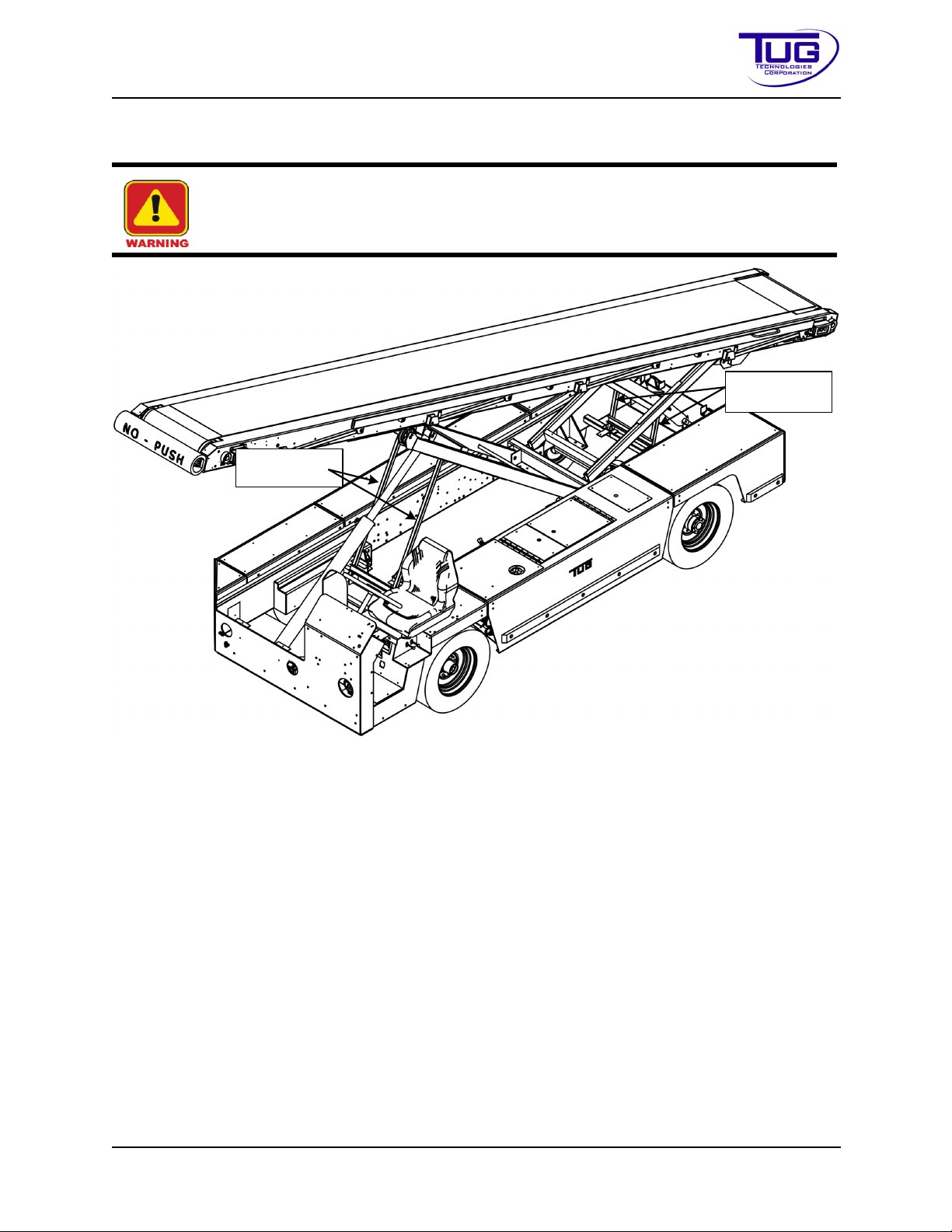
Operation Mobile Belt Loader Model 660
Front Safety
Props
Rear Safety
Props
Operation Manual
2.1.9ConveyorSafetyProps
WARNING: ALWAYS USE THE SAFETY PROPS WHEN WORKING UNDER
THE CONVEYOR.
FigureOperation-2-5BeltLoaderwithPropsEngaged
1. The safety props are provided to support the front and rear of the conveyor for mainte-
nance, checking oil, etc.
2. To engage the safety props:
• raise the front or rear of the conveyor to a height that permits the safety prop to be
rotated to the “UP” position.
• Raise the safety prop to the “UP” position.
CD397-Oper Operation - 2 - 23
Page 86

Mobile Belt Loader Model 660 Operation
Operation Manual
• Slowly let the conveyor down until the safety prop aligns with sockets on bottom of the lift
arm.
CAUTION: Make sure the safety prop is fully engaged inside sockets
before working under the conveyor.
CAUTION: Lower the conveyor GENTLY onto yellow safety props or structural failure may result.
2.2IATA
The following are IATA standards that TUG follows when designing GSE.
• AHM 913: Basic Requirements for Aircraft Ground Support Equipment
• AHM 914: Compatibility of Ground Support Equipment for Aircraft Types
• AHM 915: Standard Controls
• AHM 925: Functional Specification for Self-Propelled Conveyor-Belt Loader
• IATA: Ground Operations Manual (Effective April 2013)
2.3SAE
The following are SAE standards that TUG follows when designing GSE.
• AIR 1336A: Vehicle Electrical Systems
• AIR 1375C: Minimum Safety Requirements for Special Purpose Airline Ground Support
Equipment
• AIR 4286: Maintenance of Ground Support Equipment
• AIR 4905: Wheel Chocks
• ARP1247D: Aircraft Ground Support equipment - General Requirements
• ARP1287A: SAE Standards for Use in the Design of Aerospace, Vehicular Ground
Equipment
• AS4828A: Technical Manual requirements for Ground Support Equipment
2.4ISOEMCEvaluation
The following are ISO EMC Evaluation standards that TUG follows when designing GSE.
• EN 12895: Industrial Trucks Electromagnetic Compatibility
• EN 55011: Radiated Emission
• EN 61000-4-3: Radiated Immunity
• EN 61000 -4-2: ESD Immunity
• EN 12100: Safety of machinery General principles for design
• EN 4413: Hydraulic fluid power General rules and safety requirements
• EN 4413: Hydraulic fluid power General rules and safety requirements
• EN 13849-1: Safety of machinery Safety related parts of control systems
• EN 60204-1: Safety of machinery Electrical equipment of machines
• EN 62061-1: Safety of machines Functional safety of safety related electrical, electronic,
and programmable electronic control systems
• EN 60259: Degrees of protection provided by enclosures
Operation - 2 - 24 CD397-Oper
Page 87

Operation Mobile Belt Loader Model 660
Operation Manual
• EN 12312-3: Aircraft ground support equipment Part 3 Conveyor Belt Vehicle
• EN 1915-1: Aircraft ground support equipment - Part 1 Basic safety requirements
• EN 1915-2: Aircraft ground support equipment - Part 2 Stability and strength requirements
• EN 1915-3: Aircraft ground support equipment - Part 3 Vibration measurement
• EN 1915-4: Aircraft ground support equipment - Part 4 Noise measurement
• EN 1915-4: Safety of machinery Sound level test
2.5ISOProductSafetyEvaluation
The following are ISO Product Safety standards that TUG follows when designing GSE.
• EN 12100: Safety of machinery: general principles for design. Risk assessment and risk
reduction
• EN 4413: Hydraulic fluid power: General rules and safety requirements for systems and
their components
• EN 13849-1: Safety of machinery: Safety related parts of control systems Part 1 General
principles of design
• EN 60204-1: Safety of machinery: Electrical equipment of machines
• EN 60204-1: Safety of machinery: Electrical equipment of machines
• EN 60204-1: Safety of machinery: Electrical equipment of machines
• EN 62061: Safety of machinery: Functional safety of safety related electrical, electronic
and programmable electronic control systems
• EN 60259: Degrees of protection provided by enclosures EN 12312-3 -Aircraft ground
support equipment - specific requirements - Part 3: conveyor belt vehicle
2.6LocationsofTec hn ica lConstructionFiles
The Technical Construction Files are in two places:
1. F2 Labs, Ohio, USA (CE Certifying Body)
2. TUG Technologies Corporation, Kennesaw, GA, USA
The Technical File at TUG will be made available at our premises if requested.
CD397-Oper Operation - 2 - 25
Page 88

Mobile Belt Loader Model 660 Operation
Operation Manual
THIS PAGE INTENTIONALLY BLANK
Operation - 2 - 26 CD397-Oper
Page 89

Operation Mobile Belt Loader Model 660
Operation Manual
Section3:Specifications
This section contains information about the specifications for the Mobile Belt Loader Model 660.
3.1GeneralSpecificationsofthe660
3.1.1Dimensions
Table Operation-3-1:DimensionsandMeasurements
Dimension Measurement
Length 300 in (762 cm)
Width (excluding side bumpers) 78 in (198.1 cm)
Height 59 in (149.9 cm)
Ground Clearance 7.5 in. (19.05 cm)
Wheel Base 110 in (279.4 cm)
Conveyor Length (less front bumper) 294 in (746.7 cm)
Conveyor Width (less side rails) - Standard Width 34 in (86.4 cm)
Conveyor Width (less side rails) - Narrow Width 31.5 in (80 cm)
Belt Width 24 in (61 cm)
Gross Vehicle Weight with Cab 7,200 lb (3266 kg)
Gross Vehicle Weight without Cab 7,000 lb (3175 kg)
CD397-Oper Operation - 3 - 27
Page 90
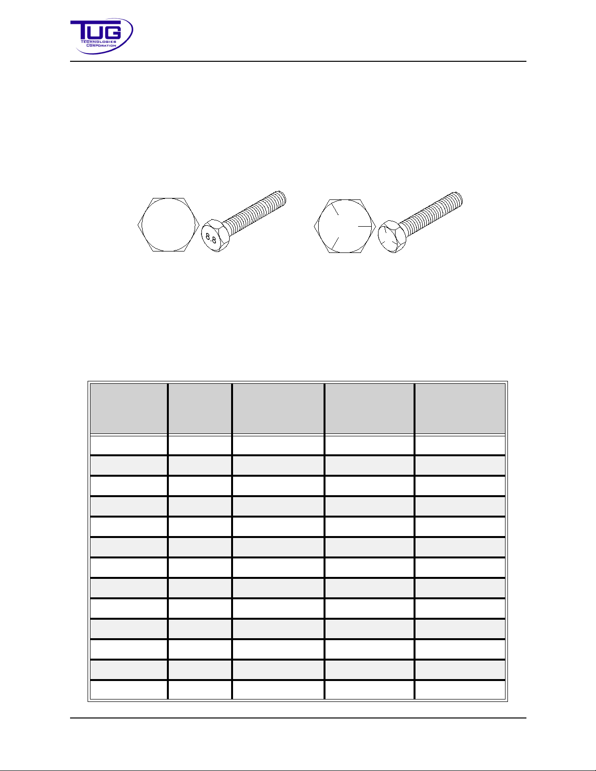
Mobile Belt Loader Model 660 Operation
8.8
Metric Capscrew
Standard Capscrew
Operation Manual
3.2Torq ue Values
Metric capscrews and nuts are identified by the grade number stamped on the head of the capscrew or surface of a nut; while Standard capscrews are identified by a series of lines:
• Grade 5: three (3) lines
• Grade 8: six (6) lines
FigureOperation-3-1:CapscrewExamples
The following torque tables apply to graded metric and standard fasteners used on the Model
660. The listed values apply to bolts threaded into either nuts or tapped holes in iron or steel.
These torque values are not a replacement for torque values specified elsewhere in this manual.
3.2.1MetricFasteners
Tabl e Operation-3-2:TorqueValuesforMetricFasteners
Nominal
Diameter
(mm)
4 0.7 2.576 3.661 4.339
5 0.8 5.288 7.457 8.813
6 1 8.948 12.745 14.914
7 1 14.914 21.422 24.947
8 1.25 21.693 31.048 36.200
10 1.5 42.844 61.283 71.723
12 1.75 74.706 106.974 125.006
14 2 119.448 170.969 199.848
16 2 185.747 265.740 310.482
18 2.5 256.250 366.070 428.438
Pitch
(mm)
Class8.8
(Nm)
Class10.9
(Nm)
Class12.9
(Nm)
20 2.5 362.003 517.922 604.695
22 2.5 493.518 706.381 825.693
24 3 625.032 894.840 1045.336
Operation - 3 - 28 CD397-Oper
Page 91
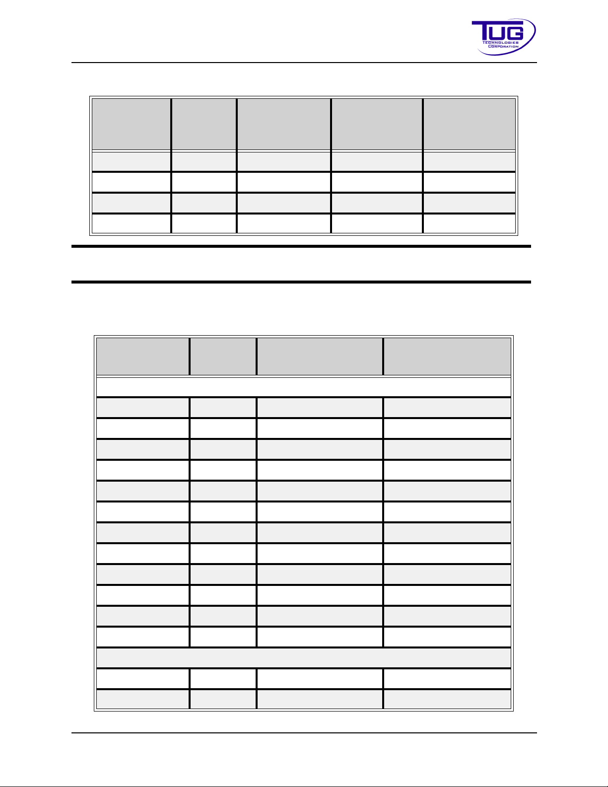
Operation Mobile Belt Loader Model 660
Operation Manual
Table Operation-3-2:Torq ueValues forMetricFasteners(Continued)
Nominal
Diameter
(mm)
27 3 916.533 1312.432 1533.430
30 3.5 1243.285 1778.833 2079.825
33 3.5 1692.060 2421.491 2829.592
36 4 2173.376 3110.246 3634.948
NOTE:
The listed torque values are based on the use of zinc plated, dry threads (or as
received for the 12.9).
3.2.2GradedBolts
Nominal
Diameter(in.)
Pitch
(mm)
Tabl e Operation-3-3:TorqueValuesforGradedBolts
Threads
perInch
Unified Coarse Thread Series
Class8.8
(Nm)
SAEJ429Grade5
(ft-lbs)
Class10.9
(Nm)
SAEJ429Grade8
Class12.9
(Nm)
(ft-lbs)
1/4 20 7.2 10
5/16 18 15 21
3/8 16 26 37
7/16 14 42 59
1/2 13 64 90
9/16 12 92 130
5/8 11 128 180
3/4 10 227 320
7/8 9 365 515
1 8 547 772
1 1/4 7 952 1545
1 1/2 6 1657 2688
Fine Thread Series
1/4 28 8.3 12
5/16 24 16 23
CD397-Oper Operation - 3 - 29
Page 92
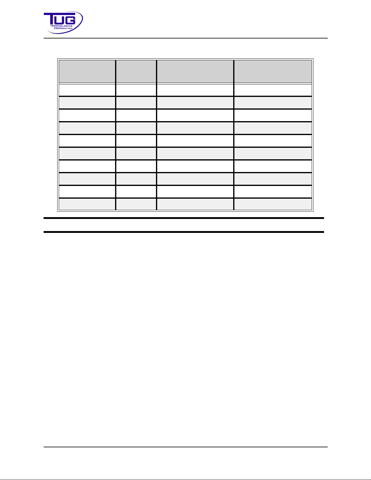
Mobile Belt Loader Model 660 Operation
Operation Manual
Table Operation-3-3:Torq ueValues forGradedBolts(Continued)
Nominal
Diameter(in.)
NOTE:
Threads
perInch
3/8 24 30 42
7/16 20 47 66
1/2 20 72 102
9/16 18 103 146
5/8 18 144 204
3/4 16 253 357
7/8 14 403 568
1 14 614 867
1 1/4 12 1055 1710
1 1/2 12 1865 3024
The listed torque values are based on the use of zinc plated, dry threads.
SAEJ429Grade5
(ft-lbs)
SAEJ429Grade8
(ft-lbs)
Operation - 3 - 30 CD397-Oper
Page 93

Operation Mobile Belt Loader Model 660
Operation Manual
3.3Performance
Tabl e Operation-3-4:PerformanceData
Unit Performance
660 Top Speed 25 mph (43 kph)
Conveyor Capacity (to 15° angle) 2000 lb (907 kg)
Maximum Conveyor Load 2000 lb (907 kg)
Maximum Conveyor Load 200 lb per ft2
(976.4 kg per m
Belt Control Electric
Conveyor Belts Speeds 45 to 90 ft/min (14 to 27 m/min)
Turning Radius 27 ft, measured to the outside front wheel (8.2 m)
Aircraft Capability Will service aircraft with door sills height from 40 to
170 in (101 to 431 cm)
2
)
3.3.1Specifications
Table Operation-3-5: SpecificationData
Item Specification
Battery 12 Volt
Ground Negative
Fuel Tank Capacity 15 gal (US) (56.78 l)
Hydraulic Reserve Capacity 10 gal (US) (37.81 l)
Hydraulic Hose Rating 3000 psi (US) (22.407 MPa)
Service Brakes - Rear Hydraulic, internal-expanding, drum-type, self-adjusting
Service Brakes - Front Hydraulic Disc
Rear Axle Dana, single-speed, limited slip differential, full-floating
Tire and Rims 8.00 x 16.5, 6-ply tubeless on 16.5 x 6.0 G rims
CD397-Oper Operation - 3 - 31
Page 94

Mobile Belt Loader Model 660 Operation
Operation Manual
3.3.2EnvironmentalOperatingLimits
TableOperation-3-6:EnvironmentalLimits
Condition Minimum Maximum
Operating Temperature -25° F (-31° C) 125° F (52° C)
Storage Temperature -25° F (-31° C) 125° F (52° C)
Operating Humidity 0% 100%
Recommended Operating Altitude Sea Level 10,000 Ft (3048 m)
Please contact Tug Technologies for operating procedures in colder environments.
3.3.3EnvironmentalVibrationInformation
The following information covers vibrations transmitted by the machinery to the hand-arm system
or to the whole body:
• The hand-arm vibration does not exceed 8.202 ft/s
2
(2.5 m/s2).
• The highest root mean square value of weighted acceleration to which the whole body is
2
subjected is less than 1.64 ft/s
(0.5 m/s2).
• The measured vibration at the driver's position with the vehicle idling and the belt running
2
at full speed is: 9.843 ft/s
(3.0 m/sec2) pk 5.249 ft/s2 rms (1.6 m/sec2 rms).
• The measured vibration at the driver's position without the belt running is: 4.265 ft/s
(1.3m/s2) pk 1.312 ft/s2 rms (0.4 m/sec2 rms).
3.3.4EnvironmentalSoundInformation
The following diagrams indicate the Sound Pressure Levels (SPL) that were measured in accordance with:
• BS EN ISO 1915-4 Aircraft ground support equipment, General requirements Part 4
Noise measurement methods
• BS EN ISO 11201 Determination of emission sound pressure levels at a work station in
an essentially free field over a reflecting plane with negligible environmental corrections.
2
Operation - 3 - 32 CD397-Oper
Page 95

Operation Mobile Belt Loader Model 660
Driver
71.5
660-28
BS EN 1915 - 4 Noise measurement methods
Belt Loader Stationary
Conveyor Down
Engine Idle
Belt Stationary
1 M from contour and 1.6 M above ground level
All measurements are "A" Weighted dB
69
6967 70 70 71 69
67
6970717272 68.5 68.5
Operator
71
Operator
70
BS EN 1915 - 4 Noise measurement methods
78.5 83.5 82.5 82 8182.5 81
77 8281 81 81 81 78.5
78
Driver
Operator
81
Belt Loader
Stationary
Conveyor Down
Engine Max RPM
Belt Max Speed
78.5
660-28
1 M from contour and 1.6 M above ground level
All measurements are "A" Weighted dB
Operator
80
Operation Manual
All measurements were taken in an acoustic free field over a concrete surface using an Extech
brand SPL meter in the “A” Weighted Mode.
FigureOperation-3-2:Sound-EngineIdle-ConveyorDown-BeltStationary
FigureOperation-3-3:Sound-EngineMax-ConveyorDown-BeltMaxSpeed
CD397-Oper Operation - 3 - 33
Page 96

Mobile Belt Loader Model 660 Operation
39.5 72.5 73 73 73
73
72.5
69 7273 72.5 72.5 72.5
72
72
Driver
Operator
N/A
Operator
72
660-28
BS EN 1915 - 4 Noise measurement methods
Belt Loader Stationary
Conveyor Up
Engine Idle
Belt Stationary
69
1 M from contour and 1.6 M above ground level
All measurements are "A" Weighted dB
BS EN 1915 - 4 Noise measurement methods
81.5 82.5 82 82 8283 81
79.5 8281 82.5 82 82 84
83.5
Driver
Operator
N/A
Belt Loader Stationary
Conveyor Up
Engine Max RPM
Belt Max Speed
79.5
660-28
1 M from contour and 1.6 M above ground level
All measurements are "A" Weighted dB
Operator
80
Operation Manual
FigureOperation-3-4:Sound-EngineIdle-ConveyorUp-BeltStationary
FigureOperation-3-5:Sound-EngineMax-ConveyorUp-BeltMaxSpeed
Operation - 3 - 34 CD397-Oper
Page 97

Operation Mobile Belt Loader Model 660
Operation Manual
3.4Engines
3.4.1Gasoline
3.4.1.1FordMSG-4252.5L
Tabl e Operation-3-7: FordMSG-425(2.5L)
Item Specification
Type In-Line 4-Cylinder
Bore and Stroke 3.50 in x 3.94 in (89 x 100 mm)
Total Displacement 152.5 CID (2.5 L)
Compression Ratio 9.7:1
Firing Order 1-3-4-2
Fuel Unleaded Gasoline or LPG*
Oil Capacity 7.0 qt (6.6 L) with Oil Filter
Alternator Size 95 Amps
*LPGrequiresoptionalfuelsystem
NOTE:
See Ford Operator's Manual for detailed engine data.
3.4.2Diesel
3.4.2.1DeutzD2.9L
Table Operation-3-8:DeutzD2.9L
Item Specification
Type In-Line 4-Cylinder
Bore and Stroke 3.6 in x 4.3 in (92 mm x 110mm)
Total Displacement 176.9 CID (2.9 L)
Compression Ratio 18.4:1
Firing Order 1-3-4-2
Fuel Diesel
Oil Capacity 2 gal (7.57 L)
Alternator Size 95 Amps
CD397-Oper Operation - 3 - 35
Page 98

Mobile Belt Loader Model 660 Operation
Operation Manual
NOTE:
Deutz Operator's Manual for more detailed engine data.
3.5Transmission
The 4-speed automatic transmission is equipped with a torque converter.
3.5.1GearRatios
The following table lists the gear ratios for the transmission.
TableOperation-3-9:GearRatios
Gear Ratios
First 3.059
Second 1.625
Third 1.000
Fourth 2.294
Reverse 2.294
Operation - 3 - 36 CD397-Oper
Page 99
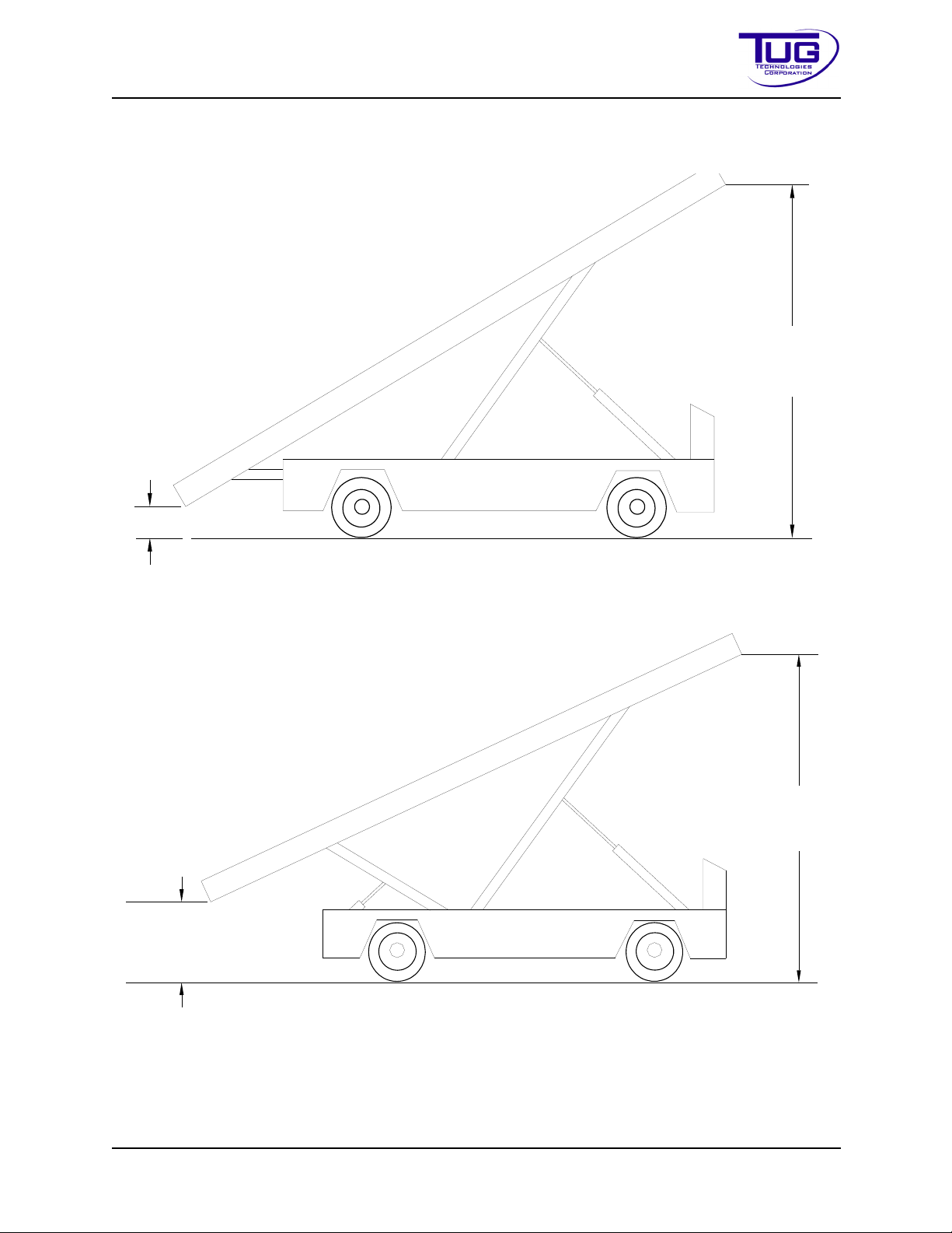
Operation Mobile Belt Loader Model 660
13"(33cm)
170"
(431.8 cm)
37"
(94 cm)
168"
(426.7 cm)
Operation Manual
3.6StandardConv eyorHeightsandAngles
FigureOperation-3-6:Conveyor-FullDownRear,FullUpFront
FigureOperation-3-7:Conveyor-FullUpRear,FullUpFront
CD397-Oper Operation - 3 - 37
Page 100
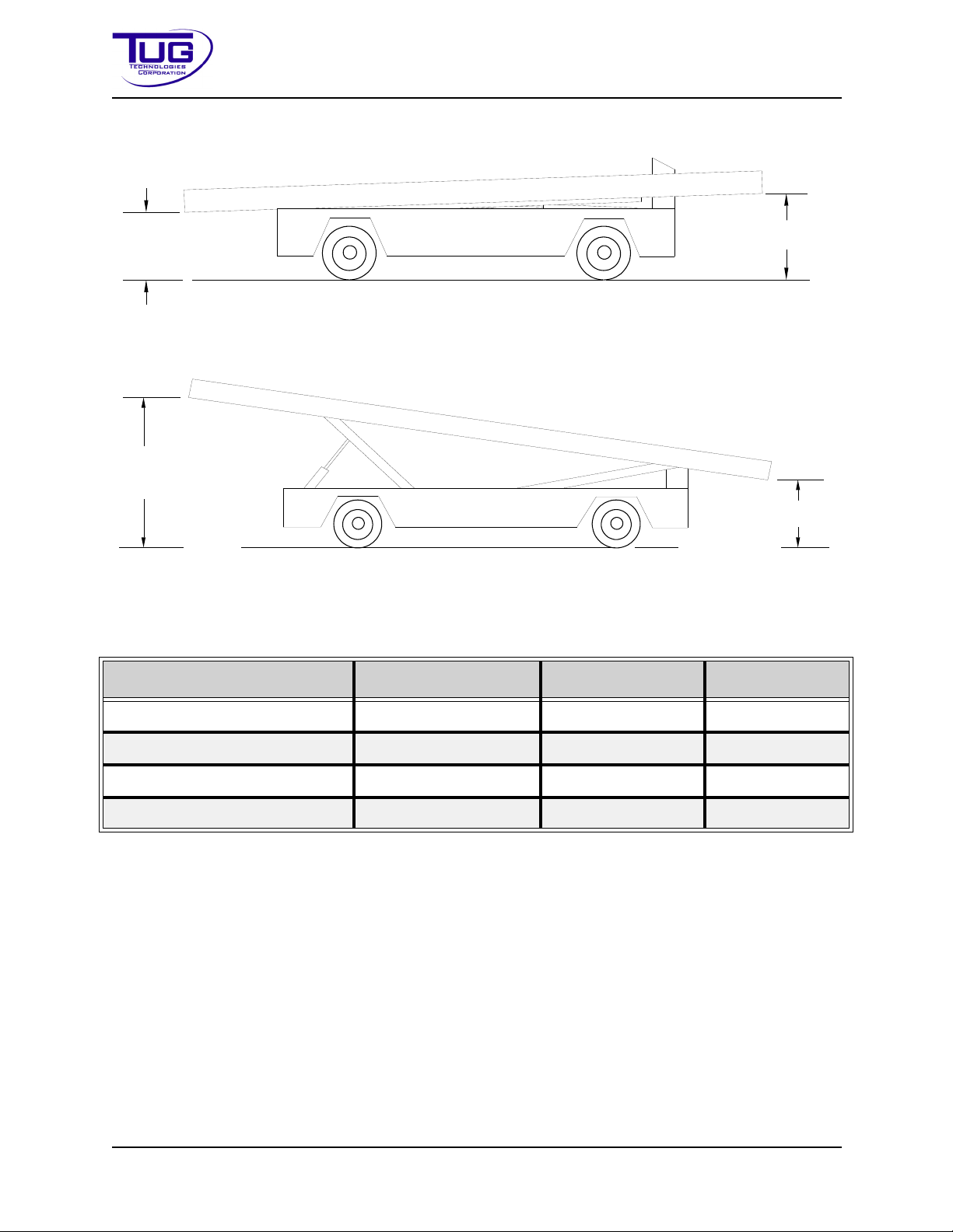
Mobile Belt Loader Model 660 Operation
36"
(91.4 cm)
40"
(101.6 cm)
61"
(154.9 cm)
31"
(78.7 cm)
Operation Manual
FigureOperation-3-8:Conveyor-FullDownRear,FullDownFront
FigureOperation-3-9:Conveyor-FullUpRear,FullDownFront
Table Operation-3-10:ConveyorPositions
ConveyorAttitude Front Rear Angle
Front Up, Rear Down 170 in. (431.8 cm) 13 in. (33.02 cm) 35°
Front Up, Rear Up 168 in. (426.72 cm) 37 in. (93.98 cm) 27°
Front Down, Rear Down 40 in. (101.6 cm) 36 in. (91.44 cm) 1°
Front Down, Rear Up 31 in. (78.74 cm) 61 in. (154.94 cm) -6°
3.7CompatibleAircraft
Table Operation-3-11, “Aircraft Compatibility,” provides a list by aircraft manufacturers and models showing the front and rear cargo door heights with an additional 30 in. (76.2 cm) conveyor
height above the door sill to allow for ease of loading and unloading of cargo. The rear of the conveyor is set at 30 in. (76.2 cm) above ground level.
The listed aircraft are compatible with the Mobile Belt Loader Model 660. The height measurements are from the IATA Airport Handling Manual (AHM) 904 “Aircraft Doors, Servicing Points
and System Requirements for the Use of Ground Support Equipment.”
Operation - 3 - 38 CD397-Oper
 Loading...