

General Note
IRC reserves the right to make changes in product specifi cation without notice or liability.
All information is subject to IRC’s own data and is considered accurate at time of going to print.
A subsidiary of
TT electronics plc
• 4222 South Staples Street • Corpus Christi Texas 78411 USA
© IRC Advanced Film Division
Telephone: 361 992 7900 • Facsimile: 361 992 3377 • Website: www.irctt.com
8900 Series
• Precision absolute and ratio tolerances available
• Qualifi ed to MIL-R-83401 /03, /10 and /15
• Qualifi ed to characteristics M, K and H
• Custom schematics readily available
• Absolute TCR to ±15ppm/°C
Schematic
Resistance
Range
(Ω)
Absolute
Tolerance
Optional
Ratio
Tolerance
Absolute TCR
(ppm/°C)
Tracking
TCR
(ppm/°C)
Element
Power
(mW)
A
10 - 49.9 F, G, J F, G ±50; ±100; ±300 ±20
50
50.0 - 199 F, G, J D, F, G ±25; ±50; ±100; ±300 ±10
200 - 999 B, D, F, G, J A, B, D, F, G ±25; ±50; ±100; ±300 ±5
1.0K - 100K B, D, F, G, J T, Q, A, B, D, F, G ±15; ±25; ±50; ±100; ±300 ±5
101K - 200K B, D, F, G, J A, B, D, F, G ±25; ±50; ±100; ±300 ±5
B
50 - 149 B, D, F, G, J B, D, F, G ±300; ±100 ±50
25
150 - 499 B, D, F, G, J B, D, F, G ±300; ±100; ±50 ±20
500 - 999 B, D, F, G, J B, D, F, G ±25; ±50; ±100; ±300 ±5
1.0K - 150K B, D, F, G, J B, D, F, G ±15; ±25; ±50; ±100; ±300 ±5
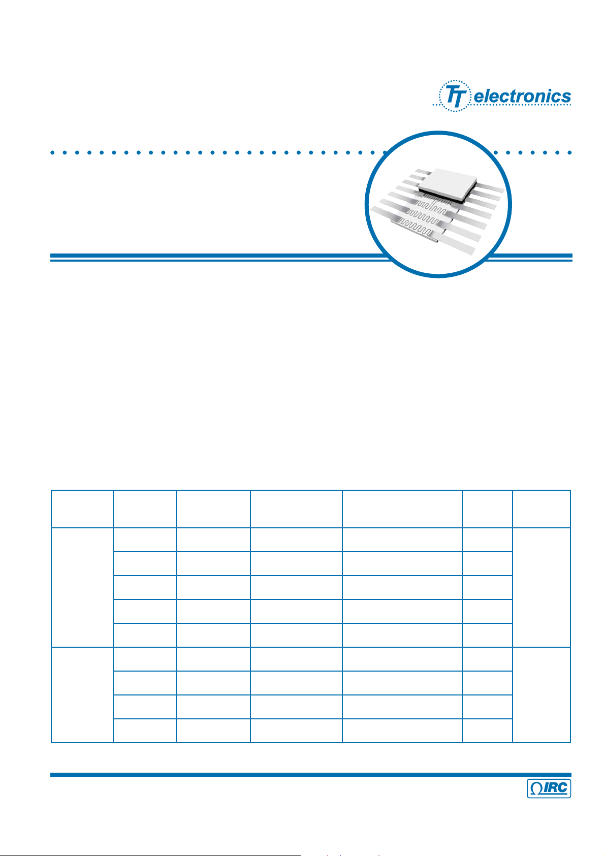
TaNFilm® Precision
Flat Pack Networks
TaNFilm® resistor networks are designed for use in applications requiring a high degree of reliability, stability, tight
tolerance and TCR tracking, and low noise. The sputtering process for resistor formation has been perfected to allow a
continuous feed production line under high vacuum conditions, thus, insuring uniformity of properties between networks.
Laser trimming makes tight ratios easily achievable. The gold plated copper leads are solid phase welded to a large
area of gold conductor pads on the ceramic substrate assuring the most reliable termination and long term stability.
The Tantalum Nitride resistor material is passivated for environmental protection insuring excellent performance far
superior to military requirements.
Our TaNFilm® process enables us to manufacture networks containing different resistance values and still maintain tight
tolerances and tracking characteristics. The nature of our photo-etch process makes it readily adaptable to meet each
individual customer’s needs. Custom circuit designs and special mechanical confi gurations can be easily achieved
with a modest set up charge while maintaining our high standards of precision and reliability.
Electrical Data
8900 Series Issue April 2009 Sheet 1 of 4
• 4222 South Staples Street • Corpus Christi Texas 78411 USA
© IRC Advanced Film Division
Telephone: 361 992 7900 • Facsimile: 361 992 3377 • Website: www.irctt.com
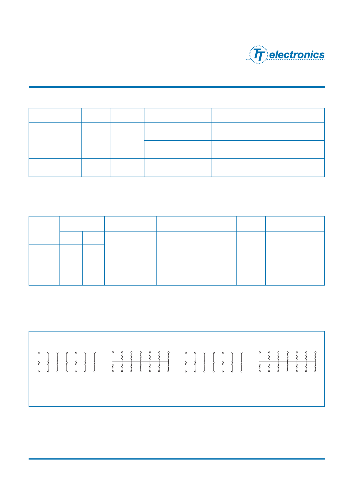
Schematics
R1
R1
1234567
891011121314
1234 567
891011121314
Model 8989
RZ 030, RZ 150
Schematic A
Model 8987
RZ 030, RZ 150
Schematic B
R1
R1
1234567
891011121314
1234 567
891011121314
Model 8999
RZ 100
Schematic A
Model 8998
RZ 100
Schematic B
Schematic
Package Power Power Derating
Voltage
Rating
Temperature
Range
Substrate Lead Finish Noise
14-pin 16-pin
100% from 0°C
to 70°C derated
linearly to 0%
at 125°C
PxR
not to
exceed 50V
-65°C to +125°C
99.6%
Alumina
Gold Plate
(60/40 Sn/Pb
available)
<-30dB
A 350 400
B 325 375
√
_____
Package Specifi cation Data (MIL and Commercial)
TaNFilm® Precision
Flat Pack Networks
Specifi cation Size Schematic Resistance Range (Ω) Absolute Tolerance (%) Characteristic
MIL-PRF-83401/03
MIL-PRF-83401/15
14-Pin A, B
20 - 121K F, G, J K, M
100 - 100K B, D, F, G, J H, K, M
MIL-PRF-83401/10 16-Pin A, B 100 - 100K B, D, F, G, J H, K, M
MIL-PRF-83401 Qualifi cation Data
8900 Series Issue April 2009 Sheet 2 of 4

• 4222 South Staples Street • Corpus Christi Texas 78411 USA
© IRC Advanced Film Division
Telephone: 361 992 7900 • Facsimile: 361 992 3377 • Website: www.irctt.com
Environmental Data
Test per MIL-PRF-83401
MIL-PRF-83401 Limits (ΔR%) TaNFilm® Test Data (ΔR%)
M K H V Max Typical
Thermal Shock and Power Conditioning
0.7 0.7 0.5 0.25 0.1 0.02
Low Temperature Operation
0.5 0.25 0.1 0.1 0.1 0.01
Short Term Overload
0.5 0.25 0.1 0.1 0.05 0.01
Terminal Strength
0.25 0.25 0.25 0.1 0.1 0.01
Resistance to Solder Heat
0.25 0.25 0.1 0.2 0.1 0.02
Moisture Resistance
0.5 0.5 0.4 0.25 0.1 0.03
Shock
0.25 0.25 0.25 0.25 0.1 0.03
Vibration
0.25 0.25 0.25 0.1 0.1 0.03
Life
2.0 0.5 0.5 0.1 0.1 0.03
High Temperature Exposure
1.0 0.5 0.2 0.1 0.1 0.03
Low Temperature Storage
0.5 0.25 0.1 0.1 0.1 0.02
25°C Double Load
2.0 0.5 0.5 0.1 0.05 0.03
0.825″ Max
L
0.250″ ± .010″
0.050″ ± .005″
0.300″ ± .050″
0.017″ ± .002″
0.075″ Max
0.250″ ± .010″
0.005″ ± .001″
0.030″ max miniscus
typ
0.305″ Max
included miniscus
Physical Data
# of
leads
Dimension L
14 0.375″ ± .010″
16 0.390″ ± .020″
TaNFilm® Precision
Flat Pack Networks
8900 Series Issue April 2009 Sheet 3 of 4

• 4222 South Staples Street • Corpus Christi Texas 78411 USA
© IRC Advanced Film Division
Telephone: 361 992 7900 • Facsimile: 361 992 3377 • Website: www.irctt.com
FP 8999 03 1001 B F
Prefi x
Model
8987 = 14-pin Flat Pack, schematic B, gold terminations
8987SD = 14-pin Flat Pack, schematic B, 60/40 Sn/Pb terminations
8989 = 14-pin Flat Pack, schematic A, gold terminations
8989SD = 14-pin Flat Pack, schematic A, 60/40 Sn/Pb terminations
8998 = 16-pin Flat Pack, schematic B, gold terminations
8998SD = 16-pin Flat Pack, schematic B, 60/40 Sn/Pb terminations
8999 = 16-pin Flat Pack, schematic A, gold terminations
8999SD = 16-pin Flat Pack, schematic A, 60/40 Sn/Pb terminations
Absolute TCR
01 = ±100ppm/°C; 02 = ±50ppm/°C; 03 = ±25ppm/°C; 11 = ±15ppm/°C
Resistance
Standard 4-digit MIL resistance code
Example: 1001 = 1000Ω; 50R0=50Ω
Absolute Tolerance
J = ±5%; G = ±2%; F = ±1.0%; D = ±0.5%; B = ±0.1%
Optional Ratio Tolerance to R
1
F = ±1.0%; D = ±0.5%; C = ±0.25%; B = ±0.1%; A = ±0.05%; Q = ±0.02%; T = ±0.01%
Custom schematics and screening available.
Screening available for non-QPL values and tolerances. Contact factory for ordering information.
Commercial Ordering Data
Prefi x
Specifi cation Sheet
03 = 14-pin Flat Pack
10 = 16-pin Flat Pack
15 = 14-pin HI REL Flat Pack
Characteristic
M, K, H
Resistance
Standard 4-digit MIL resistance code
Example: 1001 = 1000Ω; 50R0=50Ω
Absolute Tolerance
J = ±5%; G = ±2%; F = ±1.0%; D = ±0.5%; B = ±0.1%
Schematic
A = Isolated; B = Bussed Schematic
Standard lead termination is gold plate.
Contact factory for optional 60/40 Sn/Pb solder dip finish.
MIL Screened Ordering Data
(MIL-PRF-83401)
M83401 03 K 1001 F A
TaNFilm® Precision
Flat Pack Networks
8900 Series Issue April 2009 Sheet 3 of 4

This datasheet has been downloaded from:
www.EEworld.com.cn
Free Download
Daily Updated Database
100% Free Datasheet Search Site
100% Free IC Replacement Search Site
Convenient Electronic Dictionary
Fast Search System
www.EEworld.com.cn
All Datasheets Cannot Be Modified Without Permission
Copyright © Each Manufacturing Company
 Loading...