

Page 1
Beijing TT Aviation Technology Co., Ltd.
www.ttaviation.com
M8A pro Manual
Beijing TTAviation Technology Co. Ltd.
Page 2
Beijing TT Aviation Technology Co., Ltd.
www.ttaviation.com
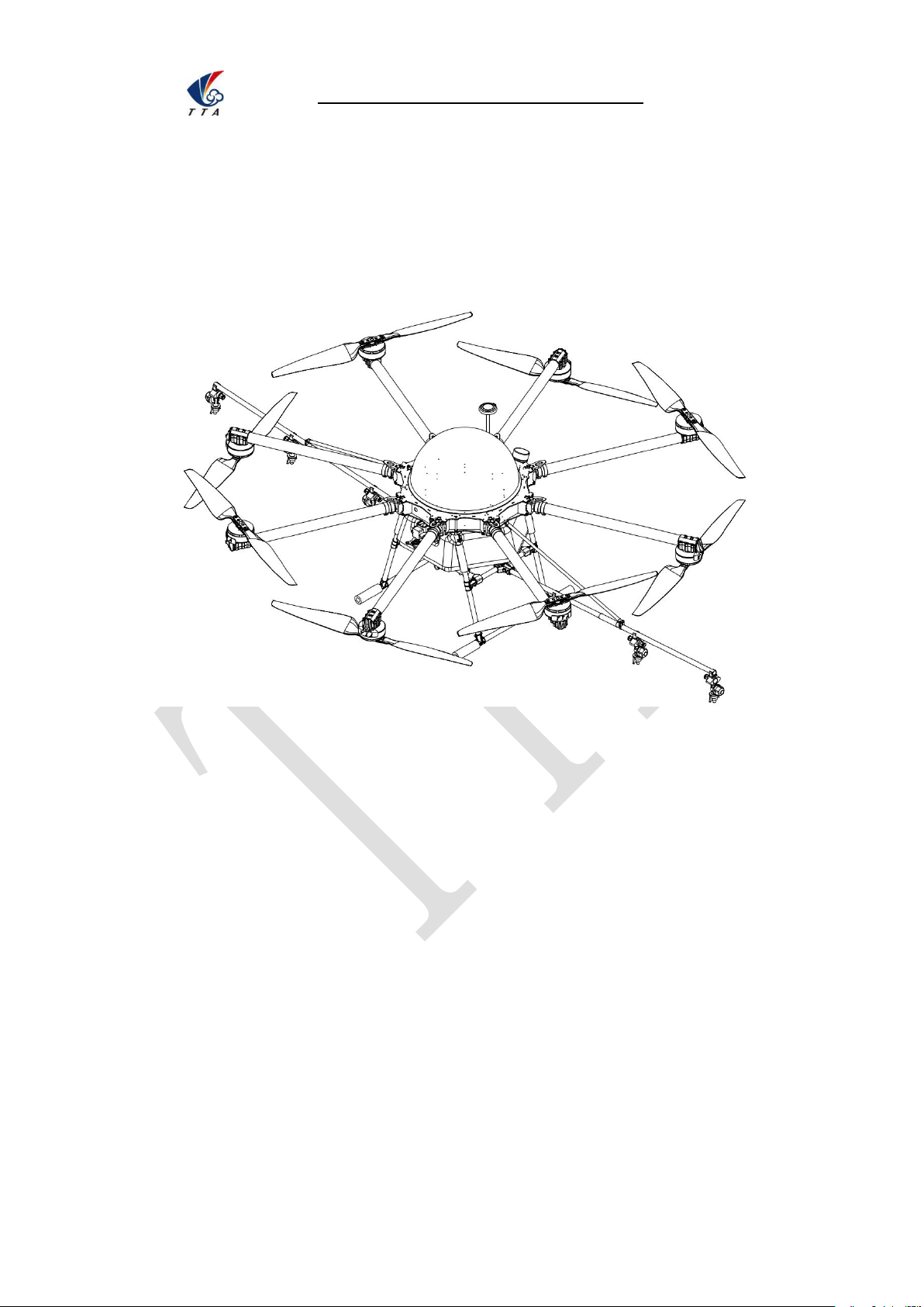
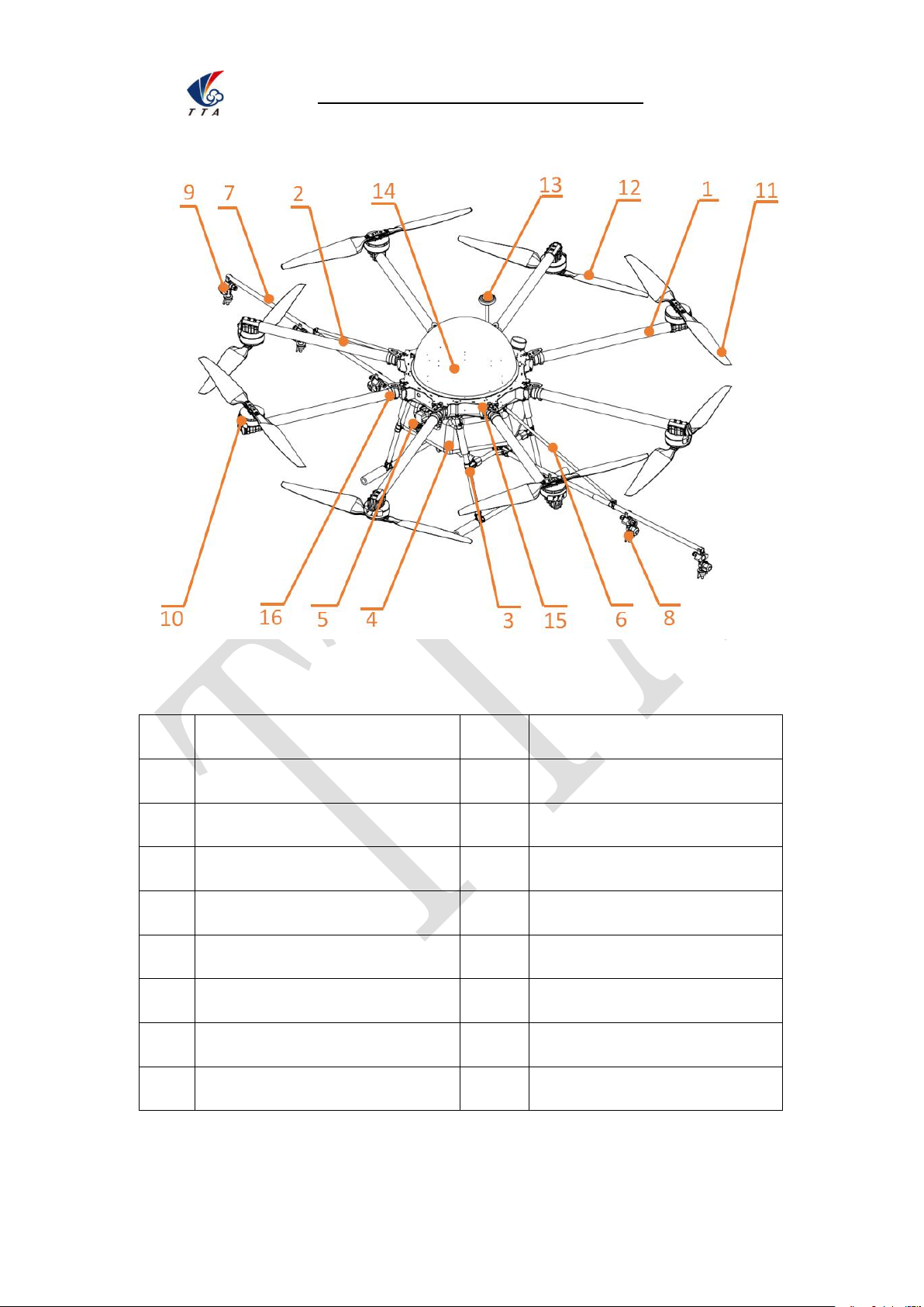
M8A20A1 structural diagram
No.
Component
No.
Component
1
CCW Arm assembly
9
Edge nozzle assembly
2
CW Arm assembly
10
Motor
3
Landing gear assembly
11
CCW Propeller
4
Water tank
12
CW Propeller
5
Pump assembly
13
GPS antenna
6
Holder assembly of spraying rod
14
Dome
7
Spraying tube
15
Up plate
8
Middle nozzle assembly
16
Arm joint jacket
Page 3

Beijing TT Aviation Technology Co., Ltd.
www.ttaviation.com
Catalog
1.Use Instruction
.......................................................................................................................
5
1.1 Safety Instruction
.......................................................................................................
5
1.2 Pesticide Usage
.........................................................................................................
6
1.3 Inspection
....................................................................................................................
7
1.4 Environment
................................................................................................................
8
1.5 Operation
.....................................................................................................................
8
1.6 Compass Calibration Requirements
.......................................................................
9
2. Product Introduction
..........................................................................................................
10
2.1 Flying Parameters
...................................................................................................
11
2.2 Copter Parameters
..................................................................................................
11
2.3 Packing List
..............................................................................................................
13
3.Preparation Before Take Off
..............................................................................................
14
3.1 Device Installation
...................................................................................................
14
3.1.1 GPS Antenna Installation
............................................................................
14
3.1.2 Arm Installation
.............................................................................................
15
3.1.3 Propeller installation
....................................................................................
16
3.1.4 Sprayer Supporter Installation
...................................................................
17
4. Charger Instruction
............................................................................................................
19
4.1 Product Application
..................................................................................................
19
4.2 Product Features
.....................................................................................................
19
4.3 Main Technical Parameters and Application Demand
.......................................
19
4.4 Interface Indicator
....................................................................................................
20
4.5 Function and Operation Instruction
......................................................................
21
Page 4

Beijing TT Aviation Technology Co., Ltd.
www.ttaviation.com
4.6 Attention
.....................................................................................................................
21
5. App Setting of Copter
........................................................................................................
22
5.1 Software Configuration
...........................................................................................
22
5.2 Parameters adjustment
...........................................................................................
23
Type 1: Connection by OTG cable
......................................................................
23
Type 2: Connection by Bluetooth connection:
...................................................
25
5.2.1 Remote controller calibration
.....................................................................
29
5.2.2 IMU calibration
..............................................................................................
30
5.2.3 Compass calibration
....................................................................................
31
5.2.4 Flying parameters adjustment
....................................................................
32
5.2.5 Low voltage protection
................................................................................
33
5.2.5.1 Low voltage protection settings
......................................................
33
5.2.5.2 Alarm voltage settings
......................................................................
33
5.2.5.3 Voltage calibration settings
.............................................................
34
5.2.5.4 Pump and liquid level sensor settings
...........................................
34
5.2.5.5 Tank empty reaction
.........................................................................
34
5.2.6 About interface
..............................................................................................
35
5.3 Route establish
........................................................................................................
35
6. Remote Controller
..............................................................................................................
41
6.1 Function description
................................................................................................
44
6.2 Bind
............................................................................................................................
44
6.3 Remote controller antenna direction
....................................................................
46
6.4 How to change between mode 1 and mode 2
....................................................
46
7. Function Control
.................................................................................................................
46
Page 5

Beijing TT Aviation Technology Co., Ltd.
www.ttaviation.com
7.1 Flight Mode
...............................................................................................................
46
7.2 AB Mode
....................................................................................................................
47
Appendix I Implication of Indicator Light
....................................................................
49
Appendix II How to connect copter to PC GCS
........................................................
51
Appendix III How to download log from PC GCS
......................................................
53
Appendix IV How to upgrade the firmware
.................................................................
53
Disclaimer
................................................................................................................................
54
Page 6

Beijing TT Aviation Technology Co., Ltd.
. Use Instruction
5
1.
1.1 Safety Instruction
The product is not suitable for the ones who are less than eighteen or who do not have
The product have bigger fuselage size, high speed rotary and strong flight dynamics.
When using this product, please keep away from airport, railroad, high speed road,
When using this product, please keep away from mobile phone base stations, high
When using this product,please keep away from army and kinds of manned craft flight
Don’t use this product in rain, thunder, sandstorm, fog snow ,high wind ,and low
When flying in more than three kilometers. Environmental factors can lead to flight
When operating this product fly in low sky .Please always keep UAV and people &
When using this product in desert area, please keep UAV within the range of
Don’t hover or fly over the crowd, Don’t be delight in scaring others.
Use Instruction
full capacity for civil conduct.
At runtime have a certain dangerousness . Not in accordance with the requirement
operation and usage will cause to potential danger and hurt.
high buildings ,electric wire and other dangerous environments.
power transmitting equipment, and other high electromagnetic interference
environments.
area.
temperature and other bad environments.
performance degradation, please care of using it.
animals in a safe distance of ten meters
operator’s eyes
Page 7

Beijing TT Aviation Technology Co., Ltd.
. Use Instruction
6
When it is close to the crowd ,please land this UAV as soon as possible and guide
people to keep and avoid potential accident.
Don’t operate it in the area of children playing.
If not in the extreme necessary condition, please do not power off when flying in the
You can not fly it you are in drinking , tied, drugs, physical ,discomfort, etc. .
Please inspect it before using very time, including but not limited to parts of fastness,
Abnormal working state of the UAV maybe happen accidentally, don’t open the
Do not try to prevent the moving parts while working.
1.2 Pesticide Usage
All pesticides are poisonous. Please be careful and work strictly according to the
When dispensing, please use clear water. If not, will cause jams mesh of impurities. If
When dispensing , please note that liquid sparks and the pesticide residue in fuselage
When dispensing, please pay more attention and use protective tools, and do not let
air.
organism and propeller of cracks, and abrasion ,battery ,the effectiveness of light.
When error happens, please stop using immediately and replace the corresponding
parts.
propellers and forcibly fly with wrong.
safety instructions of pesticides.
it is blocked, please clear it before reuse
will be harmful to human body.
body directly touch with the pesticides; After pesticide spraying, please clear your skin,
copter and remote control.
Page 8

Beijing TT Aviation Technology Co., Ltd.
. Use Instruction
7
When using pesticide, there will be interaction between different pesticides , user
should clear cartridge or keep a certain interval time。
Spraying shall be carried out in windless sunny day, don’t spray under high
When spaying ,if you feel uncomfortable ,headache or dizzy, please leave the site at
Pesticide effect and the solution concentration, spray rate ,copter high from
When using pesticide , do not pollute river and drinking water
1.3 Inspection
Before flying, ensure the battery is enough
Ensure all the parts are installed firmly, and all the screws are tight as required.
Ensure all the wires are correctly linked.
Ensure all parts goes well. If it is broken or aging, please replace timely.
Before flying, carefully check the propellers installation direction 、 rotation direction,
Ensure all the propellers are fine, no any scratch and tightly installed.
Ensure the sprayer is fluent without any clogging and work normally.
temperature at noon. While breezing, the operator should be standing above the wind
and spraying; do not work when wind is four.
once and rest. If once severe symptoms occur, immediately be sent to hospital.
crops ,wind direction, wind speed and so on are close related. When using pesticide
should consider the above factors, to achieve the best effect. Please make sure that
do not damage the human beings and animals and surroundings during the process of
sprayings.
control and others.
Page 9

Beijing TT Aviation Technology Co., Ltd.
. Use Instruction
8
1.4 Environment
While flying, please ensure the drone away from the crowds, dangerous goods, high
buildings, high-voltage wires and others. Please fly the drone in a dedicated space.
Please ensure the drone fly within the operator’s eyesight.
The drone working temperature is between 0℃-40℃.
Ensure the drone fly within the permit of local law and regulations.
To fly the drone safely as required, please fly it within in the height of 50 meters. If it
1.5 Operation
Please ensure the multi-rotor drone flying height is within 8 meters, except the special
Before remote control calibration、hardware update, parameter setup, please remove
Remove the battery if it does not fly, to avoid flying it when touching the remote control
Please remove the batteries once landing. Do not move the drone when it is in power.
Do not touch the joy stick mistakenly, and prevent start the drone.
When it is powered, please stand in the safe distance of above 10 meters.
Ensure the propellers completely stop and power off.
Please switch it to the manual operation mode when errors happen. When the manual
has local flying height limit within 5ometers, please make sure obey the related
regulations.
requirements.
the propellers and avoid the potential moving suddenly.
once.
operation mode does not work, please press the emergency bottom. Please keep
Page 10

Beijing TT Aviation Technology Co., Ltd.
. Use Instruction
9
away from the crowd.
When the battery is damaged, please ensure it is stored in the disposal area and avoid
During the flight, don’t fly overload and do not cause any potential dangers.
When low battery is warning, please return as soon as possible.
Ensure that the remote control and battery is enough, to ensure that firmware has
Ensure flying sites outside of the restricted areas and is proper for flight . .
Please make sure do not fly or operate the drone when you are drunk or with medicine
Be familiar with the remote control operation & each flight mode, and ensure you
User shall know and obey all the law and regulations in flying location.
1.6 Compass Calibration Requirements
Compass has to be calibrated before using the first time. If else, it cannot work and will
Please do not calibrate it in the place close to the high-magnetic field or big metal
When calibrating, please do not bring the magnetic materials, such keys and
If it is calibrated indoor, please do not re-calibrate it outdoor. It prevents that the two
spontaneous combustion. In order to protect environment, please don’t throw batteries
randomly. And consult the maker about the proper disposal method.
been updated to the latest version.
limitation.
know how to operate the control condition.
affect flying safety. Calibration tips:
materials, such as high-voltage, magnet, parking lot, concrete iron building, etc.
cellphone.
magnet differences cause the potential flying data errors.
Page 11
Beijing TT Aviation Technology Co., Ltd.
. Use Instruction
10
Magnetic field location is different, please make sure re-calibrate when it changes to
the place far away from the previous one.
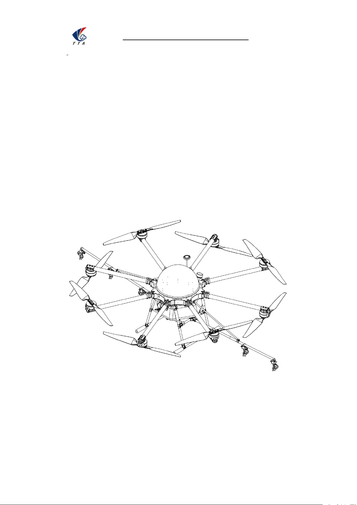
2. Product Introduction
M8A20A1, the multi-rotor UAV, is the most economic integrated solution for all the
agriculture spraying services,the product series payload is up to 20kg.This UAV use
carbon fiber material,the saving weight could be used to payload. The big power
brushless motor guarantees the sensitiveness and flexibility. The Lipo batteries guarantee
the power supply and easy to repair and maintain. Various spraying tests proves the best
performances of this UAV for many years.
Page 12
Copyright © 2017 TTAAll Rights Reserved. Appendix Implication of indicator light
11
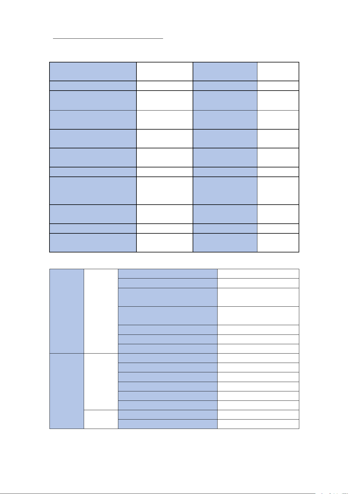
2.1 Flying Parameters
2.2 Copter Parameters
Frame
Frame
Diagonal Wheelbase
1630mm
Arm Length
632mm
Unfolded Height
600mm(top shield 200mm
not included)
Folded Height
710mm(top shield 200mm
not included)
Folded Width
570mm
sprayer supporter length
3180mm
Sprayer Distance
500-550mm(adjustable)
dynamic
system
Motor
Motor Model
TTA8017-2
Stator Size
75mm
KV
120KV
Max Thrust
14KG
Max Power
2300W
Weight
640g
ESC
Max Continuous Working Current
80A
Max Peek Current(3s)
120A
Copter weight
(without battery)
18 KG
Max pitch angle
≤35°
Standard take off weight
46 KG
Best working speed
4-6m/s
Max effective take off weight
48 KG
Max working speed
10m/s
Max thrust weight ratio
2.43(take off
weight 46Kg)
Working time
10-15min
/sortie
Dynamic battery
16000/17000mAh
*4pcs
Max ascending
speed
5m/s
Max power consumption
18400W
Max descending
speed
3m/s
Hovering power consumption
5400W
Max flying speed
15m/s
Hovering time
empty≥25min
full≥6min
Recommended
working environment
temperature
10-35C°
Hovering accuracy
horizontal±1.5m
vertical±0.5m
Max wind resistance
12m/s
Working height
2-4m
Max flying altitude
3500m
Max rotation angle
360°
Best reserving
temperature
10-25C°
Page 13

Copyright © 2017 TTAAll Rights Reserved. Appendix Implication of indicator light
12
Max Allowed Voltage
14S LiPo
Working Voltage
12S(44-50.4v)
Working Pulse Width
1000-2000us
Compatible Signal Frequency
50-400Hz
Drive PWM frequency
400Hz
Propellers
Material
Carbon fiber
Diameter /Screw pitch
3080(length 760mm)
Weight
110g
Battery
Capacity
16000mAh/17000mAh
spraying
system
Water
Tank
Payload
20L
Sprayer
Model No.
pressure type(hollow cone)
Quantity
6 pcs
Sprayer Diameter
0.67mm
Spraying Speed
4--6m/s
Spraying Volume
1.8--2.2L/min
Spraying Width
5--8m(up to height)
Spraying Droplet Diameter
80--200μm(adjustable)
Remote
controller
Remote
controller
Type
R3
Working frequency
2.4Ghz
Signal effective distance(without
interference and block)
800m
Battery capacity
3.7V,3000mAh
Charging type
direct
Working environment temperature
0-40C°
Reserving environment
temperature
10-25C°
Best charging environment
temperature
10-25C°
Page 14
Copyright © 2017 TTAAll Rights Reserved. Appendix Implication of indicator light
13
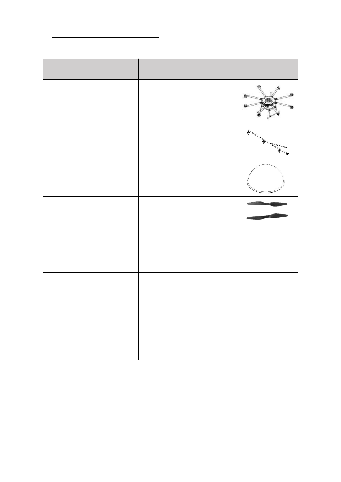
2.3 Packing List
Name
QTY
Image
Fuselage
1pcs
Spraying rod assembly
2 pcs
Dome
1 pcs
Propeller
4 pair
T8FG remote controller
1 pcs
M8A20A manual
1 pcs
A4 adhesive sticker print paper
1 pcs
Spare part
Tools box
1pcs
TTA spanner
1 pcs
LiPo battery
charger
1 pcs
Electric quantity
indicator
1 pcs
Page 15

Copyright © 2017 TTAAll Rights Reserved. Appendix Implication of indicator light
14
3.Preparation Before Take Off
3.1 Device Installation
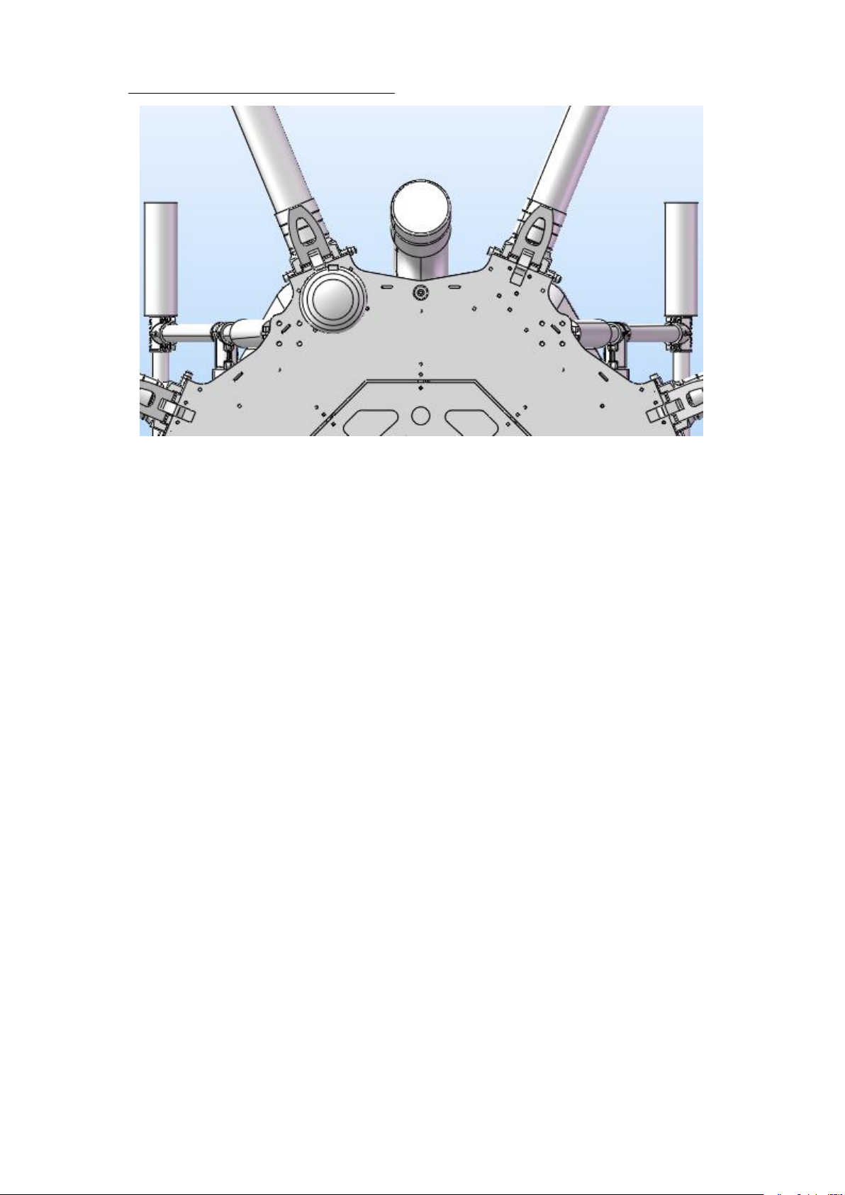
3.1.1 GPS Antenna Installation
spare screw
M3*8 cylinder head 5 pcs
M3*8 half round head 5 pcs
M4*60 cylinder 2 pcs
M4*65 positioning bolt 2 pcs
aviation box
optional
16000mAH/17000mAH
battery
optional
Dual channel 6s charger
optional
Four channel 6S
optional
It’s very important to the steps of before take off,please check carefully and ensure the
copter qualified before take off.
Parts and lines have been installed well before copter sending out of the factory,please do
not change any position of part and line and follow the following steps is enough to work.
Step 1:erect GPS supporter,be careful that GPS supporter is vertical to the horizontal
direction.
Step 2: tighten the nut on the bottom.
Page 16
Copyright © 2017 TTAAll Rights Reserved. Appendix Implication of indicator light
15
Figure 3-1 GPS installation effect picture
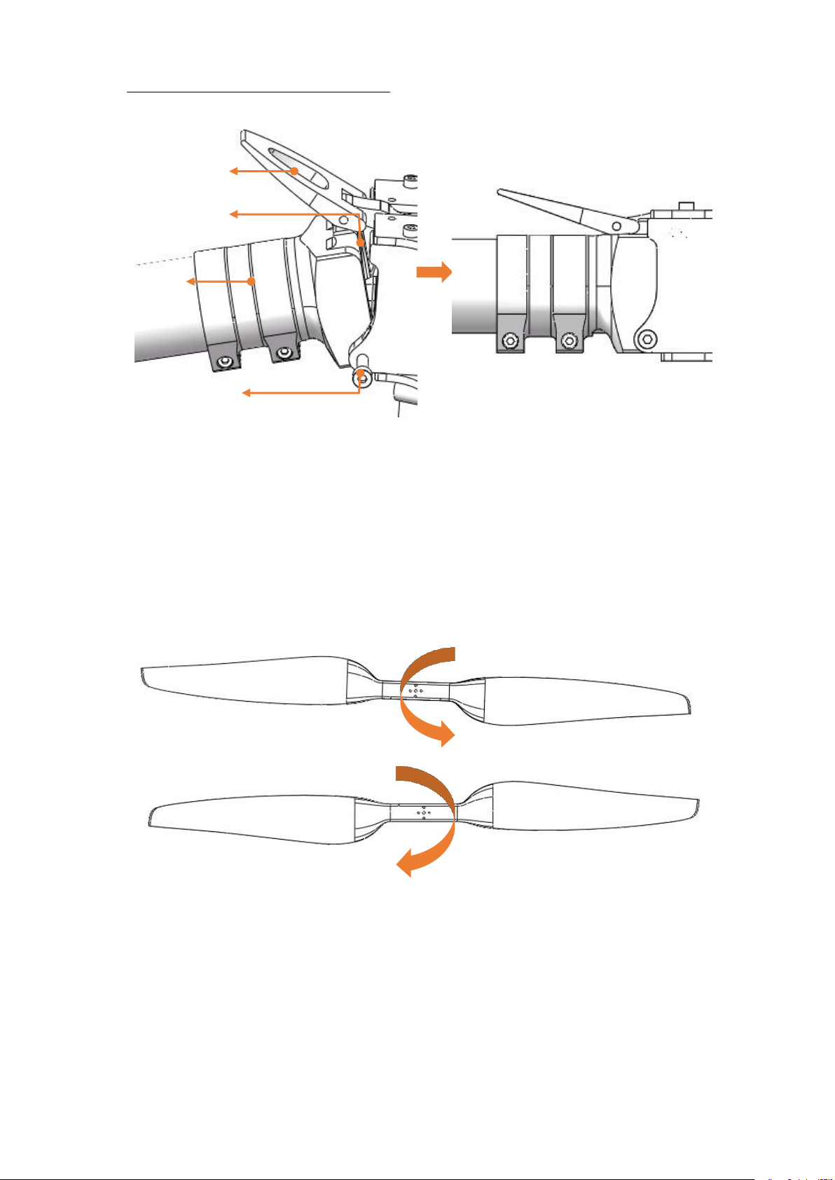
3.1.2 Arm Installation
Use a M4*65 bolt to connect arm and frame and then tighten the bolt and operate the
spanner. The other arms are same step.
Page 17
Copyright © 2017 TTAAll Rights Reserved. Appendix Implication of indicator light
16
3.1.3 Propeller installation
Step 1: just the propeller type,CCW or CW.
CW
CCW
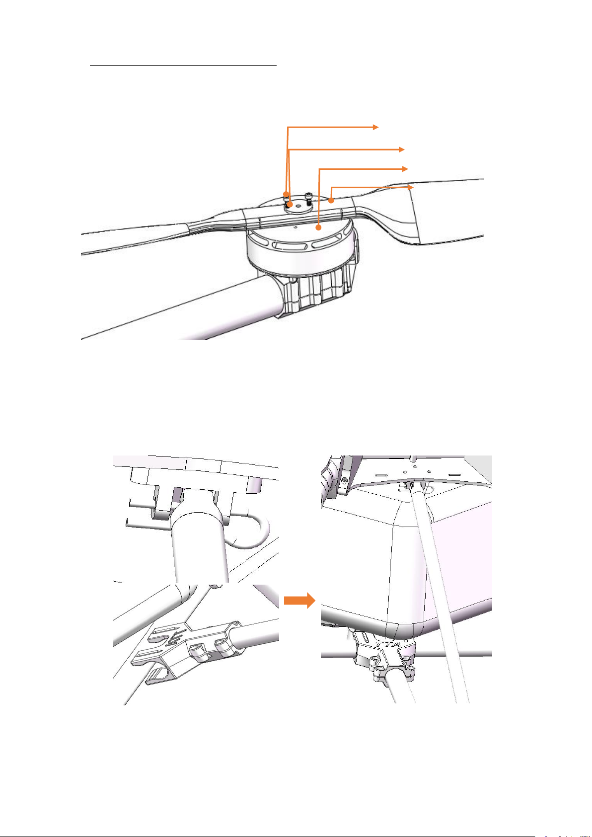
Step 2: propeller installation,propeller first,then gasket,tighten 2 pieces of M3*14
Bolt M4*65
connector
Spanner
arm
Effective picture
Figure 3-2 arm installation
Figure 3-3 propeller type
Page 18
Copyright © 2017 TTAAll Rights Reserved. Appendix Implication of indicator light
17
bolt(M1,M3,M5,M7 is CCW,and M2,M4,M6,M8 is CW).
Figure 3-4 propeller installation effective figure
3.1.4 Sprayer Supporter Installation
Step 1: connect the sprayer and its connector,see figure3-5.
Step 2: pin the diagonal member and pin it through.
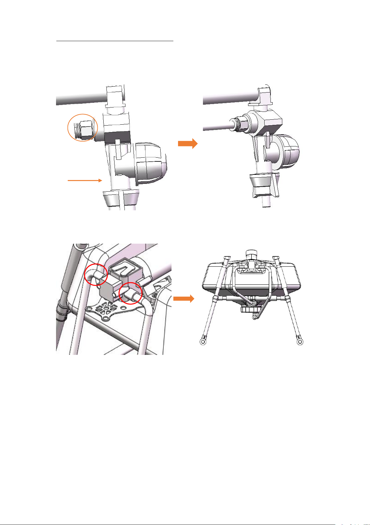
Bolt M3x14(2 pcs)
Gasket
Motor
Propeller
Figure 3-5 Sprayer supporter connection effect picture
Page 19
Copyright © 2017 TTAAll Rights Reserved. Appendix Implication of indicator light
18
Step 3: connect pipe(5mm*8mm) between pump outlet and sprayer,and the other sprayer.
Press direction
connector
Pressing the connector when loosing the pipe.
Figure 3-6 pipe connection in sprayer supporter
Figure 3-7 pipe connection in pump outlet
Step 4: repeat step 1 to step 3 for the other sprayer supporter.
Page 20

Copyright © 2017 TTAAll Rights Reserved. Appendix Implication of indicator light
19
4. Charger Instruction
4.1 Product Application
LiPo 6s balance charging
4.2 Product Features
1. balance charging
2. quick charging
3. input and output reverse polarity protection
4. Low static power
4.3 Main Technical Parameters and Application Demand
1. Input voltage: AC 220V
2. Max charging current: CH1:20.0A;CH2:20.0A
3.Max charging power:CH1:500W;CH2:500W
4. Average output voltage:CH1:25.2V;CH2:25.2V
5. Max output voltage:27.0V
6.Max balance current:400mA
7.Max static power:2400mW
8.Display mode:LED display
9. Support battery cell number:6S
10. Charger working temperature:0~40℃
Page 21
Copyright © 2017 TTAAll Rights Reserved. Appendix Implication of indicator light
20
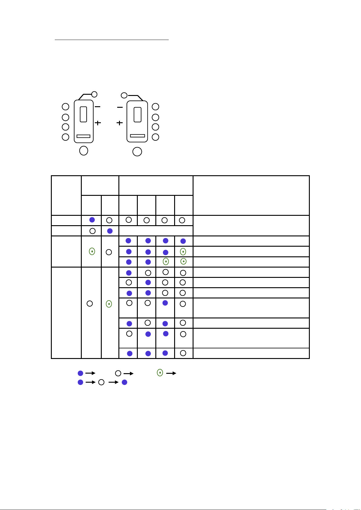
4.4 Interface Indicator
Charging
indicator
Output
status
indicator
CH1
CH2
Dual channel6S-20A charger
Blance port
Charging
status
Charging
indicator
status indicator
Note
gree
n
red
LED1LED2LED3LED
4
Idle
charging
Note 2
full
charging status:good,balance well
charging status:common,balance commonly
charging status:poor,balance poor
abnormal
charging module abnormal
balance port connection abnormal
input voltage abnormal
output voltage abnormal,check output
connection with battery
single cell high voltage alarm
battery inspection fail,check balance port and
output port
no charging current,check output connection
Charging
indicator
status
indicator
Note1: ON OFF flash
Note2: :LED1-LED4 flash in turn circularly,means charging in real
time
Fast cycle speed:big electric current change
Slow cycle speed:charging near full
Page 22

Copyright © 2017 TTAAll Rights Reserved. Appendix Implication of indicator light
21
4.5 Function and Operation Instruction
1.Connect with power,leave switch at OFF position,charging channel outside is
close,charging indicator is OFF.
2. Connect with power,leave switch on external power,external power supply
open,charging indicator is green,charging channel is OFF.
3. Connect with power,press start button for 2s,charging channel is open,charging
indicator means current status,charging status is red ON.
4.Press start button during charging process and exit charging mode;press start
button when abnormal which means exit abnormal status.
5. It is suggested to charge for a while if not balanced well, which can prolong the
lifetime of the battery.
4.6 Attention
1.Over low or high charger input voltage may lead to abnormal status or damage.
2. Please observe the instruction strictly.
Page 23
Copyright © 2017 TTAAll Rights Reserved. Appendix Implication of indicator light
22
5. App Setting of Copter
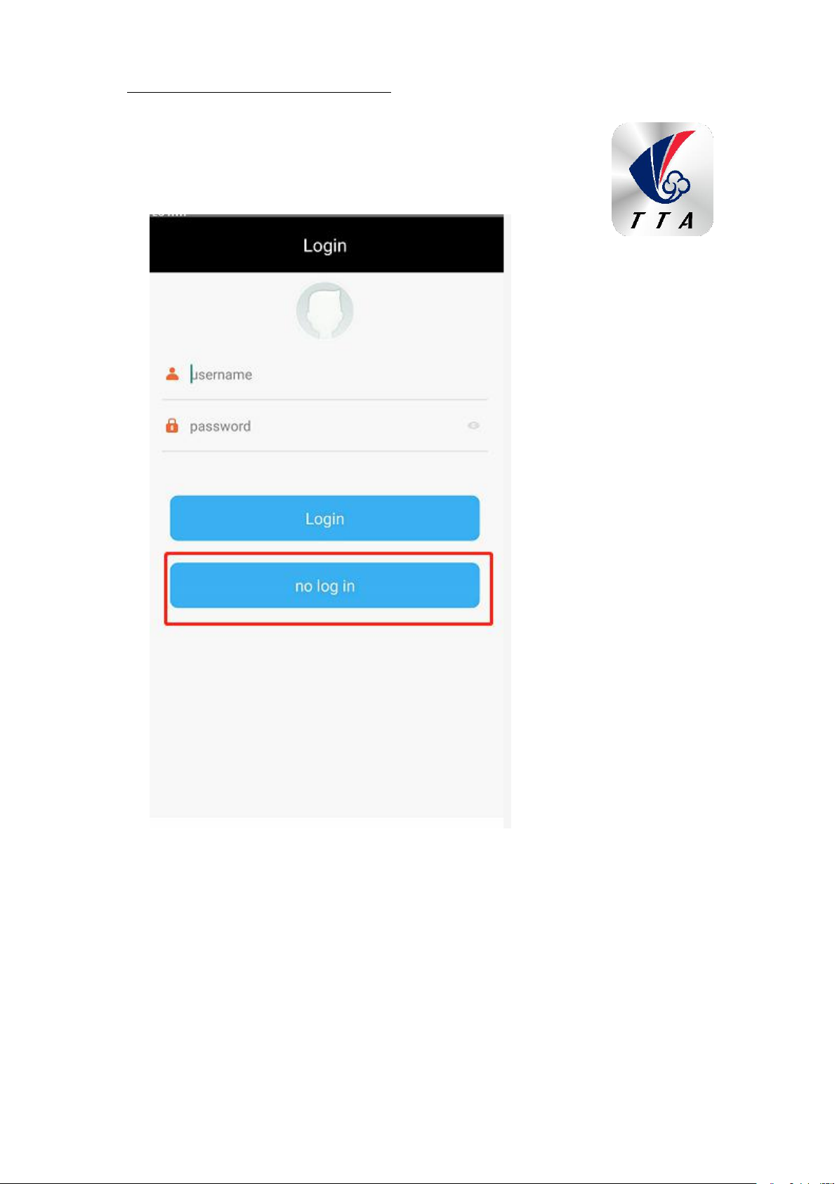
Please choose no log in.
5.1 Software Configuration
1. Please install the GCS software.
2. After GCS installation,the label will be appeared as figure 5-1.
Figure 5-1
Page 24
Copyright © 2017 TTAAll Rights Reserved. Appendix Implication of indicator light
23
TTA-M6E-1 support Android 4.0 or above
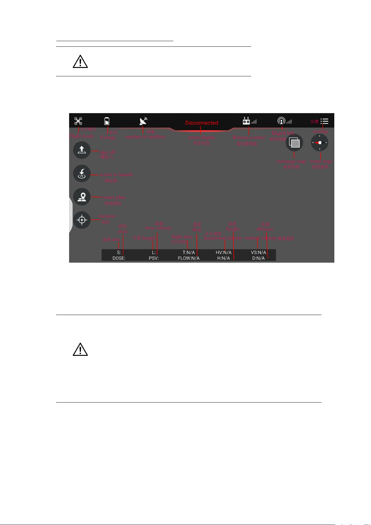
3. Open GCS,enter into the start page.
4. Enter into the main page ,see figure 5-2.
5.2 Parameters adjustment
Type 1: Connection by OTG cable
Sensitivity should not be changed by common user,the unnecessary
loss should be taken by user for authorized changing.
Remote controller could not unlock before parameters adjustment.
Exit could only be done when all of the parameters adjustment should
be done and confirmed.Copter could only fly by restarting after
parameters adjustment.
Parameters could be adjusted when copter connected,the steps are as followings:
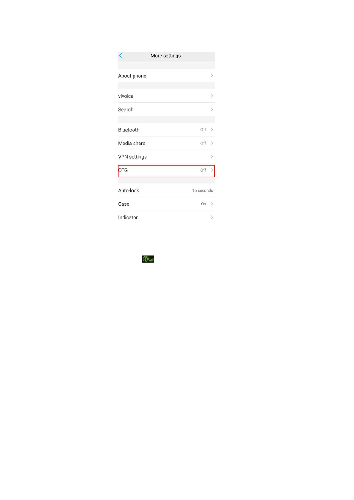
1) Open the OTG function from cellphone SETTINGS---SYSTEM---OTG(the default
is Off thus it should be opened every time),see figure 5-2-1.
Page 25
Copyright © 2017 TTAAll Rights Reserved. Appendix Implication of indicator light
24
Figure 5-2-1
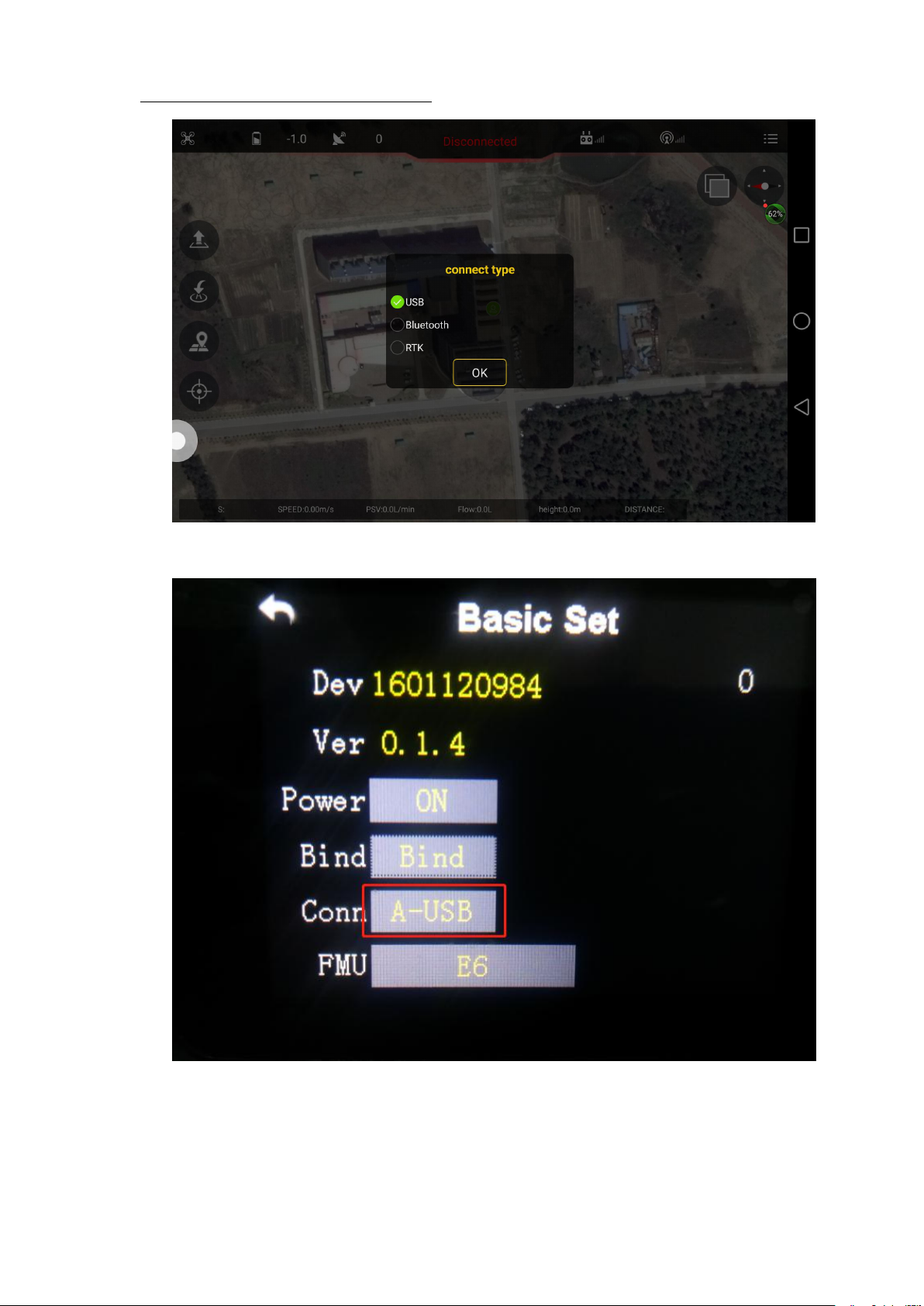
Connect cellphone with Micro USB port of remote controller.The connection method
should be USB,connection label will be green after connected,see figure 5-3
Page 26
Copyright © 2017 TTAAll Rights Reserved. Appendix Implication of indicator light
25
Remote controller should be selected to A-USB,see the following picture:
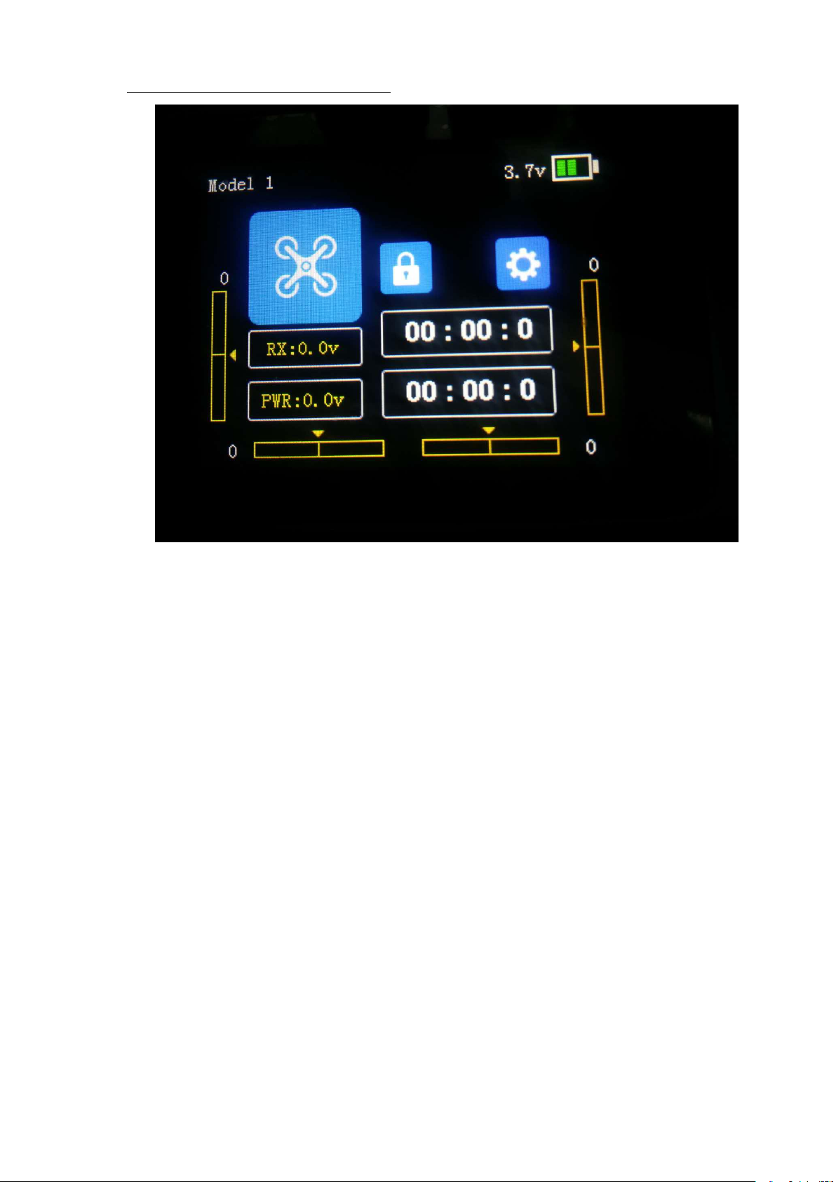
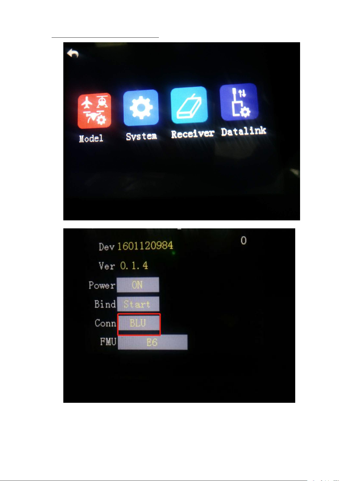
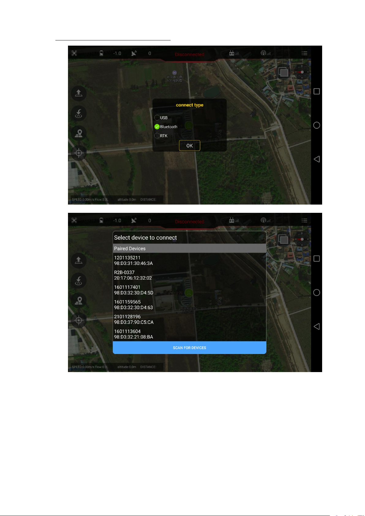
Type 2: Connection by Bluetooth connection:
Open the bluetooth function in cellphone,
Page 27
Copyright © 2017 TTAAll Rights Reserved. Appendix Implication of indicator light
26
Page 28
Copyright © 2017 TTAAll Rights Reserved. Appendix Implication of indicator light
27
Page 29
Copyright © 2017 TTAAll Rights Reserved. Appendix Implication of indicator light
28
Bluetooth password:1234
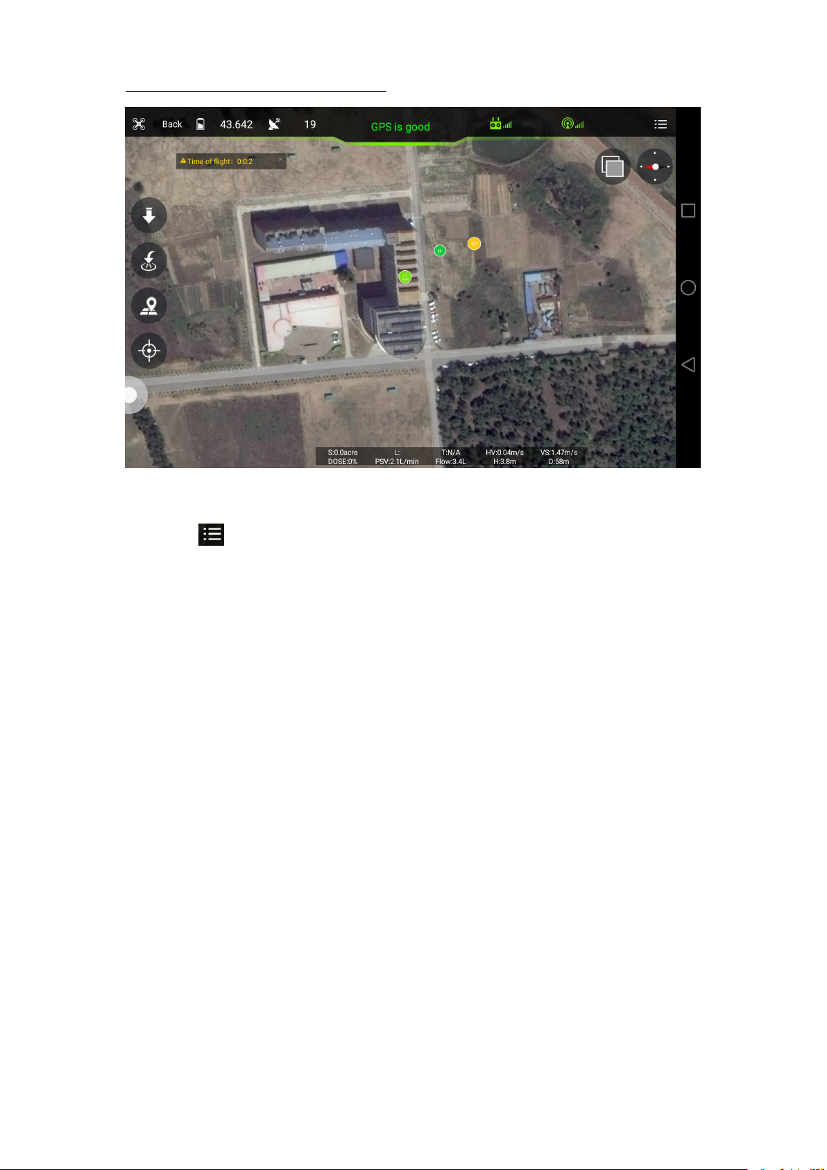
After connection,app will be as followings,see figure 5-4
Page 30
Copyright © 2017 TTAAll Rights Reserved. Appendix Implication of indicator light
29
5-4
5.2.1 Remote controller calibration
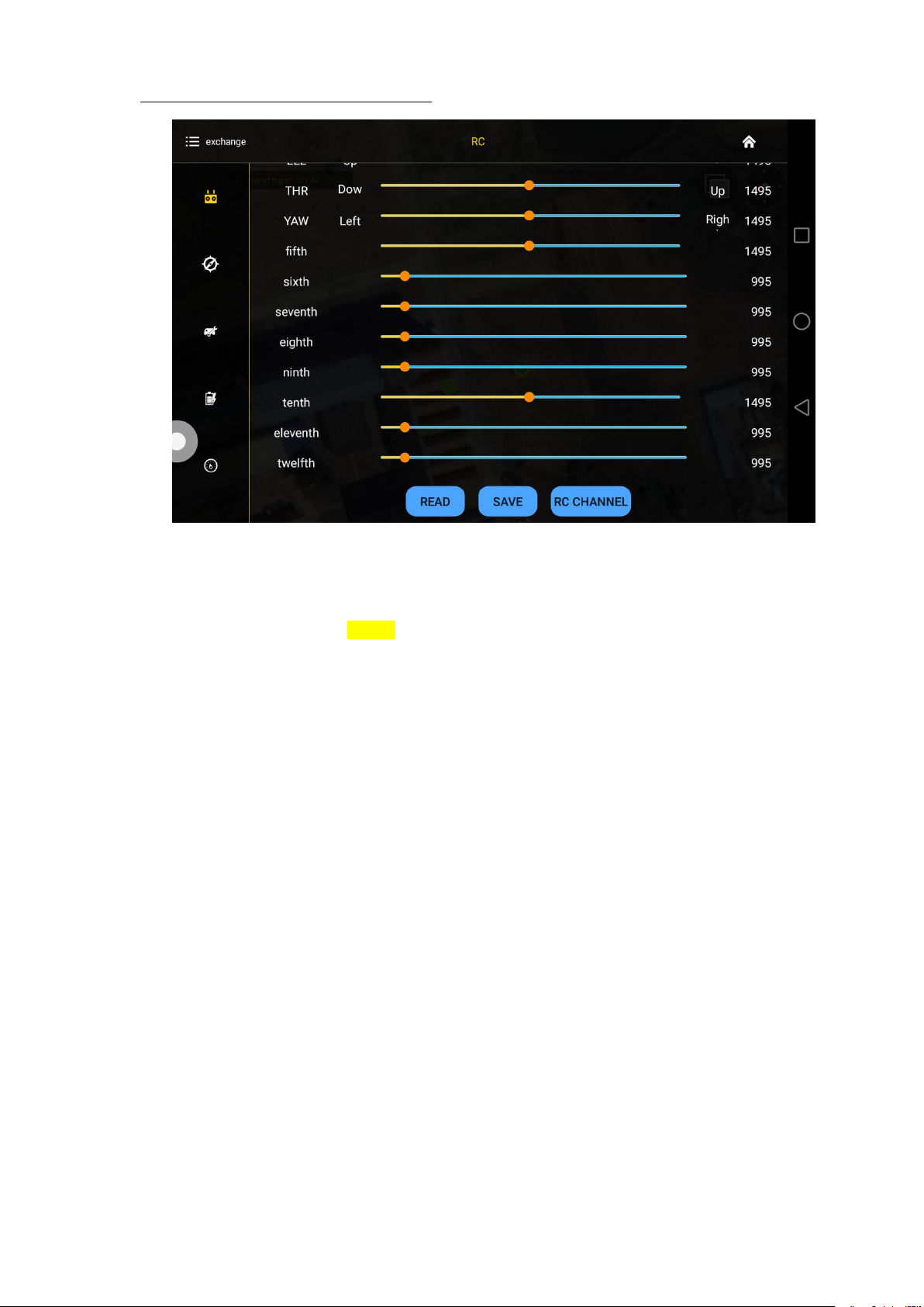
Click label at up right corner to enter into parameters adjustment.
Remote controller calibration:click the button READ to get the data,see the following
figure
Page 31
Copyright © 2017 TTAAll Rights Reserved. Appendix Implication of indicator light
30
1) Start to calibrate:connect copter with GCS,click RC CHANNEL,move the stick to
2) Stop calibration:click Finish after calibration. Then channel status could be
3) Normal or reverse setting of remote controller is set to check whether it’s right or
5.2.2 IMU calibration
maximum and minimum position 4 to 5 times.
checked.
wrong.
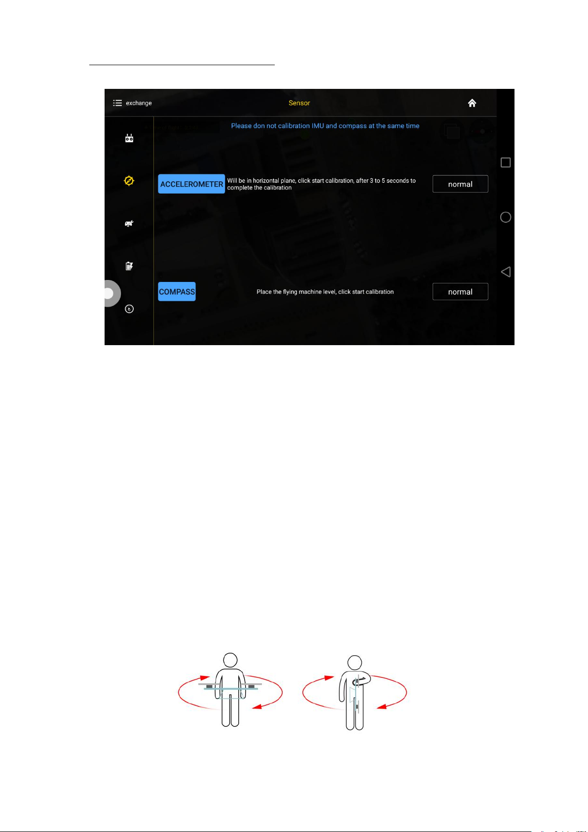
Leave the copter in a horizontal position,click the button ACCELEROMETER,LED will
flash in red,green,yellow alternately,LED green means successful calibration,data will be
stored by restart.
Page 32
Copyright © 2017 TTAAll Rights Reserved. Appendix Implication of indicator light
31
5.2.3 Compass calibration
Calibration order
Two kinds of method of compass calibration:
1) Click the button COMPASS to enter into calibration status.
2) Switch switch SA back and forth more than 4 times to enter into calibration status.
Calibration Step
1) Confirm GCS communication well, compass installation correct and copter outside.
2) Clicking calibration, yellow LED of copter is on, hold and keep copter rotating
clockwise and slowly, leave copter head to the ground when green led is on, rotate
copter clockwise and slowly till LED flash in red,green and yellow alternately.
Page 33
Copyright © 2017 TTAAll Rights Reserved. Appendix Implication of indicator light
32
3) After vertical calibration,calibration mode will be exited automatically and LED will
flash normally if successful, LED will keep red for 3 seconds if fails and recalibration
4) Please power again after successful calibration.
Attention:
1) Compass should be done after changing flying area.
2) Calibration should be done in outdoor,wild and far away from high tension line tower
3) Keep horizontal and vertical during the slow calibration.
4) Clockwise is the only direction.
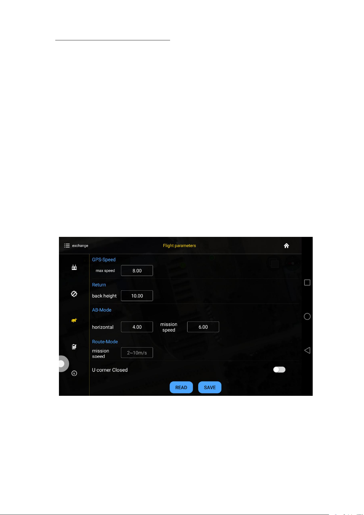
5.2.4 Flying parameters adjustment
should be done.
which is easy influenced by magnetic interference.
Click the button READ to obtain the current flying parameters,click button SAVE to save
the parameters.
Page 34
Copyright © 2017 TTAAll Rights Reserved. Appendix Implication of indicator light
33
The default number of back landing height is 20 meters,AB swath is 4 meters,route speed
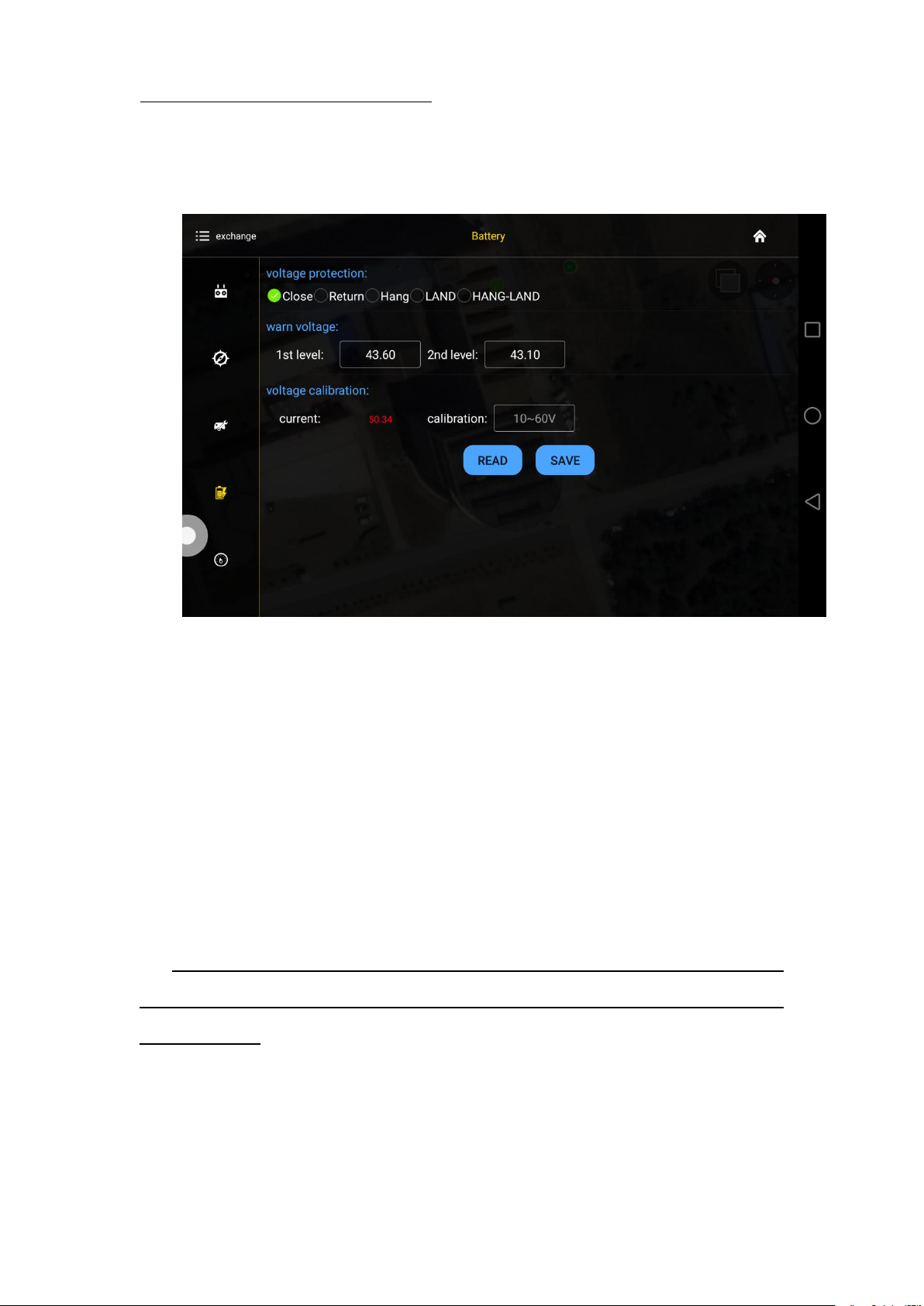
5.2.5 Low voltage protection
is 5m/s.
5.2.5.1 Low voltage protection settings
Five voltage protection has been provided:close,return to home point,hovering,auto
landing,hovering and then landing. User could choose the one suitable.The default is
auto landing.
5.2.5.2 Alarm voltage settings
Settings of first alarm and second alarm.It’s recommended to 43.6V for the first
alarm and 43.1V for second alarm.
LED will flash yellow triple when get to the first alarm level;LED will flash rapidly when
get to the second alarm level,copter will react as the low voltage settings,such as return to
home or landing.
Page 35
Copyright © 2017 TTAAll Rights Reserved. Appendix Implication of indicator light
34
5.2.5.3 Voltage calibration settings
Flight controller voltage sensor need to be calibrated if flight controller voltage sensor
result is different from real voltage.Real battery voltage should be filled in measured
voltage,flight controller voltage will be calibrated by clicking save. It’s unnecessary to set
by user as calibration has been done before delivery.
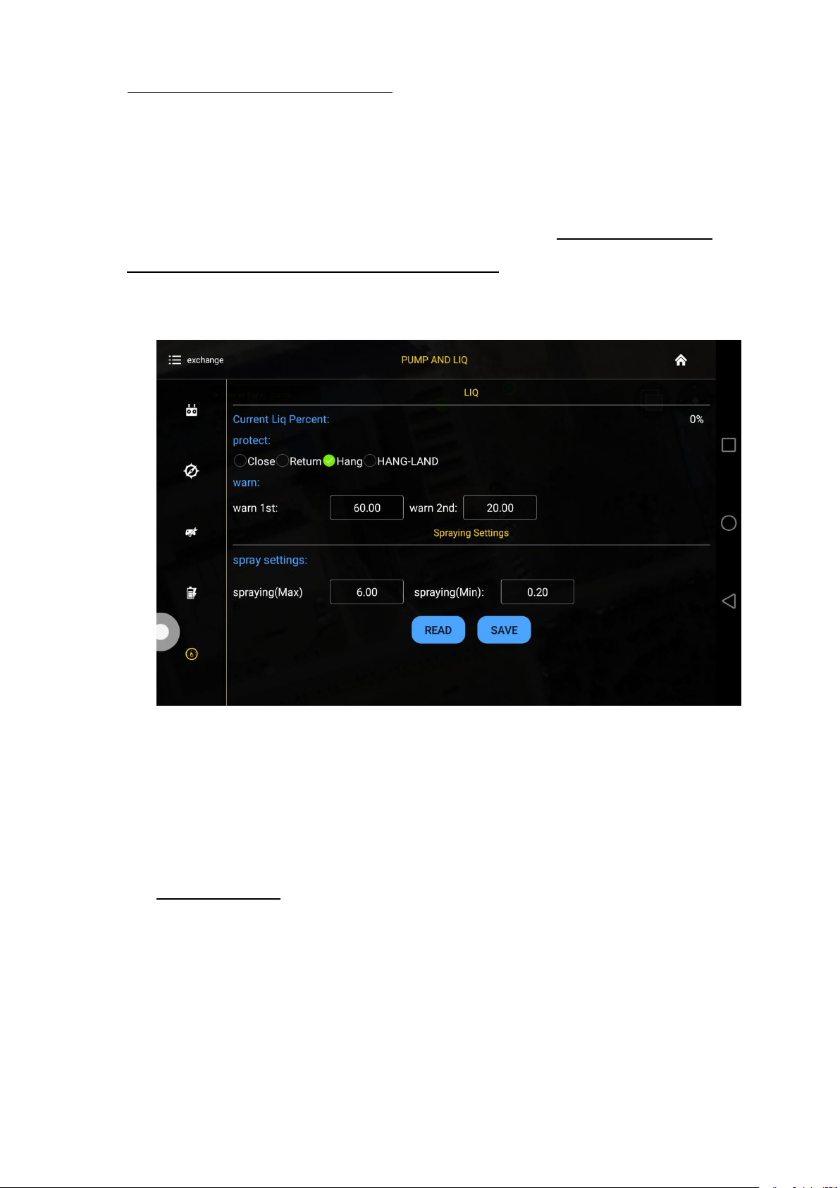
5.2.5.4 Pump and liquid level sensor settings
5.2.5.5 Tank empty reaction
The following reaction could be set:close the pump,return to home
point,hovering,hovering and then landing.The default is close the pump,which means only
LED flash as alarm.
Spraying settings
Combination control of the pump,max flow rate match to max flying speed. The
maximum default combination number is 6m/s,minimum default combination number is
0.2m/s.
Page 36
Copyright © 2017 TTAAll Rights Reserved. Appendix Implication of indicator light
35
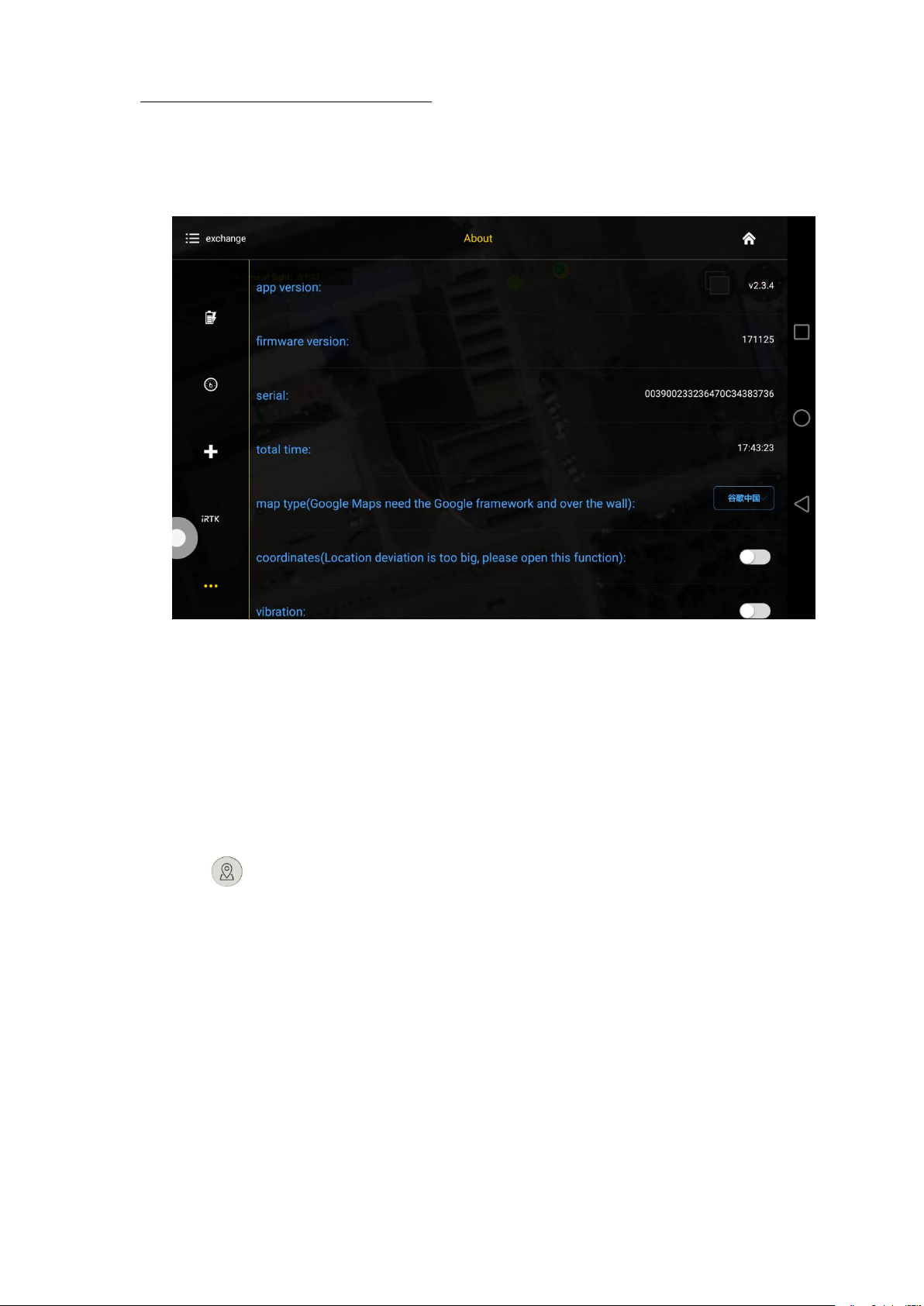
5.2.6 About interface
Open about interface,choose map type,choose Google map.Voice alarm could be
opened.
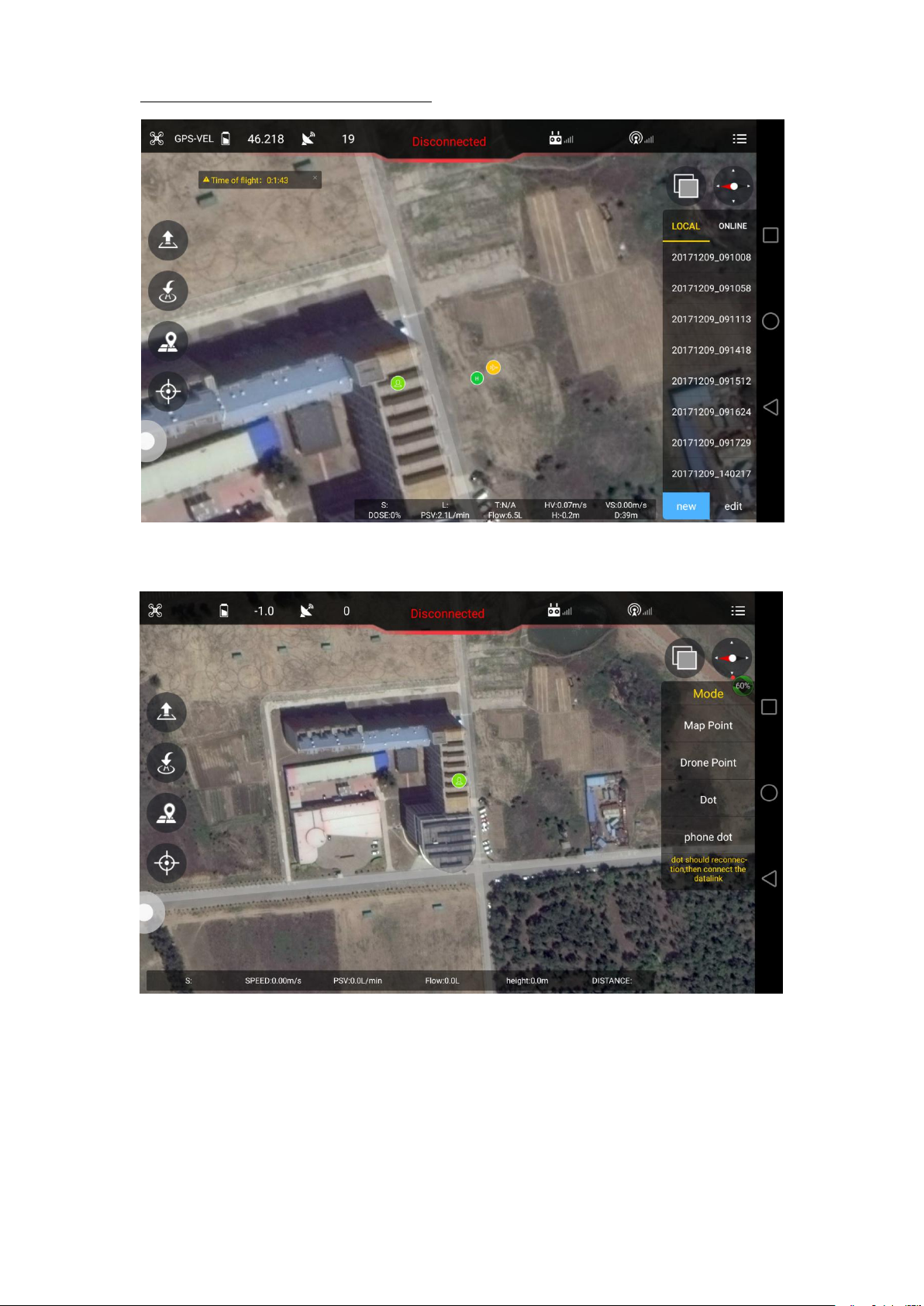
5.3 Route establish
Make point by map,make point by drone,make point by dot equipment,make point by
phone.Working area could be done by the followings:
1. Click to enter into route interface.
Page 37
Copyright © 2017 TTAAll Rights Reserved. Appendix Implication of indicator light
36
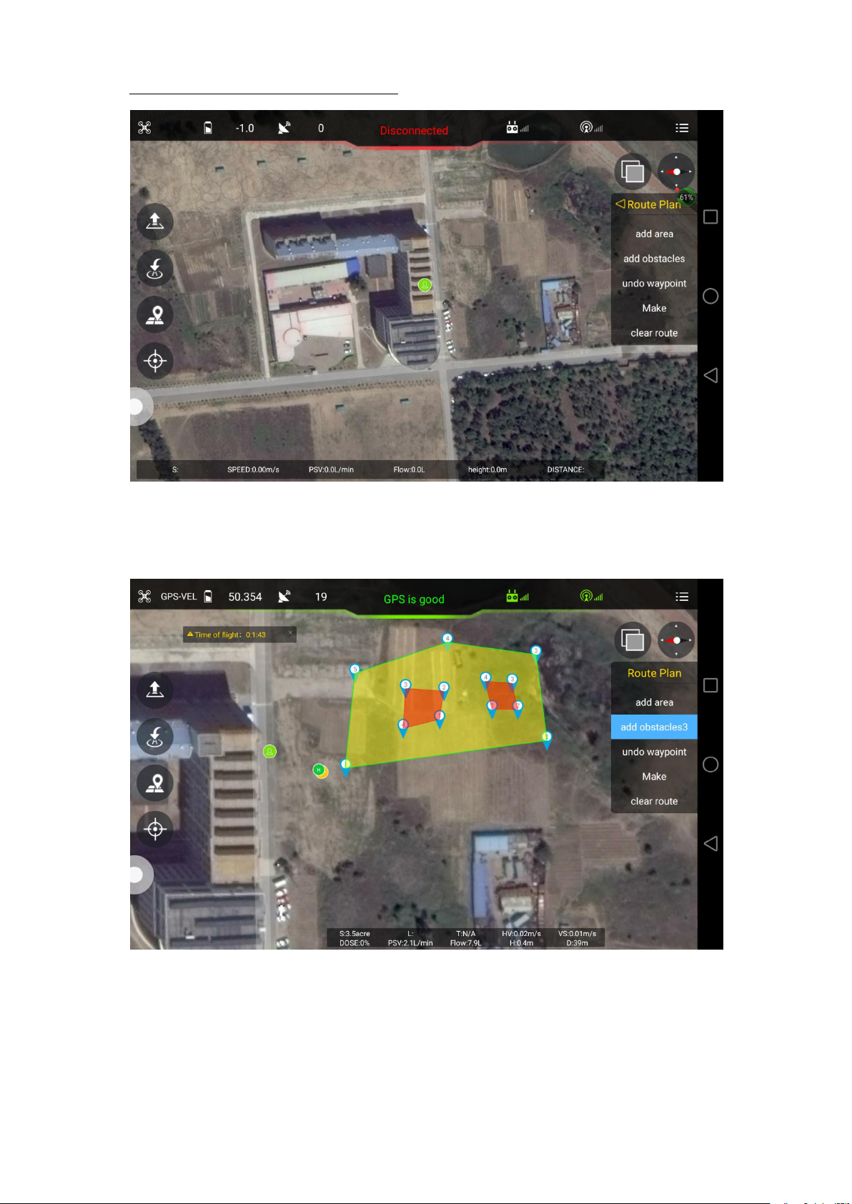
2. Click new to select point making type.
Making point from map(map point)
Page 38
Copyright © 2017 TTAAll Rights Reserved. Appendix Implication of indicator light
37
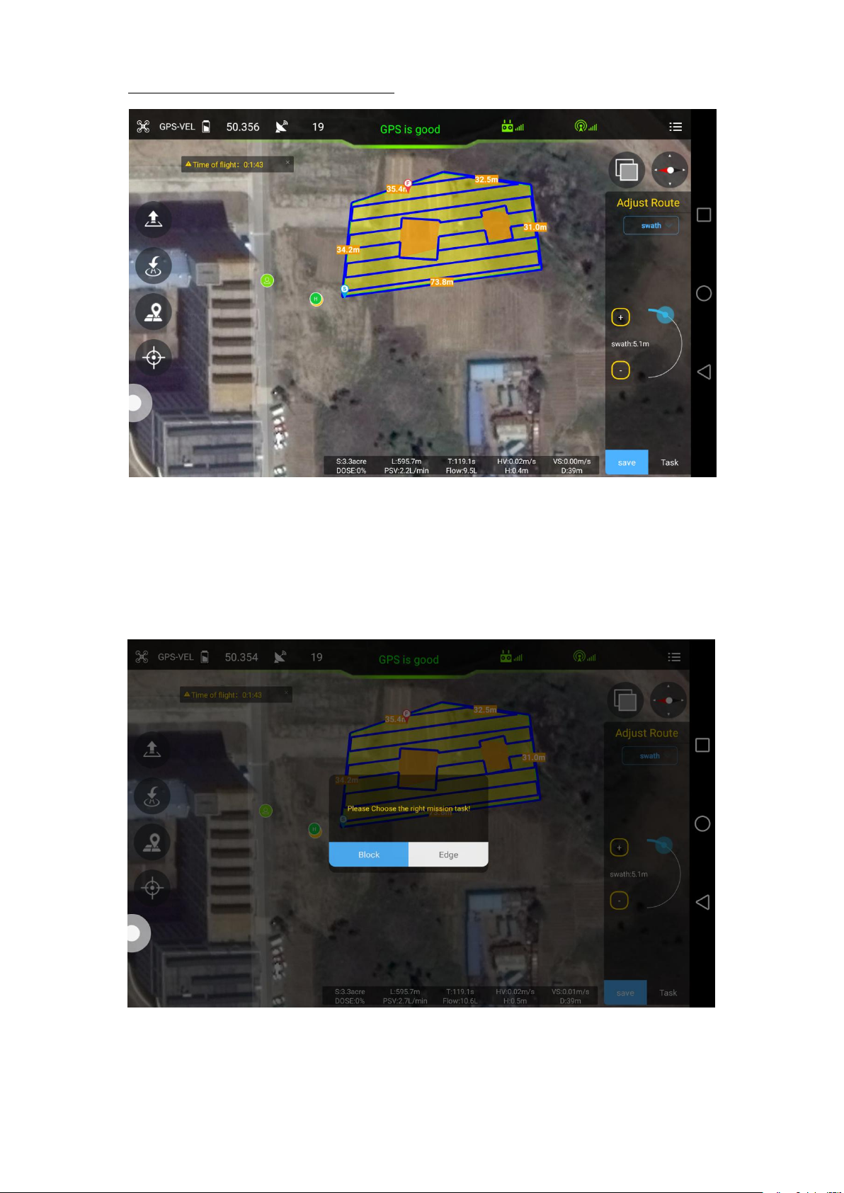
Select adding area to choose working area,obstacles could be added by clicking add
obstacles.
Rout can be made after area added.
Page 39
Copyright © 2017 TTAAll Rights Reserved. Appendix Implication of indicator light
38
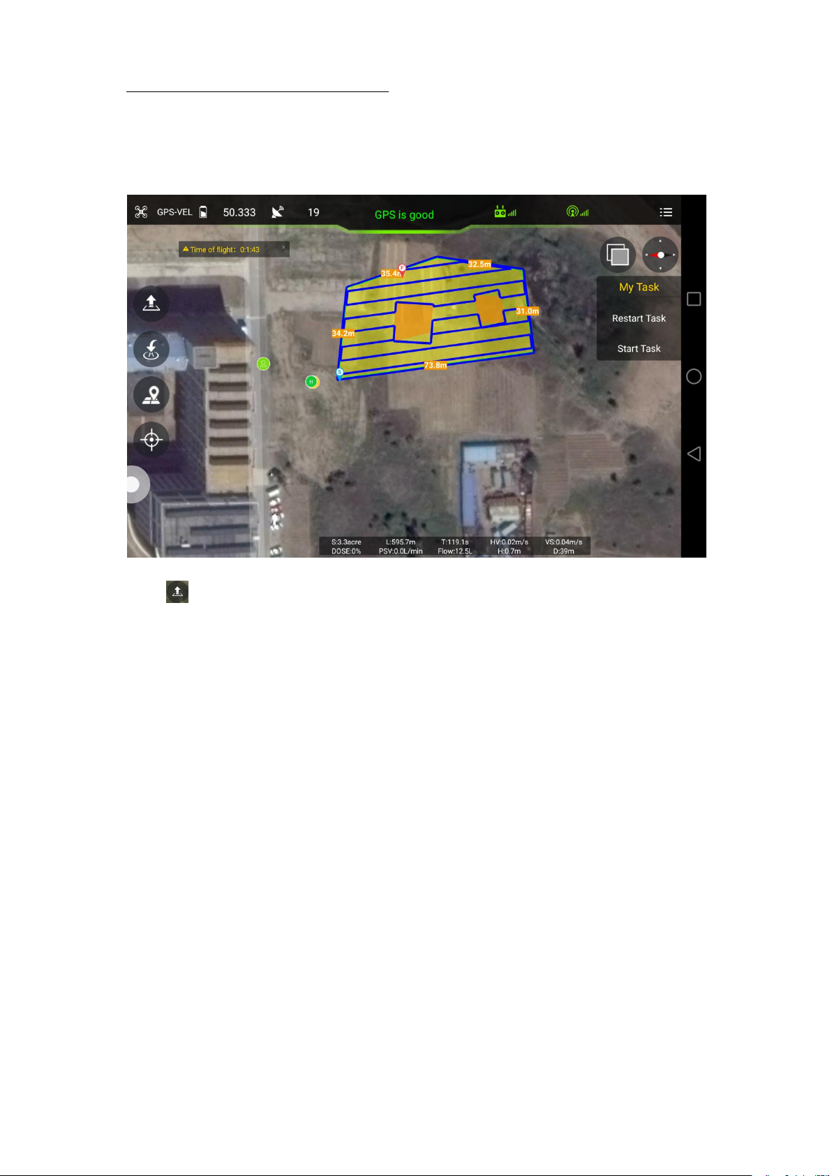
Swath(distance between each spraying),angle(angle of line),obstacle gap(distance
around the obstacle),target gap(distance between working area and
boundary),offset(offset of working area) in Adjust Route interface.Task could be saved
according to demands,and then upload it by selecting block(working area).
Page 40
Copyright © 2017 TTAAll Rights Reserved. Appendix Implication of indicator light
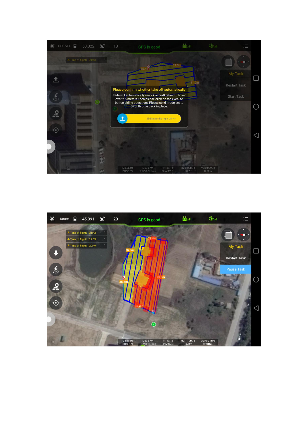
39
Click to take off from GCS or remote controller,click start task to execute the route.
Page 41
Copyright © 2017 TTAAll Rights Reserved. Appendix Implication of indicator light
40
Rudder and Throttle could be changed during flying,obstacles could also be
avoided by moving the Aileron stick.
Page 42

Copyright © 2017 TTAAll Rights Reserved. Appendix Implication of indicator light
41
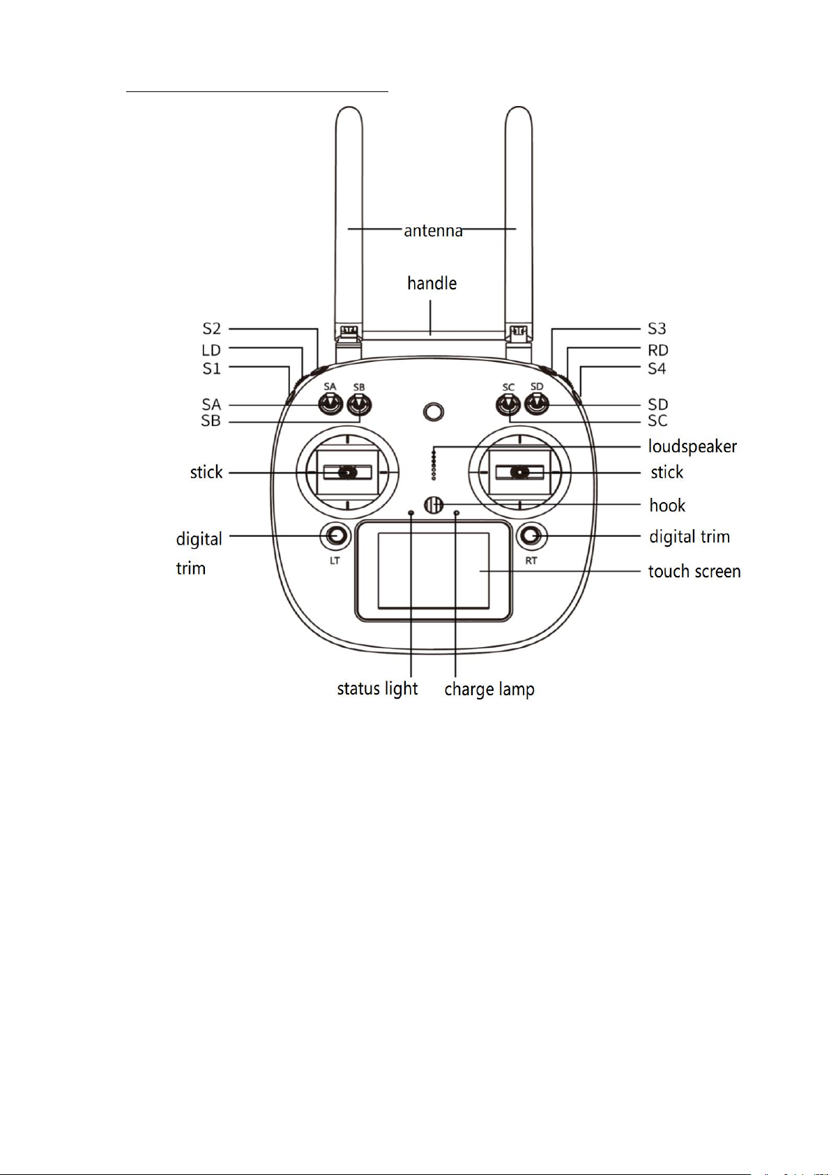
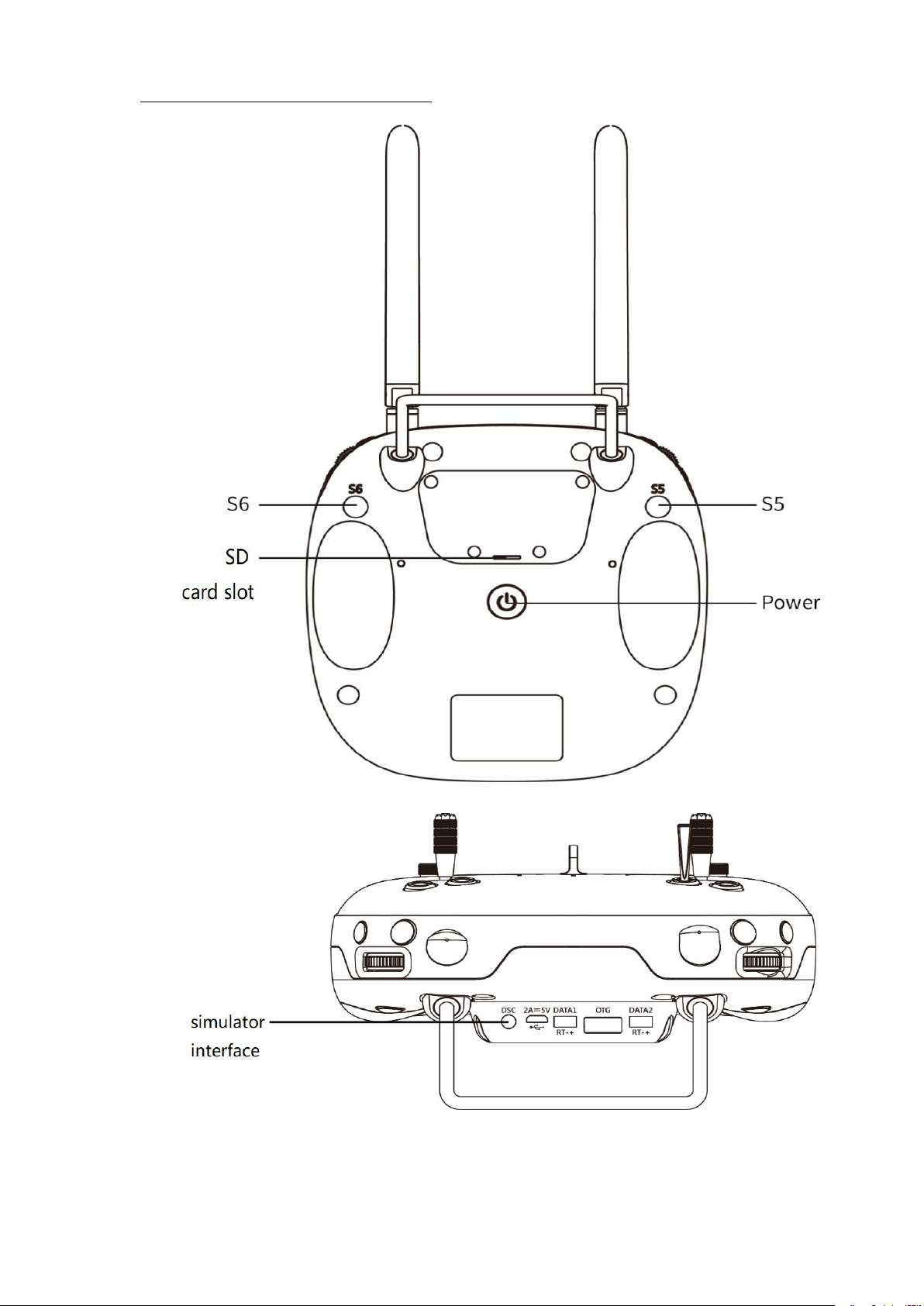
6. Remote Controller
Charger output more than 5V should not be used.
Remote controller charging current should be not more than 2A.
Any damaged,smoking or abnormal heating charger should not be used.
Charging should not be continued in condition of smoking,smelly,weeping.
Charging should not be in the area of baby playing.
Charging should not at temperature more than 60℃.
Page 43
Copyright © 2017 TTAAll Rights Reserved. Appendix Implication of indicator light
42
Page 44
Copyright © 2017 TTAAll Rights Reserved. Appendix Implication of indicator light
43
Page 45
Copyright © 2017 TTAAll Rights Reserved. Appendix Implication of indicator light
44
6.1 Function description
Channel
top
middle
bottom
SA: flight mode
Altitude mode
GPS mode
AB mode/automatic
SB: pump mode
OFF
combination
manual
SC: terrain following
OFF
/
ON
SD: AB recording
/
Recording Point A
Recording Point B
S3: pump
OFF
/
ON
S2: back landing
OFF
/
ON
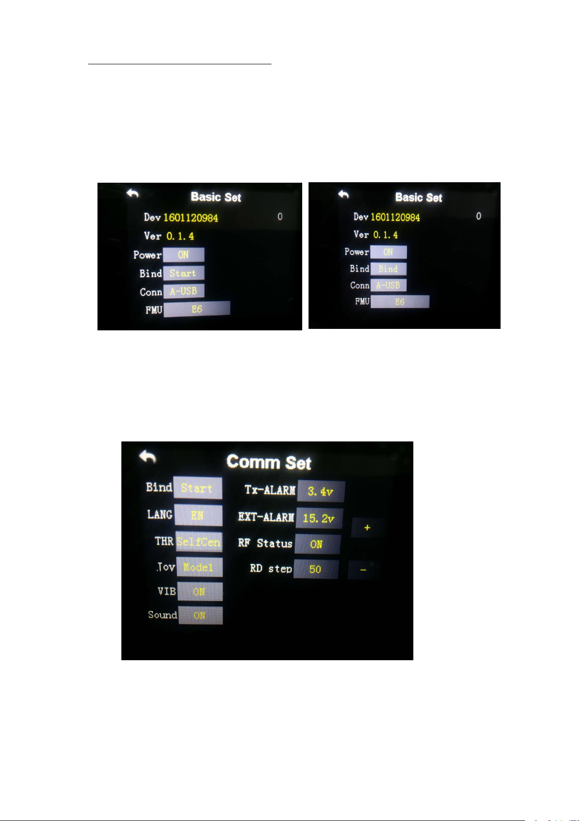
Bind by receiver
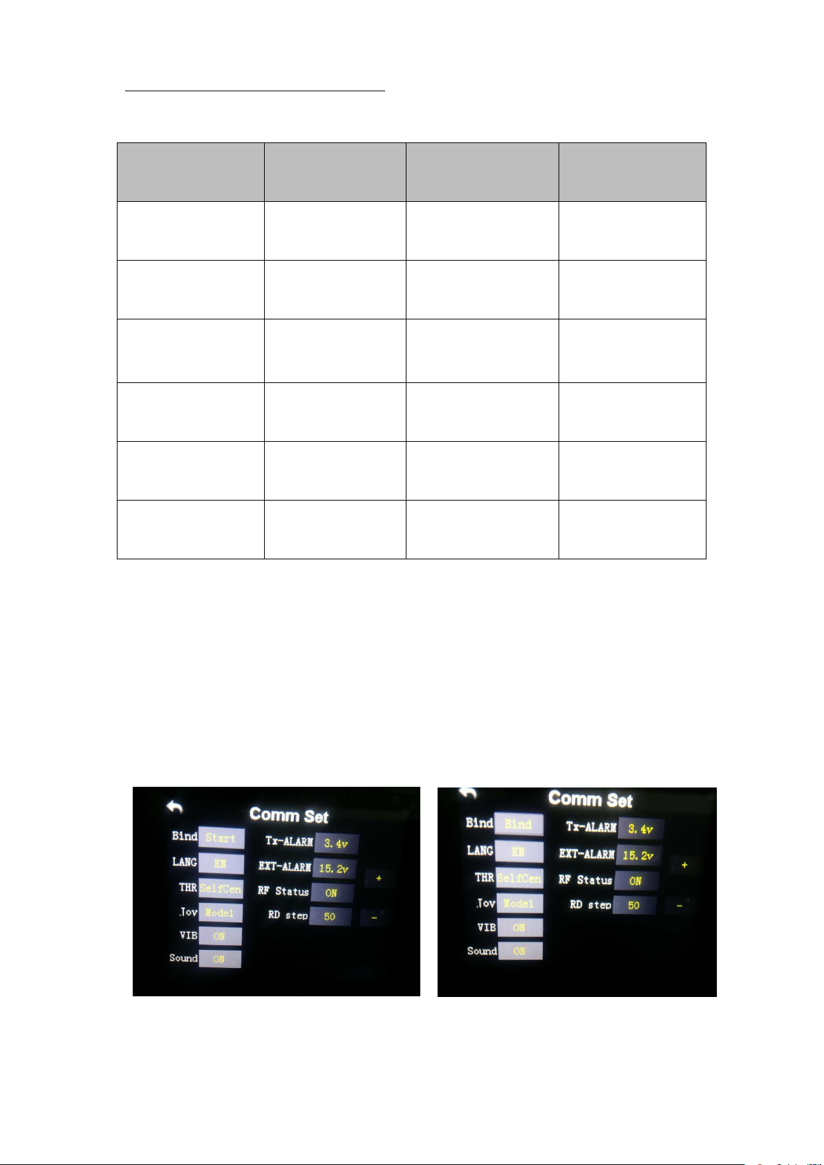
Select setting of main menu,click system setting--Comm Set,click Bind
start,then bind will be displayed.Power on the control system by power
bank,copter will enter into bind mode automatically if the last remote controller
signal could not be inspected after 5 seconds,finish will be displayed. Remote
controller need to be calibrated after bind.
6.2 Bind
Page 46
Copyright © 2017 TTAAll Rights Reserved. Appendix Implication of indicator light
45
Bind by datalink
Select setting of remote controller,click datalink--Basic Set,click Bind
Start,power on the control system by power bank,datalink will enter into bind
mode automatically if last remote controller can not be inspected after 5
seconds,finish will be displayed.
Remote controller joystick setting
1. Sel back to center remote controller:close alarm function.
2. Remote controller need to be set. Setting method:main menu--system
setting--click THR,choose SelCen.
Language could be set.
Page 47

Copyright © 2017 TTAAll Rights Reserved. Appendix Implication of indicator light
46
6.3 Remote controller antenna direction
7. Function Control
Flight
mode
Instruction
Operate
Condition
Altitude
mode
Horizontal
stabilization,yaw
locked,fixed altitude
By transmitter
GPS satellite
enough, LED does
not flash red
GPS mode
Fixed horizontal
point,yaw locked,fixed
altitude
Transmitter
operation/empty tank
reaction/others
GPS satellites
enough,LED does not
flash red
AB mode
Copter will fly and
spray along with AB point
Record point A
and B and switch to
AB mode,choose left
or right for roll
GPS satellites
enough, LED does
not flash red
Remote controller antenna should straight up when normal operation.
6.4 How to change between mode 1 and mode 2
Please change in the position:System--Comm Setting--Joy
7.1 Flight Mode
Page 48
Copyright © 2017 TTAAll Rights Reserved. Appendix Implication of indicator light
47
7.2 AB Mode
Return
mode
Copter will fly back
home point
automatically,flying back
tail to home point and
then descend slowly, it
could be controlled after
arriving on the top of
home point except throttle
Press button
Home
continuously/empty
tank reaction/low
voltage
reaction/reaction of
losing transmitter
signal
GPS satellites
enough, LED does
not flash red
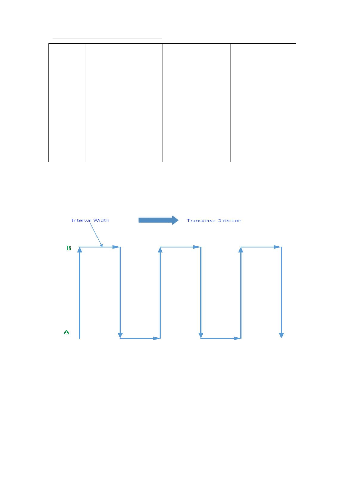
AB mode is a more simple efficient mode with fault tolerance to operate.The working
theory is above in the picture.Record the point A and B,the UAV will plan the flight line like
this.
1. Operate Steps:
Page 49

Copyright © 2017 TTAAll Rights Reserved. Appendix Implication of indicator light
48
1) Record the point A,switch the mode to GPS mode.Until the drone self-hovering
steadily,switch SD to ”Point A memorized”.After that,the LED flash yellow for 2
2) Record the point B,drive the drone to the position you want,be sure it is at least 10
3) Select the direction,switch SA (Flight mode) to AB mode, move the roll joystick to
4) AB Mode Correction
5) Shut Down and Quit
seconds.The controller have voice prompt.
meters away from point A.Until the drone self-hovering steadily,witch SD to ”Point B
memorized”.After that,the LED flash yellow for 2 seconds.The controller have voice
prompt.
select the roll direction.Move the joystick to the left limitation,the drone rolls to the left
side,move the joystick to the right limitation,the drone rolls to the right side.While the
drone doing AB point flight mode,the user can stop controlling the joystick.Make sure
that the water enough,the pump is under auto-controlled or manual-controlled.
①Altitude correction:Control the flight altitude by the throttle joystick, “up” for the
drone to rise, the “down” for the drone to set ;
②Correct the the rudder to control the direction;
③Fix point A:while the drone moving from point B to Point A,push up the pitch stick to
make point A 1m closer to point B,push down the pitch stick to make point A 1m
away from point B.
④Fix point B:while the drone moving from point A to Point B,push down the pitch stick
to make the point B away from point A,push down the pitch stick to make point B
1m closer to point A.
①When set the “no pesticide” action to self-hovering or return,in AB mode this
function still
Page 50

Copyright © 2017 TTAAll Rights Reserved. Appendix Implication of indicator light
49
works.
6) To return to the breakpoint, shut down the AB mode auto-controlled or manual-
1) Be sure to start AB mode within turning on the pump and agitation function working.
2) Be sure it is at least 10 meters away from point A to point be.
3) Every time recording point A and B,be sure to wait until the drone self-hovering
4) Without removing last AB point,can not set new AB point.
②When set the “low battery” action to return,in AB mode the this function still works.
③After the spraying work is done,AB mode can be shut down by switching into
altitude mode.
controlled. After filling the pesticide in the tank and taking off,switch SA (flight mode)to
AB mode directly ,the drone would return right to the breakpoint.
2. Remove Point A and B
Move stick SD (AB mode) for 4-5 times rapidly,LED alternately flash red green and
yellow,AB mode removed.Without removing last AB point,can not set new AB point.
3. Set the Interval Width
From the software->Flight parameters to set the spraying width and working speed
Attention:
steadily in GPS mode.
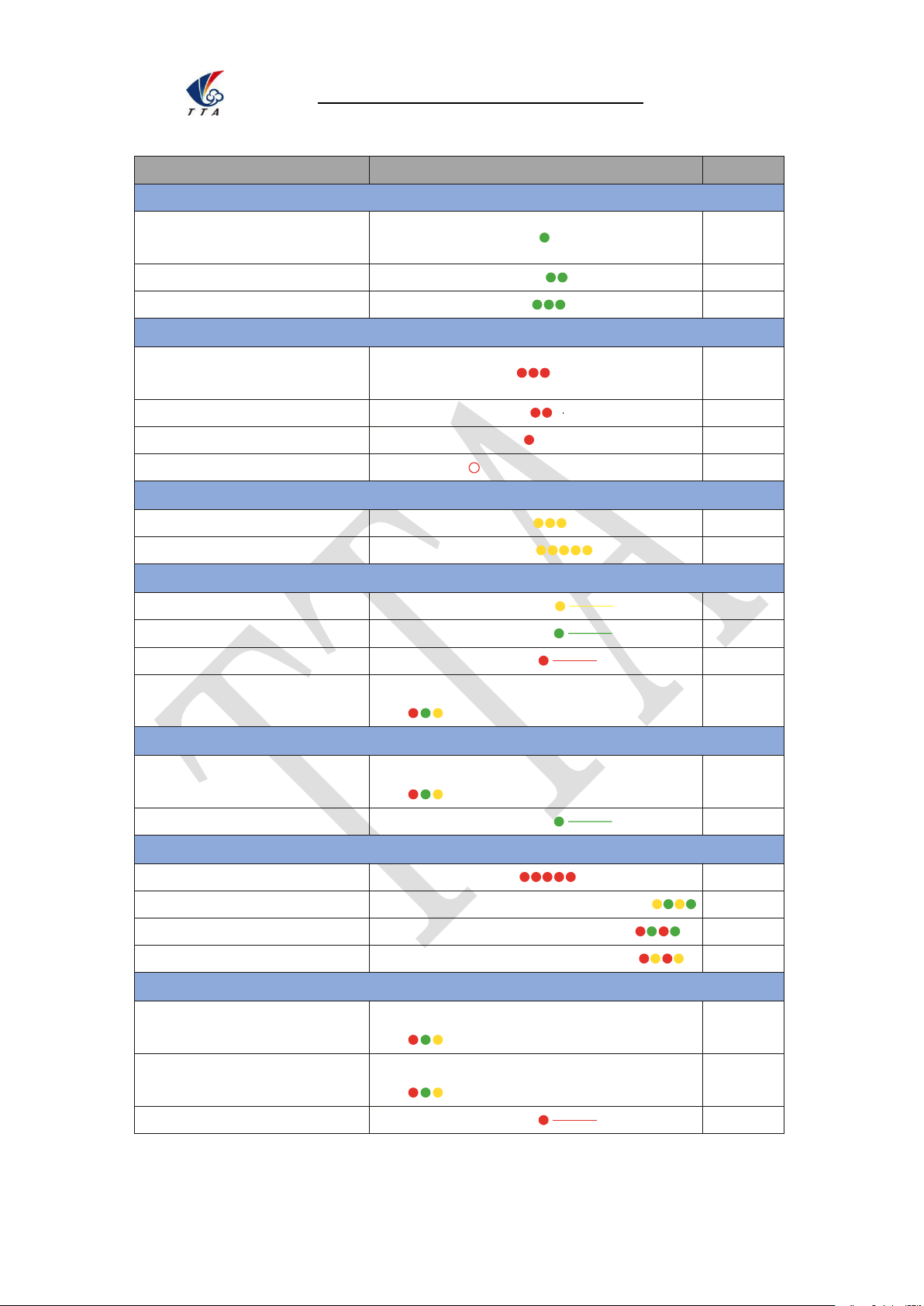
Appendix I Implication of Indicator Light
Page 51
Beijing TT Aviation Technology Co., Ltd.
Appendix I Implication of Indicator Light
50
Items
Indicator light
Priority
Flying Mode
Gyro
mode(stabilization,altitude)
Green light single flash
Low
GPS mode(angle,speed)
Green light double flash
Low
AB mode
Green light triple flash
Low
GPS
GPS unconnected/GPS
receive no satellite
Red light triple flash
Low
GPS bad signal
Red light double flash
Low
GPS general signal
Red light single flash
Low
GPS Good signal
Red light off
Low
Low Voltage Warn(alarm)
First alarm level
Yellow light triple flash
Low
Second alarm level
Yellow light quick flash
High
Compass Calibration
Horizontal calibration
Yellow light constant light
Middle
Vertical calibration
Green light constant light
Middle
Calibration failed
Red light constant light
Middle
Calibration succeed
Red,green and yellow light alternating
flash
Middle
Accelerator Calibration
Calibrating
Red,green and yellow light alternating
flash
Middle
Calibration succeed
Green light constant light
Middle
Error
Remote controller lose control
Red light quick flash
High
Compass interfered/error
Yellow and green light alternating flash
High
GPS lose satellite/error
Red and green light alternating flash
High
IMU over vibration/error
Red and yellow light alternating flash
High
Other Situations
Initializtion of power on
Red,green and yellow light alternating
flash
High
Unlock
Red,green and yellow light alternating
flash
High
Unlock failed
Red light constant light
High
Page 52
Beijing TT Aviation Technology Co., Ltd.
Appendix I Implication of Indicator Light
51
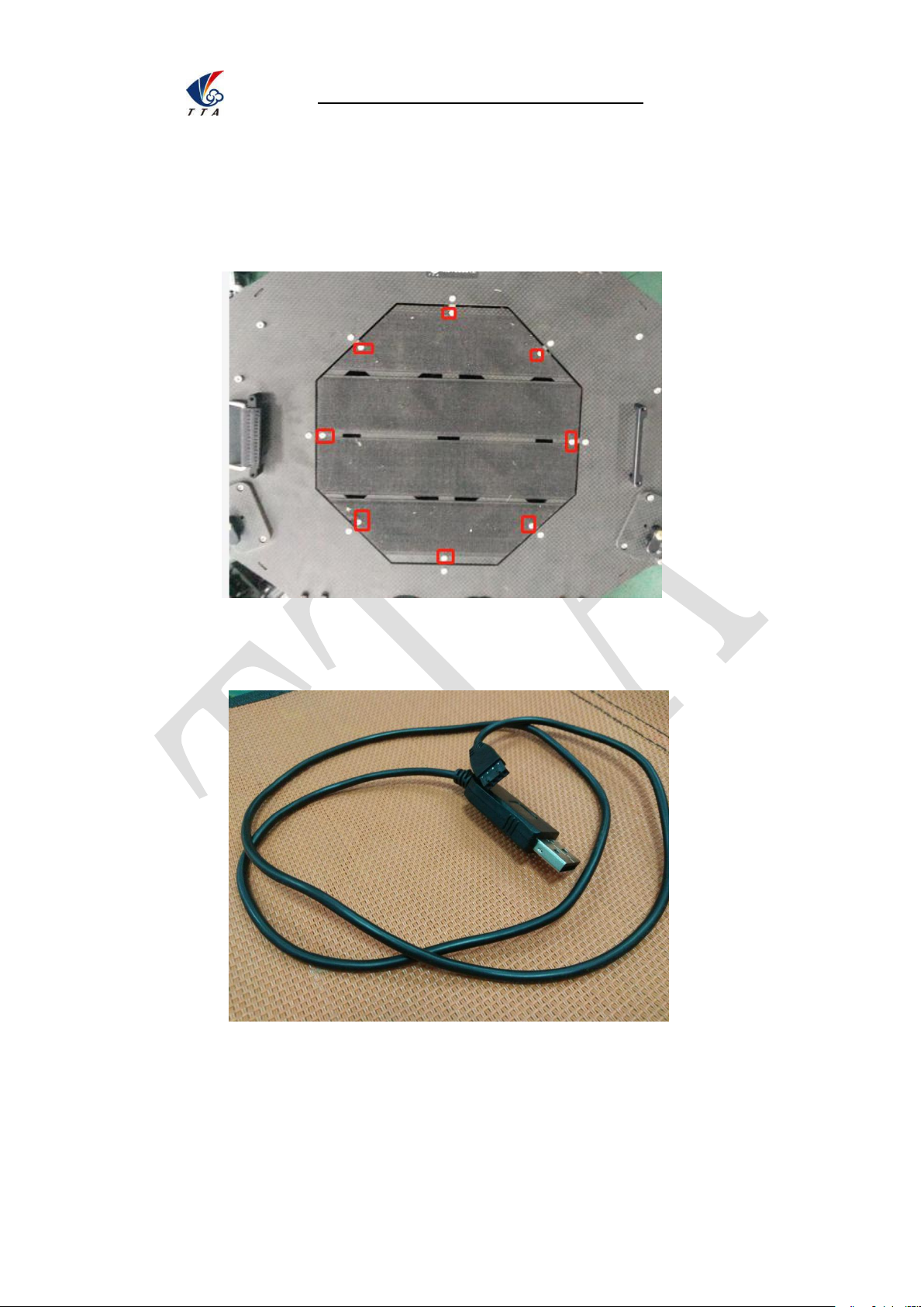
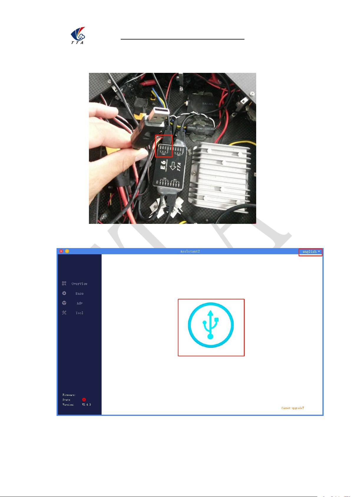
Appendix II How to connect copter to PC GCS
3 One connect to computer,another end connect to copter.Waiting for a moment(It takes
few minutes to install the driver for the first connection with a new computer),see figure 3:
1 Unscrew the 8 pieces of bolt and open the upper cover,see figure 1:
2 Find the computer connection cable from the attached bag,see figure 2:
Page 53
Beijing TT Aviation Technology Co., Ltd.
Appendix II How to connect copter to PC GCS
52
4 Open PC GCS,select the language you need.Click the connection button,see figure 4:
Page 54
Beijing TT Aviation Technology Co., Ltd.
Appendix II How to connect copter to PC GCS
53
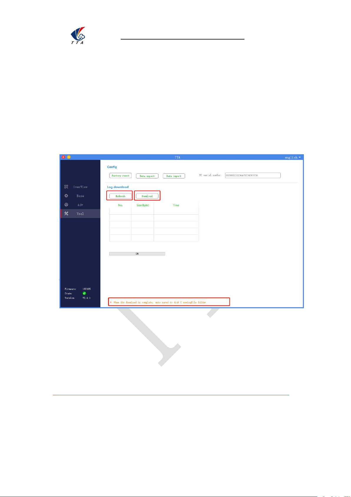
Appendix III How to download log from PC GCS
1.Open the PC GCS, select Tool menu
2.Click Refresh button
3.Click Download button
4. Log is saved in the position as the orange word
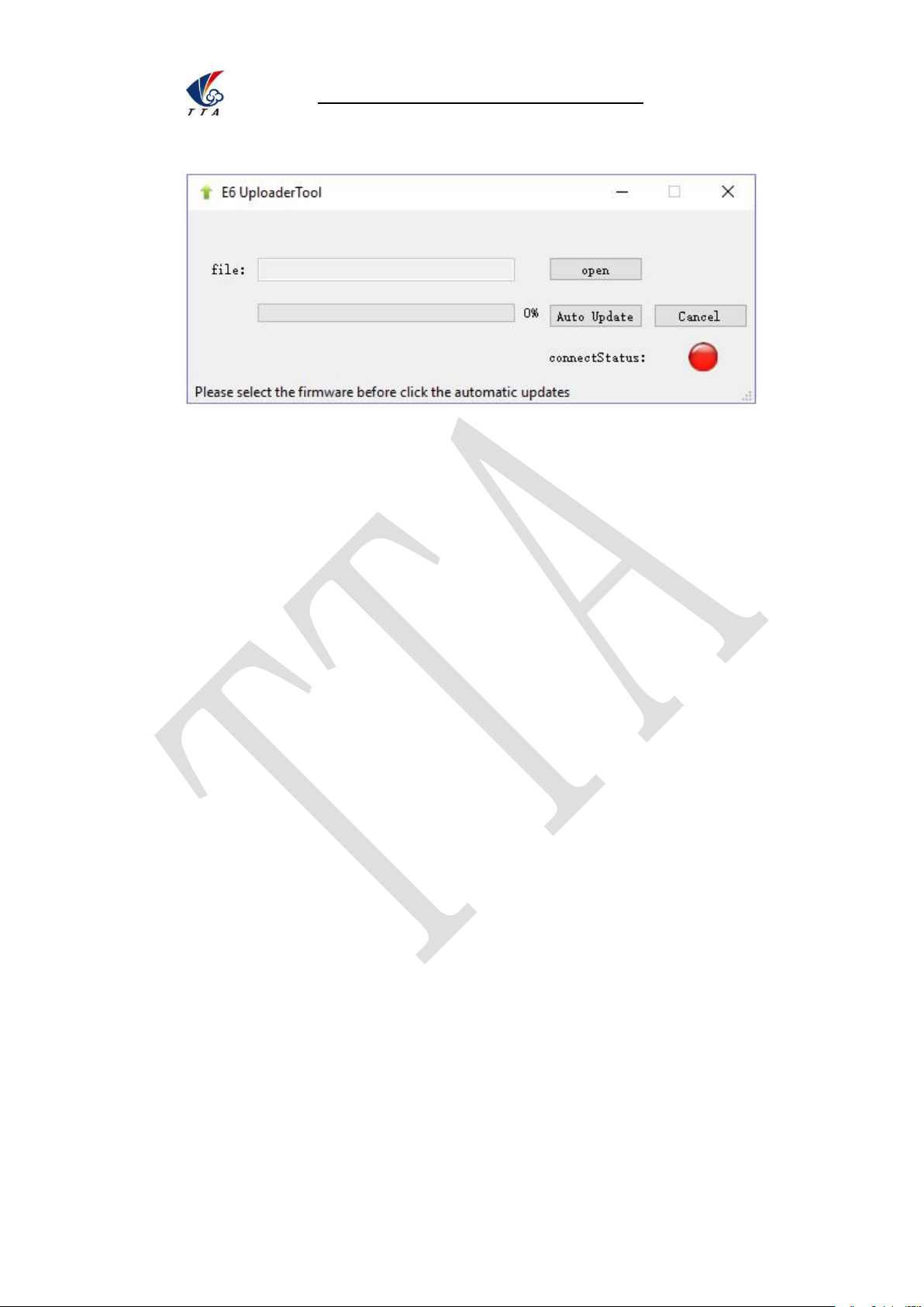
1 download the upgrading tool from the following address:
https://www.dropbox.com/sh/371k17zp8guv5y9/AAB8fUGjJ7zCN8qRF0Do8x57a?dl=0
2 Open the upgrading tool,see the following picture:
Appendix IV How to upgrade the firmware
Page 55
Beijing TT Aviation Technology Co., Ltd.
Appendix III How to download log from PC GCS
54
3 Click the button open,select the correct firmware.
4 Click the button Auto Update,then the circular indicator will turn to be green.LED of
copter usually is OFF during upgrading.
5 Waiting until the down left corner to 100%.The circular indicator will also turned to red
and LED will flash red yellow green to self inspection. Waiting for a moment,the led will
flash normally,then upgrading is finished.
6 Close the upgrading tool and disconnect the upgrade cable.
Disclaimer
1. To protect the legitimate rights and interests of users, please be sure to read our
instruction attached carefully before using product.Be sure to understand your
legitimate rights and interests, responsibilities and safety instructions; or it may cause
property damage, safety accident and hidden personal safety problem.Beijing TTA
reserves the right to update this document. Please be sure to in accordance with the
instructions and safety instructions operating this product.
2. The users use this product directly or indirectly, any violation of the law, TTA company
will not bear any responsibility.
3. This product is not suitable for under-18-year old and other who do not have full
capacity for civil conduct, please avoid these people use this product.While using this
product in public occasion please pay extra attention to operate.
4. Once you start using this product, deemed as you have read,recognized and
accepted the product specification, disclaimer and terms and conditions of all safety
instructions. It’s user's commitment to their own behavior and therefore is responsible
Page 56

Beijing TT Aviation Technology Co., Ltd.
Disclaimer
55
for all the consequences. Users promised to use this product only for legitimate
purposes, and agree to these terms and any others policies or guidelines TTA
company may develop .
5. In the process of using this product, please be sure to strictly obey the safety
instructions included in this document but not limited in it.For violations of the safety
information we have informed and cause any personal injury, accident, property
damage, legal disputes,conflicts of adverse events, and all others relevant
responsibilities,the loss should be borne by the users themselves, TTA company will
not bear any responsibility.
6. In the following situations, we do not provide any technical support and security
commitments:
A) through informal agents or improper access to this product units or individuals;
B) the unauthorized modification, debugging, and replacement parts products.
C) warranty card, serial number, or flight data lost;
D) due to personal error caused personal injury and property damage.
 Loading...