

Page 1
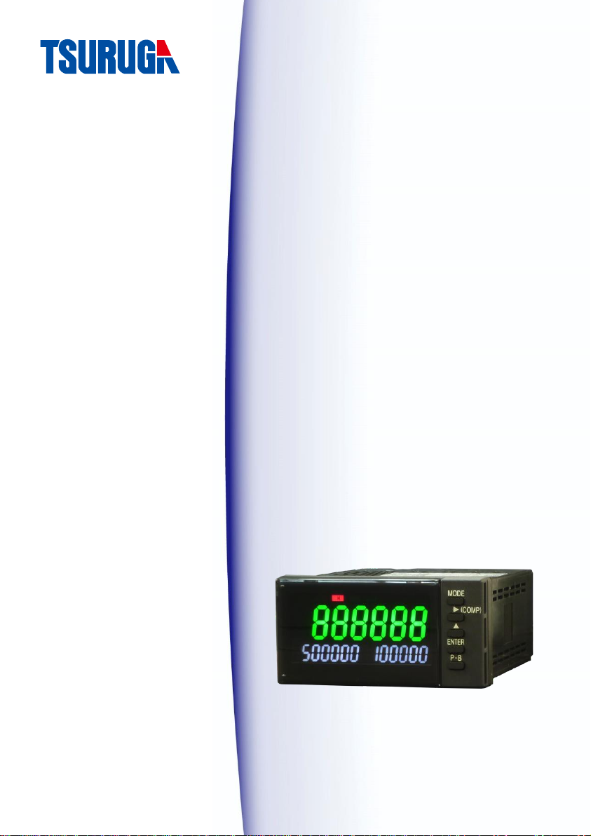
Tachometer
471C
Quick Manual
Page 2

Contents
Introduction ····················································· 1
About this booklet ········································································· 1
Precautions ·················································································· 1
Installation precautions ·································································· 2
Nomenclature ··················································· 3
Operation panel ············································································ 3
Rear panel ···················································································· 5
Installation ······················································· 6
Installation conditions ···································································· 6
Accessories··················································································· 6
Mounting method ·········································································· 7
Dismounting ················································································· 8
Wiring method ·············································································· 9
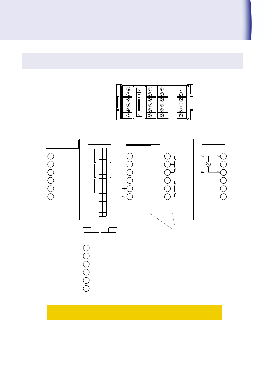
Terminal layout and explanation ···················································· 11
Usage of Function Code ··································· 16
Function code list ········································································ 16
Setting method of code No. ·························································· 17
Function setting method ······························································· 18
Usable Operation ············································ 22
Change comparison values of SV1 and SV2
Teaching function ········································································ 23
Adjustment of analog output (Option)
Restore to the factory setting
································································ 25
················································· 22
················································· 24
Specification ··················································· 26
Option Output ················································· 28
PhotoMOS compare output ··························································· 28
Analog output ············································································· 32
BCD output (Digital output) ·························································· 34
471C
Page 3

Introduction
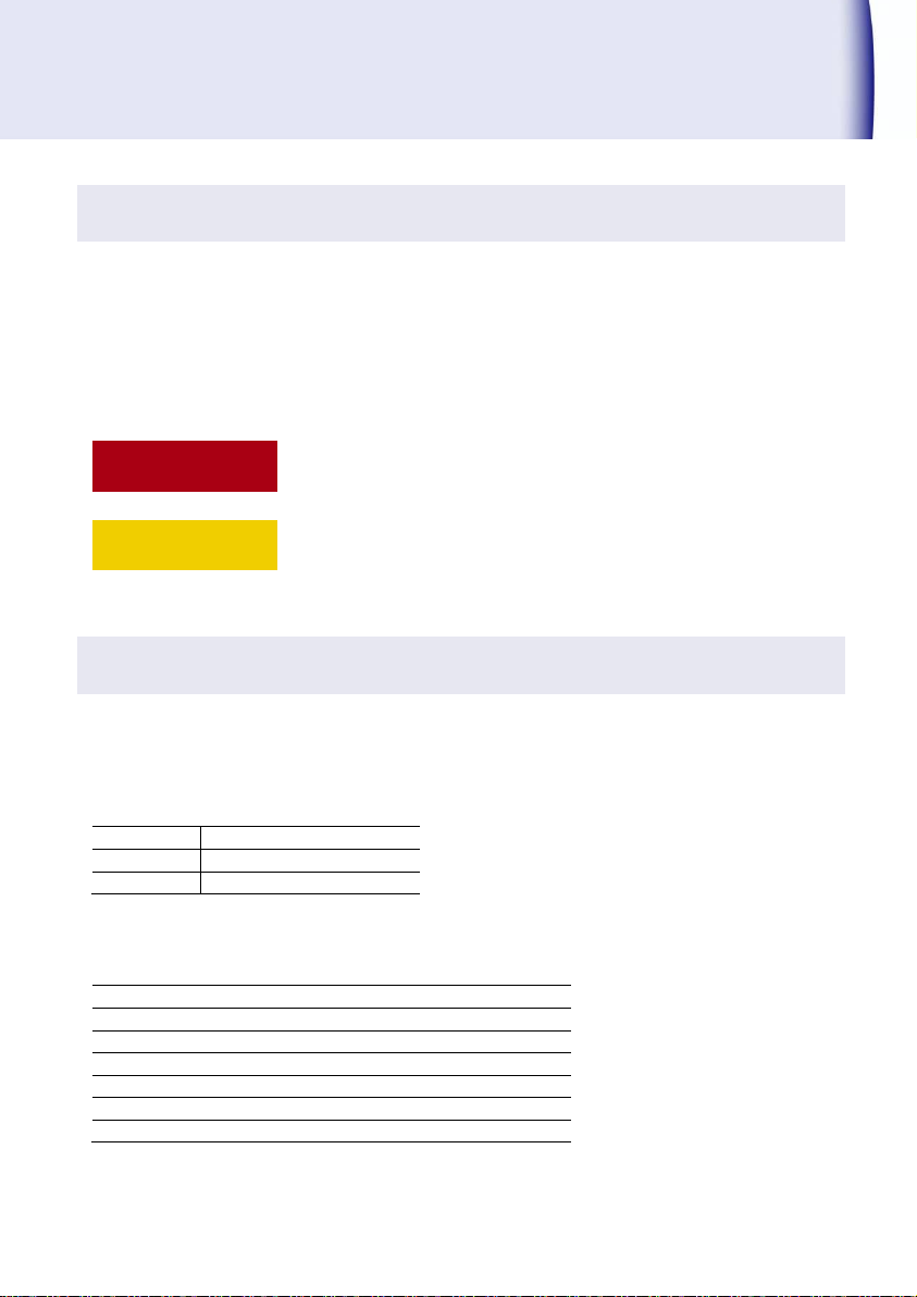
! Warning
This is the warning to avoid danger. Severe injure or fatal accident
may occur to the user in case the product is mishandled.
! Caution
This is the caution to avoid danger. Minor injury to the user or
physical obstacle may occur in case the product is mishandled.
This model is tachometer. Signal from rotor is displayed as rotation speed.
About this booklet
Thank you for purchasing our Tachometer 471C. Before use of the product, read this quick
manual carefully and thoroughly, and keep it available for routine reference.
If the product is not used in the specified way decided by manufacturer, the functions protected
and guaranteed by manufacturer may be lost.
The following symbol marks are used in this quick manual for the safety use of the product.
Precautions
For the safe use of this product, users must follow the following warning and caution.
! Warning
There is no power on-off switch on the model 471C. It immediately starts
to operate by connecting with power supply.
Never touch the terminals when power is ON. There may be risk of
electric shock.
! Caution
The rated data for warm up is specified for more than 15 minutes.
When the front panel or the case becomes dirty, wipe it with soft cloth. If
the dirt is difficult to remove, wipe it lightly with the soft moist cloth with
mild detergent diluted with water and finish by wiping with a dry cloth.
Do not use organic solvent like benzene or paint thinner as they may
deform or discolor the surface of the case.
471C 1
Page 4

Introduction(contd.)
Installation precautions
For the safe use of this product, users must follow the following caution.
! Caution
If the product is installed inside the cabinet, provision for the proper heat
dissipation should be done to prevent the temperature exceeding more
than 50 ℃ inside the cabinet.
Do not mount the product narrow distance. The rise of temperature may
decrease the life of the product.
Do not use the products in the following places. It may be the cause of
damage or malfunction.
*Wet place (rain, water drops), direct sunlight
*Place having high temperature, humidity, dust and corrosive gases
*Place having excessive noise, waves, static electricity
*Place having lots of vibration and shock
Store the product in the specified temperature range between -20℃ to
65℃.
2 471C
Page 5
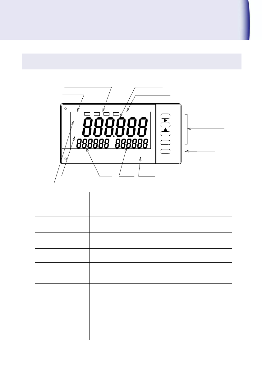
Nomenclature
No.
Name
Function
①
Display1
Process value (Current value) is displayed.
Red or green can be selected for display color.
②
Over
Light on when display1exceeds 999999.
Display color: Red
③
MEM
Light on when memory-enable set is ON (Code No.40).
Display color: Red
④
P・B
Light on when P.B is displayed.
Display color: Red
⑤
SV1
Either peak value or comparator value set by customer can
be displayed.
Display color: White
⑥
SV2
Either bottom value or comparator value set by customer
can be displayed.
Display color: White
⑦
Unit
Pasting position of Unit sticker
⑧
Comparative
display
The comparison status of the comparison output is
displayed.
⑨
SET Display
Light on during setting mode.
OVE R SET
ENTER
MODE
P・B
MEM
P・B
(COMP)
rpm
⑤SV1
⑥SV2
HH H L LL
① Display 1
④ P・B
⑦ Unit
⑧ Comparative display
⑨ SET Display
② Over
⑩ Setting ke y
⑪ P・B Key
③ Memory Dis play
Operation panel
471C 3
Page 6
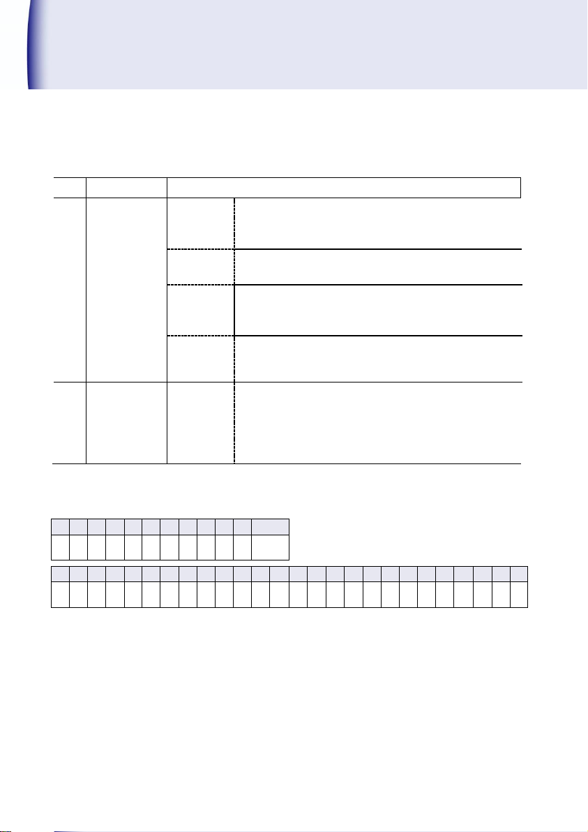
Nomenclature(contd.)
No.
Name
Function
⑩
Setting key
MODE
During measurement mode:Change to Setting mode,
Adjustment mode
During setting mode:Change to each code No.
▼(COMP)
During measurement mode: Set comparison value
During setting mode: Select the digit to change
▲
During measurement mode: Teaching function
(Except when switching to diagnosis mode)
During setting mode:Change of setting value
ENTER
During measurement mode:Invalid
During setting mode:Set value changed to saved
measurement mode
⑪
P・B key
P・B
During measurement mode:Reset Peak and Bottom
value
During setting mode: Setting mode changes to
measurement mode without
saving the set value.
0 1 2 3 4 5 6 7 8 9 DP
minus
0 1 2 3 4 5 6 7 8 9 .
-
A B C D E F G H I J K L M N O P Q R S T U V W X Y
Z
A B C D E F G H I J K L M N O P Q R S T U V W X Y
Z
Liquid Crystal Display
4 471C
Page 7
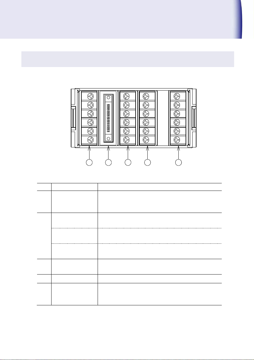
No.
Name
Function
⑫
Terminal A1 to A6
A1, A2:Sensor power supplies
A3, A4:Input terminals
A5, A6:Vacant terminals
⑬
BCD output
connector
Open collector NPN transistor output
Terminal RS-232C
B1 to B5:RS-232C communication
B6: Vacant terminal
Terminal RS-485
B1: + B2: - B4, B5: Terminal resistances
B3, B6: Vacant terminals
⑭
Terminal C1 to C6
C1 to C4: Input terminals of controlling comparator
C5, C6: Analog output terminals
⑮
Terminal D1 to D6
D1 to D6: HH, H, L and LL output terminals
⑯
Terminal E1 to E6
E1, E3: Power supply terminals
E5: Ground terminal
E2, E4, E6: Vacant terminals
1
2
3
4
5
6
A B C D E
12 13 14 15 16
Rear panel
※ ⑬, ⑭ and ⑮ are option specification
471C 5
Page 8
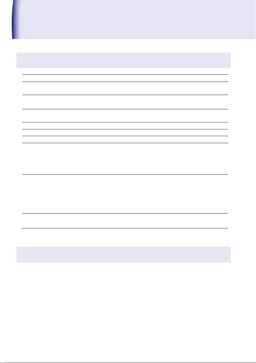
Installation
Power supply
AC100 to 240V 50/60Hz, DC24V
Voltage tolerance of
power supply
AC90 to 250V, DC24V±10%
Power consumption
During AC100V: Approx. 9VA, During AC200V: Approx. 12VA
During 24VA: Approx. 200mA
Operating ambient
temperature
0
to
50℃, 40
to
85%RH(No condensation)
Storage temperature
-20
to
65℃(No condensation)
Weight
Approx. 300g
Mounting method
Tighten from behind the panel with exclusive mounting bracket.
Insulation resistance
Measuring input terminals – External Case DC 500 V, More than 100 MΩ
Power supply terminal – External Case DC 500 V, More than 100 MΩ
Power supply terminal – Measuring input DC 500 V, More than 100 MΩ
Measuring input terminals – BCD output DC 500 V, More than 50 MΩ
Measuring input terminals – Analog output DC 500 V, More than 50 MΩ
Withstand voltage
Measuring input terminals – External Case AC 2000 V for one minute
Power supply terminal – External Case AC 2000 V for one minute
Power supply terminal – Measuring input AC1500 V for one minute
Measuring input terminals –
BCD output, RS-232C, RS-485 AC 500 V for one minute
Measuring input terminals – Analog output AC 500 V for one minute
Protective structure
Front operation unit IP65, Case part except front side IP20,
Terminal block IP00
Installation conditions
Accessories
Make sure that the following items are included with product supplied.
・471C main unit ・Bracket 2pcs. ・Waterproof packing
・Quick Manual (This booklet)
(For the model with RS-232C or RS-485, exclusive quick manual is included.)
・Unit Sticker
・Connector (2m with flat cable) (In case of BCD Output model)
6 471C
Page 9
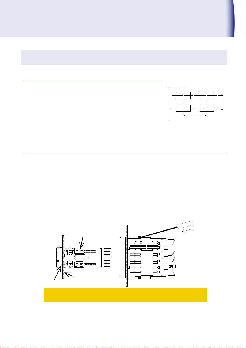
min.30
min.75
min.130
ECBA D
①
②
①
Push ②
Side view of bracket mounting
Top view of bracket mounting
Bracket
Panel to mount
Waterproof packing
Mounting method
Mounting pitch
Panel cutout dimensions: 92
Panel thickness: 0.6 to 3.5mm(Degree of protection IP65)
3.6 to 10mm(Degree of protection IP20)
If the material of the panel is aluminum, it may
be deformed due to its weak strength. So, it is
recommended to use the thickness of
aluminum panel sheet with at least 1.5mm.
Mounting pitch(Refer to the Right figure)
+0.8
0
× 45
+0.6
0
mm
Mounting method to panel
1 Insert the main unit fitted with the waterproof packing into the hole, from the panel
front, and insert the attached bracket to the ditch on both sides of the main unit.
Press the bracket as shown by arrow ① until the main unit is stably stays and fix the
bracket. Do not remove it as the packing acts as stopper too. Refer to the side view
drawing of the bracket mounting shown below.
2 To fix the main unit more firm, press the back part (center part) of the bracket
indicated by arrow ② by screwdriver, which enhances the stopper strength.
471C 7
When the bracket is pressed by minus screwdriver, press it to the
direction as shown in arrow ②.
The pressing of other part may cause the damage of bracket.
! Caution
Page 10
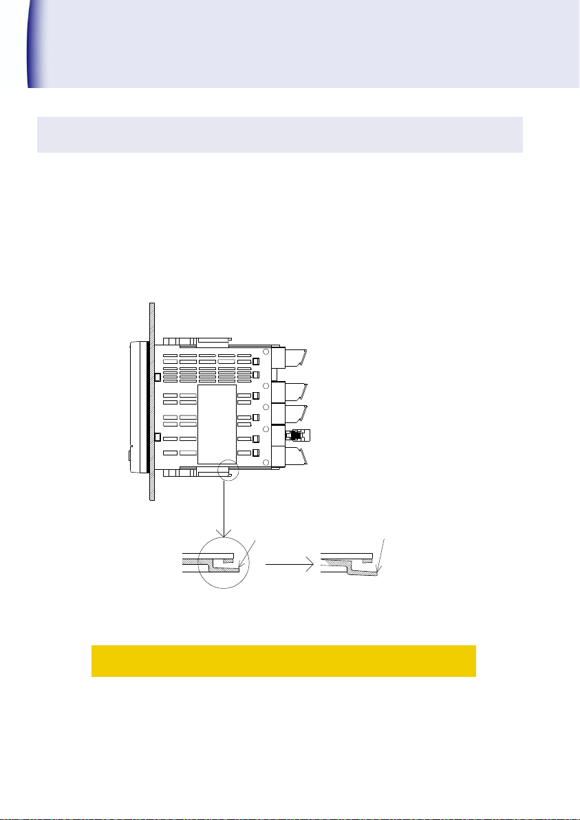
Installation(contd.)
ECBA D
Lever
Extend the lever about
1mm and releases the
lock
Enlarged view of
bracket inside
Bracket lock releasing
Dismounting
1 The lever lock of bracket can be released by extending the lever outward about 1 mm
by fingers as shown in figure below.
2 Keep extending the lever outward, slide the bracket backward of the main unit and
remove it from the ditch.
! Caution
The extension of the lever or the stress to it by metallic piece like
screwdriver for a long time may damage the lever.
8 471C
Page 11

Wiring method
Remove the terminal base cover of the rear side terminal and conduct the wiring. Make sure
that the terminal base cover is attached after wiring. If both options of comparison output and
analog output are used, first complete the wiring of the comparison output and then start the
wiring of analog output.
Notes for wiring
! Warning
To avoid an electrical shock, turn the power off when wiring.
Do not conduct wiring at moistened place or by wetted hands. There may
be risk of electric shock.
Do not touch the terminals when turning the power on. There may be risk
of electric shock.
! Caution
Power supply and load should be within the suitable range as prescribed
in specification. Negligence may cause the damage of products.
Power supply should reach the rated power within a second.
After the power is OFF, pause more than 10 seconds before the power ON
again.
Do not use the product with wrong wiring. It may be the cause of product
damage.
◆
Others caution during wiring
Always use input line and power line independently. If input line and power line are wired in
parallel, it may cause an in stability of the display.
When the auxiliary relay is operated by the relay output to run the electro- magnetic switch
or big size relay, take the noise preventive measures.
In case that the noise is frequently occurred, it will be effective to store the product in the
shielded housing or to insert the power source line filter or insulated transformer.
471C 9
Page 12
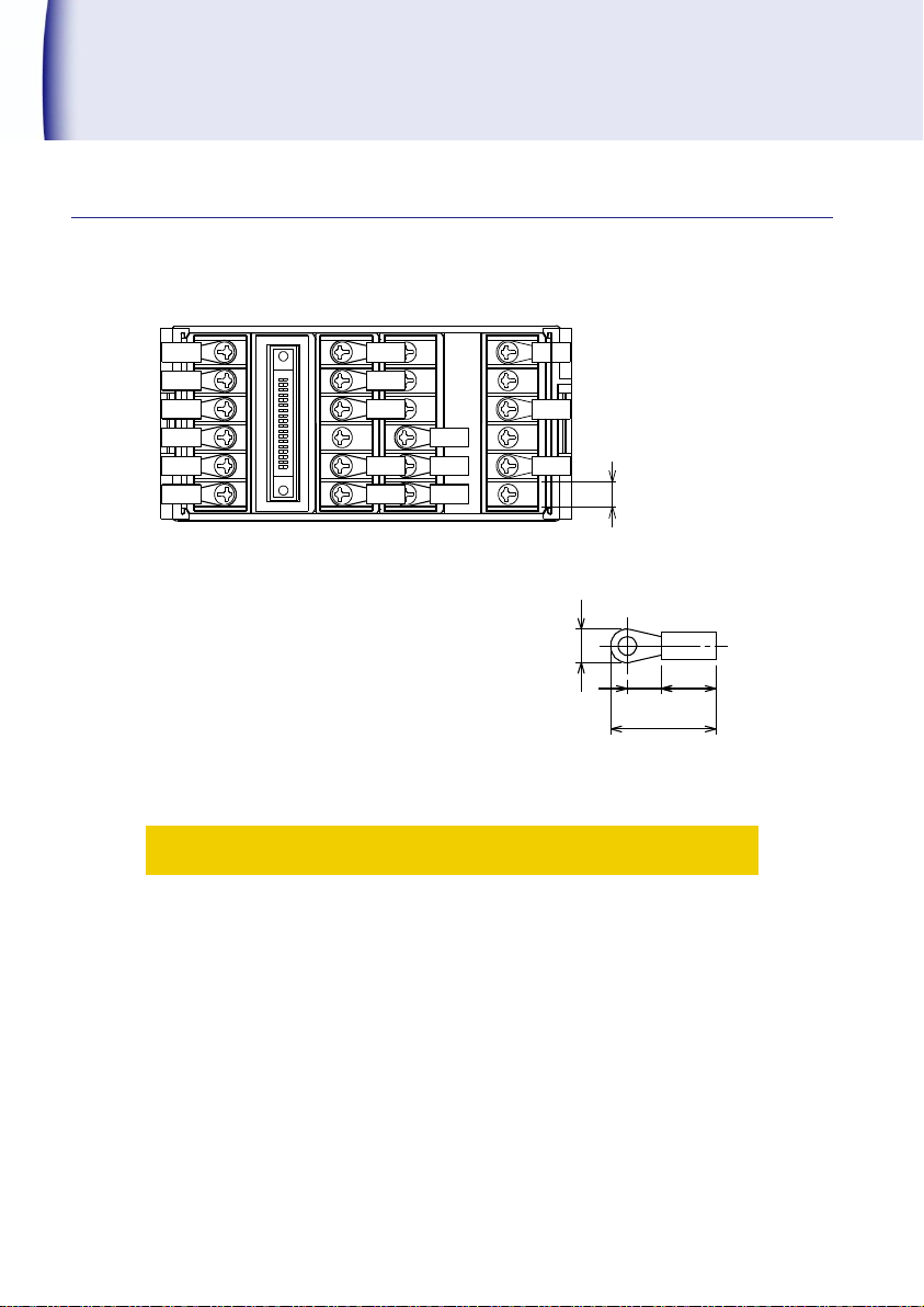
Installation(contd.)
Recommended crimp terminal:V1.25-FS3
(Made of Fuji Terminal Industry Co., Ltd)
Ext. diameter of covered cable:Max.φ3.3
Terminal screw:M3
Crimp terminal: Refer figure at the right
1
2
3
4
5
6
A
B C D E
6
18. 25
9.5
5.8 5
5.8
About the crimp terminal
Direction of crimp terminal
! Caution
For the column B (RS-232C and RS-485), column C and D terminal blocks,
apply just one crimp terminal per terminal location.
Do not wire the parallel connection, using two crimp terminals
(overlaying) at the same terminal location. It stresses the internal PCB
and may cause the failure or trouble. As for the A column and E column
terminal blocks, up to two crimp terminals per terminal location are
acceptable.
10 471C
Page 13
1
2
3
4
5
6
▲
A
B C D E
Term
NC
-
+
B6
B5
B4
B3
B2
B1
NCNC
SG
CS
RD
RS
SD
Term
1
2
3
4
5
6
7
8
9
10
11
12
13
14
15
16
17
18
4
2
8
1
4
2
8
1
4
2
8
1
4
2
8
1
4
2
8
1
4
2
8
1
10
10
10
10
10 10
E1
E2
E3
E4
E5
E6
N C
N C
AC100~24 0V
BCD_LATCH
SYNC
19
20
21
22
23
24
25
26
27
28
29
30
31
32
33
34
35
36
GND
DP1
DP2
DP3
DP4
D1
D2
D3
D4
D5
D6
HH
H
L
LL
0
1
2
3
4
5
POL
OUTPUT E NABLE
DATA COM
DATA COM
DATA COM
C1
C2
C3
C4
C5
C6
A1
A2
A3
A4
A5
A6
COM
NC
NC
SIG1
SIG2
OVER
H-COM
L-COM
SENSO R
DC24V
+
-
NC
M.COM
M.SEL1
M.SEL2
M.SEL4
Sensor po wer suppl y
BCD o utpu t
Analo g ou tput
Power supply
At option al RS-232 C output At option al RS-485 output
At option al BCD outp ut
At option al
analog ou tput
When ther e is no o ption,
it become s NC (Vac ant terminal).
A.OUT +
A.OUT -
B C D
a termina l block)
(B column i s
a termina l block)
(B column i s
EA
RS-48 5RS-23 2C
At option al
comparion output
Measuring i nput
Compariso n output( With selected mem ory
for compa rison)
NC: Non contact terminal
Do not use it.
NC: Non contact terminal
Do not use it.
NC: Non contact terminal
Do not use it.
Terminal layout and explanation
Rear side terminal
471C 11
・Replacement of the above terminal units by customers themselves is
prohibited because it may be the cause the damage of the product.
! Caution
Page 14
Installation(contd.)
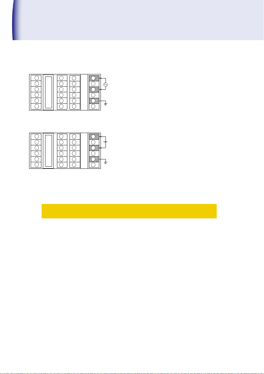
Connect the power supply at terminal No. E1-E3.
Power supply voltage is mentioned on the
terminal nameplate at the time of shipment.
○AC power supply
AC100 to 240V 50/60Hz
Permissible range AC 90 to 250V
○DC power supply
DC 24V
Permissible range DC24V±10%
1
2
3
4
5
6
A
B C D E
+
-
1
2
3
4
5
6
A
B C D E
GND for
power supply
GND for
power supply
AC power supply
DC power supply
Power supply connection
! Caution
Do not use the voltage out of permissible range. It may be the cause of
equipment damage.
Power on / off, power supply should reach up to rated voltage or shut
down within 1 second.
After the power is OFF, pause more than 10 seconds before the power ON
12 471C
again.
GND (ground) terminal
In case of frequent noise generation on the power source line, it is
effective to earth the ground terminal directly to the ground. If the
instrument is not affected by environmental noise, the grounding can be
omitted. In this case, take care for the ground terminal not to touch
other input terminals, as it is charged with neutral electric potential of
power source voltage.
Page 15
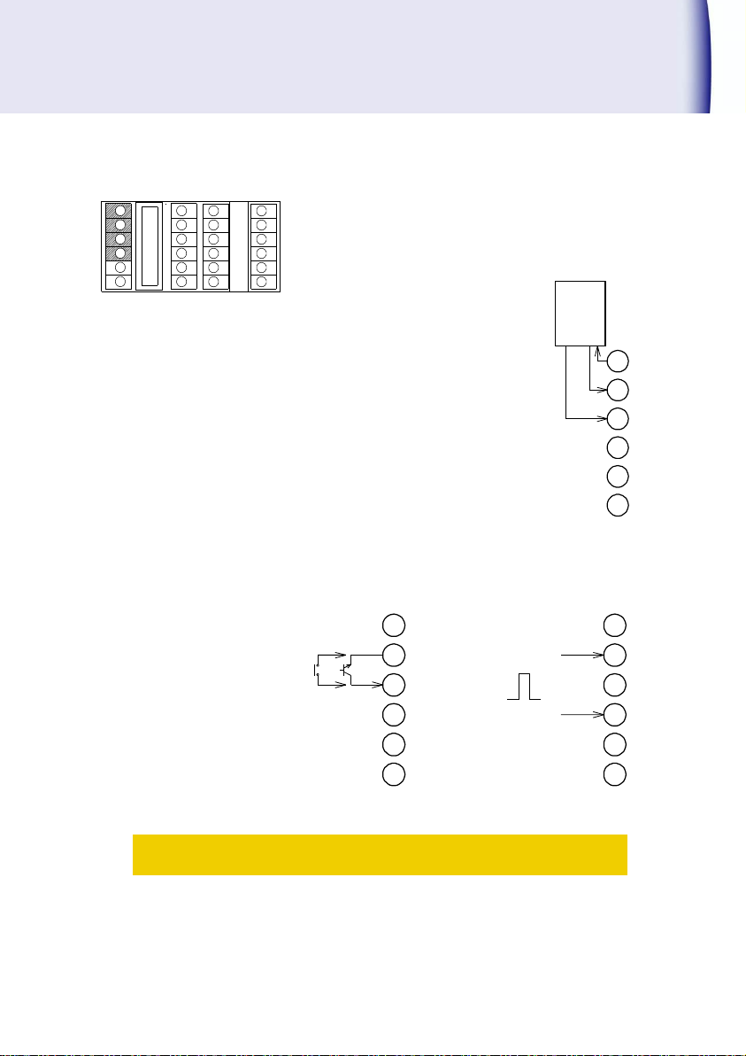
Power supply for the sensor is connected from terminal No.
A1-A3. If the power supply of sensor is applied from
external sources, the connection of terminal No. A1 will not
be required. When sensor power source is not used, A1 will
be vacant and do not used it for other purpose.
○+Sensor power supply
Connection example of(+V、0V)
○Connection example of measurement input
1
2
3
4
5
6
A B C D E
A1
A2
A3
A4
A5
A6
COM
SIG1
SIG2
SENSOR
NC
NC
Sen sor ou tput
(Open co llector )
+V0V
Power su pply
for sens or
A1
A2
A3
A4
A5
A6
COM
SIG1
SIG2
A1
A2
A3
A4
A5
A6
COM
SIG1
SIG2
0V
OUT
SENSOR SENSOR
NC
NC
NC
NC
4.0~30V
0~1.5V
No volt age contac t or
NPN open collector sensor sensor
Voltage pulse out put
Connection of input signal
471C 13
If sensor power supply terminal A1 is accidentally short-circuited with
COM terminal A2, it may cause malfunction of the product.
! Caution
Page 16
Installation(contd.)
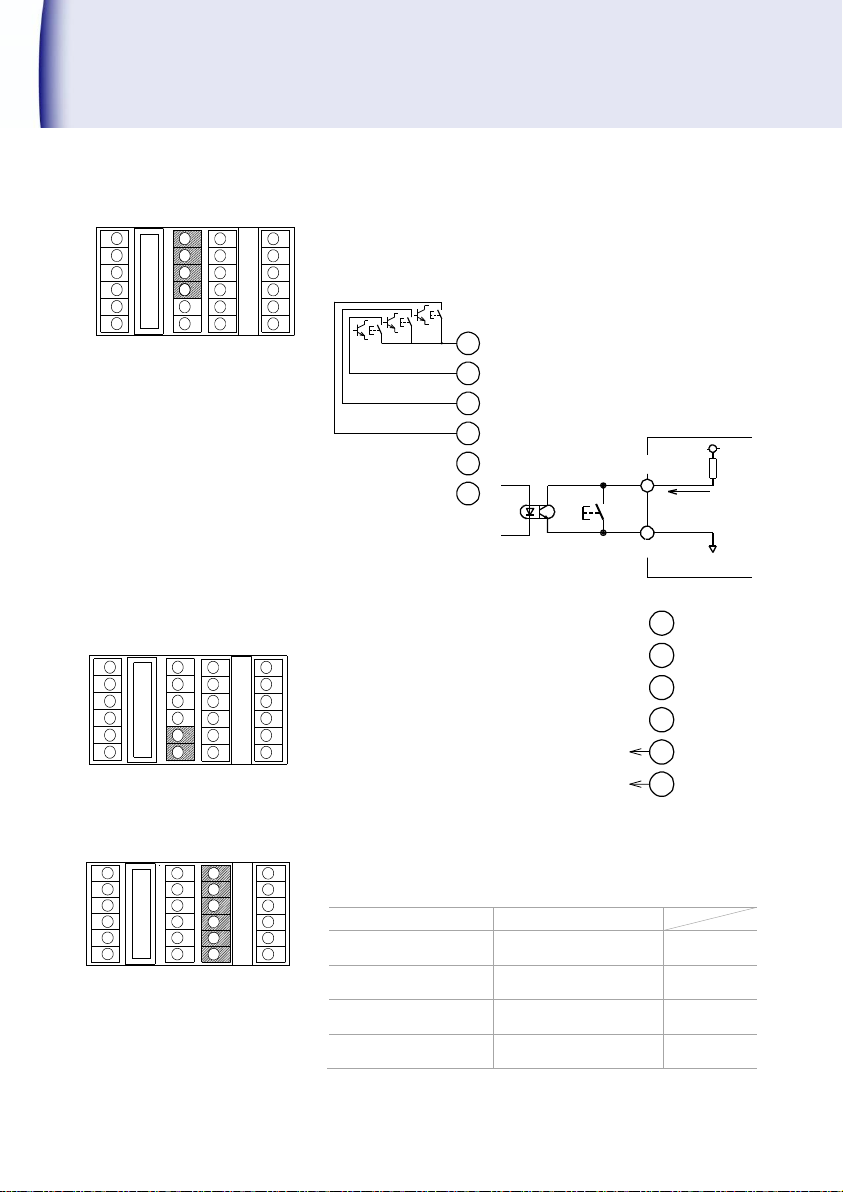
Input signals is set during the selection of memory of
comparative setting value. The configuration is as below.
Refer P.28 to confirm the Enable /Disable function of
comparative output.
The analog output can be obtained from
the Terminal No.C5-C6. Use analog
output within the specified range of
allowable load resistance.
(Refer Page 26『Model Configuration』)
Comparison output can be obtained in terminal No.
○D2 -○D1 、○D2 -○D3 、○D5 -○D4 and ○D5 -○D6 .
Equal NG
Equal GO
Displayed value≧
Higher (HH) set value
Displayed value>
Higher (HH) set value
HH:
○
D2
-○D1
Displayed value≧
High(H) set value
Displayed value>
High(H) set value
H:
○
D2
-○D3
Displayed value≦
Low(L) set value
Displayed value<
Low(L) set value
L:
○
D5
-○D4
Displayed value≦
Lower(LL) set value
Displayed value<
Lower(LL) set value
LL:
○
D5
-○D6
Contact capacity:AC/DC250V 200mA
1
2
3
4
5
6
A B C D E
1
2
3
4
5
6
A B C D E
1
2
3
4
5
6
A B C D E
C1
C4
C5
C6
C2
C3
M.COM
M.SEL1
M.SEL2
M.SEL4
+5V
Less than 10mA
Photocouplers
M.COM
M.SEL1/2/4
Switch
471C internal
C1
C2
C3
C4
C5
C6
A.OUT+
A.OUT-
Connection of selected memory for comparison
Connection of analog output
Connection of comparison outputs (HH,H,L,LL)
14 471C
Page 17
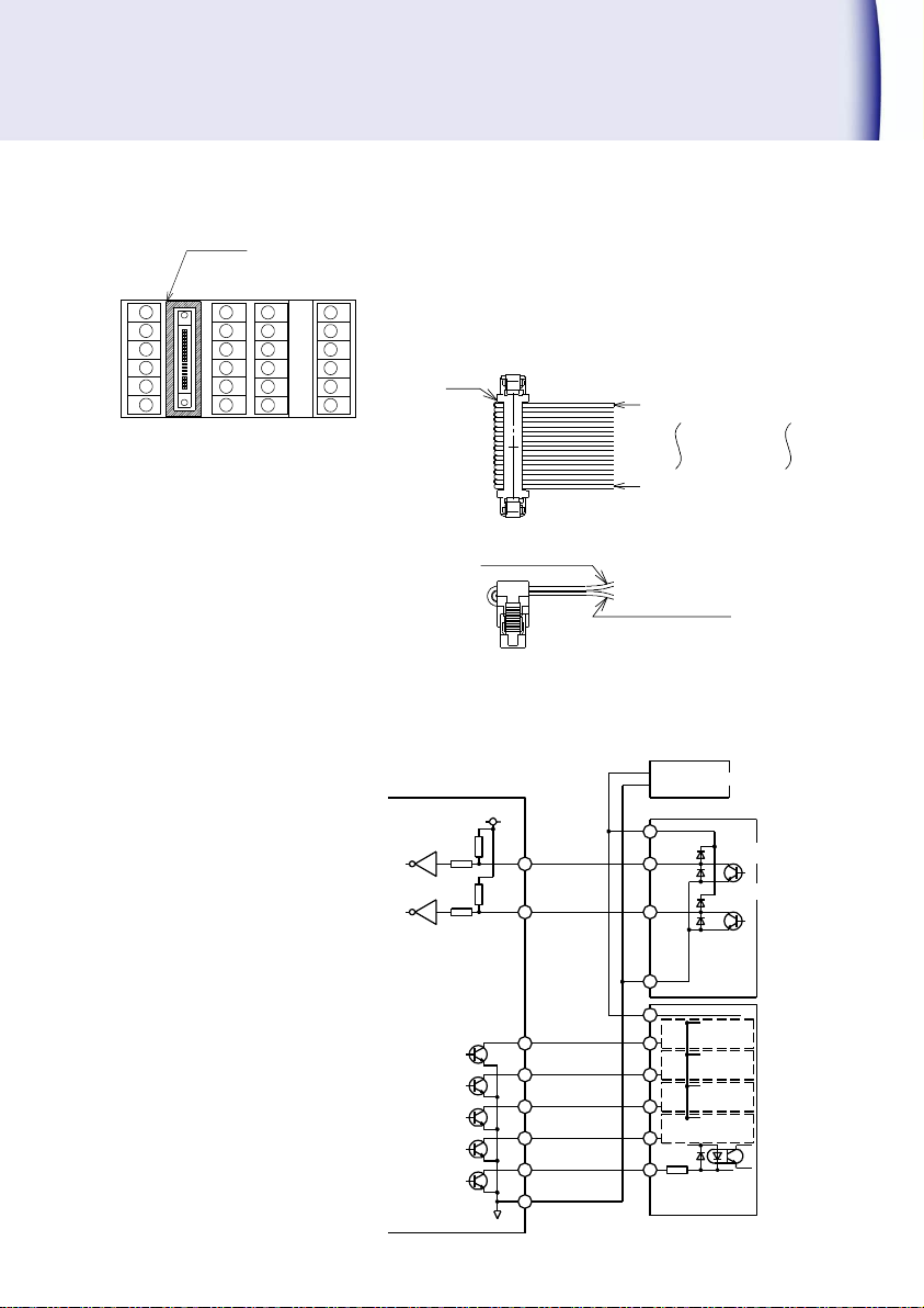
The configuration of 6 digits data output open collector
(NPN) is shown as the connector arrangement of BCD
output in page 11.
Control input pin 16 BCD_LATCH, 17 OUTPUT ENABLE are
shown in P.11 as the connector arrangement.
Accessory: Cable (5808-05) 2m
Connector (8822E-036-171-F, Kel Corp.)
Electrical schematic diagram
1
2
3
4
5
6
A B C D E
▲Mark
▲Mark
Lower cable No.19~36
Upper cable No.1~18
Upper cable
No.1(Brown)
Upper cable
No.18(Gray)
Lower cable
Lower cable
No.19(White)
No.36(Blue)
0V
24V
(0V)
OUT
OUT
0V
DC24V
DC24V
IN
IN
IN
IN
IN
16 BCD_LATCH
0
0
0
0
471C
15 OVER
1 1×10
2 2×10
4 8×10
3 4×10
18,35 ,36DAT A COM
ENABLE
17 OUTPUT
DC power supply
Transistor output unit
Controller side
Transistor output unit
Daringto n
Connection of BCD output
471C 15
Page 18
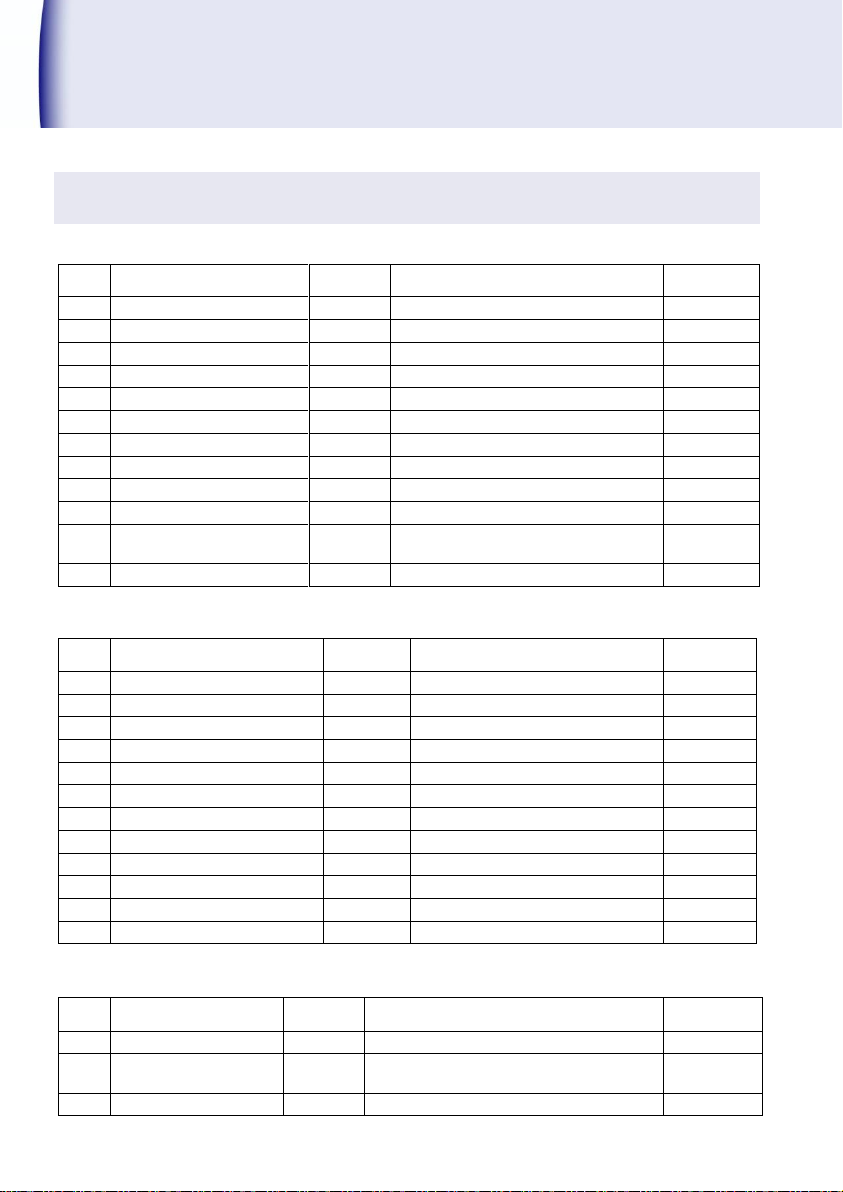
Usage of Function Code
Code
№
Function
Display1
Setting range
Default
Value
00
Key protect
KEY.
OFF, ON
OFF
01
Scale α
SCAL
000001E-9 to 999999E-0
000001E-0
02
Decimal point
DP
0/0.0/0.00/0.000/0.0000/0.00000
0
03
Input frequency filter
FLTR.
0.02kHz/10kHz/30kHz/100kHz
10kHz
04
Display cycle
RATE
00.1 to 19.9s
01.0
05
Number of moving average
M.AVE.
01 to 10
1
06
Min. revolution No.
MIN.R.
000000 to 999999
000000
07
Cut-off time
CUT
000.1 to 150.0
006.0
08
Predicted function
P.F.
OFF(Invalid)/ON(Valid)
OFF
09
Display of SV1, SV2
SUB.
OFF-OFF, PM-BM / OFF,HH,H,L,LL,PM-BM
*1)
PM-BM
10
Display switch-off function
TURN.
0(OFF)/1(All display)/2(SV1, SV2),
0 to 99 minutes
0.01
11
Display color
COLO.
R(Red), G(Green)
G(Green)
Code
№
Function
Display1
Setting range
Default
Value
40
Memory-enable
MEM.
OFF(Invalid)/ON(Valid)
OFF
41
HH compared value
AL.HH
000000 to 999999 *2)
999999
42
H compared value
AL. H
000000 to 999999 *2)
999999
43
L compared value
AL. L
000000 to 999999 *2)
000000
44
LL compared value
AL.LL
000000 to 999999 *2)
000000
45
Hysteresis
HYS.
01 to 99
01
50
Power-on delay
P.DLY
1 to 99 seconds
1
51
HH comparison function
FRM.HH
OFF/ON
ON
52
H comparison function
FRM. H
OFF/ON
ON
53
L comparison function
FRM. L
OFF/ON
ON
54
LL comparison function
FRM.LL
OFF/ON
ON
55
Comparison condition
EQUL
GO (Equal ‘GO’), NG (Equal ‘NG’)
GO
Code
№
Function
Display1
Setting range
Default
Value
70
BCD logic switching
B.PN
0: Negative, 1: Positive
0: Negative
76
Digit selection
D.SEL.
0 (Last 4digits), 1 (Middle 4 digits),
2 (First 4 digits)
0
79
Full-scale
A.FUL.
0 to 9999
9999
Function code list
●Display functions
*1)Display settings of HH,H,L,LL become enable, when comparison output function is on.
● Option comparison output function(HH,H,L,LL)
*2)The settings of MEM 1 to 8 become enable, when code No.40 ’Memory-enable’ function is on.
●Option BCD output, Analog output
16 471C
Page 19
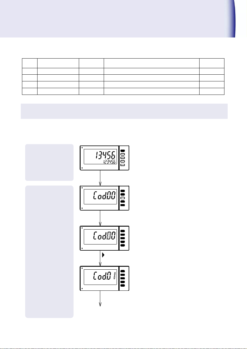
Measurement
Operation
Mode Setting
(Set Code No.)
Code
№
Function
Display1
Setting range
Default
Value
80
Baud rate
BAUD.
4800, 9600, 19200bps
9600bps
81
Parity
PARIT
non(None), odd(Odd no.), even(Even no.)
non
82
BCC switching
BCC
ON, OFF
OFF
83
Device number
RS.NO.
0 to 99
00
Identification of the key color during
set up is as follows.
Black key: Valid key
White key: Invalid key
[Common during the Setting mode
]
During setting mode, if the key is not
operated for about 5 minutes, the
operation returns into measurement
mode automatically. At this time, the
setting contents are not saved.
Again, if P・B key is pressed for more
than 1 second, the setting value
which may be under changing
process becomes invalid and returns
to measuring process.
MODE
▲
SET
SET
SET
MODE
Press 1 sec.
Confirm
Select the Code №
,▲
To function setting
●Option RS-232C, RS-485 output
Setting method of code No.
This is the basic input method of function code.
Following the setting of the Code No., perform the function setting on the following pages.
471C 17
Page 20
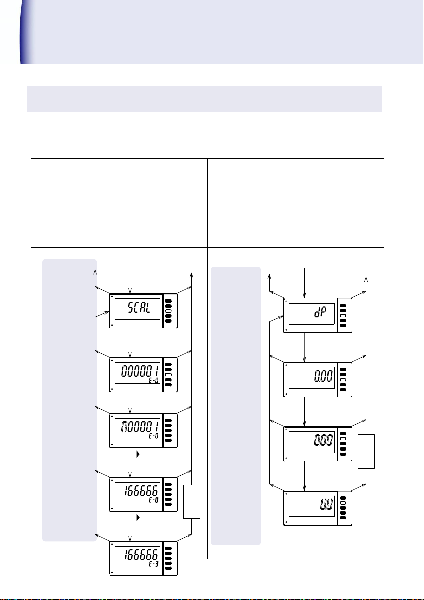
Usage of Function Code(contd.)
Mode
Setting
(Set number)
Mode
Setting
Code No.01『Scale α』
Code No.02『Decimal point』
Mantissa and exponent portion of scale α can
be set.
display=f×α
f:Input frequency, α: Scale value
Setting range:
000001×10-9 to 999999×10-0
The decimal point at an arbitrary position can
be lit up. The decimal point is not linked with
the setting of Scale α.
It's just a function to display the decimal point
of indication externally.
Setting range:
0/0.0/0.00/0.000/0.0000/0.00000
Ex.)Change from 000001E1-0 to 166666E-3.
Ex.)Change from 0.00 to 0.0.
▲
MODE
MODE
▲
MODE
MODE
MODE
SET
SET
SET
SET
▲
To code No. setting
To measurment
operation
1sec.
ENTER
Code №02
1sec.
ENTER
1sec.
ENTER
Displays of
current setting
(Save)
Memorize
exponent portion
Change the position of
1sec.
ENTER
▲
MODE
▲
MODE
ENTER
MODE
SET
SET
To code No. setting
Code №01
To measurment
operation
1sec.
ENTER
Displays of
current setting
1sec.
ENTER
MODE
MODE
MODE
SET
SET
SET
1sec.
(Save)
Memorize
,▲
Change
mantissa portion
Change
exponent portion
ENTER
1sec.
ENTER
1sec.
,▲
Function setting method
The following is an example of the input function setting. Refer this page when changing to the
setting other than factory setting value. Continue the following operation of the function setting
after completion of setting method of code No. mentioned in previous page (page 17).
18 471C
Page 21
Mode
Setting
(Item setting
Mode
Setting
(Set number)
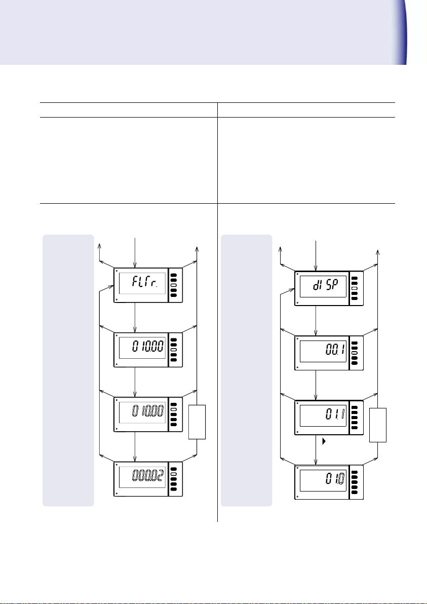
Code No.03『Input frequency filter』
Code No.04『Display cycle』
The High limit of Input frequency can be set.
Set the Input frequency filter bigger than the
max. frequency of Input signal.
Setting range: 100.00:0.0067Hz to 100kHz
030.00:0.0067Hz to 30kHz
010.00:0.0067Hz to 10kHz
000.02:0.0067Hz to 20 Hz
Averaged of new display cycle is shown.
Setting range:00.1s to 19.9s
Ex.)Change from 10kHz (010.00) to 20Hz
(000.02)
Ex.)Change from 00.1 to 01.0
▲
MODE
MODE
▲
MODE
MODE
MODE
SET
SET
SET
SET
Code №04
,▲
To code No. setting
To measurment
operation
1sec.
ENTER
Displays of
current setting
1sec.
ENTER
1sec.
ENTER
1sec.
ENTER
(Save)
Memorize
Change of setting
▲
MODE
MODE
▲
MODE
MODE
MODE
▲
SET
SET
SET
SET
Code №03
To code No. setting
To measurment
operation
1sec.
ENTER
1sec.
ENTER
1sec.
ENTER
1sec.
ENTER
(Save)
Memorize
Displays of
current setting
Change of setting
471C 19
Page 22
Usage of Function Code(contd.)
Mode
Setting
(Set number)
Mode
Setting
(Set number)
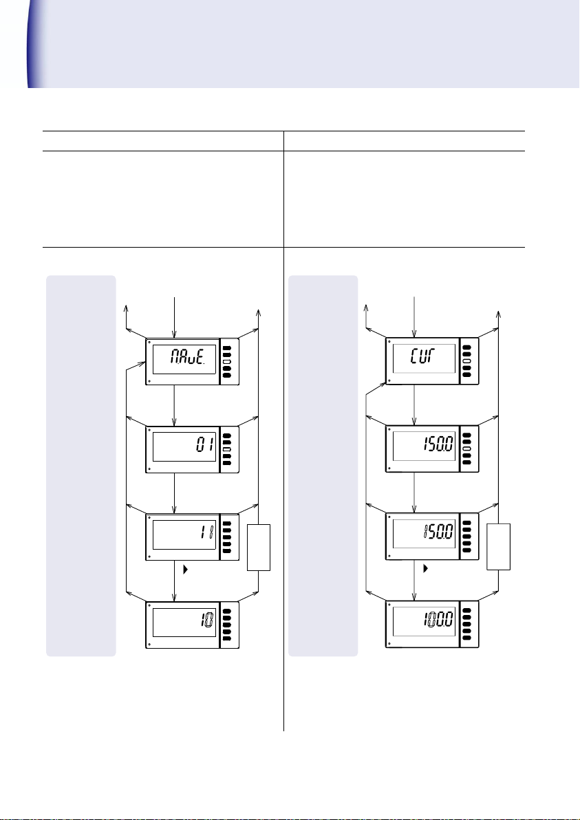
Code No.05『Number of moving average』
Code No.07『Cut-off time』
The measured value of display cycle calculated
by the moving average is displayed.
Setting range:01 to 10 times
‘0’ display is shown when no signal comes over
the Cut-off time regardless of display cycle.
Set time longer than min. frequency time of
input signal.
Setting range:000.1 to 150.0s.
Ex.)Change from 01 to 10.
Ex.)Change from 150.0 to 100.0.
MODE
MODE
MODE
▲▲
MODE
MODE
SET
SET
SET
Code №07
To code No. setting
To measurment
1sec.
ENTER
operation
Displays of
1sec.
ENTER
current setting
1sec.
ENTER
1sec.
ENTER
,▲
of setting
Change
(Save)
Memorize
▲
MODE
MODE
▲
MODE
MODE
MODE
SET
SET
SET
SET
Code №05
To code No. setting
To measurment
1sec.
ENTER
Displays of
current setting
1sec.
ENTER
1sec.
ENTER
1sec.
ENTER
,▲
(Save)
Memorize
operation
of setting
Change
20 471C
Page 23
Mode
Setting
(Item setting
Mode
Setting
(Item setting
)
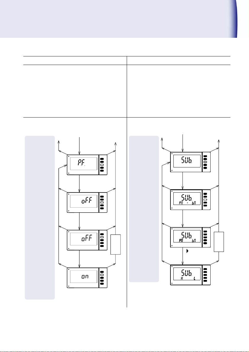
Code No.08『Predicted operation function』
Code No.09『SV1,SV2 display』
Display of linear calculation is predicted in
between after the stoppage of pulse input to
Cut-off time.
Setting range: ON(Valid)
OFF(Invalid)
The values of SV1 and SV2 can be set here.
1) Without Comparison output
Setting range :OFF(SV1, SV2 No Display)
PM BM(SV1:PM, SV2:BM)
2) With Comparison Output
Setting range:PM BM fixed(SV1:PM, SV2:BM)
OFF, HH, H, L, LL(SV1、SV2)
Ex.)Change from OFF to ON.
Ex.)Change 2)With Comparison output from
SV1:PM, SV2:BM to SV1:H, SV2:L.
Note:The display turs off, when the setting
values and HH, H, L, LL Comparison
function(Code No.51、52、53、54)are off.
▲
MODE
MODE
▲
MODE
MODE
MODE
▲
SET
SET
SET
SET
Code №08
To code No. setting
To measurment
1sec.
ENTER
operation
Displays of
1sec.
ENTER
current setting
1sec.
ENTER
1sec.
ENTER
of setting
Change
(Save)
Memorize
▲
MODE
MODE
▲
MODE
MODE
MODE
SET
SET
SET
SET
Code №9
To code No. setting
To measurment
1sec.
ENTER
operation
Displays of
1sec.
ENTER
current setting
1sec.
ENTER
1sec.
ENTER
,▲
of setting
Change
(Save)
Memorize
Function mentioned above are the main setting methods. The setting of the other operation
methods are also like the setting method of the Code No.01 to 09. The detail description of the
setting ranges are omitted here. Please perform the other setting when necessary referring the
Function Code List mentioned on Page 16.
471C 21
Page 24
Usable Operation
▲
SET
SET
SET
During measurment operation
(COMP)
Pless
3 sec.
1 sec.
ENTER
,▲
1 sec.
ENTER
1 sec.
ENTER
(Save)
Memorize
During setting,
to measuring operation.
if 'P.B' key is pressed for more than 1 sec,
new setting value becomes invalid and returns
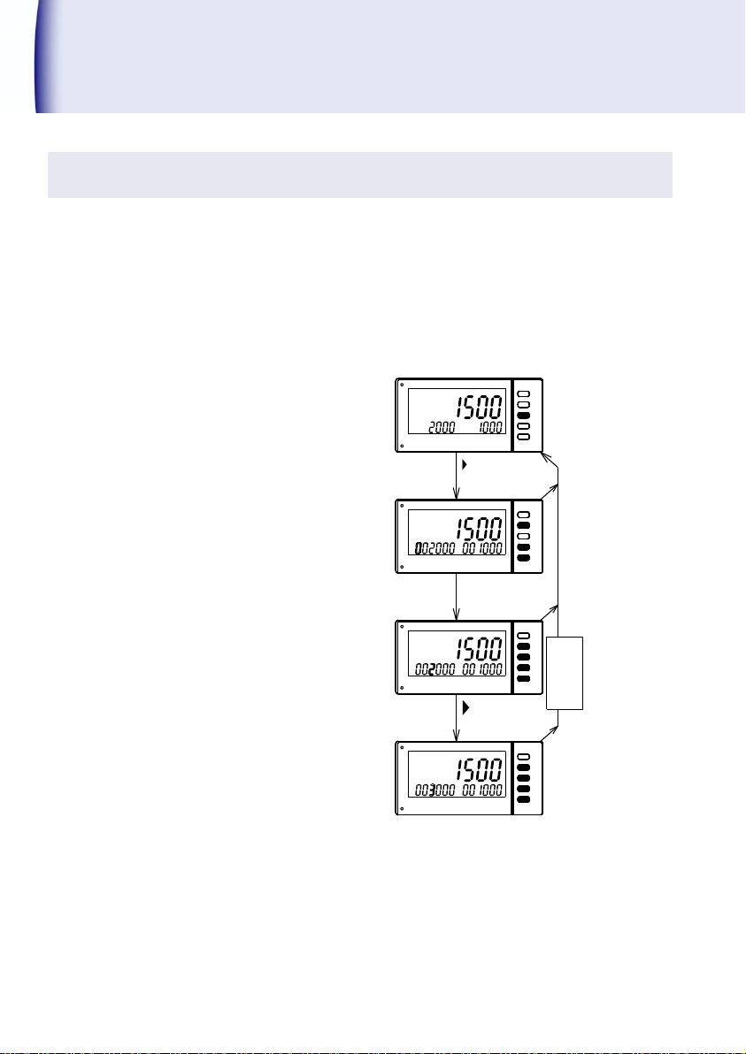
Changing comparison values of SV1 and SV2
When comparison values of SV1 and SV2 are displaying, the values of SV1 and SV2 can be
changed easily without using setting mode.
The Comparison values on SV1 and SV2 can be changed by pressing ▼(COMP) key for more
than 3 sec.
Ex.)Change from ‘SV1 002000、SV2 001000’ to ‘SV1 003000、SV2 001000’.
Note: This function cannot be used when Key-protection is valid.
22 471C
To use this function, cancel Key-protection.
Page 25
▲
SET
SET
SET
SET
SET
▲
,▲
1 sec.
ENTER
During measurment operation
▲
Pless
3 sec.
1 sec.
ENTER
1 sec.
ENTER
,▲
1 sec.
ENTER
1 sec.
ENTER
(Save)
Memorize
During setting,
to measuring operation.
if 'P.B' key is pressed for more than 1 sec,
If is pressed
after 10^0 (1 digit) digit,
decimal point can be set.
Set the decimal point
(Displayed point is set)
Set the value 15000
new setting value becomes invalid and returns
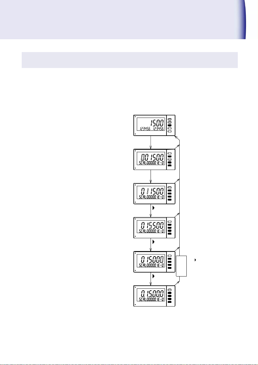
Teaching function
When the actual revolution number can be confirmed, the scaling calculation can be omitted.
The change of display values and error correction can be adjusted by using front panel keys
only.
Teaching function can not be used, when
revolution number is set beyond its range and
‘ERR2’ is displayed.
The calculated value of Scale α is rounded up
avoiding the decimal figure.
Setting value may not be displayed
depending on the setting of input and
Teaching function value.
When ▲Key is pressed for more than 3 sec.,
Teaching function can be activated.
Ex.) Change from the display of 1500 to
150.00
Note: This function can not be used, when
Key-protection is valid.
To use this function, cancel
Key-protection.
471C 23
Page 26
Usable Operation(contd.)
ENTER
SET
SET
SET
SET
▲
MODE
ENTER
MODE
During measurment operation
Mode setting
1 sec.
MODE
1 sec.
MODE
Display for 1 sec.
ENTER
Analog rated output
Analog rated output
Adjustment point
Adjustment point
0~ 5V
0~10V
1~ 5V
4~20mA
0~ 5V
0~10V
1~ 5V
4~20mA
10V
20mA
5V
5V
0V
0V
1V
4mA
▲
Memorize (Save)
Count down
▲ C ount up
Count down
▲ C ount up
Adjust output by multi-meter etc.
Adjust output by multi-meter etc.
Press
Press 2 sec.
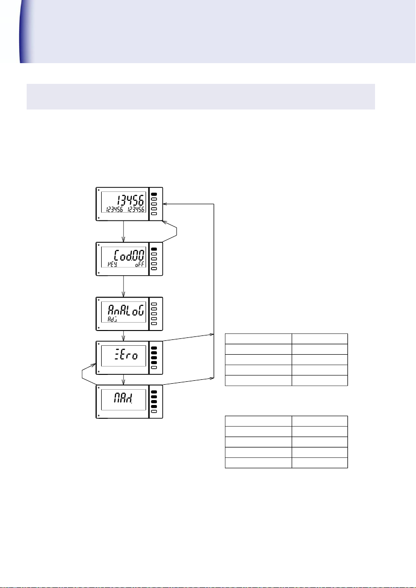
Adjustment of analog output (Option)
Fine Adjustment of Analog output (Option)can be done.
If MODE is pressed continuously during measurement, ‘ANALOG ADJ‘ is displayed and fine
adjustment can be done.
Note: This function can not be used, when Key-protection is valid.
24 471C
To use this function, cancel Key-protection.
Page 27
MODE
ENT ER
RESE T
MODE
ENT ER
RESE T
Power off
Power ON while pressing Enter
for more than 5 sec.
If Enter is released,
Restore to the factory.
setting returns to factory default value.
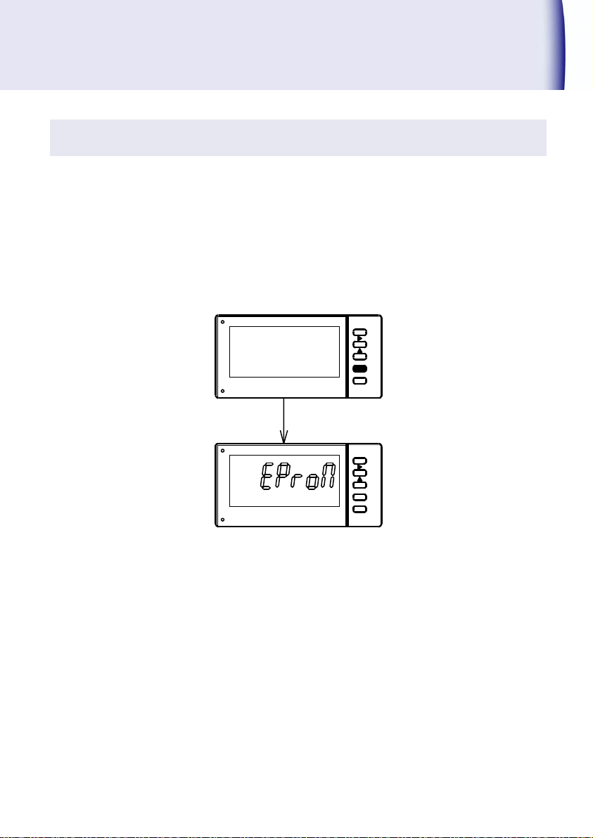
Restore to the factory setting
For the following case, restore to the factory setting first and then change to setting depending
on the specification and suitable requirement.
When display function or each output function of this model are required to change because
of the change of specification of sensor or measuring device.
When this model is used to instrumentation system having different specification.
※ By doing this, the setting range of Function code (Code No.01~83) and 『Adjustment of
Analog Output(Option)』 returns to the factory setting.
471C 25
Page 28
Specification
471C-
- - -
Power
supply
PhotoMOS
compare
output
Analog
output
Digital
output
Addition No.
Function
Symbol
Contents
①
Power supply
A
AC100 to 240V
9
DC24V
②
PhotoMOS
compare output
X
No output
2
4 photoMOS Relays (HH, H, L, LL)
③
Analog output
X
No output
Allowable load resistance
04
DC0~5V
More than 1kΩ
05
DC0~10V
More than 1kΩ
09
DC1~5V
More than 1kΩ
29
DC4 to 20mA
Less than 510Ω
④
Digital output
X
No output
DN
BCD output Open collector output(NPN)
E0
RS-232C
E1
RS-485
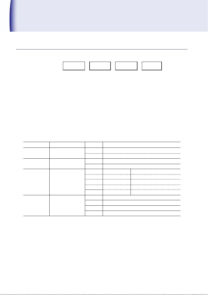
Model configuration
26 471C
Page 29
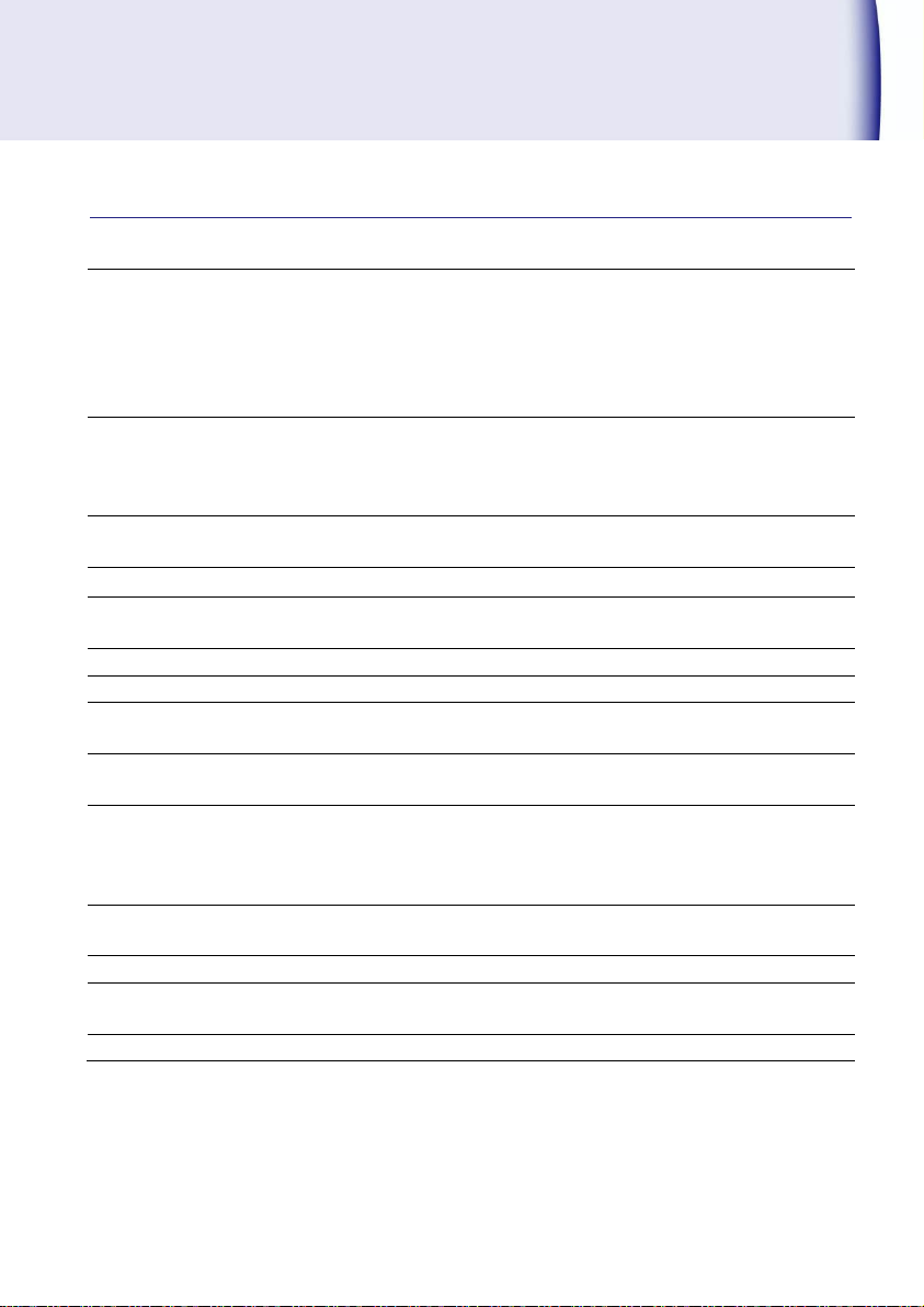
Measurement input
SIG1: No-voltage contact or NPN open collector
Open collector residual voltage less than 3V
Contact capacity DC12V 10mA
SIG2: Voltage pulse
Input resistance approx. 24kΩ
L=0 to 1.5V,H=4.0 to 30V
Display(LCD)
7segment display
Display1:Character height 15.2mm Red/Green
SV1,SV2: Character height 7.6mm White color
With zero suppress function
Display range
display1: 0 to 999999
SV1,SV2: 0 to 999999
Decimal point
101, 102, 103, 104, 105 Optional selection (External control not allowed)
Over display
display1OVER Light up during over(Red)
Exceeds 999999, OVER Light up ------displayed
Display cycle
Approx. 0.1 to 19.9s
Cut-off time
Approx. 0.1 to 150.0s
Min. Rotation
number
000000 to 999999
Moving average
Number
1 to 10 times
Input Frequency
0.0067Hz to 100kHz
0.0067Hz to 30kHz
0.0067Hz to 10kHz
0.0067Hz to 20 Hz
Display scale
display=f×α
f:Input frequency, α: Scale value 00001×10
-9
to 99999×10-0
Display accuracy
± (0.008% + 1digit) at 23℃ ± 5℃ 45 to 75%RH
Power supply line
mixed noise
1000V(AC power supply)
Sensor power supply
DC12V ± 10% 80mA
General specification
471C 27
Page 30
Mode
Setting
Mode
Setting
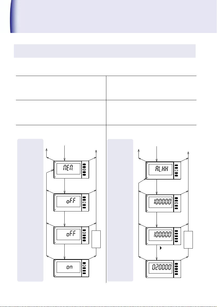
Code No.40『Memory enable』
Code No.41『HH compared value』
Code No.42『H compared value』
Code No.43『L compared value』
Code No.44『LL compared value』
This is the function where selected memory of
comparison can be set On or OFF.
Setting range: OFF(Invalid)
ON(Valid)
The compared value of HH, H, L, LL can be set.
【
When setting of ‘Memory Enable’(CodeNo.40)is OFF】
Setting range:0 to 999999
Ex.) Change from OFF to ON
Ex.) Change the compared value HH 100000 to
020000
▲
MODE
MODE
▲
MODE
MODE
MODE
▲
SET
SET
SET
SET
SET
Code №40
To code No. setting
To measurment
1sec.
ENTER
operation
Displays of
1sec.
ENTER
current setting
1sec.
ENTER
1sec.
ENTER
of setting
Change
Memorize
(Save)
MODE
MODE
MODE
▲▲
MODE
MODE
SET
SET
SET
SET
Code №41
To code No. setting
To measurment
1sec.
ENTER
operation
Displays of
1sec.
ENTER
current setting
1sec.
ENTER
1sec.
ENTER
,▲
of setting
Change
(Save)
Memorize
Option Output
PhotoMOS compare output
This is the setting change method of photoMOS compare output. Continue the following
operation after the steps (Setting method of Code No.) mentioned on page 17.
28 471C
Page 31
Mode
Setting
Item setting
+
Set numbers
Mode
Setting
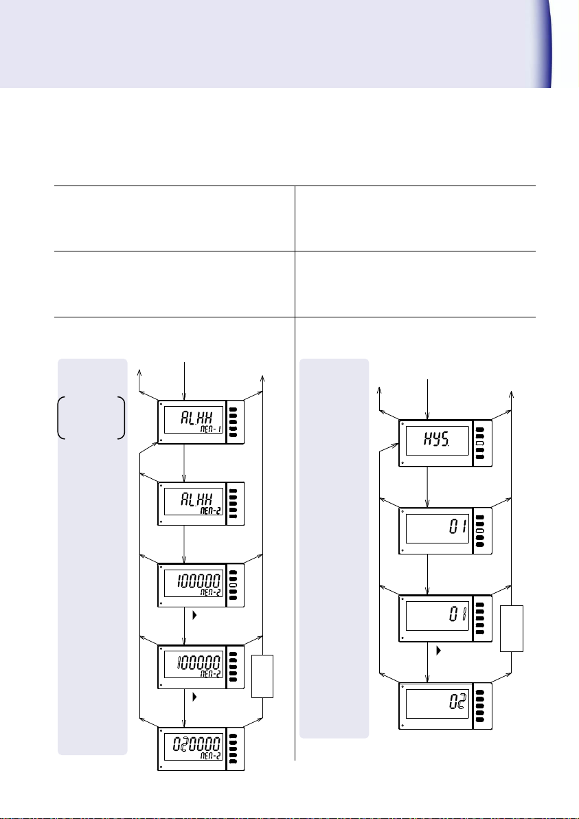
コードNo.45『Hysteresis』
The comparison value of HH, H, L, LL can be set.
【Setting of ‘Memory Enable’(
Code
No.40)is ON】
Setting range: Memory No.1 to 8
0 to 999999
The width of HH, H, L, LL comparison can be set.
Setting range:01 to 99
Ex.) Change comparison value HH Memory
No.2 from 100000 to 020000.
Ex.) Change Hysteresis from 01 to 02.
▲
MODE
MODE
▲
MODE
MODE
MODE
SET
SET
SET
SET
Code №45
To code No. setting
To measurment
1sec.
ENTER
operation
Displays of
1sec.
ENTER
current setting
1sec.
ENTER
1sec.
ENTER
,▲
of setting
Change
(Save)
Memorize
MODE
MODE
MODE
▲
MODE
MODE
SET
SET
MODE
SET
SET
SET
▲
To code No. setting
To measurment
1sec.
ENTER
operation
1sec.
ENTER
1sec.
ENTER
1sec.
ENTER
,▲
(Save)
Memorize
Code №41
Display of current
comparison values.
Change the
comparison values.
Chenge the mem ory No.
471C 29
Page 32
Mode
Setting
Mode
Setting
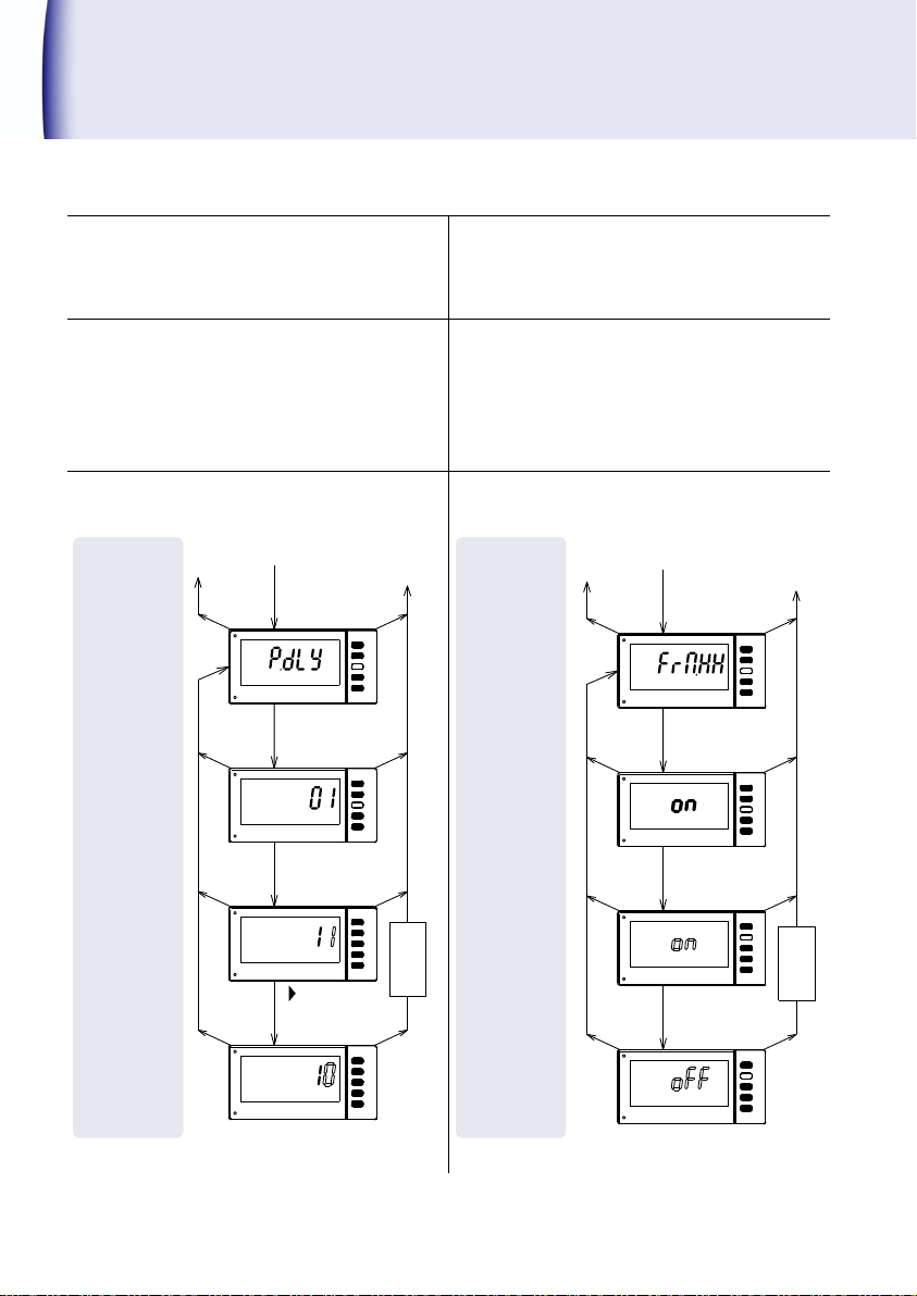
Code No.50『Power-on delay』
Code No.51『HH comparison function』
Code No.52『H comparison function』
Code No.53『L comparison function』
Code No.54『LL comparison function』
When power is supplied, set the time until
comparison output becomes ON.
Setting range:01 to 99s
The comparison function HH, H, L, LL can be
set.
Setting selection:
OFF(No Comparison function)
ON(With comparison function)
Ex.) Change from 01 to 10.
Ex.) Change comparison value HH from ON to
OFF.
▲
MODE
MODE
▲
MODE
MODE
MODE
SET
SET
SET
SET
Code №50
To code No. setting
To measurment
1sec.
ENTER
Displays of
1sec.
ENTER
current setting
1sec.
ENTER
1sec.
ENTER
,▲
of setting
Change
(Save)
Memorize
operation
▲
MODE
MODE
▲
MODE
MODE
MODE
▲
SET
SET
SET
SET
SET
Code №51
To code No. setting
To measurment
1sec.
ENTER
operation
Displays of
1sec.
ENTER
current setting
1sec.
ENTER
1sec.
ENTER
of setting
Change
(Save)
Memorize
Option Output(contd.)
30 471C
Page 33
Mode
Setting
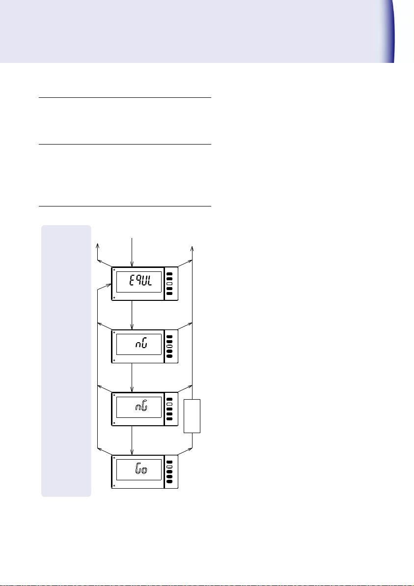
コードNo.55『Comparison condition』
Switching the comparison condition of HH, H,
L, LL to Equal NG or Equal GO can be done.
Setting selection:GO,NG
Ex.) Change from NG to GO.
▲
MODE
MODE
▲
MODE
MODE
MODE
▲
SET
SET
SET
SET
SET
Code №55
To code No. setting
To measurment
1sec.
ENTER
operation
Displays of
1sec.
ENTER
current setting
1sec.
ENTER
1sec.
ENTER
of setting
Change
(Save)
Memorize
471C 31
Page 34

Option Output(contd.)
Accuracy
±(0.5% of F.S.) at 23℃±5℃
Output cycle
Approx. 100ms
Response speed
Approx. (1/Input frequency) + 100ms+125ms
Condition Input frequency (0→less than 10Hz),
Input frequency filter (0.02kHz),
Display cycle(100ms),0→100% output
Approx. 100ms + 225ms
Condition Input frequency (0 → more than 10Hz),
Input frequency filter (0.02kHz),
Display cycle (100ms),0→100% output
Select the digit of output data
Selection of Display1 and setting mode can be selected
either one type of first 4 digits or middle 4 digits or last 4
digits from 6 digit display .
Output Scaling
Full scale setting range 0000 to 9999
Analog output
Refer page 9 for "Wiring method" of this manual for the connector arrangement. Also refer page
26 for “Model configuration” of the rated output and external resistance load.
The measurement input and the analog output are insulated.
32 471C
Page 35
Mode
Setting
Mode
Setting
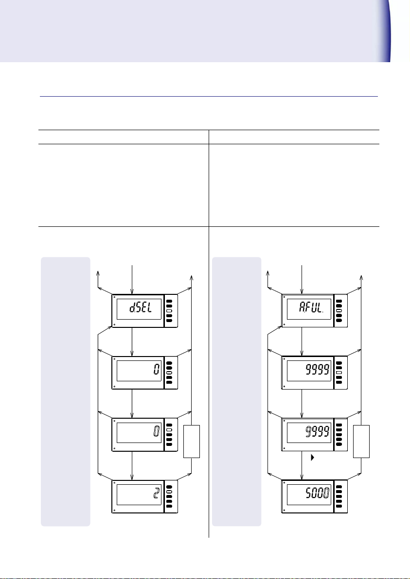
Code No.76『Selection of digit』
Code No.79『Full scale of analog output』
Out of 6 digits, analog output can be obtained
by 4 digits conversion. That 4 digits can be
selected from the last 4 digits, middle 4 digits
or the first digits.
Setting selection: 0(last 4 digits),
1(middle 4 digits),
2(first 4digits)
The display equivalent to the max. value can
be specified.
Setting range:0000 to 9999
Ex.) Change from 0(last 4 digits) to 2(first 4
digits).
Ex.) Change of analog display setting from full scale
9999 to 5000.
MODE
MODE
MODE
▲
SET
SET
SET
SET
▲
MODE
MODE
Code №79
,▲
To code No. setting
To measurment
1sec.
ENTER
operation
Displays of
1sec.
ENTER
current setting
1sec.
ENTER
1sec.
ENTER
of setting
Change
(Save)
Memorize
MODE
MODE
MODE
▲
SET
SET
SET
SET
▲
MODE
MODE
▲
To code No. setting
To measurment
1sec.
ENTER
operation
Displays of
1sec.
ENTER
current setting
1sec.
ENTER
1sec.
ENTER
of setting
Change
(Save)
Memorize
Code №76
Function setting
This is the setting change method of analog output. Continue the following operation after the
steps (Setting method of Code No.) mentioned on page 17.
471C 33
Page 36

Option Output(contd.)
Open collector
Sink type、Contact capacity DC30V10mA
Data BCD6digits
display1output ON(Negative logic), OFF(Positive logic)
Over(OVER)
Exceeds 999999, output ON(Negative Logic), OFF(Positive Logic)
Decimal point(DP1 to 4)
Output in correspond to the display of decimal point
ON(Negative logic), OFF(Positive logic)
Polarity (POL)
+ OFF(Negative logic), ON(Positive logic)
Logic switching
Logical setting of Data, Over, Decimal point and Polarity can be set
to switch.
Synchronization signal
(SYNC)
Pulse output become ON approx. for 10ms
Read the data at good SYNC rising time.
BCD output cycle
Approx. 100ms
Input current
Less than 1mA, OFF(H Level)=3.5 to 5V, ON (L Level)=0 to 1.5V
BCD_Latch
(BCD_LATCH)
When BCD_Latch pin is short circuited with DATA COM or set to L level,
only BCD is retained. Display is done continuously.
Data enable
(OUTPUT ENABLE)
When data enable pin is released (OFF), output data (OVER
INCLUDED) is obtained.
When data enable pin is shorted with DATA COM pin or set to L level,
data (OVER INCLUDED) becomes OFF state, SYNC output is prohibited,
and the connect to the system data bus becomes easy. (Display is not
retained).
BCD output (Digital output)
Refer page 9 for "Wiring method" of this manual for the connector arrangement.
The measurement input and the BCD output are insulated.
Output
Control input
Accessory:BCD Cable 2m(Model 5808-05)
34 471C
Page 37
Mode
Setting
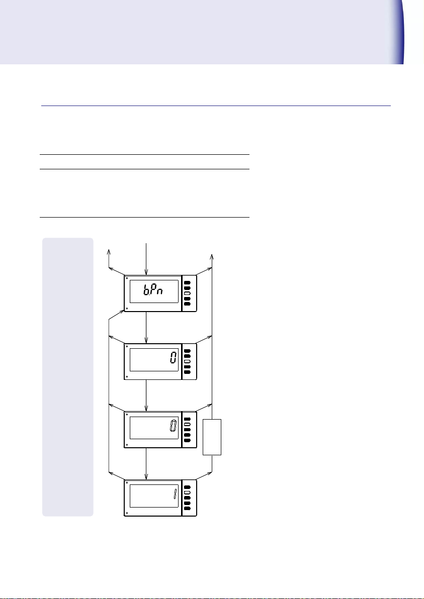
Code No.70『BCD output logic switching』
Logic setting of BCD data, over, decimal point and
polarity can be set to switch.
Setting selection: 0 (Negative logic), 1(Positive logic)
Ex.) Change from 0(Negative logic) to 1(Positive logic).
MODE
MODE
MODE
▲
SET
SET
SET
▲
MODE
MODE
▲
SET
Code №70
To code No. setting
To measurment
1sec.
ENTER
operation
Displays of
1sec.
ENTER
current setting
1sec.
ENTER
1sec.
ENTER
of setting
Change
(Save)
Memorize
Function setting
This is the setting change method of BCD output logic switching. Continue the following
operation after the steps (Setting method of Code No.) mentioned on page 17.
471C 35
Page 38

Memo:
36 471C
Page 39

471C 37
Page 40

Tsuruga Electric Corporation
Osaka Headquarters
1-3-23, Minamisumiyoshi, Sumiyoshi-ku, Osaka, Japan, 558-0041
TEL 81-6 -6692-6700, FAX 81-6 -6609- 8115
E-mail: ft[email protected]
Yokohama office
1-29-15, Shinyokohama, Kohoku-ku, Yokohama, Kanagawa, Japan, 222-0033
Tokyo Office
5-25-16, Higashigotanda, Shinagawa-ku, Tokyo, Japan, 141-0022
Nagoya Office
Sun Park Higashi Betsuin Bld. 2F
5-19, Oicho, Naka-ku, Nagoya, Aichi, Japan, 460-0015
Osaka Plant
1-3-23, Minami Sumiyoshi, Sumiyoshi-ku, Osaka, Japan, 558-0041
Shiga Plant
122, Kawasaki-Cho, Nagahama, Shiga, Japan, 526-0846
www.tsuruga.co.jp
I-02394
Page 41
RS-232C
Output
RS-485
Tachometer
471C
Quick Manual
Page 42

内容
Contents
About this booklet ······································ 1
Model name for communication output
Connector arrangement and connection method
RS-232C ············································································· 2
RS-485 ··············································································· 2
············· 1
·················· 2
Function code ············································· 3
Communication command (RS-232C, RS-485 common)
Instructions about the comment ············································ 4
Command/Response ··························································· 5
Command list ······································································ 8
··········· 4
Page 43
! Warning
This is the warning to avoid danger. Severe injure or fatal accident may
occur to the user in case the product is mishandled.
! Caution
This is the caution to avoid danger. Minor injury to the user or physical
obstacle may occur in case the product is mishandled.
Addition No.
Output specification
E0
RS-232C output
E1
RS-485 output
Transmission method
Asynchronous half duplex method
Transmission speed
4800,9600、19200bps
Data length
8bit
Parity
None, even number, odd number
Stop bit
1bit
Data
Conform to JIS 8 unit code
X Parameters
None
About this booklet
Thank you for purchasing Tsuruga product. This is the quick optional manual for RS-232C,
RS-485 output. Refer the quick manual of the main body for cautions beside the usage the
RS-232C, RS-485 output, installation, operation etc.
Before use of the product, read this quick manual carefully and thoroughly, and keep it available
for routine reference.
The following symbol marks are used in this quick manual for the safety use of the product.
Model name for communication output
471C-□-□-□-□
① ② ③ ④
④ Digital output
Common specification
The measurement input and the communication I / O are insulated.
1
Page 44
471C
DTE side (computer side)
Terminal
No.
Signal
name
Pin No.
Signal
name
D Sub 25 Pin
D Sub 9 Pin
B1
SD
3
2
6
8
4
5
20
7
1
2
3
6
1
7
8
4
5
RD
SD
DR
CD
RS
CS
ER
SG
FG
B2
RS
B3
RD
B4
CS
B5
SG
B6
NC
Shielded wire
Terminal
No.
Signal
name
Description
B1
+
"+" Indicates non-inverted output
B2
-
"-" indicates inverted output
B3
NC
B4
Term
When the terminals are short-circuited,
a terminating resistor of 200 Ω is connected
in parallel to the line.
B5
Term
B6
NC
SD
RS
RD
CS
SG
471C
RD
SD
DR
CD
RS
CS
ER
SG
2
3
6
1
7
8
4
5
-
D Sub 9P
Shield
Signal Signal Pin No.
Hood
Fixed screw: #4-40 inch short scr ew
B1
B2
B3
B4
B5
B6
Terminal
LIG HT-GREEN ,BLA CK
WIRE COLOR
ORA NGE,BLAC K
YEL LOW,BLAC K
-
ORANGE,R ED
YELLOW,R ED
FG
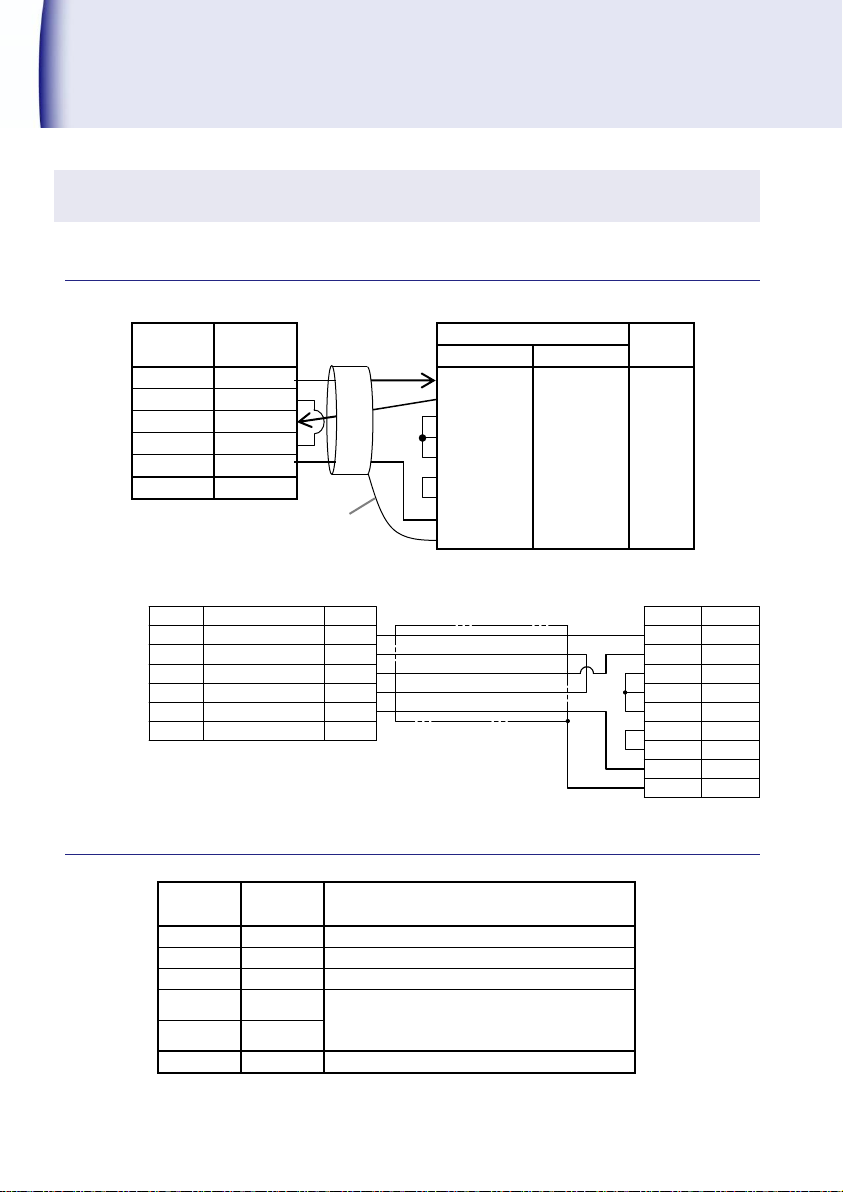
Connector arrangement and connection method
RS-232C
Optional:RS-232C cable 2 m(Model 5858-10)
RS-485
2
Page 45
Baud rate
(Code No.80):
Baud rate can be selected.
Setting Range 4800, 9600, 19200bps
Parity
(Code No.81):
Parity can be selected.
Setting Range non(None), odd(Odd no.), even(Even no.)
BCC switching
(Code No.82):
Selection with or without BCC can be done.
The results obtained by calculating the exclusive OR from immediately after
STX value to EXT (EXT included), are added after the ETX.
Setting Range ON, OFF
Device number
(Code No.83):
Device number can be selected.
Setting Range 0 to 99
- - +
-
+ - + G +
Recommended converter Equipment:
SI-30, Manufactured by LINEEYE CO. Ltd.,
RS-232C
(USB)
Converter
Shield wire
Terminator for
short-circuit
Host computer
№1
№2
№3
Connection
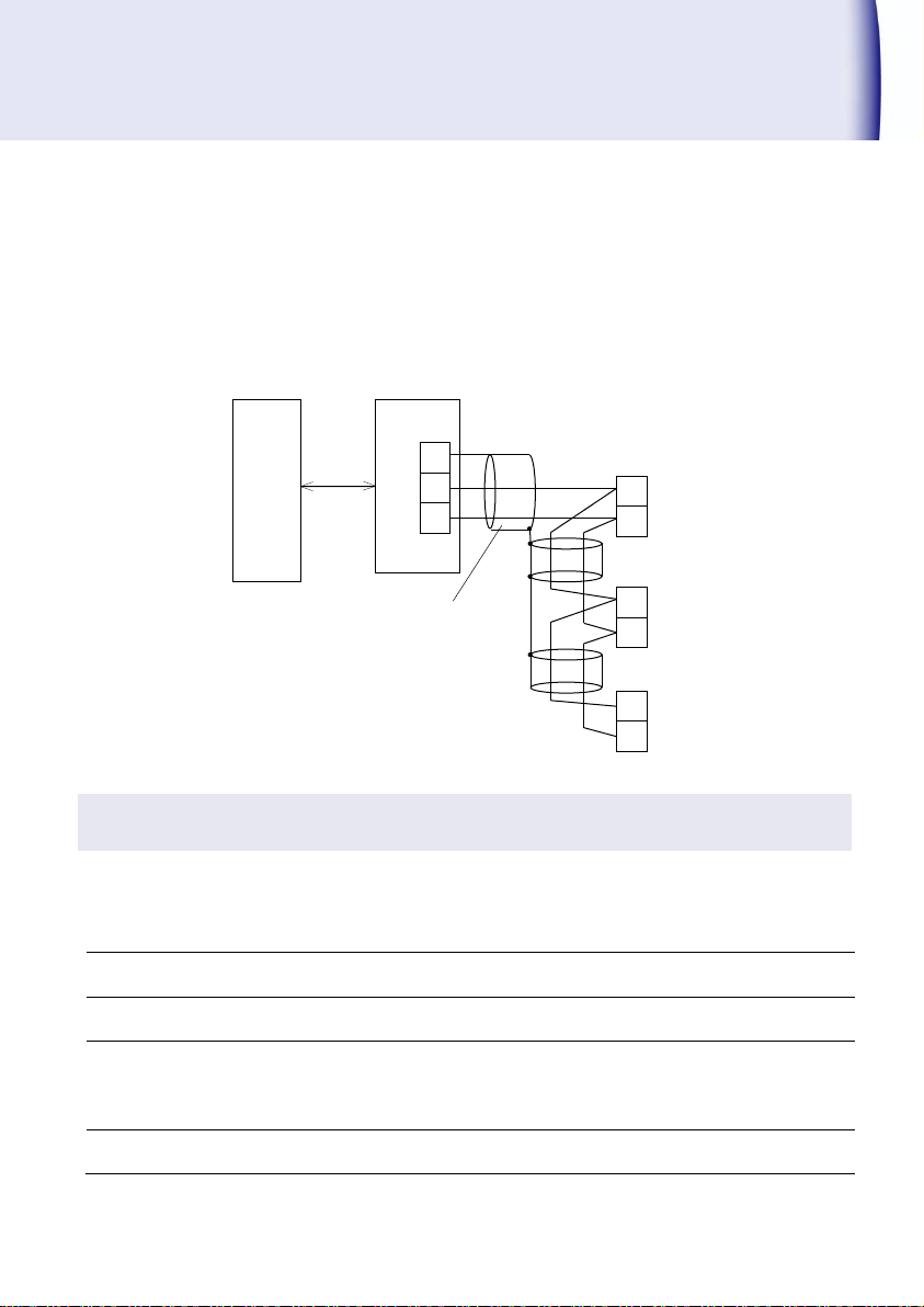
RS-485 can be linked up to 32 computers including the host computer. It is necessary to specify
the end station for the both end of the equipment in the transmission line. Make short circuit the
terminator for specific end station. Lead wire for short-circuit is not included. Besides that,
conduct the setting of the terminator by RS-232C/RS-485 converter.
Function code
Communication setting is done by front key operation. When changing to a setting other than
the factory set value, please refer " Setting method of code No." of the Quick Manual of model
471C on page 17.
3
Page 46

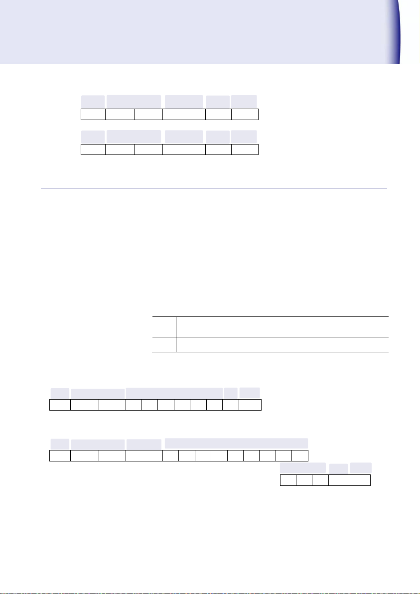
Command frame:
+ + + +
Response frame:
+ + + + +
Exit code
Contents
A(41H)
Normal end
B(42H)
Under setting (In case of communication during setting)
C(43H)
Setting error (Out of setting range or error)
D(44H)
BCC error (If BCC function is available)
P(50H)
Command error(When the received command becomes unable to analyze)
Command
Device No.
STX
ETX
(BCC)
Exit code
Device No.
STX
ETX
(BCC)
Response
Communication command (RS-232C, RS-485 common)
! Caution
About the command when power in turned ON,
When the power is turned ON, supply power should rise up to the rated
voltage within 1 second.
There have been some cases of not being able to response the command
even 3 seconds after the power supply reached the rated voltage
because of initialization of 471C. As there may be cases of responding
undefined data too, it is highly advised to communicate only after it has
reached to rated voltage more than 3 seconds.
Instructions about the comment
If there is BCC function, BCC is added after the ETX
The results obtained by calculating the exclusive OR from immediately after STX value to
EXT (EXT included), are added after the ETX.
Configuration of frame
Only first 4 characters of the command letters will be valid.
Example) “RMREAD” → “RMRE”
Setting items represented either by numbers or characters will be valid.
Example) “WC52 0” or “WC52 OFF”
Number setting
Set a value that does not include the decimal point of the display. (display cycle , cut-off
time , comparison value, analog output full scale)
Exit code:Returns to reception status of the command frame
4
Page 47
Response during the command error
(02H)
(30H)
(30H)
(50H)
(03H)
Response during the setting time.
(02H)
(30H)
(30H)
(42H)
(03H)
Response:
STX
Device No.:00
Exit code
_
+ 1 . 0 0 0 0
0
02H
30H
30H
41H
20H
2BH
31H
2EH
30H
30H
30H
30H
30H
E
+ 3 ETX
(BCC)
45H
2BH
33H
03H
○
a
_(20H space): Within measurement range
*(2AH): 6 digits over
○
b
Measurement value
Command frame:
STX
Device No.:00
R M R E A D ETX
(BCC)
02H
30H
30H
52H
4DH
52H
45H
41H
44H
03H
Exit code
Device No.:00
STX
ETX
(BCC)
Exit code
Device No.:00
STX
ETX
(BCC)
Command/Response
◆
Measurement command
Command :RMREaD Current value of requested data
Response :Response to RMREAD
◆
Current value of requested data
Command :RMREaD Read out current value data
Response :Response to RMREAD
Data format
_+1.99999E+3
a ○b
○
+1000.00
5
Page 48
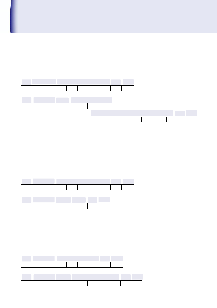
Command frame:
STX
Device No.:00
I
D N T
?
ETX
(BCC)
02H
30H
30H
49H
44H
4EH
54H
3FH
03H
Response:
STX
Device No.:00
Exit code
4
7 1 C
,
02H
30H
30H
41H
34H
37H
31H
43H
2CH
N o . 9 4 9 - 1 0
0
ETX
(BCC)
4EH
6FH
2EH
39H
34H
39H
2DH
31H
30H
30H
03H
Command frame:
STX
Device No.:00
A
L A R
M
ETX
(BCC)
02H
30H
30H
41H
4CH
41H
52H
4DH
03H
Response:
STX
Device No.:00
Exit code
0 1 ETX
(BCC)
02H
30H
30H
41H
30H
31H
03H
Response:
STX
Device No.:00
Exit code
0
0 2 0 0 0
ETX
(BCC)
02H
30H
30H
41H
30H
30H
32H
30H
30H
30H
03H
Command frame:
STX
Device No.:00
R
C 4 1
ETX
(BCC)
02H
30H
30H
52H
43H
34H
31H
03H
Reading of the device information
Command :IDNT? Reading of the device information
Response :Response to IDNT
471C, No. 949-100 [Model No., Software registration No. (Tsuruga)]
Reading of judgment
Command :ALARM Reading of Judgment
Response :Response to ALARM
※It provides the status of comparison output. In the example, it is the sum of
the weights of HH and H(01+02=03). Please, refer the Judgment Command
on page 9 for the detail reference.
01(HH output)
Reading of setting data
Command :RC41 HH comparison value setting reading
Response :Response to RC41
002000
6
(HH comparison value 002000 read)
Page 49
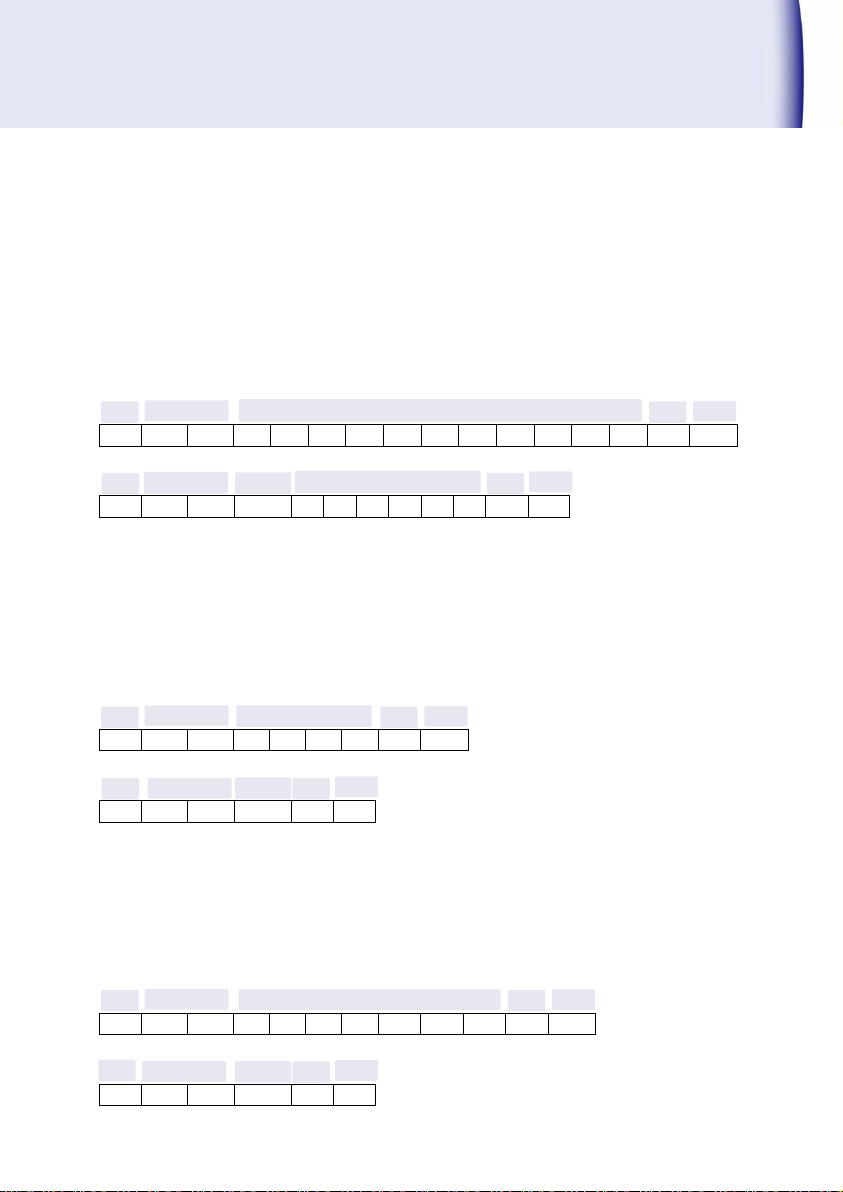
Command frame:
STX
Device No.:00
W
C 4 1 _ 0 0 2 0 0
0
ETX
(BCC)
02H
30H
30H
57H
43H
34H
31H
20H
30H
30H
32H
30H
30H
30H
03H
Response:
STX
Device No.:00
Exit code
0
0 2 0 0 0
ETX
(BCC)
02H
30H
30H
41H
30H
30H
32H
30H
30H
30H
03H
Command frame:
STX
Device No.:00
S
T O R
ETX
(BCC)
02H
30H
30H
53H
54H
4FH
52H
03H
レスポンス:
STX
Device No.:00
Exit code
ETX
(BCC)
02H
30H
30H
41H
03H
Normal exit
Command frame:
STX
Device No.:00
D
E F A
U L T
ETX
(BCC)
02H
30H
30H
44H
45H
46H
41H
55H
4CH
54H
03H
Response:
STX
Device No.:00
Exit code
ETX
(BCC)
02H
30H
30H
41H
03H
Normal exit
Setting of data setting
NOTE)When setting value of input frequency filter is changed during the measurement
process, measurement is stopped. The measurement can be started again after
completion required setting parameter.
Command :WC41_002000 HH comparison value setting
(HH comparison value set to 002000)
Response :Response to WC41_002000
002000
Memory control command
Write commend
Write the setting data into the EEPROM
Command :STOR
Response :Exit code
Memory Initialization
Command :DEFAULT
Response :Exit code
7
Setting data resets to the value during the factory shipment time. But, the transmission
speed, parity, BCC switch and device number cannot brought bring to default value.
Page 50
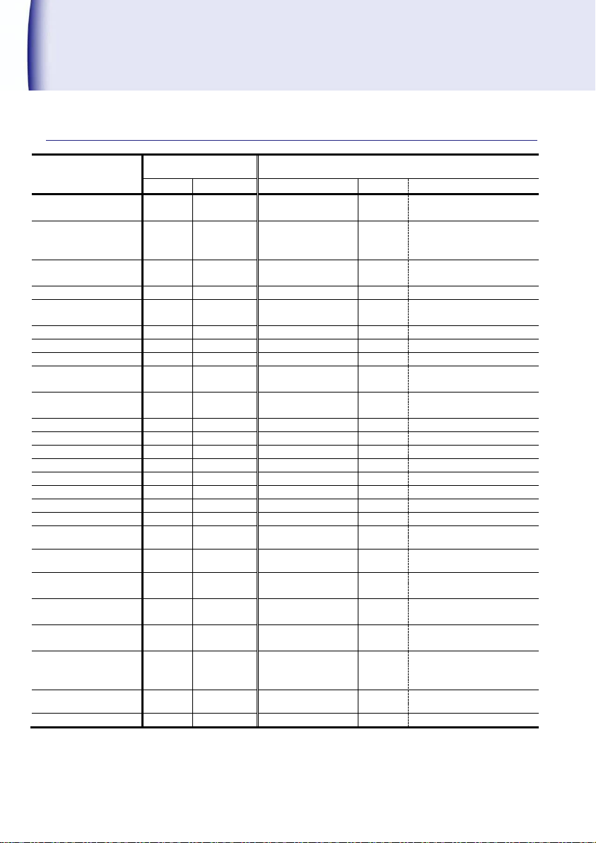
Setting command
Required setting
command
Specified setting command
Command
Response
Command frame
Response
Setting item, Range
Scale α
RC01
999999E-0
WC01 999999E-1
999999
E-1
000001~999999
Decimal point
RC02
0
WC02 1
1
0(0), 1(0.0), 2(0.00),
3(0.000),4(0.0000),
5(0.00000)
Input frequency filter
RC03
0
WC03 1
1
0(0.02kHz), 1(10kHz),
2(30kHz),3(100kHz)
Display cycle
RC04
001
WC04 199
199
001~199(0.1~19.9)
Number of moving
average
RC05
01
WC05 10
10
01~10
Min. revolution No.
RC06
000000
WC06 999999
999999
000000~999999
Cut-off time
RC07
0000
WC07 1500
1500
0000~1500(0.0~150.0)
Predicted function
RC08
0
WC08 1
1
0 (Invalid), 1(Valid)
Display of SV1, SV2
RC09
1,1
WC09 3,4
3,4
SV1,SV2:0(OFF),1(PM),
2(HH),3(H),4(L),5(LL)
Display switch-off
function
RC10
1,99
WC10 1,99
1,99
0 (Invalid), 1(All display)
2(SV1,SV2),0~99
Display color
RC11
0
WC11 1
1
0(RED),1(GREEN)
Memory-enable
RC40
0
WC40 1
1
1(ON)/ 0(OFF)
HH compared value
RC41
999999
WC41 999999
999999
000000~999999
H compared value
RC42
999999
WC42 999999
999999
000000~999999
L compared value
RC43
999999
WC43 999999
999999
000000~999999
LL compared value
RC44
999999
WC44 999999
999999
000000~999999
Hysteresis
RC45
0
WC45 01
01
01~99
Power-on delay
RC50
1
WC50 01
01
01~99
HH comparison
function
RC51
0
WC51 1
1
1(ON)/ 0(OFF)
H comparison
function
RC52
0
WC52 1
1
1(ON)/ 0(OFF)
L comparison
function
RC53
0
WC53 1
1
1(ON)/ 0(OFF)
LL comparison
function
RC54
1
WC54 0
0
1(ON)/ 0(OFF)
Comparison
condition
RC55
0
WC55 0
0
0(GO)/ 1(NG)
Digit selection of
analog output
RC76
0
WC76 0
0
0 (Last 4digits),
1 (Middle 4 digits),
2 (First 4 digits)
Full scale of analog
output
RC79
9999
WC79 9999
9999
0000~9999
Key protection
RC00
1
WC00 0
0
1(ON), 0(OFF)
Command list
8
Page 51
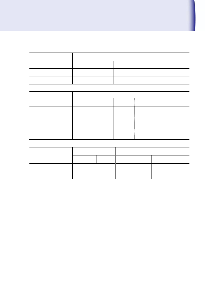
Command of
measurement data
Required measurement data command
Command
Response
Measurement data
RMREaD
_+1.00000E+3
Judgment command
(Result output of
currently judgment)
Judgment request command
Command
Response
Item
HH, H, L, LL
ALARM
00
Output status Weight of data
HH 01
H 02
L 04
LL 08
Memory control
command
Required control command
Specified control command
Command
Response
Command frame
Response
Write
STOR
Exit code
Initialization
DEFAULT
Exit code
9
Page 52

Tsuruga Electric Corporation
Osaka Headquarters
1-3-23, Minamisumiyoshi, Sumiyoshi-ku, Osaka, Japan, 558-0041
TEL 81-6 -6692-6700, FAX 81-6 -6609- 8115
E-mail: [email protected]
Yokohama office
1-29-15, Shinyokohama, Kohoku-ku, Yokohama, Kanagawa, Japan, 222-0033
Tokyo Office
5-25-16, Higashigotanda, Shinagawa-ku, Tokyo, Japan, 141-0022
Nagoya Office
Sun Park Higashi Betsuin Bld. 2F
5-19, Oicho, Naka-ku, Nagoya, Aichi, Japan, 460-0015
Osaka Plant
1-3-23, Minami Sumiyoshi, Sumiyoshi-ku, Osaka, Japan, 558-0041
Shiga Plant
122, Kawasaki-Cho, Nagahama, Shiga, Japan, 526-0846
www.tsuruga.co.jp
I-02427
 Loading...