

Page 1
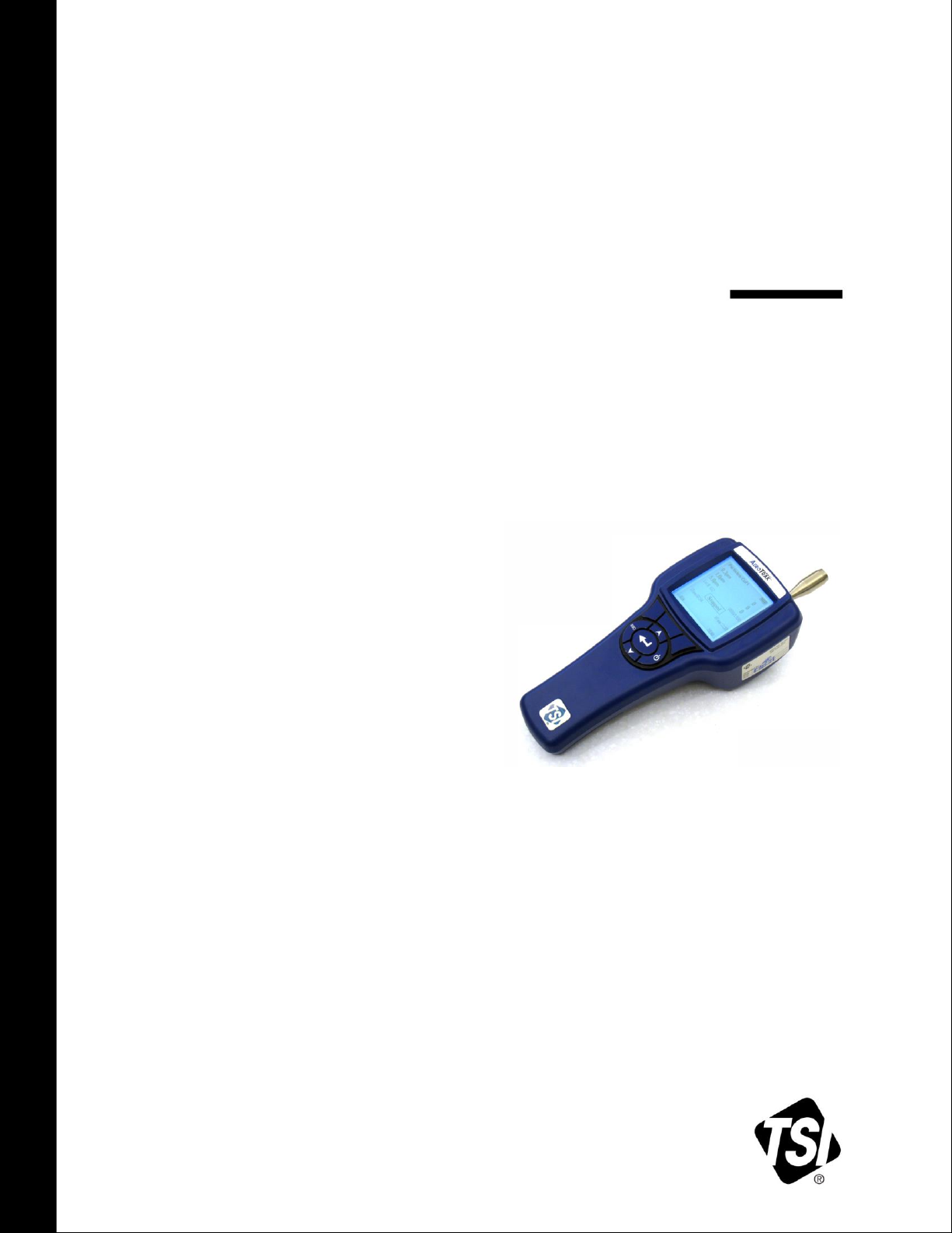
AEROTRAK®
HANDHELD AIRBORNE
PARTICLE COUNTER
MODEL 9303
OPERATION MANUAL
P/N 6002277, REVISION J
DECEMBER 2017
Page 2

Page 3

SHIP TO/MAIL TO:
TSI Incorporated
500 Cardigan Road
Shoreview, MN 55126-3996
USA
U.S.
Technical Support:
(800) 874-2811/(651) 490-2811
Fax:
(651) 490-3824
E-mail address:
answers@tsi.com
Website:
http://www.tsi.com
INTERNATIONAL
Technical Support:
(001 651) 490-2811
Fax:
(001 651) 490-3824
AEROTRAK®
HANDHELD AIRBORNE
PARTICLE COUNTER
MODEL 9303
OPERATION MANUAL
P/N 6002277, REVISION J
DECEMBER 2017
Page 4

Manual History
The following is a manual history of the AeroTrak® Handheld
Airborne Particle Counter, Model 9303 Operation Manual
(P/N 6002277).
Revision Date
A November 2008
B January 2009
C June 2009
D July 2010
E September 2010
F February 2011
G November 2012
H February 2016
J December 2017
ii
Page 5

Part Number
6002277 / Revision J / December 2017
Copyright
©TSI Incorporated / 2010-2017 / All rights reserved.
Address
TSI Incorporated / 500 Cardigan Road / Shoreview, MN 55126 / USA
E-mail Address
answers@tsi.com
Limitation of Warranty
and Liability
(effective April 2014)
Seller warrants the goods, excluding software, sold hereunder, under normal use and service
as described in the operator's manual, to be free from defects in workmanship and material
for 12 months, or if less, the length of time specified in the operator's manual, from the date
of shipment to the customer. This warranty period is inclusive of any statutory warranty. This
limited warranty is subject to the following exclusions and exceptions:
Warranty
a. Hot-wire or hot-film sensors used with research anemometers, and certain other components
when indicated in specifications, are warranted for 90 days from the date of shipment;
b. Pumps are warranted for hours of operation as set forth in product or operator’s manuals;
c. Parts repaired or replaced as a result of repair services are warranted to be free from defects
in workmanship and material, under normal use, for 90 days from the date of shipment;
d. Seller does not provide any warranty on finished goods manufactured by others or on any
fuses, batteries or other consumable materials. Only the original manufacturer's warranty
applies;
e. This warranty does not cover calibration requirements, and seller warrants only that the
instrument or product is properly calibrated at the time of its manufacture. Instruments
returned for calibration are not covered by this warranty;
f. This warranty is VOID if the instrument is opened by anyone other than a factory authorized
service center with the one exception where requirements set forth in the manual allow an
operator to replace consumables or perform recommended cleaning;
g. This warranty is VOID if the product has been misused, neglected, subjected to accidental
or intentional damage, or is not properly installed, maintained, or cleaned according to the
requirements of the manual. Unless specifically authorized in a separate writing by Seller,
Seller makes no warranty with respect to, and shall have no liability in connection with, goods
which are incorporated into other products or equipment, or which are modified by any person
other than Seller.
The foregoing is IN LIEU OF all other warranties and is subject to the LIMITATIONS stated
herein. NO OTHER EXPRESS OR IMPLIED WARRANTY OF FITNESS FOR PARTICULAR
PURPOSE OR MERCHANTABILITY IS MADE. WITH RESPECT TO SELLER’S BREACH
OF THE IMPLIED WARRANTY AGAINST INFRINGEMENT, SAID WARRANTY IS LIMITED
TO CLAIMS OF DIRECT INFRINGEMENT AND EXCLUDES CLAIMS OF CONTRIBUTORY
OR INDUCED INFRINGEMENTS. BUYER’S EXCLUSIVE REMEDY SHALL BE THE
RETURN OF THE PURCHASE PRICE DISCOUNTED FOR REASONABLE WEAR AND
TEAR OR AT SELLER’S OPTION REPLACEMENT OF THE GOODS WITH NONINFRINGING GOODS.
TO THE EXTENT PERMITTED BY LAW, THE EXCLUSIVE REMEDY OF THE USER OR
BUYER, AND THE LIMIT OF SELLER'S LIABILITY FOR ANY AND ALL LOSSES, INJURIES,
OR DAMAGES CONCERNING THE GOODS (INCLUDING CLAIMS BASED ON CONTRACT,
NEGLIGENCE, TORT, STRICT LIABILITY OR OTHERWISE) SHALL BE THE RETURN OF
GOODS TO SELLER AND THE REFUND OF THE PURCHASE PRICE, OR, AT THE
OPTION OF SELLER, THE REPAIR OR REPLACEMENT OF THE GOODS. IN THE CASE
OF SOFTWARE, SELLER WILL REPAIR OR REPLACE DEFECTIVE SOFTWARE OR IF
UNABLE TO DO SO, WILL REFUND THE PURCHASE PRICE OF THE SOFTWARE. IN NO
EVENT SHALL SELLER BE LIABLE FOR LOST PROFITS, BUSINESS INTERRUPTION, OR
ANY SPECIAL, INDIRECT, CONSEQUENTIAL OR INCIDENTAL DAMAGES. SELLER
SHALL NOT BE RESPONSIBLE FOR INSTALLATION, DISMANTLING OR
REINSTALLATION COSTS OR CHARGES. No Action, regardless of form, may be brought
against Seller more than 12 months after a cause of action has accrued. The goods returned
under warranty to Seller's factory shall be at Buyer's risk of loss, and will be returned, if at all,
at Seller's risk of loss.
iii
Page 6

Buyer and all users are deemed to have accepted this LIMITATION OF WARRANTY AND
Service Policy
Knowing that inoperative or defective instruments are as detrimental to TSI as they are to our
customers, our service policy is designed to give prompt attention to any problems. If any mal-
function is discovered, please contact your nearest sales office or representative, or call TSI’s
Customer Service department at 1-800-874-2811 (USA) or +001 (651) 490-2811
(International).
Trademarks
AeroTrak and TrakPro are trademarks of TSI Incorporated. TSI and the TSI logo are
registered trademarks of TSI Incorporated. Microsoft and Excel are registered trademarks of
Microsoft Corporation.
LIABILITY, which contains the complete and exclusive limited warranty of Seller. This
LIMITATION OF WARRANTY AND LIABILITY may not be amended, modified or its terms
waived, except by writing signed by an Officer of Seller.
iv AeroTrak® Handheld Airborne Particle Counters
Page 7

Contents
Manual History ............................................................................................ ii
Warranty ..................................................................................................... iii
Contents ...................................................................................................... v
Safety Information .................................................................................... vii
Laser Safety ......................................................................................... vii
Labels ................................................................................................... viii
Description of Caution/Warning Symbols ............................................. ix
Caution ............................................................................................... ix
Warning .............................................................................................. ix
Caution or Warning Symbols ............................................................. ix
Getting Help ........................................................................................... x
CHAPTER 1 Introduction and Unpacking ............................................. 1-1
Unpacking the AeroTrak Handheld Airborne Particle Counter ........... 1-1
Optional Accessories ....................................................................... 1-3
CHAPTER 2 Getting Started ................................................................... 2-1
Installing the Isokinetic Inlet ................................................................ 2-1
Providing Power .................................................................................. 2-2
Installing the Battery ........................................................................ 2-2
To Use AC Power ............................................................................ 2-3
Quick Start........................................................................................... 2-4
CHAPTER 3 Operation ............................................................................ 3-1
Warm-up Time .................................................................................... 3-2
Main Menu and Basic Operation ......................................................... 3-3
Main Menu ....................................................................................... 3-3
Basic Operation ............................................................................... 3-4
Settings Menu ..................................................................................... 3-6
Sample Menu ...................................................................................... 3-7
Buffer Menu ......................................................................................... 3-8
Utility Menu ......................................................................................... 3-9
CHAPTER 4 Data Handling ..................................................................... 4-1
USB Computer Communication .......................................................... 4-1
Installing Software ............................................................................... 4-1
CHAPTER 5 Maintenance ....................................................................... 5-1
Maintenance Schedule ........................................................................ 5-1
Zero Check .......................................................................................... 5-1
Cleaning the Instrument Enclosure ..................................................... 5-1
CHAPTER 6 Troubleshooting ................................................................. 6-1
v
Page 8

CHAPTER 7 Contacting Customer Service ........................................... 7-1
Technical Contacts .............................................................................. 7-1
International Contacts ...................................................................... 7-1
Returning the AeroTrak Handheld Airborne Particle Counter
for Service ........................................................................................ 7-3
APPENDIX A Specifications .................................................................. A-1
Compliance ........................................................................................ A-2
Dimensional Diagram ......................................................................... A-3
Index
vi AeroTrak® Handheld Airborne Particle Counters
Page 9
Laser Safety
W A R N I N G
The use of controls, adjustments, or procedures other than those
specified in this manual may result in exposure to hazardous optical
radiation.
Safety Information
This section gives instructions to promote safe and proper handling of the
AeroTrak® Handheld Airborne Particle Counters.
I M P O R T A N T
There are no user-serviceable parts inside the instrument. Refer all repair
and maintenance to a qualified factory-authorized technician. All
maintenance and repair information in this manual is included for use by a
qualified factory-authorized technician.
The Model 9303 Handheld Airborne Particle Counter is a Class I laser-
based instrument.
During normal operation, you will not be exposed to laser radiation.
Precaution should be taken to avoid exposure to hazardous radiation in
the form of intense, focused, invisible light.
Exposure to this light may cause blindness.
Take these precautions:
DO NOT remove any parts from the particle counter unless you are
specifically told to do so in this manual.
DO NOT remove the housing or covers. There are no user-serviceable
components inside the housing.
vii
Page 10
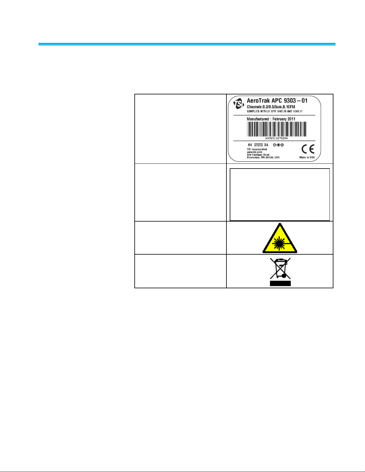
Labels
1. Serial number label
(back panel)
2. Laser radiation label
(internal)
DANGER!
INVISIBLE LASER RADIATION
WHEN OPEN. AVOID DIRECT
EXPOSURE TO BEAM
WARNING: NO USER SERVICABLE
PARTS INSIDE. REFER SERVICING
TO QUALIFIED PERSONNEL
3. Laser radiation symbol label
(internal)
4. European symbol for nondisposable item. Item must
be recycled.
Advisory labels and identification labels are attached to the outside of the
particle counter housing and to the optics housing on the inside of the
instrument.
viii AeroTrak® Handheld Airborne Particle Counters
Page 11
Description of Caution/ Warning Symbols
C a u t i o n
Failure to follow the procedures prescribed in this manual might result in
irreparable equipment damage. Important information about the operation
and maintenance of this instrument is included in this manual.
W A R N I N G
Warning means that unsafe use of the instrument could result in serious
injury to you or cause damage to the instrument. Follow the procedures
prescribed.
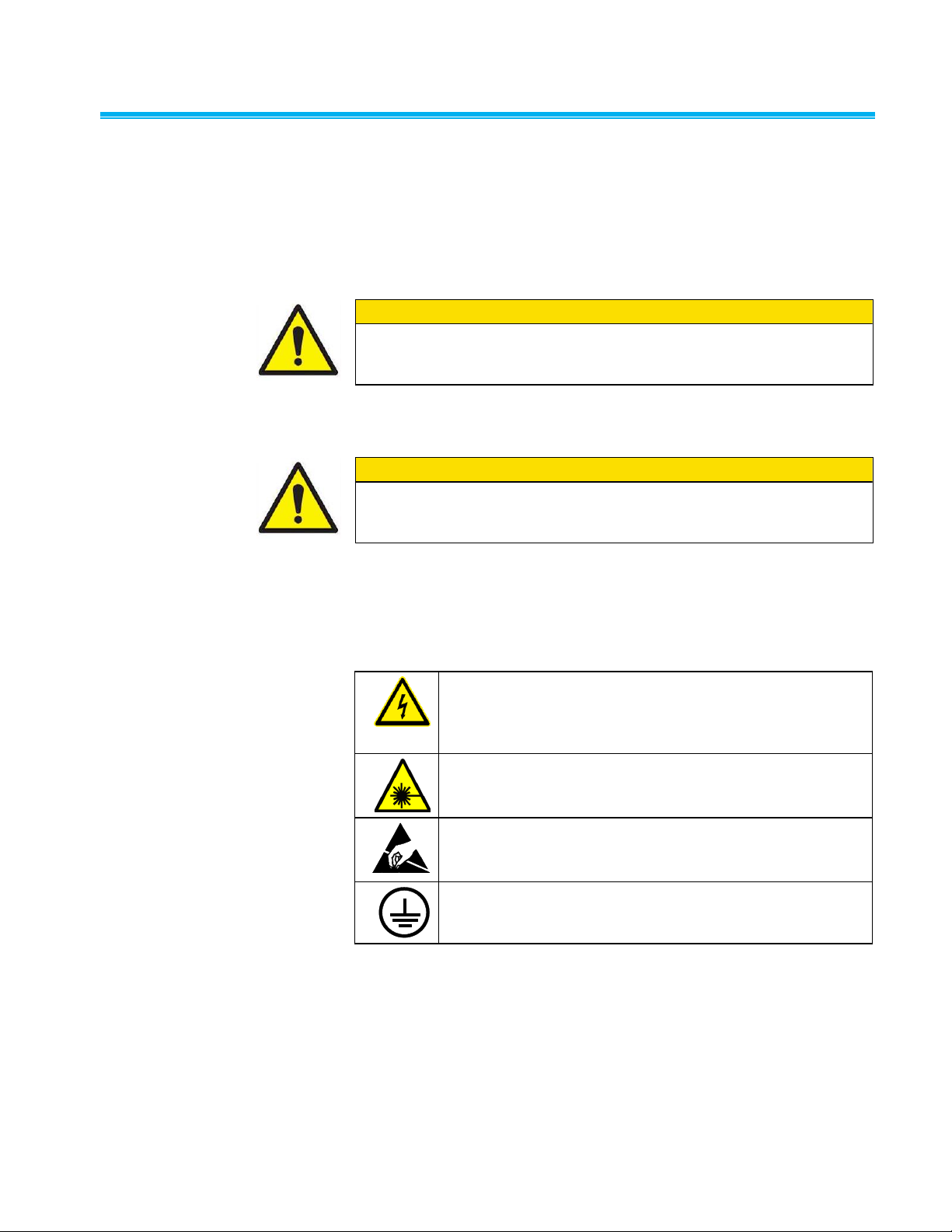
Warns that uninsulated voltage within the instrument may
have sufficient magnitude to cause electric shock.
Therefore, it is dangerous to make contact with any part
inside the instrument.
Warns that the instrument contains a laser and that
important information about its safe operation and
maintenance is included in the manual.
Warns that the instrument is susceptible to electro-static
dissipation (ESD) and ESD protection procedures should be
followed to avoid damage.
Indicates the connector is connected to earth ground and
cabinet ground.
Appropriate caution/warning statements are used throughout the manual
and on the instrument that require you to take cautionary measures when
working with the instrument.
Caution
Warning
Caution or Warning Symbols
The following symbols may accompany cautions and warnings to indicate
the nature and consequences of hazards:
Safety Information ix
Page 12

Getting Help
To obtain assistance with this product or to submit suggestions, please
contact Customer Service:
TSI Incorporated
500 Cardigan Road
Shoreview, MN 55126 U.S.A.
Fax: (651) 490-3824 (USA)
Fax: 001 651 490 3824 (International)
Telephone: 1-800-874-2811 (USA) or (651) 490-2811
International: 001 651 490-2811
E-mail Address: answers@tsi.com
Web site: www.tsi.com
x AeroTrak® Handheld Airborne Particle Counters
Page 13
Qty.
Item Description
Part/Model
Reference Picture
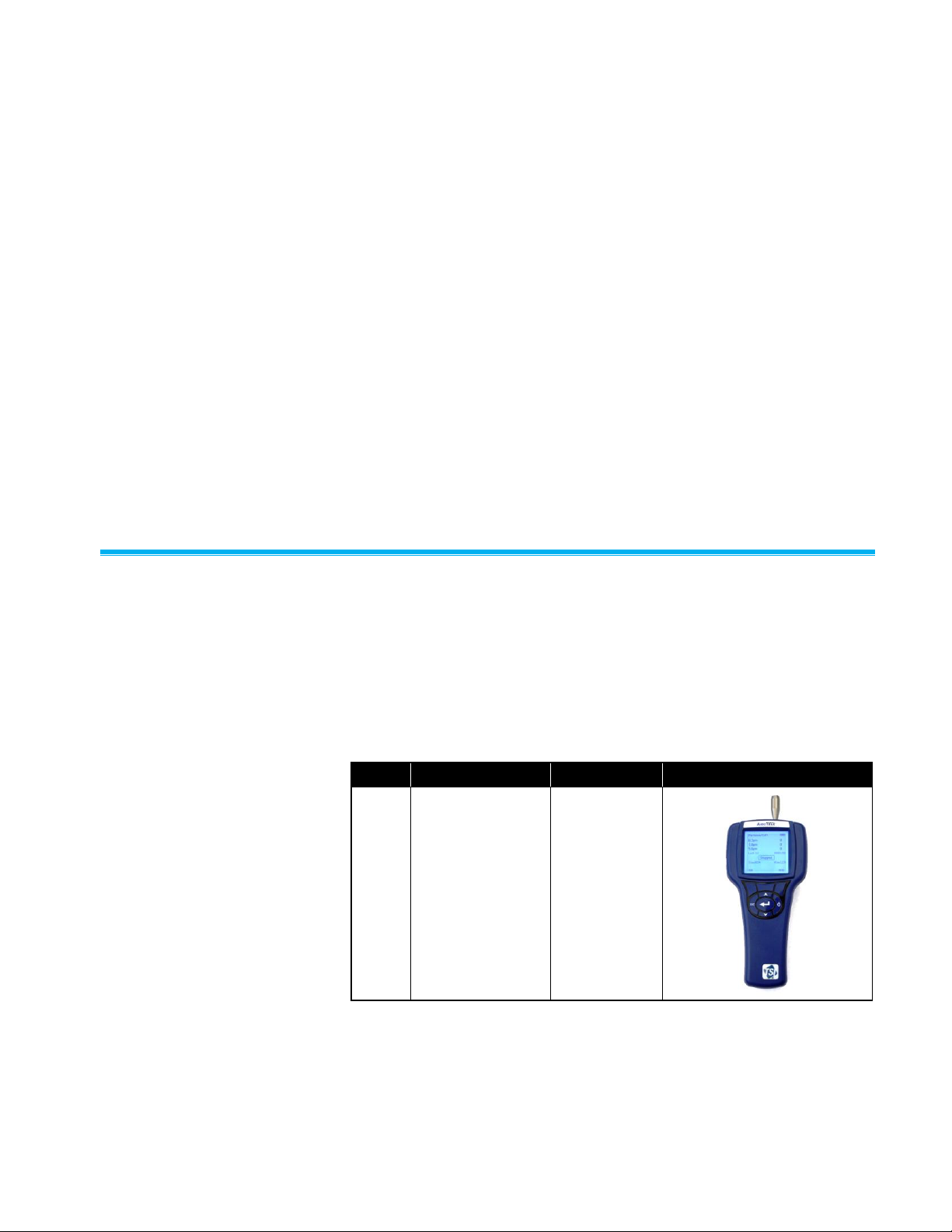
1
AeroTrak Airborne
Particle Counter
9303-01
C H A P T E R 1
Introduction and
Unpacking
The AeroTrak® Model 9303 Handheld Airborne Particle Counter (particle
counter) is a lightweight, handheld particle counter with a backlit LCD
display. It operates on the included lithium-ion battery or AC power.
This model has a 0.1 CFM (2.83 L/min) flow rate and counts in useradjustable bin sizes of 0.3, 0.5/1.0/2.0/2.5, and 5 microns (center channel
is selectable). Up to 1500 data sets can be stored and downloaded for
analysis and reporting using the TrakPro™ Lite utility included with
the device.
Unpacking the AeroTrak Handh e l d Airborne Particle Counter
Carefully unpack the AeroTrak Airborne Particle Counter from the shipping
container and verify that all the items shown in the photos below and listed
in the following tables are present. Contact TSI immediately if items are
missing or broken.
Model 9303 AeroTrak Airborne Particle Counter Parts List
1-1
Page 14
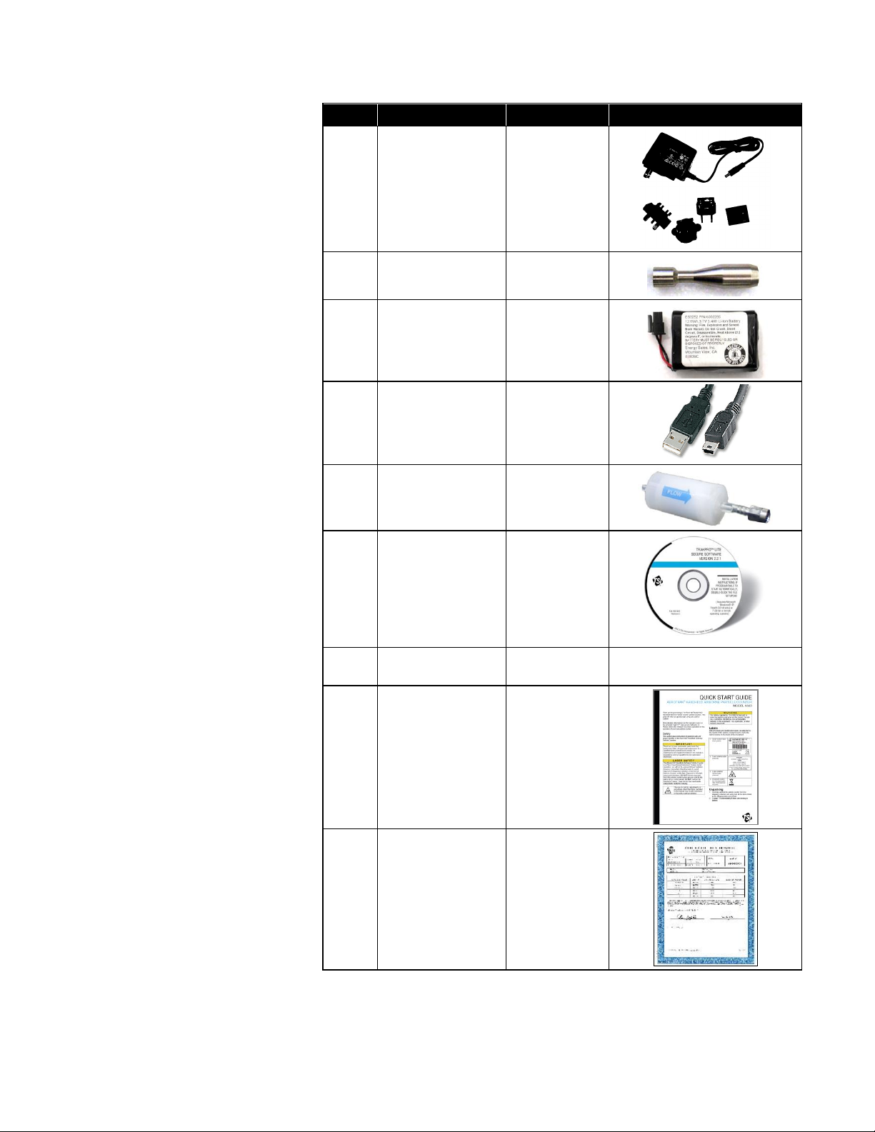
Qty.
Item Description
Part/Model
Reference Picture
1
AC power adapter
and countryspecific plugs
700021
1
Isokinetic inlet
700003
1
Battery Pack
700019
1
Computer cable,
USB A to mini-B
700036
1
HEPA zero filter
700005
1
TrakPro™ Lite
Secure Software
CD for 21 CFR
Part 11 compliant
data downloading
(includes
manuals)
7001901
1
Operation and
Service Manual
6002277
Included on TrakPro Lite
Secure Software CD
1
Quick Start Guide
6002238
1
Calibration
Certificate
N/A
1-2 AeroTrak® Handheld Airborne Particle Counters
Page 15
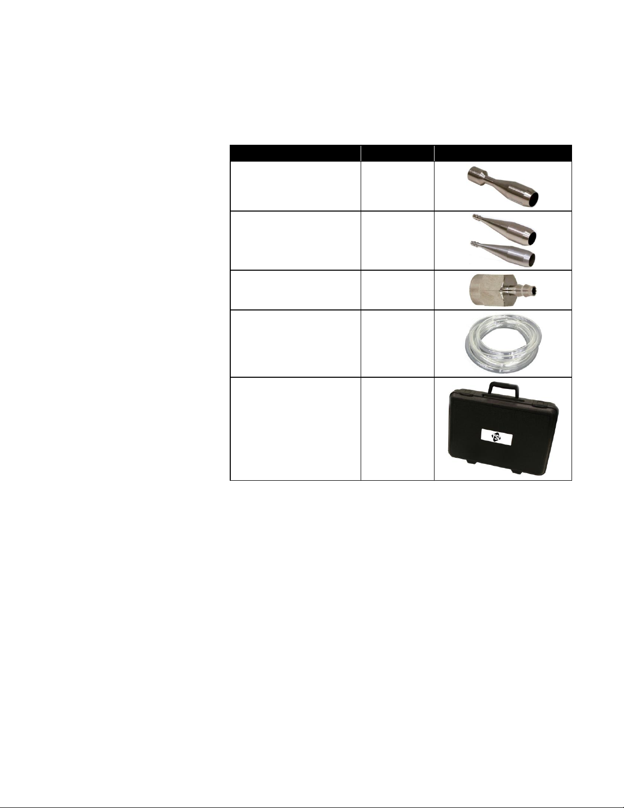
Optional Accessories
Item Description
Part/Model
Ref.
Stainless Steel Isokinetic
inlet
700004
Isokinetic probe (used
with tubing)
700001 AL
700002 SS
0.1 cfm Barb Inlet Fitting
700020
Tubing, Superthane
1/8-inch ID x ¼-inch OD,
Clear 100 Ft Box
700009
Light Duty Carry Case
700115
The following photo and table list optional accessories. If you ordered
optional accessories, make certain they have been received and are in
working order.
Introduction and Unpacking 1-3
Page 16

(This page intentionally left blank)
1-4 AeroTrak® Handheld Airborne Particle Counters
Page 17

C H A P T E R 2
Getting Started
This chapter provides information to help you use the Model 9303
including:
Installing the Isokinetic Inlet
Providing Power
Quick Start
Installing the Isokinet i c Inlet
The Isokinetic Inlet smoothly accelerates air into the inlet of the instrument.
To install, simply screw the probe directly onto the threaded inlet nozzle.
Installing an Isokinetic Inlet
2-1
Page 18

Providing Power
W A R N I N G
The battery supplied by TSI (700019) has built in protection against
explosion and fire hazard. Do not use a substitute.
W A R N I N G
Do not use non-rechargeable batteries in this instrument. Fire,
explosions, or other hazards may result.
The Model 9303 may be powered using its internal rechargeable lithiumion battery or through an AC power cord.
Notes:
When using AC power, the battery is charging when the red LED next
to the power connector is on.
Removing/changing the lithium-ion battery or disconnecting AC power
does not cause the loss of data.
You should fully charge the battery before use.
Installing the Battery
1. The battery is shipped separately and has to be installed before use.
2. Remove the battery cover on the back side of the handle with a small,
flat-blade screwdriver.
3. Connect the battery to the socket as shown below.
4. Insert the battery with the connector at the top and replace the battery
cover. Make sure all wires are inside and not pinched in the cover. Do
not over-tighten the screw.
5. Fully charge the battery before use.
2-2 AeroTrak® Handheld Airborne Particle Counters
Page 19

To Use AC Power
1. Remove the AC transformer parts from their package and identify the
appropriate plug for your needs. Plugs are available for all common
countries.
2. Remove the insert from transformer using the slide lock and tilt the
insert out.
3. Tilt the appropriate plug into the transformer receptacle.
4. Make sure it locks into place.
Getting Started 2-3
Page 20

Quick Start
5. Plug the DC end of the transformer cord into the counter.
6. Plug the AC end of the transformer cord into an AC outlet.
7. The Power LED lights when the battery is charging. When the Power
LED is off, the battery is fully charged.
8. When the battery is charged, unplug the power supply.
The best way to quickly get started is to refer to the printed “Quick Start
Guide” included with your instrument. It will help you to quickly set up the
instrument and begin sampling. Refer to the sections below for more
detailed information on configuring and running the instrument.
2-4 AeroTrak® Handheld Airborne Particle Counters
Page 21

Backlit
Display
Key Pad
Isokinetic
Inlet
Power
LED
DC
Adapter
Socket
USB Port
Right Soft
Key
Left Soft
Key
Up
On/Off
Enter
Return
to
Previous
Screen
Down
C H A P T E R 3
Operation
The Model 9303 is controlled using the integral keys and the backlit
display.
To turn on the instrument, press the On/Off key. A splash screen will
appear for three seconds, displaying the TSI logo, model number, serial
number, and firmware version number (see below).
3-1
Page 22

Particle Counter
MODEL:
9303-01
SERIAL:
93030837003
REV:
2.10
Splash Screen
0.3µm
0
1.0µm
0
5.0µm
0
Loc # 001
0002/1500
Stopped
STime 01:00
HTime 00:05
RUN
MENU
The instrument is ready for operation when the default screen (shown
below) appears.
Default Screen
Note: To turn off the instrument, press and hold the On/Off key for
5 seconds. The instrument turns off.
Warm-up Time
3-2 AeroTrak® Handheld Airborne Particle Counters
An initial warm-up period of 15 minutes is recommended before sampling
with the Model 9303. The warm-up period allows time for the optics to
reach a steady-state temperature. This will result in more repeatable
results. Neglecting the warm-up time may result in an overestimation of
particle size (approximately 10 percent). Neglecting the warm-up time will
not have a significant effect on particle concentration; therefore, a zero
count can still be performed without waiting for the warm-up period.
Page 23

Main Menu and Basic Op e ration
MAIN MENU
Settings
Sample Menu
Buffer Menu
Utility Menu
Menu
Description
Settings
Set language, time and date, time and day format, and
screen settings.
Sample
Set sample mode, cycle mode, sample time, hold time,
cycle count, sample units, and channel 2 size.
Buffer
View the number of records stored in the Model 9303,
display buffer records, and clear the buffer.
Utility
Adjust the pump speed, turn data logging on and off, and
select the sampling location.
Press Menu on the Default Screen to display the Main Menu.
Main Menu
Main Menu
From the Main Menu you can select other menus:
Each of these menus is described in the remainder of this chapter.
Operation 3-3
Page 24

Basic Operation
Right Soft
Key
Left Soft
Key
Up
On/Off
Enter
Return
to
Previous
Screen
Down
This section explains the basic operation for using the keypad and starting
sampling.
Using the Keypad
Use the up and down keys to highlight a menu or a menu option then:
If left and right arrows (< >) appear at the bottom of the screen, use the
left and right soft keys to select the option you want. Generally, there
will be only 2 or 3 options. Soft keys change function depending on the
display above them. For instance, in the picture above, the left soft key
is labeled RUN and the right soft key is labeled MENU. The center soft
key is not currently used.
If no arrows appear at the bottom, press the Enter key to bring up a
secondary window from which you can make a selection or modify
a setting.
Use the up and down keys to perform operations such as increasing a
value. Use the right soft key and left soft keys to move right and left.
The ESC key always brings you back to the previous screen.
3-4 AeroTrak® Handheld Airborne Particle Counters
Page 25

Start Sampling
0.3µm
19031
1.0µm
8186
5.0µm
4671
Loc# 001
0026/1500
Sampling
Stime 00:45
STOP
0.3µm
35800
1.0µm
14154
5.0µm
8237
Loc# 001
0026/1500
Stopped
Stime 01:00
HTime 00:05
RUN
MENU
To start sampling, press the left soft key (below “RUN”). The Model 9303
begins collecting samples immediately if set to manual mode or according
to the parameters you have set for automatic mode.
To stop sampling at any time, press the STOP soft key.
Operation 3-5
Page 26

Settings Menu
SETTINGS MENU
Language
English
Set Time
2:41:55 PM
Set Date
09/12/08
Time Format
12 hr
Date Format
MMDDYY
Backlight
On
<
>
Option
Description
Parameters
Language
Use < and > to set the
language in which
information is displayed.
English
(other languages may be
offered)
Set Time
Press the Enter key to go to
a secondary screen where
you can set the current time.
Hours, minutes, seconds
Set Date
Press the Enter key to go to
a secondary screen where
you can set the current date.
Day, month, year
Time Format
Use < and > to set the time
format in which time is
displayed (and saved in the
sample records).
12 hr; 24 hr
Date Formats
Use < and > to set the date
format in which the date is
displayed (and saved in the
sample records).
DD/MM/YY; MM/DD/YY
Backlight
Use < and > to set whether
the backlight on the display
is on or off.
Note that battery life is
approximately 15% less with
the backlight enabled.
On – backlight is always on
Off – backlight is always off
The Settings Menu lets you set language (supported in future), current time
and date, select the time and day format, and set certain screen settings.
Settings Menu
The following table describes the options of this menu and the parameters
you can set.
3-6 AeroTrak® Handheld Airborne Particle Counters
Page 27

Sample Menu
SAMPLE MENU
Sample Mode
COUNTS
Cycle Mode
AUTO
Sample Time
01:00
Hold Time
00:30
Cycle Count
010
Sample Units
LITER
Chan 2 Size
0.5µm
<
>
Option
Description
Parameters
Sample Mode
Use < and > to set
the sampling mode.
Concentration (see note below);
counts
Cycle Mode
Use < and > to set
the sampling mode.
Manual – the counter will start
when the RUN soft key is pressed
and stop only when the STOP soft
key is pressed.
Auto – the counter will start when
the RUN soft key is pressed and
turn on and off automatically to
follow the sample time, hold time
and cycle count parameters below.
Sample Time
Press the Enter key
to go to a secondary
screen where you
can set the sample
time.
Minutes and seconds up to 99:59
(see note below)
Hold Time
Press the Enter key
to go to a secondary
screen where you
can set the time
between samples.
Minutes and seconds up to 99:59
Cycle Count
Press the Enter key
to go to a secondary
screen where you
can set the number
of samples to take.
1 to 999
The Sample Menu sets sample mode, cycle mode, sample time, hold time,
cycle count, sample units, and channel 2 size.
Sample Menu
The following table describes the options of this menu and the parameters
you can set.
Operation 3-7
Page 28

Option
Description
Parameters
Sample Units
Use < and > to set
the sampling units.
Liter; cubic feet
Channel 2
Size
Use < and > to set
the bin size for
channel 2. (This is
the only channel that
can be set to more
than one value.)
0.5, 1.0, 2.0, 2.5 µm
N o t e
When concentration sample mode is used with short sample times
(less than 30 seconds), the concentration may not be accurate due to
the poor counting and timing statistics associated with a short sample.
BUFFER MENU
# of Records
0035/1500
Show Buffer Record
Clear Buffer
Option
Description
Parameters
# of Records
Shows the number or sample records
stored in the Model 9303.
None
Show Buffer
Record
Press the Enter key to go to a
secondary screen where you can
select the record (by sample number)
of the record you want to view.
Any record
number (up to
1500)
Clear Buffer
Press the Enter key to clear all
samples in the buffer. You will be
asked to confirm your request.
None
Buffer Menu
The Buffer Menu lets you view the number of records stored in the
Model 9303, display buffer records, and clear the buffer.
Buffer Menu
The following table describes the options of this menu and the parameters
you can set.
3-8 AeroTrak® Handheld Airborne Particle Counters
Page 29

BUFFER RECORD
Record#:
0313
Date:
12/27/08
Time:
05:50:45
0.3µm
000566473
0.5µm
000534571
5.0µm
000072056
Location:
111
Sample Time:
01:00
Hold Time:
00:00
<
>
N o t e
If the buffer is filled to its capacity of 1500 records, the instrument will
continue to count and save records but the next record after 1500 will
be saved in record number 1, then 2, etc. This way the most recent
1500 records are always preserved.
UTILITY MENU
Pump Speed
099
Data Logging
ON
Location
120
Utility Menu
Example of a Buffer Record
Use the < and > softkeys to scroll through the records, Enter to go back
one screen and ESC to go back to the Buffer Menu.
The Utility Menu lets you adjust the pump speed, turn data logging on and
off, and select the sampling location.
Utility Menu
Operation 3-9
Page 30

The following table describes the options of this menu and the parameters
C a u t i o n
If you turn Data Logging off, no data will be saved to the buffer.
Option
Description
Parameters
Pump Speed
Press the Enter key to go to a
secondary screen where you can
increase or decrease the pump speed.
(The pump may slow down with age,
or it may be necessary to increase the
speed if there are flow restrictions –
such as long tubing). Use a flowmeter
to check the flow when taking critical
measurements, and adjust the pump
speed as necessary.
0 to 255
Data Logging
Use < and > to turn data logging on
and off.
ON; OFF
Locations
Press the Enter key to go to a
secondary screen where you can
select a location number.
0 to 250
you can set.
3-10 AeroTrak® Handheld Airborne Particle Counters
Page 31

C H A P T E R 4
Data Handling
USB Computer Commun i cation
Mini USB Port
The Model 9303 is equipped with a USB-compatible cable for uploading
and downloading information to a PC. The cable plugs into the left side of
the instrument as shown above.
Installing Software
Refer to the TrakPro™ Lite Secure Software User’s Guide (P/N 6004404)
on CD (P/N 7001901) for installation instructions.
4-1
Page 32

(This page intentionally left blank)
4-2 AeroTrak® Handheld Airborne Particle Counters
Page 33

N o t e
There are no user-serviceable parts inside this instrument. Opening the
instrument case may void the warranty. TSI recommends that you return
the AeroTrak Airborne Particle Counter to the factory for any required
maintenance or service not described in this manual.
Item
Frequency
Zero check
Daily (or as defined by application).
Factory cleaning and calibration
Annually.
Cleaning the instrument enclosure
As needed.
C H A P T E R 5
Maintenance
Maintenance Schedule
TSI recommends annual factory cleaning and calibration for the AeroTrak
Airborne Particle Counter. See Chapter 7, "Contacting Customer Service"
for service/calibration.
Recommended Field Maintenance Schedule
Zero Check
The zero check ensures that the instrument is properly assembled and free
from leaks, residual particles and electronic noise.
Cleaning the Instrum e n t Enclosure
To clean the enclosure, dampen a lint-free cloth and gently wipe the
surface until surface contamination is removed.
5-1
Page 34

(This page intentionally left blank)
5-2 AeroTrak® Handheld Airborne Particle Counters
Page 35

Symptom
Possible Cause
Corrective Action
Counts are too low.
Instrument is being
operated outside
temperature or relative
humidity
specifications.
Operate instrument within
specifications.
Internal parts have
been damaged
because instrument
was stored at a
temperature greater
than 122 °F (50 °C) or
shipped with battery
installed and turned
on causing
excessive heat.
Return to factory or
factory authorized service
centers for service.
Instrument has
contamination on the
optics due to
condensation or
excessive loading.
Return to factory or
factory authorized service
centers for service.
Laser or pump is
damaged.
Return to factory or
factory authorized service
centers for service.
Unit is due for
calibration.
Return to factory or
factory authorized service
centers for service.
Instrument does not
turn on.
On/off switch is not
being pressed
properly.
Battery is dead.
AC cord is not
plugged into unit.
Press and hold on/off
switch for one second.
Recharge battery or
connect to AC power.
Connect AC cord.
C H A P T E R 6
Troubleshooting
6-1
Page 36

Symptom
Possible Cause
Corrective Action
Instrument does not
meet zero count
specification
(<1 particle/5 min).
HEPA filter is not
connected properly
and room air is leaking
into the HEPA filter
assembly.
Check that the HEPA
filter has been tightly
connected to the inlet.
Check that rubber O-ring
(black) on the inlet is
in place.
Residual particles
from previous samples
are shedding off
internal parts and into
the optics.
Purge instrument by
running the instrument for
10 to 15 minutes or
longer before attempting
zero count test.
The filter assembly or
inlet are dirty or
contaminated with
particles.
Clean the HEPA filter
fitting or run an extended
test to clean out particles.
An internal component
has been damaged
due to operation
outside of temperature
specifications or one
or more excessive
bumps or jolts, and
electronic noise is
inducing false counts.
Return to factory or
factory authorized service
centers for service.
A leak has developed
in the aerosol flow
path.
Return to factory or
factory authorized service
centers for service.
Internal optics have
become dirty.
Return to factory or
factory authorized service
centers for service.
Battery does not
charge
The battery may not
be installed or is
disconnected.
Check battery.
Low Battery Indicator
Low battery.
Recharge battery or
connect AC cord
Software doesn’t
connect to unit
No connection or
power.
Check that USB is
connected to instrument
and instrument is
turned on.
Unit is running a
sample or in a sub
menu.
Stop sample and make
sure screen shows main
view.
6-2 AeroTrak® Handheld Airborne Particle Counters
Page 37

C H A P T E R 7
Contacting Customer
Service
This chapter gives directions for contacting people at TSI Incorporated for
technical information and directions for returning the AeroTrak® Handheld
Airborne Particle Counter for service.
Technical Contacts
If you have any difficulty setting up or operating the AeroTrak Model
9303, or if you have technical or application questions about this
system, contact an applications engineer at TSI Incorporated, 1-800874-2811 (USA) or (651) 490-2811 or e-mail
technical.service@tsi.com.
If the AeroTrak Model 9303 does not operate properly, or if you are
returning the instrument for service, visit our website at
http://rma.tsi.com, or contact TSI Customer Service at 1-800-874-2811
(USA) or (651) 490-2811.
International Contacts
Service
TSI Instruments Singapore Pte Ltd
150 Kampong Ampat
#05-05 KA Centre
Singapore 368324
Telephone: +65 6595-6388
Fax: +65 6595-6399
E-mail: tsi-singapore@tsi.com
TSI Instrument (Beijing) Co., Ltd.
Unit 1201, Pan-Pacific Plaza
No. 12 A, Zhongguancun South Avenue
Haidian District, Beijing, 100181
CHINA
Telephone: +86-10-8219 7688
Fax: +86-10-8219 7699
E-mail: tsibeijing@tsi.com
7-1
Page 38

TSI Instruments Ltd.
Stirling Road
Cressex Business Park
High Wycombe, Bucks
HP12 3ST
UNITED KINGDOM
Telephone: +44 (0) 149 4 459200
Fax: +44 (0) 149 4 459700
E-mail: tsiuk@tsi.com
Technical Support
TSI Instruments Singapore Pte Ltd
150 Kampong Ampat
#05-05 KA Centre
Singapore 368324
Telephone: +65 6595-6388
Fax: +65 6595-6399
E-mail: tsi-singapore@tsi.com
TSI Instrument (Beijing) Co., Ltd.
Unit 1201, Pan-Pacific Plaza
No. 12 A, Zhongguancun South Avenue
Haidian District, Beijing, 100181
CHINA
Telephone: +86-10-8219 7688
Fax: +86-10-8219 7699
E-mail: tsibeijing@tsi.com
TSI GmbH
Neuköllner Strasse 4
52068 Aachen
GERMANY
Telephone: +49 241-52303-0
Fax: +49 241-52303-49
E-mail: tsigmbh@tsi.com
TSI Instruments Ltd.
Stirling Road
Cressex Business Park
High Wycombe, Bucks
HP12 3ST
UNITED KINGDOM
Telephone: +44 (0) 149 4 459200
Fax: +44 (0) 149 4 459700
E-mail: tsiuk@tsi.com
Web: www.tsiinc.co.uk
7-2 AeroTrak® Handheld Airborne Particle Counters
Page 39

TSI France Inc.
Hotel technologique
BP 100
Technopôle de Château-Gombert
13382 Marseille cedex 13
FRANCE
Telephone: + 33 (0)1 41 19 21 99
Fax: + 33 (0)1 41 19 21 96
E-mail: tsifrance@tsi.com
Web: www.tsiinc.fr
Returning the AeroTrak Handhe l d Airborne Particle Counter for S e r vice
Visit our website at http://rma.tsi.com or call TSI at 1-800-874-2811 (USA)
or (651) 490-2811 for specific return instructions. Customer Service will
need this information when you call:
The instrument model number
The instrument serial number
A purchase order number (unless under warranty)
A billing address
A shipping address
Use the original packing material to return the instrument to TSI. If you no
longer have the original packing material, seal off any ports to prevent
debris from entering the instrument and ensure that the display and the
connectors on the instrument front and back panels are protected.
Contacting Customer Service 7-3
Page 40

(This page intentionally left blank)
7-4 AeroTrak® Handheld Airborne Particle Counters
Page 41

Size Range
0.3 to 25 µm
Channel Sizes
0.3 µm and 5.0 µm fixed; 0.5, 1.0, 2.0, or 2.5 µm
selectable middle channel.
Counting Efficiency
50% at 0.3 µm; 100% for particles > 0.45 µm
(per ISO 21501-4 and JIS)
Concentration Limits
2,000,000 particles/ft3 at 5% coincidence loss
Light Source
Long life laser diode
Zero Count Level
<1 count / 5 minutes (per ISO 21501-4 and
JIS B9921)
Flow Rate
0.1 CFM (2.83 L/min)
Calibration
NIST traceable with TSI calibration system
Sample Probe/Tubing
Isokinetic sampling probe
Sampling Modes
Manual and automatic
Sampling Time
1 second to 99 minutes 59 seconds
Sampling Frequency
1 to 999 cycles or continuous
Exhaust
Internal HEPA filter
Vacuum Source
Internal pump
Communication Mode
USB serial output
Data Storage
1,500 sample records
Status Indicators
Low battery and service
Display
3.2-in. (8.1 cm) 160 x 160 monochrome LCD
External Surface
High impact injection molded plastic
AC Power (power to
AC adapter)
110 to 240 VAC 50-60 Hz Universal in-line
power supply with country specific plugs
DC Power (power to
instrument)
9 VDC @ 1.5 A
Battery
Rechargeable Li-Ion
Battery Life
Up to 4.5 hours of continuous use
Recharge Time
< 3 hours
Dimensions (L x W x H)
9.1 x 6.3 x 2.4 in. (23 x 11 x 6.2 cm) (without
isokinetic inlet)
A P P E N D I X A
Specifications
All specifications meet or exceed JIS B9921. They are subject to change
without notice.
A-1
Page 42

Weight
1.3 lbs (0.58 kg) with battery
Standards
CE, JIS B9921, ISO 21501-4
Warranty
1 year (extended warranties available)
Operating Conditions
41° to 95°F (5° to 35°C) temperature and 20% to
95% non-condensing relative humidity
Storage Conditions
32° to 122°F (0° to 50°C) temperature and up to
98% non-condensing relative humidity
Included Accessories
Operating manual on CD, power supply, battery,
isokinetic inlet, purge filter, USB cable and
TrakPro™ Lite data download software
Optional Accessories
Spare battery, isokinetic probe, sample tubing
and carrying case
Compliance
CE Marking
EN61326 / EN 55011, Class BA: Radiated Emissions
EN61326 / EN 55011, Class BA: Conducted Emissions
EN61000-3-2: Harmonics
EN61000-3-3: Voltage Fluctuations
EN61000-4-2: Electrostatic Discharge Immunity
EN61000-4-3: Electromagnetic Field Immunity
EN61000-4-4: Burst Immunity
EN61000-4-6: Conducted PS Immunity
EN61000-4-5: Surge Immunity
EN61000-4-8: Rated Power-Frequency Field Immunity
EN61000-4-11: Voltage Dips\Short Interruptions
Immunity
RoHS Marking
Yes
Laser Safety
Complies with 21 CFR 1040.10 and 1040.11
A-2 AeroTrak® Handheld Airborne Particle Counters
Page 43

Dimensional Diagram
Specifications A-3
Page 44

(This page intentionally left blank)
A-4 AeroTrak® Handheld Airborne Particle Counters
Page 45

Index
#
# of records, 3-9
A
AC power, A-1
using, 2-3
AC power adapter, 1-2
accessories, A-2
optional, 1-3, A-2
B
backlight, 3-6
backlit display, 3-1
barb inlet fitting, 1-3
battery, A-1
indicator low, 6-2
installation, 2-2
life, A-1
not charging, 6-2
recharge time, A-1
battery pack, 1-2
buffer, 3-3
buffer menu, 3-8
# of records, 3-9
clear buffer, 3-9
show buffer record, 3-9
buffer record, 3-9
C
calibration, A-1
calibration certificate, 1-2
caution
description, ix
symbol, ix
turning data logging off, 3-10
CE marking, A-2
channel 2 size, 3-8
channel size, A-1
cleaning instrument enclosure, 5-1
clear buffer, 3-9
communication mode, A-1
compliance, A-2
computer cable, 1-2
concentration limits, A-1
contacting TSI, 7-1
email address, iii
counting efficiency, A-1
counts too low, 6-1
customer service, 7-1
cycle count, 3-8
cycle mode, 3-7
D
daily zero check, 5-1
data handling, 4-1
data logging, 3-10
data storage, A-1
date formats, 3-6
DC adapter socket, 3-1
DC power, A-1
default screen, 3-2
dimensions, A-1, A-3
display, A-1
E
ESD protection symbol, ix
external surface, A-1
F
factory cleaning, 5-1
flow rate, A-1
G
getting help, x
getting started, 2-1
H
help, x, 7-1
HEPA zero filter, 1-2
hold time, 3-7
I–J
installation
battery, 2-2
isokinetic inlet, 2-1
software, 4-1
instrument does not meet zero count
specification, 6-2
instrument does not turn on, 6-1
introduction, 1-1
isokinetic inlet, 1-2, 3-1
installation, 2-1
isokinetic probe, 1-3
K
key pad, 3-1
keypad
using, 3-4
L
label
laser radiation, viii
laser safety, viii
serial number, viii
language, 3-6
laser radiation label, viii
laser safety, vii, A-2
laser symbol label, viii
light duty carry case, 1-3
light source, A-1
locations, 3-10
M–N
main menu, 3-3
maintenance, 5-1
cleaning instrument enclosure, 5-1
daily zero check, 5-1
factory cleaning, 5-1
schedule, 5-1
manual history, ii
mini USB port, 4-1
O
operating conditions, A-2
operation, 3-1
basic, 3-3, 3-4
optional accessories, 1-3
P–Q
packing instructions, 7-3
parts list, 1-1
power, 2-2, A-1
using, 2-3
power LED, 3-1
pump speed, 3-10
R
returning for service, 7-3
RoHS marking, A-2
S
safety, vii
sample, 3-3
sample menu, 3-7
channel 2 size, 3-8
cycle count, 3-8
cycle mode, 3-7
hold time, 3-7
sample mode, 3-7
sample time, 3-7
sample units, 3-8
Index-1
Page 46

sample mode, 3-7
sample output, A-1
sample probe/tubing, A-1
sample time, 3-7
sample units, 3-8
sampling
start, 3-5
stop, 3-5
sampling frequency, A-1
sampling mode, A-1
sampling time, A-1
serial number label, viii
service
returning, 7-3
set date, 3-6
set time, 3-6
settings, 3-3
settings menu, 3-6
show buffer record, 3-9
size range, A-1
software
installation, 4-1
troubleshooting, 6-2
specifications, A-1
splash screen, 3-2
stainless steel isokinetic inlet, 1-3
standards, A-2
start menu
backlight, 3-6
date formats, 3-6
language, 3-6
set date, 3-6
set time, 3-6
time format, 3-6
start sampling, 3-5
status indicators, A-1
stop sampling, 3-5
storage conditions, A-2
superthane tubing, 1-3
W–X–Y
warm-up time, 3-2
warning
description, ix, 2-2
symbol, ix
warranty, iii, A-2
weight, A-1
Z
zero check, 5-1
zero count level, A-1
T
technical contacts, 7-1
time format, 3-6
troubleshooting, 6-1
U
unpacking, 1-1
USB computer communication, 4-1
USB port, 3-1
using keypad, 3-4
utility, 3-3
utility menu, 3-10
data logging, 3-10
locations, 3-10
pump speed, 3-10
V
vacuum source, A-1
Index-2 AeroTrak® Handheld Airborne Particle Counters
Page 47

USA Tel: +1 800 874 2811
UK Tel: +44 149 4 459200
France Tel: +33 1 41 19 21 99
Germany Tel: +49 241 523030
India Tel: +91 80 67877200
China Tel: +86 10 8219 7688
Singapore Tel: +65 6595 6388
TSI Incorporated – Visit our website www.tsi.com for more information.
P/N 6002277 Rev J ©2017 TSI Incorporated Printed in U.S.A.
 Loading...