

Page 1
ENERGY AND COMFORT
Ventilation Testing/Balancing
ACCUBALANCE®
Air Capture Hood
Model 8371
Operation and Service Manual
1980335, Revision D
June 2009
Page 2

Copyright©
TSI Incorporated / October 2002-2009 / All rights reserved.
Address
TSI Incorporated / 500 Cardigan Road / St. Paul, MN 55126 / USA
Fax No.
(651) 490-3824
LIMITATION OF WARRANTY AND LIABILITY (effective July 2000)
Seller warrants the goods sold hereunder, under normal use and service as described in the
operator's manual, shall be free from defects in workmanship and material for twenty-four (24)
months, or the length of time specified in the operator's manual, from the date of shipment to the
customer. This warranty period is inclusive of any statutory warranty. This limited warranty is
subject to the following exclusions:
a. Hot-wire or hot-film sensors used with research anemometers, and certain other
components when indicated in specifications, are warranted for 90 days from the date of
shipment.
b. Parts repaired or replaced as a result of repair services are warranted to be free from
defects in workmanship and material, under normal use, for 90 days from the date of
shipment.
c. Seller does not provide any warranty on finished goods manufactured by others or on any
fuses, batteries or other consumable materials. Only the original manufacturer's warranty
applies.
d. Unless specifically authorized in a separate writing by Seller, Seller makes no warranty
with respect to, and shall have no liability in connection with, goods which are
incorporated into other products or equipment, or which are modified by any person other
than Seller.
The foregoing is IN LIEU OF all other warranties and is subject to the LIMITATIONS stated
herein. NO OTHER EXPRESS OR IMPLIED WARRANTY OF FITNESS FOR
PARTICULAR PURPOSE OR MERCHANTABILITY IS MADE.
TO THE EXTENT PERMITTED BY LAW, THE EXCLUSIVE REMEDY OF THE USER OR BUYER,
AND THE LIMIT OF SELLER'S LIABILITY FOR ANY AND ALL LOSSES, INJURIES, OR DAMAGES
CONCERNING THE GOODS (INCLUDING CLAIMS BASED ON CONTRACT, NEGLIGENCE, TORT,
STRICT LIABILITY OR OTHERWISE) SHALL BE THE RETURN OF GOODS TO SELLER AND THE
REFUND OF THE PURCHASE PRICE, OR, AT THE OPTION OF SELLER, THE REPAIR OR
REPLACEMENT OF THE GOODS. IN NO EVENT SHALL SELLER BE LIABLE FOR ANY SPECIAL,
CONSEQUENTIAL OR INCIDENTAL DAMAGES. SELLER SHALL NOT BE RESPONSIBLE FOR
INSTALLATION, DISMANTLING OR REINSTALLATION COSTS OR CHARGES. No Action,
regardless of form, may be brought against Seller more than 12 months after a cause of action has accrued.
The goods returned under warranty to Seller's factory shall be at Buyer's risk of loss, and will be returned, if
at all, at Seller's risk of loss.
Buyer and all users are deemed to have accepted this LIMITATION OF WARRANTY AND
LIABILITY, which contains the complete and exclusive limited warranty of Seller. This
LIMITATION OF WARRANTY AND LIABILITY may not be amended, modified or its terms
waived, except by writing signed by an Officer of Seller.
Service Policy
Knowing that inoperative or defective instruments are as detrimental to TSI as they are to our customers, our
service policy is designed to give prompt attention to any problems. If any malfunction is discovered, please
contact your nearest sales office or representative, or call TSI's Customer Service department at (651) 4902811 or (800) 874-2811.
Trademarks
®
, TSI logo, and ACCUBALANCE® are trademarks of TSI Incorporated.
TSI
Page 3

i
Page 4

Page 5

CONTENTS
ABOUT THIS MANUAL .............................................................
IV
Formatting and Typography ..................................................iv
INTRODUCTION .........................................................................V
SET UP ........................................................................................ 1
Unpacking.............................................................................. 1
Item........................................................................................ 2
Parts Identification................................................................. 3
Display ............................................................................3
Display Units ................................................................... 5
Keypad............................................................................ 5
Preparing the Instrument for Use .......................................... 6
Installing the Batteries..................................................... 6
Hood Assembly............................................................... 6
Basic Operation..................................................................... 8
Start-Up........................................................................... 8
Selecting Flow Direction .................................................8
Taking a Flow Measurement .......................................... 8
Turning the ACCUBALANCE® Air Capture Hood Off .......... 9
Automatic Shut-off .......................................................... 9
OPERATIONS IN MORE DETAIL............................................. 11
Keypad Functions................................................................ 11
Field Calibration .................................................................. 12
Changing Hoods.................................................................. 12
Changing DIP Switch Settings ............................................17
Setting: Function................................................................. 18
Connecting the Optional Printer .......................................... 18
MAINTENANCE ........................................................................19
Fabric Hood ......................................................................... 19
Part Number ........................................................................ 19
Meter ................................................................................... 20
Manifold ............................................................................... 20
Cases .................................................................................. 20
Calibration ...........................................................................20
TROUBLESHOOTING ..............................................................21
BACK PRESSURE....................................................................23
SPECIFICATIONS..................................................................... 25
iii
Page 6

About this Manual
This manual explains how to set up, operate and maintain the Model 8371
CCUBALANCE
A
instrument.
Formatting and Typography
Note that step-by-step instructions are numbered in boldface type: 1, 2, 3,
etc., set flush-left against the margin.
References to the front panel keys on the A
along with the instrument's displayed readout, are represented in this manual
by the typeface called Helvetica Narrow. In addition to the different typeface,
displayed messages appear in quotes.
When reference is made to other sections of the manual, the section title is
italicized.
Example: The "SAMPLE" message will appear along with a flow value after
you have activated the SAMPLE button (from
HELP!
If you need technical assistance with this instrument, have questions about
the manual, or your air capture hood needs repair or recalibration please call
TSI's Environmental Measurements and Control Division at (651) 490-2811
or (800) 874-2811. Product application notes are designed to provide more
information on the product to the user. Application notes, as well as other
related material, can be obtained by calling TSI or by visiting the TSI web
http://www.tsi.com.
site at
®
Air Capture Hood. Read it thoroughly before using the
CCUBALANCE® capture hood,
Display in Chapter 1).
iv
Page 7
Introduction
The TSI Model 8371 A
CCUBALANCE
designed to measure the air flow from diffusers and grilles or the air flow
entering exhaust outlets. The A
and easy to use. The instrument can display the measured air flow in four
different units: standard cubic feet per minute (SCFM), standard liters per
second (Std l/s), standard cubic meters per hour (Std m
cubic meters per minute (Std m
actual flow conditions.
The A
CCUBALANCE
®
capture hood consists of a fabric hood, a molded
plastic base which contains an electronic meter, and a flow sensing manifold
located within the base. Air flowing through the hood is measured by a hotfilm sensor located in the central hub of the flow sensing manifold. The
twenty-four pairs of flow sensing ports in the manifold are strategically
located so that the A
CCUBALANCE
degree of measurement accuracy, even in non-uniform flow conditions.
The A
CCUBALANCE
®
capture hood is temperature-compensated to display a
standard flow rate: SCFM, Std l/s, Std m
rate is defined as the volumetric flow rate at standard conditions of 70°F
(21.1°C) and 14.7 pounds per square inch (760 mmHg) barometric pressure.
Standard flow rate is the measurement used most often in ventilation
applications.
HILE USING THE ACCUBALANCE® AIR BALANCING
W
INSTRUMENT TO TEST AIR FLOW IN DUCTS
COME INTO CONTACT WITH OR BE EXPOSED TO DUST
POLLEN
CONTAMINANTS
DUST
CONTAMINANTS
OR RESPIRATOR WHILE EMPLOYING THE
AIR BALANCING INSTRUMENT
, MOLD, FUNGUS, OR OTHER AIRBORNE
, POLLEN, MOLD, FUNGUS, OR OTHER AIRBORNE
®
capture hood is an instrument
CCUBALANCE
3
/min). All readings may also be displayed in
®
capture hood provides the highest
®
capture hood is lightweight
3
/hr), and standard
3
/hr, and Std m3/min. Standard flow
CAUTION
, YOU MAY
,
. IF YOU ARE OR MAY BE SENSITIVE TO
, ALWAYS USE AN APPROPRIATE MASK
ACCUBALANCE
.
®
v
Page 8

Page 9
Chapter 1
Set Up
This chapter guides you through unpacking, setting up, and getting started
using your A
description of all operating features.
CCUBALANCE
®
Air Capture Hood. See Chapter 2 for a detailed
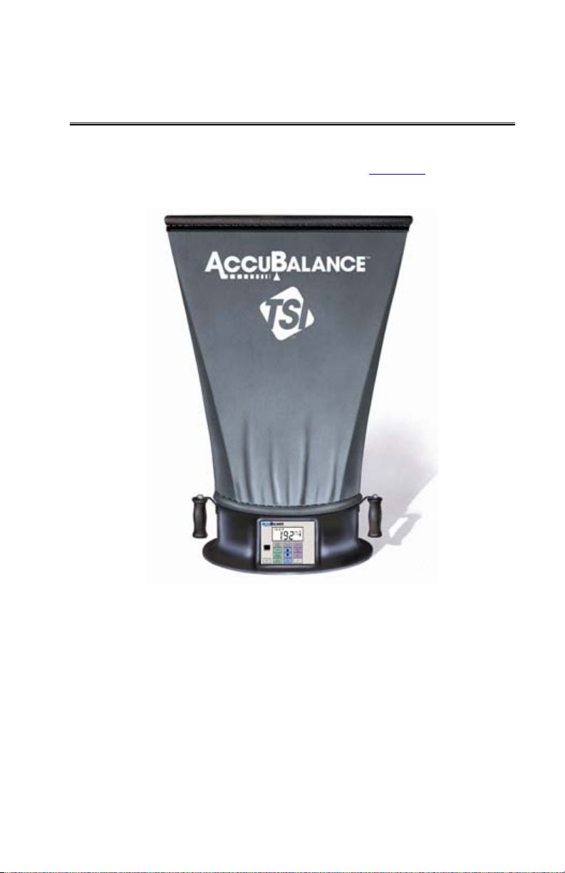
Figure 1: The A
Unpacking
Carefully unpack the instrument and accessories from the carrying case.
Check the individual parts against the list of components in Tables 1 through
3. If any are missing or damaged, notify TSI immediately.
CCUBALANCE® Air Capture Hood
1
Page 10
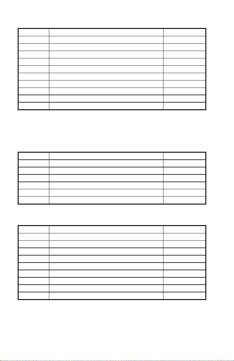
Table 1 List of components
Qty Item Part No.
1 Model 8371 base N/A
1 2 ft x 2 ft (610 mm x 610 mm) hood fabric 1307060
6 Frame support poles 1081390
4 2 ft (610 mm) frame tubing* 1081262
6 Right angle tubing connectors* 1081584
1 Battery holder 1081279
4 C-size batteries 1208018
1 Battery compartment cover 1081458
1 Carrying case 1319067
1 Operation and Service Manual 1980335
*Four 2 ft frame tubings and four of the right angle connectors are shipped
assembled inside the top of the hood fabric.
Table 2 List of components: -3 Hood Kit (adds 2 hoods to the
base kit)
Qty Item Part No.
1 2 ft x 4 ft (610 mm x 1220 mm) hood fabric 1801065
1 1 ft x 4 ft (305 mm x 1220 mm) hood fabric 1801066
6 2 ft (610 mm) frame tubing 1081262
4 1 ft (305 mm) frame tubing 1081260
6 Right angle tubing connectors 1081584
6 Straight tubing connectors 1302833
Table 3 List of components: -5 Hood Kit (adds 4 hoods to the
base kit)
Qty Item Part No.
1 2 ft x 4 ft (610 mm x 1220 mm) hood fabric 1801065
1 1 ft x 4 ft (305 mm x 1220 mm) hood fabric 1801066
1 1 ft x 5 ft (305 mm x 1525 mm) hood fabric 1801067
1 3 ft x 3 ft (915 mm x 915 mm) hood fabric 1801068
6 2 ft (610 mm) frame tubing 1081262
4 1 ft (305 mm) frame tubing 1081260
6 Right angle tubing connectors 1081584
6 Straight tubing connectors 1302833
2 1x tube connectors 1081580
Included with every manual is a registration card. Look for yours at the front
of this manual. Please complete and mail it promptly; it allows TSI to inform
you of product updates. You may also register on line by visiting the TSI
web site.
Chapter 1
2
Page 11
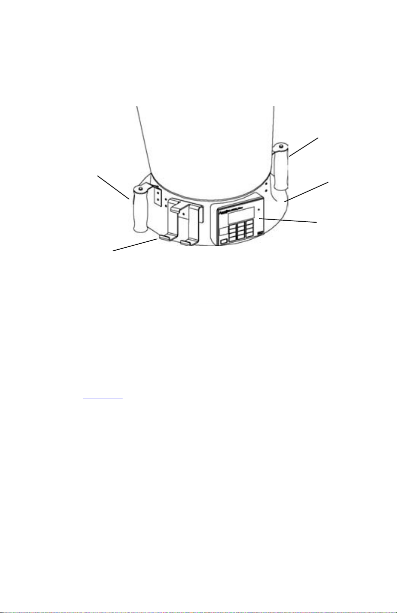
Parts Identification
Before proceeding with assembly and use of the A
CCUBALANCE
®
capture
hood, please familiarize yourself with the various parts of the instrument.
Refer to tables 1 through 3 for part descriptions and Figure 2 for general
location of major items.
1
6
2
3
4
5
Figure 2: A
CCUBALANCE
®
Components
1 Fabric hood - Basic hood assembly is covered later in this chapter,
other hoods are discussed in
Chapter 2.
2 Right handle with SAMPLE button - used for capturing information on
the display.
3 Meter base.
4 Electronic meter and display - Detailed keypad functions are covered
Chapter 2.
in
5 Printer bracket - Allows the portable printer to be attached to the
CCUBALANCE
A
®
base for ease of use and printing of data.
6 Left handle with PRINT button - Used to print that which is on the
display value to the portable printer.
Display
Each time the A
CCUBALANCE
®
capture hood is turned on, all segments
of the display will be shown momentarily. Below is a list of items that
will appear on the display and their use.
Set-Up
3
Page 12

5
9
3
2
Figure 3: Display of the Model 8371
1 Flow units: CFM (cubic feet per minute), l/s (liters per second),
3
/hr (cubic meters per hour), and m3/min (cubic meters per
m
minute). The A
CCUBALANCE
®
capture hood indicates flow
already corrected to "standard" conditions. Actual flow
conditions can be shown by pressing the ACTUAL/STANDARD
key (See
Chapter 2 for more detail operation)
2 Flow value: Large digits. See
specifications for range and
resolution.
3 Message area: Small digits.
4 Flow direction arrows: Indicates if supply or return air flow
calibration is being utilized by the A
CCUBALANCE
®
capture
hood.
Notice: Be sure this arrow points in the direction of flow through the
ACCUBALANCE® capture hood, otherwise the measurements made
will be inaccurate. To change the direction of the arrow, press the
RETURN/SUPPLY key.
5 “SAMPLE” will appear every time you press the SAMPLE button
or the button on the top of the right handle.
8
4
1
6, 7
6 “%
” will appear along with a value on the display during
power-up to indicate the percent of battery life remaining.
7 The
symbol will flash when the batteries have only about
10% life remaining. When the battery is too low to power the
instrument, “LO
” is displayed momentarily before the
instrument is automatically turned off.
Chapter 1
4
Page 13

8 “STD” or “ACTUAL” will be displayed at all times. “STD” refers
to readings that are based on standard conditions of 29.92 in.
Hg (760 mm Hg) and 70 °F (21.1 °C). “ACTUAL” refers to
readings that are converted to local conditions based on
temperature and barometric pressure. (See
Chapter 2 for more
details.)
”: K factor symbol to indicate that the readings have an
9 “K
f
adjustment factored in.
Display Units
CCUBALANCE
The A
®
capture hood is shipped with cubic feet per
minute (CFM) as the default flow unit (unless the metric version was
ordered). If you wish to change the units to l/s (liters per second),
3
/hr (cubic meters per hour), or m3/min (cubic meters per minute), see
m
Changing DIP Switch Settings in Chapter 2.
Keypad
Below is a drawing of the keypad, Figure 4, for the Model 8371. The
keys are referenced in the Basic Operation section of this chapter and
in Chapter 2 -
Operations in More Detail.
Set-Up
Figure 4: Keypad for the Model 8371
5
Page 14

Preparing the Instrument for Use
Installing the Batteries
CCUBALANCE
The A
operate. For your convenience, four alkaline batteries are included with
CCUBALANCE
the A
®
capture hood requires four C-size batteries to
®
capture hood.
To install the batteries, follow these three steps:
1 Remove the battery cover located behind the electronic meter on
the inner side of the A
CCUBALANCE
®
capture hood base. To
remove the battery cover, pull up on the latches located on the top
and bottom of the cover.
2 Place batteries in the battery holder located inside the battery
compartment. Follow the illustration on the battery holder for
correct battery orientation.
3 Replace the battery cover. Notice that the battery cover is designed
to fit only one way, with the tab pointing toward the fabric. Engage
the latches by pressing down on them.
Notice: Remove batteries from the battery compartment during shipping,
travel and transport. Jostling may jar the batteries loose and cause
damage to the ACCUBALANCE® capture hood.
If fresh, new alkaline batteries are used, the value will be near 100percent when first turned on. Other batteries, such as NiCd batteries,
may show a lower value even when they are fully charged.
Notice: The percent power remaining will not be accurate for NiCd
batteries because they do not discharge linearly with power use.
Hood Assembly
CCUBALANCE® capture hood is shipped from the factory partially
The A
assembled with the 2 ft
wish to use another hood size, see
x 2 ft nylon hood attached to the base. If you
Changing Hoods in Chapter 2.
To complete the assembly of the 2 ft
x 2 ft hood, follow these six steps:
1 Place the base of the A
CCUBALANCE® capture hood on the floor.
Chapter 1
6
Page 15

2 Lift the top of the fabric. Insert one end of a support pole into its
pole mount in the base of the A
CCUBALANCE
®
capture hood. There
is a cup in each corner of the frame to accept the other end of each
support pole. Helpful Hint: This step is made simpler by
temporarily resting the opposite corner of the fabric top on a table
edge.
3 Grasp the support pole. Bend the pole slightly to insert the top end
of the pole into the support pole cup located in the corner of the
fabric frame as shown in Figure 5.
Rod to pole cup
Figure 5: Installing a Support Pole
4 Insert the second support pole into the pole mount on the opposite
side of the A
CCUBALANCE
®
capture hood base.
5 Repeat step 3 for the second support pole.
6 Repeat steps 4 and 5 for the remaining two support poles.
Set-Up
7
Page 16

Basic Operation
CAUTION
HILE USING THE ACCUBALANCE® AIR BALANCING
W
INSTRUMENT TO TEST AIR FLOW IN DUCTS
COME INTO CONTACT WITH OR BE EXPOSED TO DUST
POLLEN
CONTAMINANTS
DUST
CONTAMINANTS
OR RESPIRATOR WHILE EMPLOYING THE
AIR BALANCING INSTRUMENT
, MOLD, FUNGUS, OR OTHER AIRBORNE
. IF YOU ARE OR MAY BE SENSITIVE TO
, POLLEN, MOLD, FUNGUS, OR OTHER AIRBORNE
, ALWAYS USE AN APPROPRIATE MASK
.
, YOU MAY
ACCUBALANCE
Start-Up
Press the ON/OFF button on the meter to turn on the power. The display
will initially indicate the percent of battery power remaining.
During start-up the A
CCUBALANCE
®
capture hood performs a self test
of its electronic functions. If an error is found, an error message will
appear on the display. Refer to Chapter 4,
message appears. If no errors are found, the A
Troubleshooting, if an error
CCUBALANCE
hood will proceed to the continuous measurement mode.
Selecting Flow Direction
CCUBALANCE
Each A
air separately for increased accuracy. The A
®
capture hood is calibrated for supply and return
CCUBALANCE
®
hood will assume that air is flowing in the same direction as the arrow
on the right-hand side of the display. Be sure this arrow points in the
direction of flow through the A
CCUBALANCE
®
capture hood, otherwise
measurements will be inaccurate. To change the direction of the arrow
press the RETURN/SUPPLY button.
Taking a Flow Measurement
You are now ready to start measuring flow rates. First, turn on the
CCUBALANCE
A
®
capture hood and select the appropriate flow
direction. For measuring supply air flow, the arrow must point down
away from the hood fabric; for return air flow measurements, the arrow
must point up toward the hood fabric.
Press the top of the A
CCUBALANCE
®
capture hood against the
perimeter edge of the diffuser or grille so as to form a seal.
CCUBALANCE® capture hood will begin to display values on a
The A
continuous basis. When you are ready to read a value press the
SAMPLE button or the button on the top of the right handle. The display
®
capture
capture
,
®
Chapter 1
8
Page 17

will show the word “SAMPLE” for the length of time as determined by
the TIME CONSTANT. When the sample is complete the unit will beep
and the value will remain on the display until SAMPLE is pressed again
and the meter will return to continuous measuring mode.
If the readings are fluctuating, adjust the TIME CONSTANT to a slower
value. Changing the TIME CONSTANT is detailed in the
Keypad
Function section of Chapter 2
When making a flow measurement, keep objects out of the flow path
at the base of the A
CCUBALANCE® capture hood (one foot clearance
minimum). However, it is acceptable to have a hand supporting the air
capture hood at the bottom of the base.
Notice: You must keep the A
CCUBALANCE
®
capture hood in place
during the entire sample interval and until the time-averaged
measurement appears on the display.
Turning the A
To turn off the A
CCUBALANCE
CCUBALANCE
®
Air Capture Hood Off
®
capture hood, simply press the
ON/OFF button.
Automatic Shut-off
CCUBALANCE
The A
®
capture hood will automatically shut itself off if
no switches or buttons have been pressed for 10 minutes. This feature
minimizes accidental loss of battery power. This feature may be
disabled by changing the factory settings. This is discussed in the
Switch Setting section of the next chapter.
DIP
Set-Up
9
Page 18

Page 19

Chapter 2
Operations in More Detail
This chapter presents more detail on the various features of the
CCUBALANCE
A
assemble different hood sizes. The A
acknowledge that a key has been pushed by producing a beep. This beep can
be disabled as explained in the
Keypad Functions
ON/OFF
Press to toggle between having the instrument on and off.
SUPPLY/RETURN
Press to toggle between measuring supply flow and return flow. The arrows
on the display will indicate the direction of the flow (S for return, T for
supply).
K FACTOR
Volume measurements with the A
take readings more quickly than methods used in the past. However, all
capture hood devices are affected by various types of diffusers, means of
connecting the diffuser to the duct work, and the type of duct work. The
CCUBALANCE
A
foot, 4 way throw diffuser. In some circumstances it is necessary to traverse
the ductwork to determine the “true” flow value. This true value is then
compared to the A
Factor or correction factor.
Press the K FACTOR button to toggle the K factor on or off. The “K
is shown on the display when the K factor is being used in the calculation.
Press and hold the K FACTOR button until the current K factor is displayed.
Release the button and use the S or T button to change the factor. Press
ENTER to accept it and return to measuring mode. The range of K factors
allowed will be 0.1 to 2.00. The default value is 1.00.
ACTUAL/STANDARD
Press the ACTUAL/STANDARD button to toggle between displaying actual and
standard flow rate. “STD” or “ACTUAL” will light up on the display (standard
is the default). Press and hold this button to view, enter, or change the
barometric pressure and ambient temperature. When the button is pressed
and held, the barometric pressure entered will be displayed. Release the
®
capture hood and explains how to change fabrics and
CCUBALANCE
®
capture hood will
DIP Switch Settings section of this chapter.
CCUBALANCE
®
capture hood is calibrated by attaching it to a 2 foot x 2
CCUBALANCE
®
capture hood. This comparison is a K
®
capture hood is a means to
” symbol
f
11
Page 20

button, use the ST buttons to change the value and ENTER to accept it. The
ambient temperature will then be displayed. Press the S or T button to
change the value and ENTER to accept it and return to measuring mode.
Ambient temperature and barometric pressure can also be set by pressing
either ST when the parameter is displayed during power-up.
TIME CONSTANT
Press to display the current time constant. Press ST to scroll through the
time constant choices, which are 1 s, 3 s, 5 s, 10 s, 15 s, 20 s. Press ENTER to
accept choice and return to measuring mode. The default value is 1 s.
PRINT or LEFT HANDLE BUTTON
Press to print the reading on the display to the portable printer.
ST
Press to scroll through choices. Press either S or T to set barometric
pressure and temperature when they are displayed during power-up. Used in
field calibration mode for flow.
SAMPLE or RIGHT HANDLE BUTTON
Press to take a sample averaged over the length of the time constant.
“SAMPLE” will flash on the display while the reading is being taken, and
then the value and “SAMPLE” will be held on the display until SAMPLE is
pressed again, at which time the instrument will return to measuring mode.
This also prints the result to the portable printer if connected.
LIGHT
Press to toggle between having the back-lit display turn on and off. When
the instrument is turned off, the backlight turns off and does not
automatically turn on the next time the instrument is turned on.
Field Calibration
Turn DIP switch 7 to the on position, see
the chapter. To adjust the flow value, press both the
DIP Switch Settings section later in
S and T buttons
simultaneously. When “CAL” is displayed, release the buttons. Press either
S or T buttons to change to a desired percentage adjustment and press
the
ENTER to accept it. The percentage adjustment ranges from 0% to plus or
minus 12.5%. To use the instrument with the adjusted values, DIP switch 7
must remain in the ON position. All adjustment values and offsets are stored
in the instrument and will remain the same until changed again. To return to
all factory settings, turn DIP switch 7 off.
Changing Hoods
CCUBALANCE
The A
®
capture hood is shipped with a 2 ft x 2 ft hood attached
to the base. Four other hood sizes are available from TSI and can be
Chapter 2
12
Page 21

purchased separately. Available hood sizes are identified by the dimensions
of the frame structure at the top of the hood and include 2 ft
x 5 ft and 3 ft x 3 ft .
1 ft
x 4 ft, 1 ft x 4 ft,
To change hood sizes, first remove the hood currently attached to the base.
To remove the attached hood, first unlatch the cinch belt where the fabric is
attached to the base. Then remove the fabric from its frame structure by
peeling back the Velcro® from the aluminum frame tubing. Notice that the
fabric stretches around the outside, then up and over the frame structure. The
Velcro on the fabric reaches down to mate with the Velcro on the frame
structure. Notice also that all Velcro surfaces on the frame tubing face
inward. Finally, fold up the fabric you just removed so that it can fit into one
of the accessory pockets inside the A
CCUBALANCE
®
carrying case. It is a
good idea to fold the fabric so that the tag identifying its size remains visible
for future reference.
x 4 ft Hood
2 ft
To assemble and attach the 2 ft
x 4 ft hood, carefully follow these 10 steps:
1 Build the 2 ft
x 4 ft frame structure as shown in Figure 6 using six 2 ft
aluminum frame tubing pieces, four right-angle tubing connectors, and
two straight tubing connectors. Remember to construct the frame so
that all Velcro surfaces face in (toward the center of the structure).
Notice: Make sure that all support pole cups in the aluminum frame tubing
pieces are facing downward.
Figure 6: Diagram of 2 ft x 4 ft frame
2 Unfold the 2 ft
x 4 ft hood fabric.
Operations in More Details
13
Page 22

3 Insert the frame into the fabric and fasten the fabric to the frame using
the Velcro surfaces. The fabric stretches around the outside, then up
and over the frame structure. The Velcro
to mate with the Velcro
®
on the inner surface of the frame structure.
®
on the fabric reaches down
When completed, the soft rubber gasket material should lie in a straight
line along the top surface of all four sides of the frame.
Notice: Be sure to press the Velcro surfaces firmly together. When
completed, the hood fabric will be stretched fairly taut and will
require good bonding of the fabric to the frame.
4 Stretch the cinch belt at the bottom of the fabric over the lip around the
top of the molded plastic base of the A
CCUBALANCE
Align the seams of the fabric panels with the pairs of screw heads that
hold the four pole mounts to the A
CCUBALANCE
®
capture hood.
®
base. Align so that
the cinch belt latch is on the side of the base opposite the electronics
meter.
5 Pull the strap at the latch very tight to attach the fabric to the base.
Make sure that the strap stays tucked under the protruding lip all
around the top of the base. Pay particular attention to where the strap
passes the handles.
6 Now it is time to install the support poles. You will find four white
marks on the inside top edge of the fabric. These marks identify the
location of cups on the underside of the frame tubing that will accept
the ends of the support poles.
At this time it is helpful to be near a table or some other thigh-high
surface to help hold up the fabric while you install the first support
pole.
7 With the base of the A
CCUBALANCE
®
capture hood on the floor, lift the
fabric frame up so that a white mark is directly in front of you. Support
the opposite side of the frame structure on a nearby table or other level
surface.
Take one support pole and insert one end into its pole mount in the
CCUBALANCE
A
®
base.
Bend the pole slightly to guide the other end into the corresponding
support pole cup located on the underside of the frame near the white
mark on the fabric.
8 Repeat step 7 until all four support poles are installed.
Chapter 2
14
Page 23

9 Now that the hood is assembled and the fabric is stretched tight, it is a
good practice to check the rubber gasket around the top edge of the
CCUBALANCE
A
®
capture hood fabric. In order to achieve a good
straight alignment of the rubber gasket along the top of the frame
structure, you may need to peel back and re-attach small portions of the
Velcro surfaces.
10 Finally, at the corners, tuck the straight rubber gasket flaps under the
edges cut at an angle. This will create a virtually leak-free, soft, pliant
seal.
x 4 ft Hood
1 ft
To assemble and attach the 1 ft
x 4 ft hood, carefully follow these 10 steps:
1 Build the 1 ft
x 4 ft frame structure as shown in Figure 7 using four 2 ft
aluminum frame tubing pieces, two 1 ft aluminum frame tubing pieces,
four right-angle tubing connectors, and two straight tubing connectors.
Remember to construct the frame so that all Velcro surfaces face in
(toward the center of the structure).
Notice: Make sure that all support pole cups in the aluminum frame tubing
pieces are facing downward.
Figure 7: Diagram of 1 ft x 4 ft frame
2 Unfold the 1 ft
x 4 ft fabric hood.
Continue with steps 3 through 10, beginning on page
Operations in More Details
14.
15
Page 24

x 5 ft Hood
1 ft
To assemble and attach the 1 ft
x 5 ft hood, carefully follow these 10 steps:
1 Build the 1 ft
x 5 ft frame structure as shown in Figure 8 using four 2 ft
aluminum frame tubing pieces, two 1x tube connectors, two 1 ft
aluminum frame tubing pieces, and four right-angle tubing connectors.
Remember to construct the frame so that all Velcro surfaces face in
(toward the center of the structure).
Notice: Make sure that all support pole cups in the aluminum frame tubing
pieces are facing downward.
Figure 8: Diagram of 1 ft x 5 ft frame
2 Unfold the 1 ft
x 5 ft fabric hood.
Continue with steps 3 through 10, beginning on page
14.
x 3 ft Hood
3 ft
To assemble and attach the 3 ft
x 3 ft hood, carefully follow these 10 steps:
1 Build the 3 ft
x 3 ft frame structure as shown in Figure 9 using four 2 ft
aluminum frame tubing pieces, four 1 ft aluminum frame tubing pieces,
four right-angle tubing connectors, and four straight tubing connectors.
Remember to construct the frame so that all Velcro surfaces face in
(toward the center of the structure).
Notice: Make sure that all support pole cups in the aluminum frame tubing
pieces are facing downward.
Chapter 2
16
Page 25

Figure 9: Diagram of 3 ft x 3 ft frame
2 Unfold the 3 ft
x 3 ft fabric hood.
Continue with steps 3 through 10, beginning on page
14.
Changing DIP Switch Settings
You can change flow units and time constants by adjusting the settings of
the DIP switches located inside the battery compartment. To gain access to
the DIP switches, first turn off the A
CCUBALANCE
®
capture hood and lay
down the instrument with the electronic meter facing down.
Remove the battery compartment cover by pulling up on the two latches.
You will see the switches numbered 1 through 8 in the corner of the battery
compartment. You may wish to remove or tilt up the battery pack to allow
easier access to the switches. The DIP switches are shown in Figure 10.
Figure 10: Location of DIP Switches
Operations in More Details
17
Page 26

You may change the switch settings using the tip of a ball-point pen, pencil,
compass, small screwdriver, or other small, pointed object. Refer to Table 4
for switch settings.
Table 4: DIP Switch Settings
Switch Number Setting: Function
1,2 1 OFF, 2 OFF: Flow units = CFM
1 OFF, 2 ON: Flow units = m3/hr
1 ON, 2 OFF: Flow units = l/s
1 ON, 2 ON: Flow units = m3/min
3 OFF: Pressure units = in. Hg
ON: Pressure units = mm Hg
4
OFF: Temperature units = °F
ON: Temperature units = °C
5 OFF: Auto shut off = on
ON: Auto shut off = off
6 OFF: Decimal for fractions
ON: Comma for fractions
7 OFF: Field calibration disabled
ON: Field calibration enabled
8 OFF: Audible buzzer on
ON: Audible buzzer off
Connecting the Optional Printer
To connect the optional printer to the A
CCUBALANCE
®
capture hood, locate
the Printer Interface Cable (supplied with the optional printer) and connect
the 9-pin end labeled “PRINTER” to the printer and the other end to the data
port of the A
base of the A
CCUBALANCE
CCUBALANCE
®
capture hood. The printer can be attached to the
®
capture hood by clipping it into the printer
bracket located to the left of the display. The printer can also be easily used
by clipping it to the belt of the user. The printer must be set to the same baud
rate as the A
CCUBALANCE
®
capture hood. Always turn the ACCUBALANCE®
capture hood on before the printer. If the printer prints question marks
(??????), asterisks (******), or random characters, reset it by turning it off
and then on again. If necessary, refer to the Portable Printer Operation and
Service Manual.
Caution: This symbol is used to indicate that the data
port of the A
CCUBALANCE
®
capture hood is not
intended for connection to a public
telecommunications network. Connect the data port
only to another RS232 port.
Chapter 2
18
Page 27

Chapter 3
Maintenance
CCUBALANCE
The A
CCUBALANCE® capture hood is used with reasonable care, it should be able
A
to make precise measurements over a long time period. Some of the
components can be cleaned periodically. When cleaning the components,
please follow the instructions given below.
Fabric Hood
The hoods can be washed with mild detergent and cold water. When
washing the hood, keep the hood away from objects with sharp corners or
sharp edges. Careless cleaning may cause damage.
If the fabric gets ripped it should be replaced or repaired. Duct tape can be
placed over the rip on both sides of the fabric for temporary repair.
To replace a damaged fabric or to order a different fabric size, contact TSI
for replacement fabric information.
If you wish to order a new hood fabric, use the following part numbers
shown in Table 5.
Table 5: Hood Fabric Part Numbers Fabric Hood Size Part Number
2 ft x 2 ft (610 mm x 610 mm) 800590
2 ft x 4 ft (610 mm x 1220 mm) 800591
1 ft x 4 ft (305 mm x 1220 mm) 800592
3 ft x 3 ft (915 mm x 915 mm) 800593
1 ft x 5 ft (305 mm x 1525 mm) 800594
Frame Kit 1081263
It is recommended that you purchase a frame kit whenever you purchase a
hood other than the 2 ft
tubing and connectors required to build frames for the various size hoods.
The frame kit consists of the following parts:
4 pieces 1-foot frame tubing
2 pieces 2-foot frame tubing
6 pieces straight tubing connectors
®
capture hood is designed for long-term field use. If the
x 2 ft size. The frame kit contains all extra frame
19
Page 28

Meter
CCUBALANCE
The A
not try to detach the meter from the base. The A
®
capture hood has a built-in electronic flow meter. Do
CCUBALANCE
®
capture hood
should be used and stored within the specified temperature range, 32 –
140°F (0-60°C). The meter case, display screen and membrane switch can be
cleaned using a damp cloth with mild detergent solution. Do not immerse the
meter in water. Wipe the meter dry before use.
Manifold
If you observe the flow sensing taps of the manifold becoming clogged with
dust or other material, clean them with a damp cloth. The manifold should
be kept in place during cleaning. Do not apply excessive forces on the grid
of the manifold. If any part of the grid becomes damaged, please contact TSI
for repair information.
Cases
If the instrument case or storage case needs cleaning, wipe it off with a soft
cloth and isopropyl alcohol or a mild detergent. Never immerse the
CCUBALANCE
A
®
capture hood. If the meter face of the ACCUBALANCE
®
capture hood becomes broken, it must be replaced immediately to prevent
access to hazardous voltage.
Calibration
TSI recommends an annual calibration for the A
CCUBALANCE
®
capture
hood. For a nominal fee, TSI will calibrate the unit and return it to you with
a certificate of calibration and NIST traceability. This 'annual checkup'
assures you of consistently accurate readings. To calibrate the
CCUBALANCE
A
includes the meter, the base, the manifold and any fabrics used. Everything
should be packed carefully within the A
®
capture hood, please ship TSI the complete package that
CCUBALANCE
®
carrying case and
then inside a proper shipping box, such as the original shipping box.
Ship directly to: TSI, Inc.
ATTN: Customer Service
500 Cardigan Road
Shoreview, MN 55126-3996
20 Chapter 3
Page 29

Chapter 4
Troubleshooting
Table 6 lists the symptoms, possible causes, and recommended solutions for
common problems encountered with the A
CCUBALANCE
your symptom is not listed, or if none of the solutions solves your problem,
please contact TSI.
Table 6. Troubleshooting the A
CCUBALANCE® Air Capture Hood
Symptom Possible Causes Corrective Action
No display Unit not switched on
Low or dead batteries
Dirty battery contacts
Battery holder not
connected
" "flashing on
the display
Low battery charge
Dirty battery contacts
"0" (Flow is under
range)
Trying to read too low a
flow
Object is blocking flow
through A
CCUBALANCE
Sensor grid tubes are
plugged
CCUBALANCE is not
A
sealing around diffuser
“OVER” (Flow is
over range)
Trying to read too high
a flow
®
capture hood. If
Press ON/OFF button
Replace the batteries
Clean the battery
contacts
Plug in battery holder
Replace the batteries.
Clean the battery
contacts
Flow may not be
measurable using the
CCUBALANCE
A
Remove obstruction
Clean the tubes
Reposition the
CCUBALANCE to form
A
a seal
Flow may not be
measurable using the
CCUBALANCE
A
21
Page 30

Symptom Possible Causes Corrective Action
Flow reading
fluctuates badly
"ERR1" appears
"ERR2" appears
"ERR3" appears
The flow is fluctuating Use a longer time
constant
Unit is or was recently
in ambient temperature
outside of operating
temperature
Temperature
compensation sensor is
damaged
The flow sensor is
giving an erroneous
reading
The A
CCUBALANCE has
detected a calibration
fault
Allow unit to stabilize
in the operating
temperature range of 32
- 140ºF (0 - 60ºC)
Return to the factory
for service
Return to the factory
for service
Return to the factory
for service
22 Chapter 4
Page 31

Appendix A
Back Pressure
It is commonly known that an air capture hood may induce a back pressure.
In general, back pressures are caused by restrictions in the flow path as well
as frictional pressure losses. In order to improve accuracy and sensitivity, all
air capture hoods incorporate a contracted flow section. The contracted
section restricts the flow through the hood which induces a back pressure. A
hood having a more abrupt contraction than the A
CCUBALANCE
hood may induce greater back pressure due to the turbulence caused by the
abrupt contraction. In addition any apparatus within the hood, such as
supporting poles and the flow manifold, also induces some frictional
pressure drop.
Back pressure may cause slight errors in the flow measurements. Figure 11
shows the pressure drop through the A
CCUBALANCE
®
capture hood over its
entire flow range. As shown in the Figure, the back pressure is only 0.05 in.
O at a flow rate as high as 1000 CFM.
H
2
®
capture
Figure 11: Pressure Drop through the
CCUBALANCE
A
®
Air Capture Hood
23
Page 32

If you wish to make back pressure corrections, you must first determine the
back pressure correction factor, C
. The back pressure correction factor, Cb,
b
can be determined as follows:
V
o
Cb = ---- (1)
V
where V and Vo are the average air velocities in the duct ahead of the
diffuser with and without the capture hood in place, respectively. With the
known correction factor, the back-pressure corrected flow can be determined
using Equation (2):
x C
Back-pressure corrected flow = Displayed flow
(2)
b
24 Appendix A
Page 33

Appendix B
Specifications
Flow Range 30 to 2,000 CFM
(15.0 to 1,000 l/s,
50 to 3,500 m
0.84 to 55.0 m
Accuracy ±5% reading ±5 CFM
(±5% reading ±2.4 l/s,
±5% reading ±8.5 m
±5% reading ±0.15 m
Operating Temperature Range 32-140°F (0-60°C)
Instrument Operating Conditions Altitude up to 13,000 ft
(4000 meters)
Relative humidity up to 80%
RH, non-condensing
Pollution degree 1 in
accordance with IEC 664
Weight (using 2 ft × 2 ft in Hood) 7 lb 6 oz (3.4 kg)
Power 4 C-size batteries
(4 alkaline batteries provided)
Battery Life At least 40 hrs of continuous use
Carrying Case 26 in × 26 in × 7 in
(660 mm × 660 mm × 180 mm)
Hood Sizes Available
Standard: 2 ft × 2 ft; (610 mm × 610 mm)
Optional: 2 ft × 4 ft; (610 mm × 1220 mm)
1 ft × 4 ft; (305 mm × 1220 mm)
1 ft × 5 ft; (305 mm × 1525 mm)
3 ft × 3 ft; (915 mm × 915 mm)
RS-232C Output ASCII Character codes
1200 Baud
No parity
8 data bits
1 stop bit
No handshaking
Specifications are subject to change without notice.
3
/hr,
3
/min)
3
/hr,
3
/min)
25
Page 34

TSI Incorporated – 500 Cardigan Road, Shoreview, MN 55126 U.S.A
USA Tel: +1 800 874 2811 E-mail: info@tsi.com
UK Tel: +44 149 4 459200 E-mail: tsiuk@tsi.com
France Tel: +33 491 11 87 64 E-mail: tsifrance@tsi.com
Germany Tel: +49 241 523030 E-mail: tsigmbh@tsi.com
India Tel: +91 80 41132470 E-mail: tsi-india@tsi.com
China Tel: +86 10 8260 1595 E-mail: tsibeijing@tsi.com
Website: www.tsi.com
Website: www.tsiinc.co.uk
Website: www.tsiinc.fr
Website: www.tsiinc.de
Contact your local TSI Distributor or visit our website www.tsi.com for more detailed specifications.
P/N 1980335 Rev D Copyright © 2009 by TSI Incorporated Printed in U.S.A.
 Loading...