

Page 1

ENERGY AND COMFORT
Combustion Analysis
CA-CALC™
Combustion Analyzers
Series CA-6100
Operation and Service Manual
P/N 1980451 Revision G
August 2010
Page 2

Page 3

3
Copyright ©
TSI Incorporated / 2002–20010 / All rights reserved.
Part Number
1980451 / Revision G
Address
TSI Incorporated / 500 Cardigan Road / Shoreview, M N 55126 / USA
Fax No.
(651) 490-3824
LIMITATION OF WARRANTY AND LIABILITY (effective July 2000)
Seller warrants the goods sold hereunder, under normal use and service as described in the
operator's manual, shall be free from defects in workmanship and material for twenty-four (24)
months, or the length of time specified in the operator's manual, from the date of shipment to the
customer. This warranty period is inclusive of any statutory warranty. This limited warranty is
subject to the following exclusions:
a. Batteries are warranted for 90 days from the date of shipment to the customer.
Electrochemical gas sensors are warranted for a period of twelve (12) months from the date
of shipment to the customer.
b. Parts repaired or replaced as a result of repair services are warranted to be free from defects
in workmanship and material, under normal use, for 90 days from the date of shipment.
c. Seller does not provide any warranty on finished goods manufactured by others or on any
fuses, batteries or other consumable materials. Only the original manufacturer's warranty
applies.
d. Unless specifically authorized in a separate writing by Seller, Seller makes no warranty with
respect to, and shall have no liability in connection with, goods which are incorporated into
other products or equipment, or which are modified by any person other than Seller.
The foregoing is IN LIEU OF all other warranties and is subject to the LIMITATIONS stated
herein. NO OTHER EXPRESS OR IMPLIED WARRANTY OF FITNESS FOR
PARTICULAR PURPOSE OR MERCHANTABILITY IS MADE.
TO THE EXTENT PERMITTED BY LAW, THE EXCLUSIVE REMEDY OF THE USER OR
BUYER, AND THE LIMIT OF SELLER'S LIABILITY FOR ANY AND ALL LOSSES,
INJURIES, OR DAMAGES CONCERNING THE GOODS (INCLUDING CLAIMS BASED
ON CONTRACT, NEGLIGENCE, TORT, STRICT LIABILITY OR OTHERWISE) SHALL
BE THE RETURN OF GOODS TO SELLER AND THE REFUND OF THE PURCHASE
PRICE, OR, AT THE OPTION OF SELLER, THE REPAIR OR REPLACEMENT OF THE
GOODS. IN NO EVENT SHALL SELLER BE LIABLE FOR ANY SPECIAL,
CONSEQUENTIAL OR INCIDENTAL DAMAGES. SELLER SHALL NOT BE
RESPONSIBLE FOR INSTALLATION, DISMANTLING OR REINSTALLATION COSTS
OR CHARGES. No Action, regardless of form, may be brought against Seller more than 12
months after a cause of action has accrued. The goods returned under warranty to Seller's
factory shall be at Buyer's risk of loss, and will be returned, if at all, at Seller's risk of loss.
Buyer and all users are deemed to have accepted this LIMITATION OF WARRANTY AND
LIABILITY, which contains the complete and exclusive limited warranty of Seller. This
LIMITATION OF WARRANTY AND LIABILITY may not be amended, modified or its terms
waived, except by writing signed by an Officer of Seller.
Service Policy
Knowing that inoperative or defective instruments are as detrimental to TSI as they are to our
customers, our service policy is designed to give prompt attention to any problems. If any
malfunction is discovered, please contact your nearest sales office or representative, or call TSI's
Customer Service department at (651) 490-2811 or (800) 874-2811.
Page 4

4
(This page intentionally left blank)
Page 5

i
Contents
Introduction ........................................................................................ 1
Manual Purpose ............................................................................ 1
Using This Manual ......................................................................... 1
Warnings and Cautions ................................................................. 1
Chapter 1 Instrument Description ................................................... 3
Chapter 2 Unpacking ........................................................................ 5
List of Standard Components ........................................................ 5
Accessories and Replacement Parts ............................................ 5
Chapter 3 Component Identification ............................................... 7
The Gas Sensors .......................................................................... 9
The Sampling Probe ...................................................................... 9
Flue Probe Thermocouple (CA-6120, CA-6130, CA-6140) .......... 9
On-Board Temperature Measurement (CA-6120, CA-6130,
CA-6140) .................................................................................... 9
Diaphragm Pump .......................................................................... 9
Draft Sensor (CA-6110, CA-6140) .............................................. 10
Water Trap ................................................................................... 10
Optional Combustion Supply Air Thermocouple Probe
(CA-6120, CA-6130, CA-6140) ................................................ 10
Optional Protective Boot .............................................................. 10
Schematic Representation of Series CA-6100 CA-CALC
Analyzer ................................................................................... 11
Chapter 4 Getting Started .............................................................. 13
Supplying Power ......................................................................... 13
Connecting the Sampling Probe ................................................. 13
Connecting the Optional Combustion Supply Air
Temperature Probe (CA-6120, CA-6130, CA-6140) ............... 14
Connecting the Optional Portable Printer .................................... 14
Connecting to a Computer .......................................................... 15
Default Instrument Settings ......................................................... 15
Factory Defaults and Language Selection .................................. 15
Chapter 5 Basic Operation ............................................................. 17
Buttons and Button Operations ................................................... 17
Startup ......................................................................................... 18
Characters and Display Icons ..................................................... 19
Measurements and Calculations ................................................. 20
Page 6

ii
Chart of Measurements for Series CA-6100 CA-CALC
Instrument Models .................................................................... 20
Data Display, Viewing Measurements and Calculations ............. 22
Using the Sampling Probe ........................................................... 23
Draft Measurement (CA-6110, CA-6140) .................................... 24
Printing to the Portable Printer and to a Computer
(All Models)............................................................................... 25
Handling Data .............................................................................. 27
Chapter 6 MENU Options ............................................................... 31
LITE Menu Option........................................................................ 32
FUEL Menu Option ...................................................................... 32
UNIT Menu Option (Changing Units) .......................................... 33
INT.S MENU Option .................................................................... 34
TIME MENU Option (Set Time and Date) ................................... 34
CAL MENU Option ...................................................................... 34
CAL.F MENU Option—Setting the Calibration Factor ................. 39
BAUD Rate MENU option ............................................................ 40
COMM MENU Option—Set the Output Communications
Device ....................................................................................... 41
FP MENU Option—Fuel Parameters (CA-6120, CA-6130,
CA-6140) .................................................................................. 42
Fuel Parameter Descriptions for U.S. Fuels ................................ 43
FP Fuel Parameters for Siegert Calculation—Siegert Fuel
Parameters ............................................................................... 43
LANG MENU Option .................................................................... 44
Chapter 7 Setup for Gas Calibration ............................................. 45
The Calibration Setups ................................................................ 45
Chapter 8 Maintenance and Troubleshooting .............................. 49
Emptying Water Trap ................................................................... 49
Changing the (optional) Water Trap Filter ................................... 49
Cleaning the Sample Probe ......................................................... 50
Installing a Gas Sensor ............................................................... 50
Adding a CO Sensor to the Model CA-6120 ............................... 52
Disabling CO Sensor Recognition by a Model CA-6130 ............. 52
Appendix A Error Codes ................................................................ 53
Appendix B Calculations ................................................................ 55
COu Undiluted CO Concentration Calculation ............................ 55
Excess Air Calculation ................................................................. 55
Calculating Combustion Efficiency for U.S. Fuels ....................... 55
Siegert Formula ........................................................................... 56
Determining CO2 Using the O2 Concentration ............................ 57
Page 7

iii
A General Equation for the Combustion of a Simple
Hydrocarbon in Air ................................................................... 57
Calculating CO2 Max From the Carbon Content ......................... 57
Calculation of Combustion Air Requirement ............................... 57
Appendix C Series CA-6100 CA-CALCTM Combustion
Analyzer Specifications ............................................................ 59
Page 8

iv
(This page intentionally left blank)
Page 9

1
!
!
Introduction
Manual Purpose
This manual describes the operation and maintenance of TSI Series
CA-6100 CA-C
6130, and 6140).
Using This Manual
ALC™ portable combustion analyzers (Models 6110, 6120,
Before using your CA-C
its entirety.
Much of the information in this manual is applicable for all Series CA-6100
instruments. Where information is applicable to a particular model, notation
is made.
Warnings and Cautions
The manual assumes that you have a basic understanding of combustion
safety concerns and are thoroughly familiar with the fuel burning equipment
being tested. If you are using measurements as the basis for equipment
adjustments, rely on your good judgment and experience together with the
measured data. This is especially important where safety issues are of
concern. Equipment adjustments must always coincide with the fuel burning
equipment manufacturer’s recommendations.
ALC™ Combustion Analyzer, review this manual in
WARNING
High temperatures and toxic gases are produced when
fossil fuels are burned. Only qualified individuals,
thoroughly familiar with operating and adjusting fuelburning equipment, should use gas measurements for
the purpose of making equipment adjustments.
Note
The CA-CALC™ analyzer is not intended for use as a
continuous monitor.
Page 10

2
Notes: Best results are obtained if the CA-CALC™ combustion analyzer is
allowed to stabilize at the temperature of the test environment before
using.
To reduce sensor exposure to gas and to reduce build up of water
vapor in the sampling lines and water trap, turn the pump off when
not making measurements.
Page 11
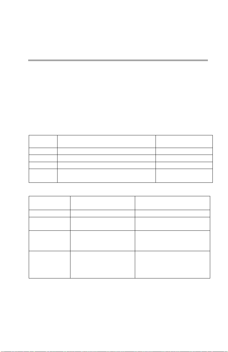
Model
Description
Measurements
CA-6110
Safety Monitor, CO and Draft,
CO, Draft
CA-6120
Boiler and Furnace Efficiency Monitor
O
2,
Temperature
CA-6130
Boiler and Furnace Tune-up Monitor
CO, O
2,
Temperature.
with Draft
Draft
CA-6110
CO and Draft
n/a
2
CA-6130
O2, CO, Flue/stack and
Excess air, Fuel Efficiency,
CO, CO ratio
CA-6140
O2, CO, Flue and Supply
Excess air, Fuel Efficiency,
Chapter 1
Instrument Description
The Series CA-6100 CA-CALC™ Combustion Analyzers are portable
instruments designed for measuring combustion gases, combustion gas
temperatures and draft pressure. These measurements are used to evaluate
the performance of burners in boilers, furnaces, and hot water tanks. From
the measured data, the CA-C
of combustion parameters including CO concentration, excess air, CO
combustion efficiency and draft. Measurements for your CA-C
analyzer will depend upon its Model number designation.
Series CA-6100 CA-C
ALC™ combustion analyzers calculate a variety
ALC™
TM
ALC
Combustion Analyzer Models
level,
2
CA-6140 Boiler and Furnace Tune-up Monitor
Series CA-6100 CA-C
Model
Number
CA-6120 O2, Flue/stack and
The Series CA-6100 CA-C
probe having an in-line water trap and particulate filter. For instruments
measuring temperature, the sample probe has an integral thermocouple.
The Series CA-6100 CA-C
power supply or AA-size batteries.
CO, O
ALC™ Measurements and Calculations
Measured with
Sensor
Calculations
Excess air, Fuel Efficiency,
Supply Air Temperature
Supply Air Temperature
Air Temperature, Draft
Loss, qA, %CO
Loss, qA, %CO2, undiluted
Loss, qA, %CO2, undiluted
CO, CO ratio, draft and
differential pressure.
ALC™ Analyzers are supplied with a sampling
ALC™ Analyzers operate using either an AC
Temperature,
2,
3
Page 12

4
The Series CA-6100 CA-CALC™ Analyzers can store individual data
samples (up to 24), and print the data to a portable printer or computer.
Stored data can be saved over a user-defined interval and averaged if
required.
The Series CA-6100 CA-C
ALC™ Analyzers (not CA-6110) have a variety of
standard fuels, and enable you to modify the fuel parameters, or to install
your own user defined fuel. Loss and efficiency are calculated from standard
heat-loss calculations or using the Siegert formula (refer to Appendix B
).
Chapter 1
Page 13

1
Sample probe with water trap, draft line and
801991
Sample probe with water trap and draft line
801992
4
AA cell alkaline batteries
1 Operation and Service manual
1980451
1
Combustion Supply Air thermocouple Type K
3013003
1
Portable printer kit
801994
1
Universal Power supply 7.2 V with assorted plug
2182003
1
Boot with magnet and carrying strap
801995
1
Computer cable
8940
1
Hard side Carrying case
1500134
1
Replacement pump
801996
1
CO replacement sensor
802006
1
O2 replacement sensor
802012
1
Water trap filters
1602309
1
Lithium battery
1208028
1
Calibration kit O2 (N2 gas) and CO
802003
Chapter 2
Unpacking
Carefully unpack your CA-CALC™ combustion analyzer and accessories
from the carrying case. Check the individual parts against the list of
components in the table below. If items are missing or damaged, notify TSI
immediately.
List of Standard Components
Qty. Item Component Part/ Model
1 Series CA-6100 CA-CALC combustion analyzer,
carrying case, and boot (case and boot not
included with Model CA-6110)
temperature
Sample probe with water trap and temperature
Accessories and Replacement Parts
Item Part/Model
types
801990
5
Page 14

6
(This page intentionally left blank)
Chapter 2
Page 15
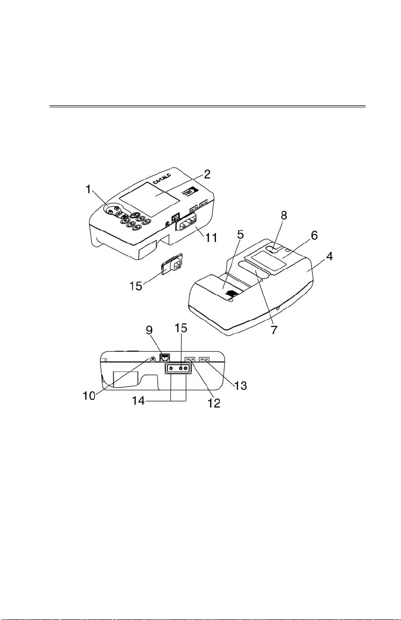
Chapter 3
Component Identification
Key components of the CA-CALC™ combustion analyzer and sampling
probe are identified in Figures 1 and 2, and under section headings in the
text that follows.
1. Buttons 9. RS-232 interface connector
2. Display 10. AC power input connector
3. Top cover 11. Sample port*
4. Case bottom 12. Flue/stack thermocouple port*
5. Battery cover 13. Port for supply Air temperature probe*
6. Sensor cover 14. Optional draft measurement ports [left
side (reference), right side (stack)]*
7. Damping chamber 15. Sample port Models CA-6120, CA-6130*
8. Gas vent
Figure 1. Series CA-6100 CA-CALC™ Combustion Analyzer
*For 11–15 see Figure 4 for Model details.
7
Page 16
8
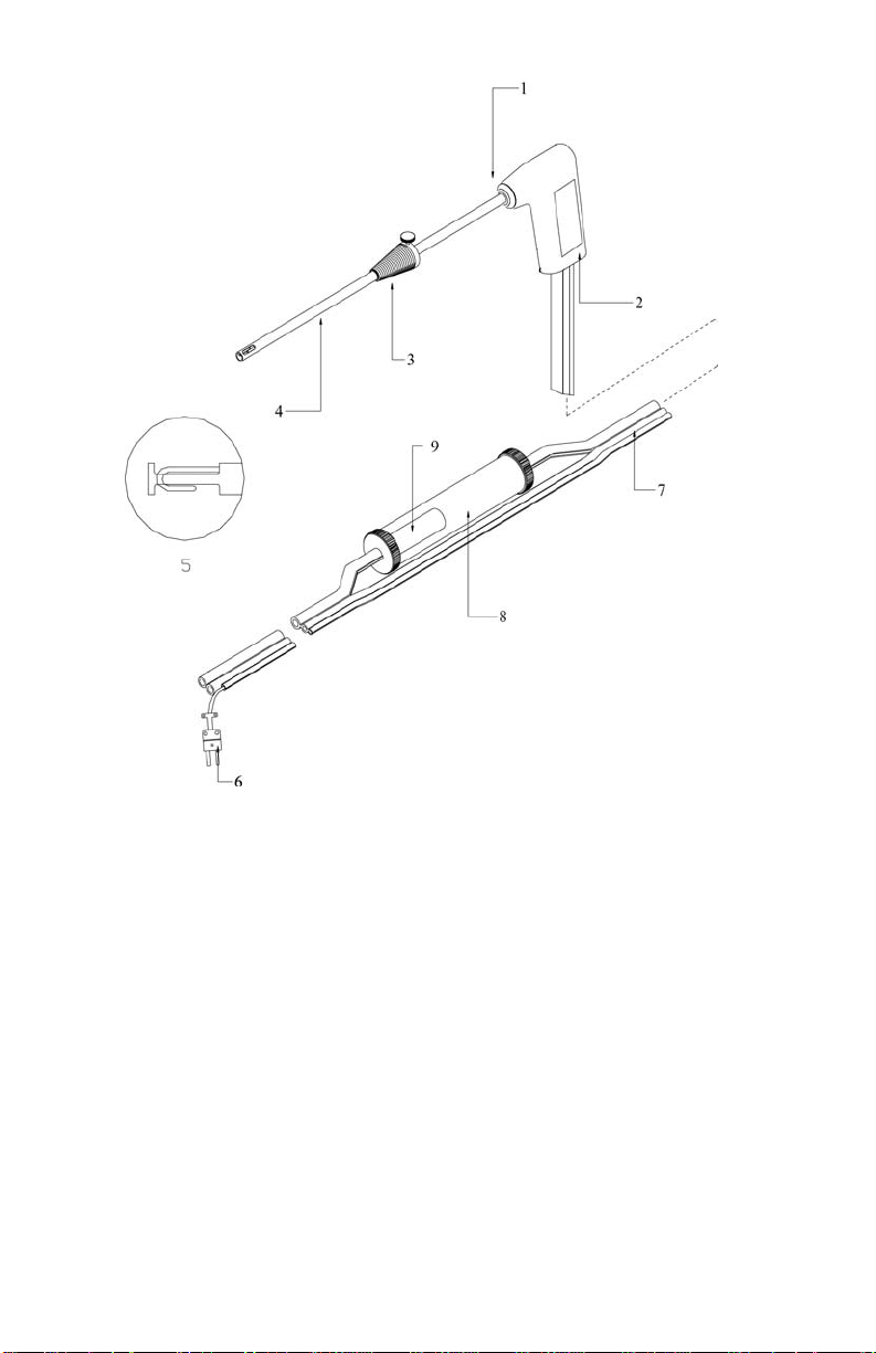
1. Tube retaining fitting
(some models)
2. Probe handle 7. Flexible sample line
3. Position collar 8. Water Trap
4. Sample tube 9. Water trap filter
5. Probe tip with thermocouple
Figure 2. CA-C
ALC™ Sampling Probe Components
6. Thermocouple connector
(some models)
Chapter 3
Page 17

9
CA-6110
CO and Draft, Safety Monitor
CO
CA-6120
Boiler and Furnace Efficiency Monitor
O2
CA-6130
Boiler and Furnace Tune-up Monitor
CO, O2
CA-6140
Boiler and Furnace Tune-up Monitor with
Draft
CO, O2
The Gas Sensors
Your CA-C
ALC™ analyzer has the following electrochemical gas sensors.
Model
Description
Gas
Sensor
The Sampling Probe
Your combustion analyzer comes equipped with a sampling probe similar to
that depicted in Figure 2. If the model has temperature measurement
capability (Models 6120, 6130, 6140), a thermocouple is present and
extends to the end of the stainless sampling tube. For Model CA-6140
instruments, the probe tube is removable for cleaning. For instruments
measuring draft (Models 6110 and 6140), a draft sampling line is present.
Flue Probe Thermocouple (CA-6120, CA-6130, CA-6140)
For instruments measuring temperature (Models 6120, 6130, 6140), a
Type K thermocouple probe extends through the SS sampling tube on the
probe to its tip, where flue temperatures are measured. The thermocouple
probe measures temperatures up to 700 degrees C (1300 degrees F).
The Type K thermocouple connector plugs into the flue (stack)
thermocouple port (see Figure 1).
On-Board Temperature Measurement (CA-6120, CA-6130, CA-6140)
Your CA-C
ALC™ analyzer uses an on-board temperature detector to provide
the combustion supply air temperature when no supply-air accessory probe
is present.
Diaphragm Pump
The CA-C
ALC™ analyzer, samples exhaust gases from the flue, and delivers
them to the electrochemical sensors using a diaphragm sampling pump. The
pump is accessed through the sensor cover (see Figure 1), and can be
removed for cleaning or for replacement. Typical pump life is 1000 hours.
Component Identification
Page 18

10
Draft Sensor (CA-6110, CA-6140)
A differential pressure transducer in CA-C
ALC™ analyzer models CA-6110
and CA-6140 is used to measure draft pressure. The transducer has a
measurement range of ±30” of H
O (7.47 kPa).
2
Water Trap
The water trap shown in Figure 2 is used to remove moisture that collects in
the sample tubing when combustion gases are sampled. The water trap uses
two chambers and a hydrophobic coalescing filter to maximize water
removal.
Optional Combustion Supply Air Thermocouple Probe (CA-6120, CA-6130, CA-6140)
A measurement of the Combustion Supply Air temperature is made using a
Type K thermocouple probe having a “miniature” type connector. The probe
is plugged into the receptacle identified in Figure 1, reference 13.
When a Supply Air temperature probe is not used, the supply air temperature
is assumed to be the instrument temperature, and is measured automatically
by an on-board temperature sensor.
Optional Protective Boot
An optional protective boot is available for your instrument. The boot
provides drop protection for the instrument and is supplied with a magnet,
enabling the instrument to be mounted on a flat, vertical metal surface. The
boot is equipped with a carrying strap.
Chapter 3
Page 19

11
Schematic Representation of Series CA-6100 CA-CALC™ Analyzer
Figure 3. Schematic Representation of Series CA-6100
Component Identification
ALC™ Analyzer
CA-C
Page 20

12
(This page intentionally left blank)
Chapter 3
Page 21

Chapter 4
Getting Started
Supplying Power
The CA-C
or an AC adapter. Quality alkaline batteries enable the in s tr ument to operate
for at least 10 hours. Use of the plug-in AC adapter conserves battery life,
and can be substituted for batteries.
Connecting the Sampling Probe
The sampling probe depicted in Figure 2, is connected to the instrument by
pushing the sample and draft tube over the ports on the instrument. Refer to
the figures below showing the proper connection of the probe tubes to the
instrument sample ports. Note that the Type K thermocouple connector can
be inserted only one way. The thermocouple connector is oriented with the
large spade to the left. Do not force the connector.
ALC™ portable combustion analyzer operates using 4 AA batteries
Installing Batteries
Turn the combustion analyzer over and remove the battery cover by
pushing down on the cover latch tab with your thumb and sliding the
cover back, away from the instrument case. Remove the battery holder
from the battery compartment. Note the orientation of the contacts on
the holder and in the instrument. Replace the used batteries with new
batteries, matching the + and – terminals, as indicated on the battery
holder. Replace the battery cover.
Connecting the Optional AC Adapter
Connect the corresponding connector plugs to the AC wall source and
instrument power connection located on case bottom (see Figure 2).
When using the power supply, the batteries are bypassed.
Note: The CA-C
batteries.
ALC™ analyzer does not charge rechargeable
13
Page 22

14
Figure 4. Sampling Probe Connections
Connecting the Optional Combustion Supply Air Temperature Probe (CA-6120, CA-6130, CA-6140)
For Models CA-6120, 6130 and 6140 an optional Type K thermocouple
probe (TSI PN 3013003) may be used to measure the temperature of the air
supplied to the burner; the Combustion Supply air. Connect the optional
supply air thermocouple (see “Optional Accessories”) to the supply air
thermocouple port depicted in Figure 1. The thermocouple connector can be
inserted only one way—large spade to the left. Do not force the connector.
Connecting the Optional Portable Printer
Find the printer interface cable included with the optional portable
printer. For the serial printer, connect the large 9-pin connector on the
cable to mating connector on the printer. Connect the opposite end to the
instrument’s RS-232 communications and printer port. See Figure 1 for
port location.
The printer and CA-C
ALC™ combustion analyzer have both been factory
set for a baud rate of 1200. If baud rates are not matched, the printer will
print random characters, question marks or asterisks. Printer settings are
described in the printer manual, along with illustrations identifying the
correct DIP-switch configuration. You will also need to set your
communication device (COM) to PRN for printer. To set the CA-C
baud rate and device settings, refer to Chapter 6, “MENU Options
ALC™
.”
Chapter 4
Page 23

15
2
Fuel parameters
Time
Connecting to a Computer
Use the optional computer interface cable, Model 8940, to transfer
(download) data serially from the CA-C
ALC™ analyzer to a computer.
Connect the large 9-pin connector on the computer interface cable to the 9pin serial connector on your computer. Connect the opposite end to the
instrument’s RS-232 communications and printer port. See Figure 1 for port
location. Set the baud rate of the CA-C
described in Chapter 6, “MENU Options
ALC™ to that of your computer, as
.” The factory preset baud rate is
1200. Set the COMM option to COMP so serial data is formatted for output
to the computer. The alternative is PRN, indi cating output formatted for
printer output. Press the Print button to send data to the computer.
Default Instrument Settings
The CA-C
ALC™ combustion analyzer uses a number of parameter settings
for presenting measured data, performing calculations, and controlling
instrument operation. These include the measurement units, the fuel used,
the baud rate, and so on. When shipped, your instrument has factory preset
parameter settings and the selection of E (English) as the Default language.
When another language is chosen from the language MENU option,
different settings are automatically installed. These are indicated in the table
below. Specific settings are easily changed as described in Chapter 6,
“MENU Options
”; however, settings are reset to those listed below if the
language is changed.
Factory Defaults and Language Selection
Language Selection
O2
CO
Draft units
Temp units
Excess Air
Effc./Loss basis
Effc./loss units
Fuel list
Fuel
Baud Rate
Sampling interval
Communications
E (Default) D, FI, S, N, I
% %
PPM (parts per million) PPM
Inches H
Degrees Fahrenheit Degrees Centigrade
%EA λ = %EA/100 +1
ASME Siegert formula
% (net) % qA
C, H, H2O, HHV, CO2max A2 B
U.S. Fuels Siegert Fuels
Natural Gas Natural Gas
1200 1200
1 second 1 second
Printer format Printer format
MM / DD / YY DD / MM / YY
O mbar
Getting Started
Page 24

16
(This page intentionally left blank)
Chapter 4
Page 25

Chapter 5
Basic Operation
Buttons and Button Operations
ON-OFF Control Button
Turns the instrument on and off.
The ENTER Control Button
Press the ENTER button to execute a command,
such as selecting a menu item.
The ESC Control Button
Used to return to the previous screen or cancel a
process.
ARROW Control Buttons
Use the arrow buttons to step between items and
change values.
The PUMP On-Off Button
Turns the pump on or off.
The PRINT Button
Send data to a printer or computer through the serial
port.
The SAVE Data Button
Save current data. Up to 20 samples.
The REVIEW Data Button
Review currently saved data samples.
The CLEAR Data Button
Clear currently saved data samples.
17
Page 26
18
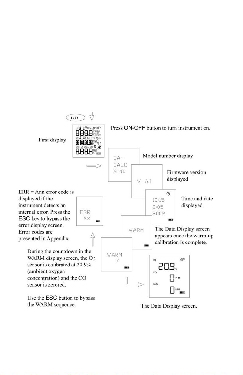
Startup
Remove the sampling probe from the flue or disconnect the sample tubing
from the sampling port. Press the ON-OFF button. The following is a
diagram of the start-up sequence, and shows screens displayed during start
up. If no errors are detected, the Data Display screen is displayed when the
sequence is complete.
While the WARM screen is displayed, the O
sensor is automatically
2
calibrated using ambient air, and the CO sensor is zeroed. At the end of the
WARM sequence (30 seconds), the pump stops and the draft sensor is
zeroed.
Figure 5. Startup Sequence
Chapter 5
Page 27

19
Characters and Display Icons
Refer to F below to identify the icons and characters that comprise the main
Data Display screen. The display icons indicate measurements made, units,
or functions performed. The icons that appear depend on the instrument
model, measurement and calculation capabilities. Refer to Chapter 1
for a
general description of your instrument model. Also refer to the next section,
“Measurements and Calculations
.”
Figure 6. LCD Display and Description of Icons
Basic Operation
Page 28

20
Measurements and Calculations
Chart of Measurements for Series CA-6100 CA-C
ALC™
Instrument Models
Measurement CA-6110 CA-6120 CA-6130 CA-6140
O2 oxygen
CO carbon
monoxide
CO2
Flue (stack) temp
TS
Air temp TA
ΔT
Excess air or
lambda
Loss (ASME)
qA (Siegert)
Efficiency
Efficiency (Siegert)
COu
COr
Draft
X X X
X X X
X X X
X X X
X X X
X X X
X X X
X X X
X X X
X X X
X X X
X X
X X
X X
Oxygen Measurement (CA-6120, CA-6130, CA-6140)
Models equipped with an O
electrochemical sensor oxygen (see table
2
above) measure oxygen concentration in the range of 0 to 25%, and
perform calculations to determine the concentration of %CO
in the
2
exhaust.
All Models with O
temperature. O
sensor are also equipped for measuring flue
2
and temperature measurements together, enable the
2
calculation of flue heat loss and efficiency.
Carbon Monoxide Measurement (CA-6130, CA-6140)
Models equipped with the CO electrochemical sensor measure carbon
monoxide in the range of 0 to 9999 PPM. Models with an O
sensor
2
too, calculate undiluted CO and CO ratio.
Measurement
CO
2
Models with an O
Flue/stack Temperature, T
sensor calculate %CO2.
2
S (CA-6120, CA-6130, CA-6140)
Flue temperature measured with sampling probe.
Chapter 5
Page 29

21
Combustion Air Temperature, TA (CA-6120, CA-6130, CA-6140)
Measurement of combustion air is determined using the temperature
probe accessory, TSI PN 3013003. In the absence of this probe, the
combustion air temperature is determined from a temperature sensor in
the instrument case.
ΔT, Temperature Difference (CA-6120, CA-6130, CA-6140)
The flue/stack temperature minus the combustion air temperature.
Excess Air or Lambda (λ) (CA-6120, CA-6130, CA-6140)
Calculations of these values are found in Appendix B
.
Loss (CA-6120, CA-6130, CA-6140)
Heat loss from the hot gases exiting the flue/stack. Includes latent heat
loss from the formation of water vapor. See Appendix B
.
qA (CA-6120, CA-6130, CA-6140)
Heat loss using the Siegert formula. See Appendix B
.
Efficiency (CA-6120, CA-6130, CA-6140)
Combustion efficiency: 100 percent minus Loss above. See
Appendix B
.
η Siegert Efficiency (CA-6120, CA-6130, CA-6140)
Combustion efficiency: 100 percent minus qA above. See Appendix B
COu, Undiluted carbon monoxide concentration (CA-6130, CA-6140)
Calculation of the CO concentration, undiluted by excess air. This
calculation requires a measurement of the O
measurement. Not available with models CA-6110 and CA-6120. Refer
to Appendix B
.
COr, CO ratio (CA-6130, CA-6140)
Ratio of CO to CO
Basic Operation
. See Appendix B.
2
concentration and CO
2
.
Page 30
22
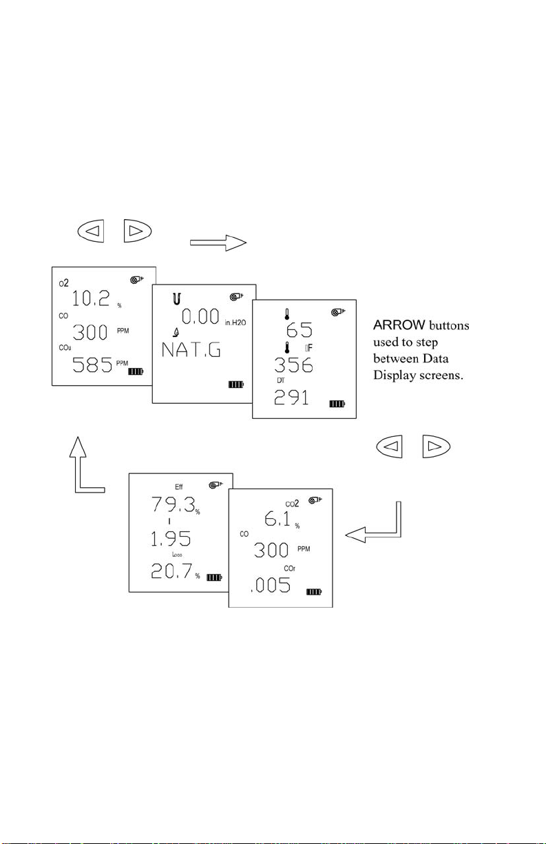
Data Display, Viewing Measurements and Calculations
Measurements and calculations are presented in the Data Display screens.
The Data Displays appear once the Startup sequence is complete as
illustrated earlier in Figure 5.
Refer to Figure 7 below. The appropriate character or icon appears above
the data shown. Select the appropriate data display using the arrow buttons.
For the Model CA-6110, only one data display screen is used, displaying
the CO concentration and Draft.
Figure 7. Example Data Displays for a
ALC Model CA-6140
CA-C
Chapter 5
Page 31

23
2. Draft regulator
4. Hot exhaust gases
Using the Sampling Probe
Gas and Temperature Measurements
Connect the sampling probe to the CA-C
Chapter 4
.
ALC™ analyzer as described in
Place the Sampling probe through a hole in the exhaust flue, following
recommendations presented below. Placement of the probe is
important, and certain considerations must be given when choosing a
sampling location.
To ensure that the gas measurements are not diluted or cooled by
outside air, place the probe before any draft damper or regulator as
illustrated in Figure 8. Tilt the probe tip up slightly so vapor
condensing in the sampling tube does not run back to the probe tip and
cool the thermocouple tip.
Important: Orient the sampling tube to ensure that the
thermocouple tip is exposed directly to exhaust flow (see
Figure 8 below).
1. Sampling probe 3. Exhaust flue
Basic Operation
Figure 8. Sampling Probe Location
Page 32

24
!
The sampling probe tip should be placed at the point of highest exhaust
gas temperature. This means at the base of the flue, before heat is lost
to the flue sidewalls, and towards the center, especially for small ducts.
If the flue/stack gas temperature is underestimated, the operating
efficiency will be overstated. When an economizer or air heater is used,
the flue/stack temperature is measured after these devices.
Cautions
Hot probe! When removed, the sampling probe will
be extremely hot. Avoid touching the probe tip, and
avoid placing the probe on or near plastic materials
such as the instrument case. These will melt.
Maintain a minimum 2” (5 cm) clearance between
the probe handle and position collar when the probe
is mounted in flue.
Empty Water Trap! Watch the water trap and
empty it frequently to prevent the possibility of
flooding the instrument. See Chapter 8
instructions.
Draft Measurement (CA-6110, CA-6140)
Whenever the pump is turned OFF, the display screen changes to display
the draft reading and the draft icon appears. Turning the pump on with the
ON/Off button again causes the draft reading to disappear.
for
Zeroing the Draft Sensor
For the most accurate draft reading, the draft sensor must be zeroed
prior to the draft measurement. To zero the draft sensor, remove the
sampling probe from the flue, or separate the sampling tube or tubes
from the draft port. Press and hold the PUMP ON/OFF button until
the display says “ZERO.” Release the button.
Saving Draft
Whenever a sample is saved using the SAVE DATA button, a draft
reading is automatically taken. For this to occur, the pump is
automatically turned off and a few seconds are allowed for th e d raft
reading to stabilize. Draft is recorded at the end of the d ata-sampling
interval.
Differential Measurement
Instruments with draft measurement capability have two ports to enable
differential pressure measurements. The left-side port is the reference
Chapter 5
Page 33

25
port. When no tube is connected, the draft measurement is referenced
to the ambient (room) pressure.
Printing to the Portable Printer and to a Computer
(All Models)
Printing to the Portable Printer
Instrument data can be output through the RS-232 serial port to the
optional portable printer. First refer to “Connecting the Optional
Portable Printer” in Chapter 4. Make sure the baud rate is set correctly.
To print the information on the Data Display, press the PRINT button.
The printer responds immediately once the button is pressed, producing
a printout of the current data. An example of this printout is shown in
Figure 9.
Saved data can be printed too. Hold the Print button down until a
countdown from three (3) begins. Release the button at zero (0), and all
saved data is printed.
Printing individual saved data samples is described in the next section,
“Handling Data
.”
Printing to a Computer
Use the PRINT button to output data to a computer as well as to the
portable printer. Refer to “Connecting to a Computer
” in Chapter 4.
Data transferred to a computer is the same as that output to a printer
(see Figure 9); however, it is formatted differently and uses the
®
Windows
character set rather than DOS characters. You will need to
set appropriate COMM MENU option before sending data to the
computer. Refer to the Chapter 6, “MENU Options
.”
Data can be downloaded to a terminal emulator program such as the
HyperTerminal, which accompanies the Windows
®
operating system
program. Look for HyperTerminal in the Accessories folder. In
HyperTerminal, use the Capture Text option from the Transfer
menu for recording instrument data.
Your instrument comes configured with the following communications
protocol.
®
Windows is a registered trademark of Microsoft Corporation.
Basic Operation
Page 34

26
Communications Protocol
Baud rate 1200 (default)
Data bits 8
Parity None
Stop bit 1
Flow None
-------------------------------MODEL: 6130
SERIAL: 55030026
---------------------------------Current Data
--------------------------------DATE: 01/16/06
TIME: 15:00:18
Fuel: Nat G
Fuel Parameters:
Carbon wt.: 75.0 %
Hydrogen wt.: 25.0 %
CO2 max vol.: 11.8 %
Sulfur wt.: 0.0 %
kBTU/lb: 23.8
Moisture: 0.0 %
O2: 6.0 %
CO: 5 PPM
COu: 7 PPM
CO2: 8.4 %
COr : NA
TA: 70 °F
TS: 300 °F
TS-TA: 230
EA: 16 %
Loss: 16 %
Effc: 84 %
Figure 9. Example Printout
Chapter 5
Page 35

27
Handling Data
Saving Data
Up to twenty (20) separate measurements can be made and saved to the
instrument memory. Data is saved from the Data Display screen by
pressing the SAVE DATA button. When SAVE DATA is pressed,
measurements are sampled and averaged over the interval set in the
INT.S MENU option
described in Chapter 6. As data is sampled, the
sample number is displayed, and the save data icon blinks.
Note: The pump turns off while the draft is measured and saved.
Figure 10. Saving Data Diagram
Basic Operation
Page 36

28
CLEAR Data
Press the CLEAR DATA button, from the Data Display screen, to erase
data Samples saved in instrument memory. To prevent accidentally
erasing all your data, the CLEAR DATA button must be held while the
instrument counts down from three (3). When the instrument displays
zero, release the button and the all data cleared. If the button is held
longer, nothing is cleared.
To erase the last Sample only, release the CLEAR data button before
zero is displayed, during 3, 2, or 1.
Figure 11. Clearing Saved Data
Chapter 5
Page 37

29
REVIEW Data Samples
Press the REVIEW DATA button briefly to recall saved Samples. The
number of the last Sample appears. Select the specific data Sample you
wish to view using the ARROW buttons and press ENTER. When the
Sample is displayed, use the ARROW buttons to step through the
measurement screens. Review the diagram in Figure 12. You can
average data Samples as described in the next section.
Printing
To print individual saved Samples, press the print button while the
saved Sample is shown. To print all saved Samples, hold the PRINT
button down until a countdown from three (3) begins. Release the
button at zero, (0) and all saved Samples are printed.
Figure 12. Review Saved Data
Basic Operation
Page 38

30
Averaging Saved Samples
To average all your saved Samples, press and hold the REVIEW DATA
button while in the Data Display screen. Hold the button for three seconds.
The screen blanks during this interval. The X-bar icon which appears
indicates that the data presented is an average of all Samples. See
Figure 13.
Figure 13. Display of Average of Samples
Chapter 5
Page 39

Chapter 6
MENU Options
The Series CA-6100 CA-CALC™ instrument has a variety of user selectable
parameters, available as MENU options. The user-selectable MENU options
are shown in the schematic below. Press ENTER to access the MENU
options from the Main Data Display screen. View the MENU options by
pressing using the ARROW buttons. Once the screen of interest is
displayed, press the ENTER button again to choose the MENU option.
Refer to Figure 14, which shows the MENU options.
Figure 14. Menu Option
31
Page 40

32
LITE Menu Option
Select the backlight option as ON, OFF or AUTO. Auto turns the backlight
on for 60 seconds whenever a button is pressed. Refer to Figure 14, which
shows the LITE menu option.
FUEL Menu Option
Use the FUEL option to select from seven preset U.S. fuels or six Siegert
fuels, or select the USER fuel. The fuels parameter list presented (U.S. or
Siegert), is determined by the LOSS selection (Loss or qA respectively). For
more on fuels, refer to the fuel parameters, FP MENU option in this chapter,
and information in Appendix B
. Refer to Figure 15, which shows the FUEL
menu options.
Figure 15. FUEL Options
Chapter 6
Page 41

33
UNIT Menu Option (Changing Units)
It is possible to display data in different measurement un its as indicated in
the table below.
Optional Units
Measurement UNIT Options
TEMP (temperature) Degrees F Degrees C
GAS (*CO concentration) PPM mg/m3
PRES (draft pressure) In. H2O mbar hPa mm H2O
EA (excess air) % EA λ (Lambda = %EA/100 + 1)
LOSS (flue gas heat loss) Loss (ASME) qA (Siegert)
DECI Period, or comma f or decimals
DATE Month/day or day/month format option
To change units, press the ENTER button from the Data Display screen.
Using the ARROW buttons, find UNIT from the MENU options. Continue
using the ARROW buttons to find an option and ENTER to activate it.
Refer to the example below which diagrams changing units. In this example,
CO units are changed.
Figure 16.
Choosing Units.
Example; Setting
the GAS Display
Units.
Menu Options
Page 42

34
INT.S MENU Option
This option enables you to change the sampling interval over which data is
averaged and saved. Use the ENTER button to select. Use the ARROW
buttons to choose the sampling interval from the following options 1, 5, 10,
15, 20, 25, and 30. These represent the number of discrete data values taken
each second and averaged. Use the SAVE DATA button to begin sampling.
TIME MENU Option (Set Time and Date)
Press the ENTER button when the TIME MENU item is displayed. Use the
ARROW buttons to select the field to be changed. The field will blink as it
is highlighted by the ARROW button. To change, press ENTER again. Use
the ARROW buttons to increase or decrease the value selected. Press
ENTER to install the new value. Press ESC to abort and return to the
previous screen.
Time or
and Date
fields
HR:MN
MM.DD
2 0 Y Y
HR:MN
DD.MM
2 0 Y Y
CAL MENU Option
The CAL option is used for performing calibrations of the on-board sensors.
When this option is chosen using the ENTER button, characters and icons
associated with the installed sensor will be displayed, one at a time. Press an
ARROW button and scroll through the options until the desired sensor for
calibration appears. Press ENTER to begin the calibration process. Refer to
Figures 17, 18, and 19, for schematic representations for calibration of the
electrochemical sensors, draft sensor and temperature sensors.
Gas Sensor Calibration (CA-6120, CA-6130, CA-6140)
O
2
Select CAL from the MENU options using the ENTER button. Select
icon from the icons displayed using an ARROW button and
the O
2
press ENTER. Attach the zero gas (nitrogen, N
as described in Chapter 7, “Setup for Gas Calibration
press ENTER to begin the zero calibration. Once complete, the SPAN
calibration screen appears. The O
the ARROW buttons. If room air is used as the calibration gas, do not
change the 20.9% value displayed.
concentration can be adjusted using
2
) to the sampling probe
2
.” When ready,
Chapter 6
Page 43

35
Use the ARROW buttons to match the calibration gas concentration. If
the ambient air is used, make sure the setting is 20.9% as shown.
Press ENTER button to begin the SPAN calibration.
Figure 17. O2 Sensor Calibration Sequence
Menu Options
Page 44
36
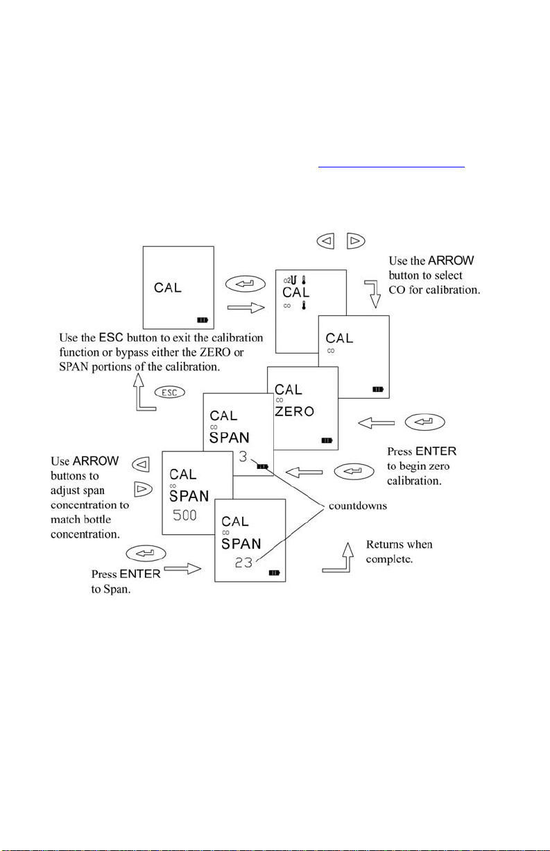
CO Sensor Calibration (CA-6110, CA-6130, CA-6140)
Select CAL from the MENU options by pressing ENTER. Select the
CO icon from the icons displayed using an ARROW button and press
ENTER. For the zero calibration, find a location free of CO. When
ready, press ENTER to begin the zero calibration. Once complete, the
SPAN calibration screen appears. Connect your calibration gas to the
sampling probe as described in Chapter 7, “Setup for Gas Calibration.
Adjust the CO concentration in the span screen, using the ARROW
buttons, so it matches your calibration gas bottle concentration. Press
the ENTER button to start the calibration.
”
Figure 18. CO Calibration
Chapter 6
Page 45

37
Draft Calibration (CA-6110, CA-6140)
Span calibration of the draft sensor is normally not required. The draft
sensor should be routinely zeroed however, to compensate for the
effects of temperature on sensor signal, and to correct for normal drifts
in sensor zero voltage over time. As described earlier in the manual,
zeroing the sensor is achieved simply by holding the pump ON/OFF
button down for three seconds. This should be done prior to any
pressure measurement. This is especially important when the draft
pressure is small.
The schematic below outlines the steps in performing a draft calibration.
As with other calibrations, select the draft icon using the arrow buttons.
Begin the calibration by pressing the ENTER button to perform a
calibration zero. When the zero is complete, use the arrow buttons to
select your supply reference pressure. Press ENTER to initiate the Span
calibration. Both plus and minus pressures are calibrated by applying
the same positive pressure to both the right then left draft sample ports
in turn.*
Figure 19. Draft Calibration
Menu Options
Page 46

38
Temperature Calibration (CA-6120, CA-6130, CA-6140)
Calibration of the thermocouple temperature sensors is not
recommended. Thermocouple sensors are very repeatable, so even if a
replacement is required, or a combustion air temperature probe is
purchased as an accessory, it is unnecessary to calibrate it. Calibration
of a thermocouple probe has value if a narrow temperature range is
used, and calibration is preformed in that range. The burden is left to
you to provide an accurate temperature reference. Refer to the steps
diagramed below if calibration of a thermocouple is desired.
Figure 20. CO Calibration
Chapter 6
Page 47
39
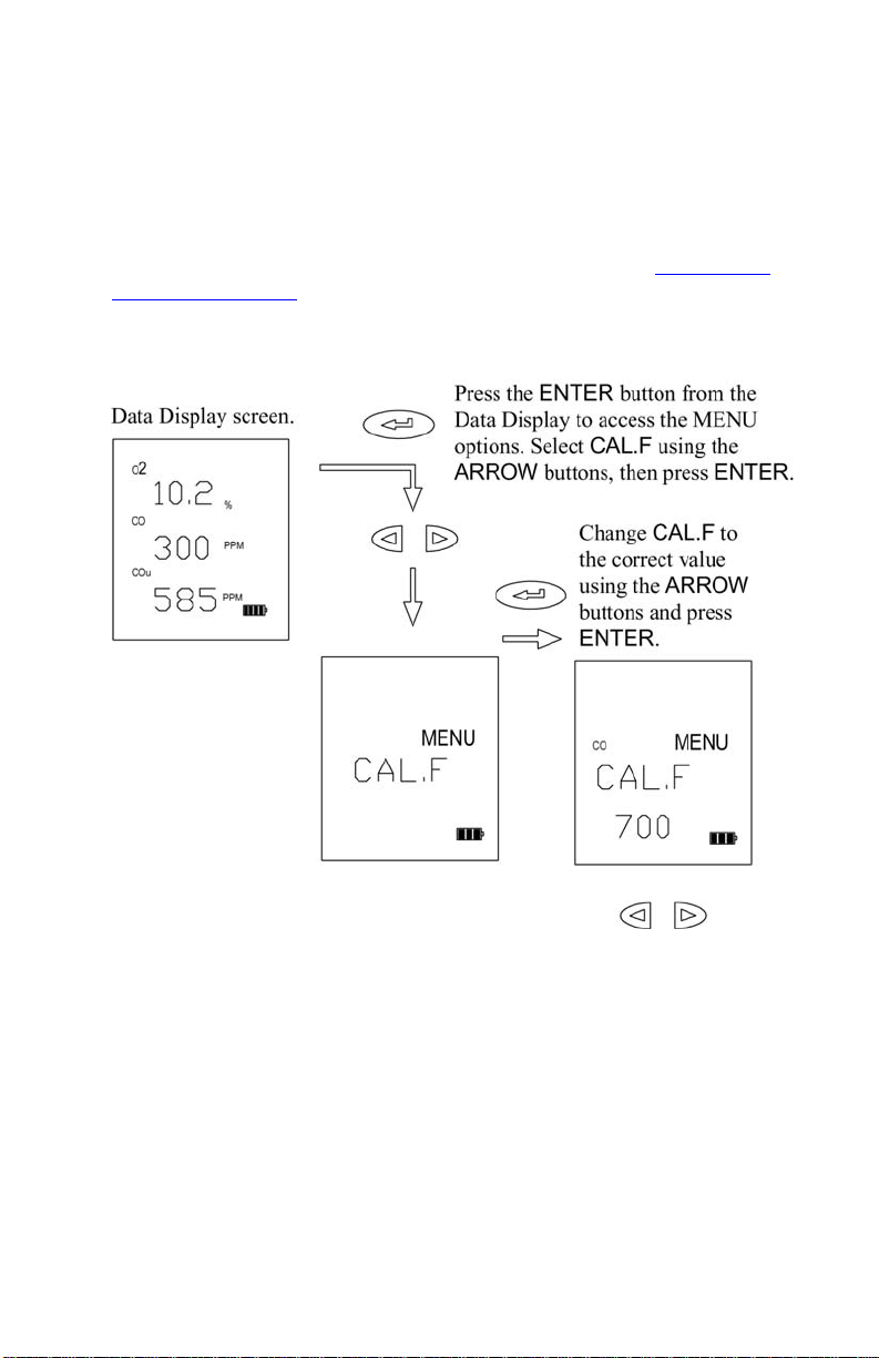
CAL.F MENU Option—Setting the Calibration Factor
When you install a replacement CO sensor from TSI, you will enter a new
calibration factor. This factor is determined by a sensor calibration at the
factory.
After installing your new sensor, as described in Chapter 8, “Maintenance
and Troubleshooting,” find the calibration factor sheet. Use the MENU
option CAL.F, and enter calibration factor provided. Refer to the details
outlined in the schematic below.
Figure 21. Setting the Calibration Factor
Menu Options
Page 48

40
BAUD Rate MENU option
Baud rate can be set to match your computer or portable printer. Your
instrument is delivered with a default baud rate of 1200.
Baud rate values are displayed in the BAUD rate option divided by 1000.
The following baud rates can be set. 1.2 (1200), 2.4 (2400), 4.8 (4800),
9.6 (9600), 19.2 (19200).
To set the baud rate follow the steps outlined in the schematic shown below
in Figure 22.
Figure 22. Setting the Baud Rate
Chapter 6
Page 49

41
COMM MENU Option—Set the Output Communications Device
Your CA-C
ALC™ analyzer transfers current or saved data to a serial printer
or computer The COMM MENU option is used to select the device that you
want to communicate with.
To set the device, follow the steps outlined in the schematic shown below in
Figure 23.
Figure 23. Setting the Data Output Device
Menu Options
Page 50

42
FP MENU Option—Fuel Parameters (CA-6120, CA-6130, CA-6140)
U.S. Fuel Parameters
For U.S. fuels, and U.S. Fuel Parameters to be displayed, the fuel heat
LOSS selection must be set to Loss, not qA. Refer to the section
“UNIT Menu Option (Changing Units)
” in this chapter.
For calculations of flue losses, maximum %CO
, fuel composition and
2
fuel heat content are used. These are the Fuel Parameters. In your CA-
ALC™ analyzer, U.S. fuel parameters are the carbon and hydrogen
C
content, moisture content, sulfur content, and maximum %CO
, C2MX.
2
Refer to the diagrams (Figures 24 and 25) and table below, for
information on viewing and changing fuel parameters.
Figure 24. Fuel Parameters for U.S. Fuels
Chapter 6
Page 51

43
Your CA-CALC™ analyzer has parameters for seven common U.S. fuels
in instrument memory. Fuel parameters for these fuels can be changed,
if you know, for example, that your fuel has a different composition
than that stored. The instrument fuel parameters values are presented in
Appendix B, with additional technical information.
Fuel Parameter Descriptions for U.S. Fuels
Fuel Parameter Description
C % carbon by weight
H % hydrogen by weight
H2O % water content by weight
S % sulfur by weight
C2MX CO2 max %
KBTU Heating value in kiloBTUs/lb
FP Fuel Parameters for Siegert Calculation—Siegert Fuel Parameters
For the Siegert fuels and Siegert Fuel Parameters to be displayed, the fuel
heat LOSS selection must be set to qA, not Loss. Refer to the section UNIT
Menu Option (Changing Units)” in this chapter.
The Siegert value for flue loss, given the designation qA, is used
widely in Europe. Two coefficients are used in the Siegert formula for
flue loss, derived from typical fuel compositions. These are given the
designations, A2 and B.
The default Siegert coefficient values in your CA-C
ALC™ analyzer, are
those used in Germany. Siegert coefficients used in other countries
may be different, reflecting differences in local fuel compositions.
Note: A2 is sometimes defined differently. A2 values entered by the user
must be appropriate for the Siegert equation presented in
Appendix B
.
Figure 25 diagrams the steps in changing the Siegert fuel parameters.
Menu Options
Page 52

44
Figure 25. Changing Fuel Parameters for
Siegert Fuels
LANG MENU Option
Use this option to select between the following languages: E English,
D German, N Dutch, FI Finish, I Italian or S Swedish. English is the
language (default) initially installed on the instrument.
When the language is changed, instrument settings are automatically
changed too. Refer to Chapter 4 “Default Instrument Settings
” for more
information on this feature.
Chapter 6
Page 53

Chapter 7
Setup for Gas Calibration
The Calibration Setups
Note: To perform your gas sensor calibration, you will also need to refer
back to Chapter 6, and the section, “CAL MENU Option
CO and O
accuracy of these gas measurements. Gas sensors do drift over time,
depending upon the operating environment and gas exposure history.
With the proper equipment, such as that shown in the figures below, it is
easy to calibrate your CA-C
wish, you may also return your instrument to TSI for a new factory
calibration.
The equipment needed to calibrate individual gas sensors can be purchased
from TSI as calibration kits. Model numbers for these kits are found in
Chapter 2, “Unpacking
calibration system. Two calibration setups are presented in Figures 26 and
27. A brief discussion of these calibration setups is presented in the
following section.
gas sensors can be calibrated periodically to maintain the
2
ALC™ analyzer gas sensors. However, if you
.” You may also elect to put together your own
.”
45
Page 54

46
Figure 26. Calibration with TSI Calibration Kit
A TSI supplied calibration kit (Figure 26) uses a demand flow regulator to
supply gas to the CA-C
ALC™ analyzer in response to the draw of the
instrument sampling the pump. If a conventional regulator and valve are
used (Figure 27), the setup supplies gas to the instrument using a tee to a
bleed-off extra gas. This prevents a forced flow at the instrument inlet. The
bead-type flow meter depicted in the figure is used to verify there is extra
flow (.5 to 2 L/min recommended). Extra flow is required to prevent room
air from being drawn in, diluting the sample.
Chapter 7
Page 55

47
Figure 27. Alternative Calibration Setup
Setup for Gas Calibration
Page 56

48
(This page intentionally left blank)
Chapter 7
Page 57

Chapter 8
Maintenance and Troubleshooting
For additional troubleshooting information, please visit TSI’s website
http://combustion.tsi.com.
Emptying Water Trap
Refer back to Figure 2 showing the water trap in the sample line, and to
Figure 28 below. Liquid water forms in the first chamber of the water trap as
gases are sampled from the flue. The water trap is designed so even when
shaken, or when its orientation is changed, water does not pass to the second
chamber. The water level must remain below the level depicted in the figure,
however.
To empty the water trap:
1. First separate it from the sampling tube by pulling the tube ends off the
barbs on the end caps.
2. Remove the probe side end cap by pulling outward with a twisting
motion.
3. Pour out the water.
4. Replace the end cap and re-install the trap.
Important: Make sure the water trap is oriented so that end-cap 1
below is toward the instrument.
Changing the (optional) Water Trap Filter
Identify the water trap filter (refer to Figure 28). This filter is designed to
remove soot particles before they contaminate the instrument. The filter can
be removed for cleaning or replacement by following these steps:
1. Remove the instrument side end cap by pulling it out with a twisting
motion.
2. Grasp the filter using a needle-nose pliers and pull it out.
3. To clean the filter, remove the bulk of the soot by tapping the filter. The
soot may be removed by rinsing with water or isopropyl alcohol. The
effectiveness of the rinse depends on the soot composition—is it dry or
oily. Avoid rubbing, which may drive contaminates into the filter
causing permanent plugging.
49
 Loading...