

Page 1

TTP-244M Pro / TTP-342M Pro
TTP-244ME Pro / TTP-342ME Pro
USER’S
MANUAL
THERMAL TRANSFER / DIRECT THERMAL
BAR CODE PRINTER
Page 2

i
CE CLASS A
EN55022:2006+A1:2007
EN50024:1998+A1:2001+A2:2003
EN61000-4-2:2008, EN61000-4-3: 2008, EN61000-4-4: 2004
EN 60950-1:2006+A11:2009 (LVD)
GB9254-2008 (CLASS A)
GB4943-2001
GB17625.1-2003
此为A 级产品,在生活环境中,该产品可能会造成无线电干扰,
在这种情况下,可能需要用户对干扰采取切实可行的措施。
Copyright Information
© 2011 TSC Auto ID Technology Co., Ltd,
The copyright in this manual, the software and firmware in the printer described
therein are owned by TSC Auto ID Technology Co., Ltd, All rights reserved.
Windows is a registered trademark of Microsoft Corporation.
All other trademarks are the property of their respective owners.
Information in this document is subject to change without notice and does not
represent a commitment on the part of TSC Auto ID Technology Co. No part of
this manual may be reproduced or transmitted in any form or by any means, for
any purpose other than the purchaser’s personal use, without the expressed
written permission of TSC Auto ID Technology Co.
Agency Compliance and Approvals
A급기기
(업무용 정보통신기기)
이 기기는 업무용으로 전자파 적합등록을 한 기기이오니, 판매자 또는 사용자는 이 점을
주위하시기 바라며, 만약 잘못 판매 또는 구입하였을 때에는 가정용으로 교환하시기 바랍니다.
Page 3

ii
CONTENTS
1. PRODUCT INTRODUCTION.............................................................. 1
2. GETTING STARTED .......................................................................... 2
2.1 Equipment Checklist ........................................................................................ 2
2.2 Printer Parts ..................................................................................................... 3
2.3 Buttons and Indicators ..................................................................................... 6
3. SET UP .............................................................................................. 8
3.1 Setting up the Printer ....................................................................................... 8
3.2 Loading the Ribbon .......................................................................................... 9
3.3 Loading the Label .......................................................................................... 13
3.4 Loading Media in Peel-off Mode (Option) ...................................................... 16
3.5 Loading Media in Cutter Mode (Option) ......................................................... 18
4. POWER-ON UTILITIES ................................................................... 19
4.1 Self Test Utility ............................................................................................... 19
4.2 Gap Sensor Calibration Utility ........................................................................ 22
4.3 Printer Initialization ........................................................................................ 23
5. DIAGNOSTIC TOOL ......................................................................... 24
5.1 Start the Diagnostic Tool ................................................................................ 24
5.2 Printer Function .............................................................................................. 25
6. TROUBLESHOOTING ...................................................................... 26
7. MAINTENANCE ................................................................................ 27
REVISE HISTORY ................................................................................ 28
APPENDIX A MENU CONTROL FLOWCHART (OPTION) ................... 1
Page 4

1
1. PRODUCT INTRODUCTION
Thank you very much for purchasing this bar code printer. The attractive printer
delivers superior performance at an economical price. Both powerful and easyto-use, this printer is your best choice.
The printer offers both thermal transfer and direct thermal printing at user
selectable speeds: either 1.5, 2.0, 3.0 and 4.0 IPS (Inch Per Second) for 203 DPI
model; 1.0, 1.5 and 2.0 IPS for 300 DPI model. It can accept a wide range of
media, including roll feed, die-cut, and fan-fold labels for both thermal transfer
and direct thermal printing. All of the most frequently used bar code formats are
available. Fonts and bar codes can be printed in any one of the four directions.
This printer provides a choice of five different sizes of alphanumeric fonts. By
using font multiplication, an even greater range of sizes is possible. Smooth fonts
can be down-loaded from the user friendly, Windows labeling software. In
addition, this printer is capable of independently executing BASIC programming
functions, including arithmetic, logical operation, loop, flow-control and file
management, among others. This programming capability provides the greatest
efficiency in label printing.
Page 5

2
2. GETTING STARTED
This printer has been specially packaged to withstand damage in the shipping
process. However, for fear that unexpected damage might occur, upon
receiving the bar code printer, carefully inspect the package and the device. In
case of evident damage, contact the carrier directly to specify the nature and
extent of the damage. Please retain the packaging materials in case you need
to reship the printer.
2.1 Equipment Checklist
One bar code printer unit
One ribbon paper core for ribbon rewind spindle
Two ribbon supply/rewind spindle (2 pcs)
One USB interface cable
One power cord
One Windows labeling software/ Windows driver CD disk
One quick start guide
Separately purchased items may also be included. These additional items may
include:
Labels
Ribbons
Stand-alone keyboard
Cutter module
Peel-off module
If any parts are missing, please contact the Customer Service Department of
your purchased reseller or distributor.
Page 6

3
Front View
1. Printer cover/ Release handle
2. Label dispense opening
3. Liner opening (Option function)
4. MENU button (Option for E series)
5. PAUSE/ SELECT button
6. FEED/ SET button
7. Error indicator
8. On-line indicator
9. LCD display (Option for E series)
10. Power indicator
1 2 3 4 5
6
7
8
9
10
2.2 Printer Parts
Page 7

4
Interior View
1. Ribbon supply spindle
2. Label roll guard
3. Label supply spindle
4. Ribbon rewind spindle
5. Sensor switch
6. Print head release lever
7. Front panel
8. Printer cover
9. Print head
10. Platen roller
11. Media sensor
12. Adjustable label guide
1 2 3
4
5
6 7 8 9
10
11
12
Page 8

5
Rear View
1. Centronics interface (Option for E series)
2. Ethernet interface (Option)
3. USB interface
4. Label insert opening (For use with external labels)
5. RS-232C interface connector
6. SD card socket
7. Power switch
8. Power cord socket
Note: The interface picture here is for reference only. Please refer to the
specification for the interfaces availability.
1
2 3 4
5
6
7
8
Page 9

6
2.3 Buttons and Indicators
POWER Indicator
The green POWER indicator illuminates when the power switch is turned on.
ON-LINE Indicator
The green ON-LINE indicator illuminates when the printer is ready to print. When
the PAUSE button is pressed, the ON-LINE indicator will be flash.
ERROR Indicator (Error/Paper Empty)
The red ERROR indicator illuminates in the event of a printer error, such as
paper empty, ribbon empty, out of memory, and so forth. For a full list of error
messages, please refer to Section 4.2, Troubleshooting Guide.
MENU Button (Option function for E series)
Provided with a built-in menu, the printer allows the user to directly set printing
parameters or view printer status on the LCD display panel. To enter the Menu
mode, press the MENU button. Press the button over again to proceed form one
menu item to another or to revert to the original Ready status. The menu is
comprised of these major items: Printer Info, File List, Memory Info,
Date/Time, and Printer Setup. Each of said items, in turn, is made up of a
number of sub-items, which can be selected by pressing the SELECT button, or
viewed or set by pressing the SET button. Refer to Appendix for the structure
and operation logic of the menu.
PAUSE/SELECT Button
This button combines two functions: PAUSE if the printer is in the Ready status,
or SELECT if in the Menu mode.(Option function for E series)
The PAUSE button allows the user to hold a print job and then resume the
printing with a second depression of the button. By pressing the PAUSE button:
(1) the printer stops at the completion of printing of the current label, (2) the
PAUSE LED flashes, and (3) the printer holds all data in memory. This allows for
trouble-free replacement of label stock and thermal transfer ribbon. A second
depression of the PAUSE button will restart the printer.
Note: If the PAUSE button is held down for more than 3 seconds, the
printer will be reset and all data of the previous printing job will be
lost.
Page 10

7
The SELECT button allows the user select for the sub-item to be processed.
Once the sub-item has been selected, the user can change its setting by
pressing the SET button. (Option function for E series)
FEED/SET Button
As does the PAUSE/SELECT button, this button also has dual functions: FEED
and SET.
Press the FEED button for label to advance to the next print position.
Press the SET button to change parameter settings or view printer status on the
LCD screen. (Option function for series)
Page 11

8
3. SET UP
3.1 Setting up the Printer
1. Place the printer on a flat, secure surface.
2. Make sure the power switch is off.
3. Connect the printer to the computer mainframe with the provided printer cable.
4. Plug the power cord into the AC power cord socket at the rear of the printer,
and then plug the power cord into a properly grounded receptable.
Note: Please switch OFF printer power switch prior to plug in the power cord to printer
power jack.
Page 12
9
3.2 Loading the Ribbon
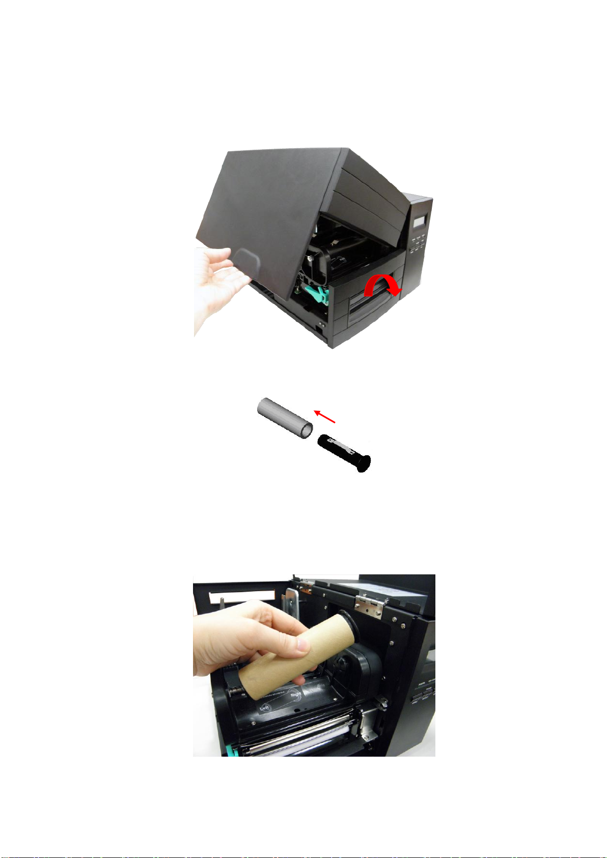
1. Open the printer cover and front panel.
2. Place an empty paper core onto the ribbon rewind spindle.
3. Insert the left side first. Mount the ribbon rewind paper core on the front hubs.
Please be noted that the bigger hub side with 4 ribs must be installed toward
the right side of ribbon mechanism.
Page 13
10
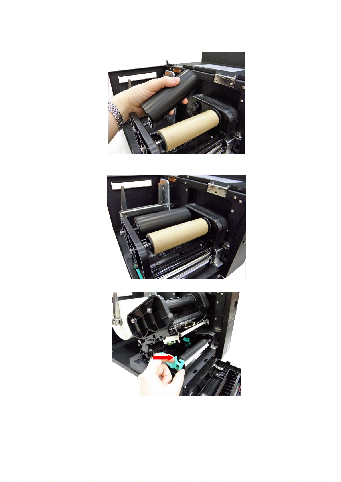
4. Install a ribbon on the ribbon supply spindle. Mount the ribbon supply spindle
on the rear hubs. Insert the left side first.
5. Please be noted that the bigger hub side with 4 ribs must be installed toward
the right side of ribbon mechanism.
6. Disengage the printer carriage by pulling the print head release lever.
Page 14
11
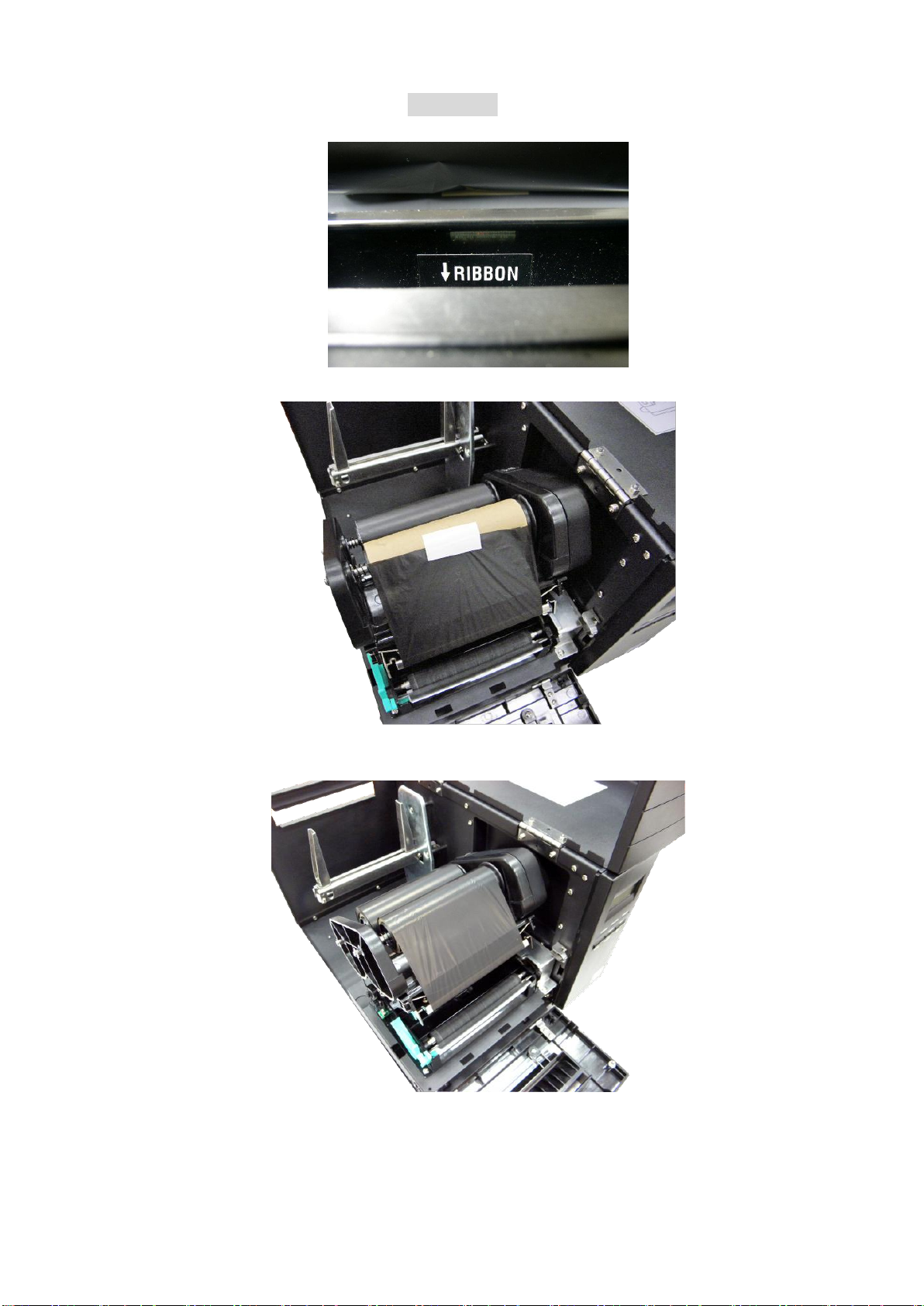
7. Following the direction of the RIBBON label, pull the ribbon leader to the
front from beneath the printer carriage.
8. Attach the ribbon leader to the ribbon rewind paper core (with a tape).
5. Rotate the ribbon rewind roller until the ribbon overlaps the ribbon leader and
stretches tight.
6. Engage the printer carriage.
7. Close the printer cover and press the FEED button until the green ON-LINE
LED illuminates.
Page 15

12
Note:
When switched on, the printer will automatically detect whether ribbon is
installed to set printer to direct thermal or thermal transfer mode. As such,
to use thermal transfer mode, be sure to install the ribbon, the label, and
engage the ribbon mechanism before you switch on the printer. To use
direct thermal mode, install the label and engage the ribbon mechanism
before switching on the printer.
Please refer to videos on TSC YouTube or driver CD.
Page 16
13
3.3 Loading the Label
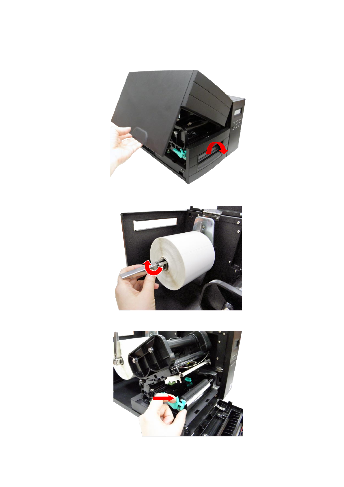
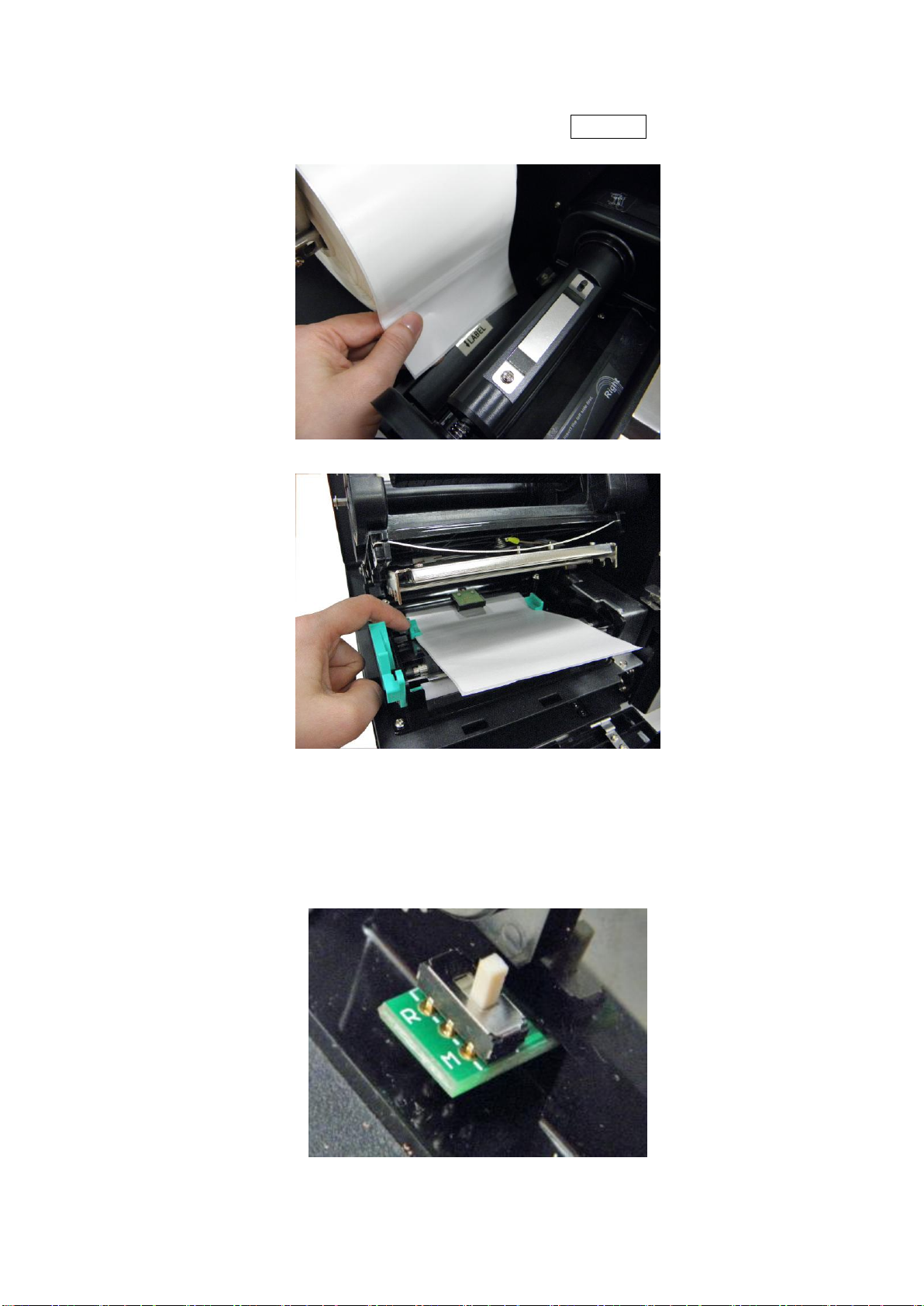
1. Open the printer cover and front panel.
2. Lower the label roll guard to the horizontal position, slide the label stock into
label roll spindle, and then flip back the label roll guard.
3. Disengage the printer carriage by pulling the print head release lever located
to the left side of the platen.
Page 17
14
4. Install the label so that it goes (when using an external label roll mount:
through the label feed slot) in the direction of the LABEL label and under the
ribbon mechanism to lay upon the platen.
5. Adjust the label guide to fit the width of the media.
6. Engage the printer carriage.
7. Wind the label roll until it becomes adequately stretched for the intended
purpose.
8. Select the using label type by sensor switch.
“M” for single column label
“R” for double column label
9. Close the printer cover and front panel.
Page 18

15
10. Use “Diagnostic Tool” to set the media sensor type and calibrate the selected
sensor. (Start the “Diagnostic tool” Select the “Printer Configuration” tab
Click the “Calibrate Sensor” button) Please refer to the section 4.
Note:
Please calibrate the gap/black mark sensor when changing the media.
When the printer is out of ribbon or label, the ON-LINE LED will not come
on and the ERROR LED will flash. Reload the ribbon or media without
turning off the printer. Press the FEED button a few times until the ONLINE LED illuminates, the printing job will be resumed without data loss.
Please refer to videos on TSC YouTube or driver CD.
Page 19
16
Label
Liner
Platen
White peel-off
roller
3.4 Loading Media in Peel-off Mode (Option)
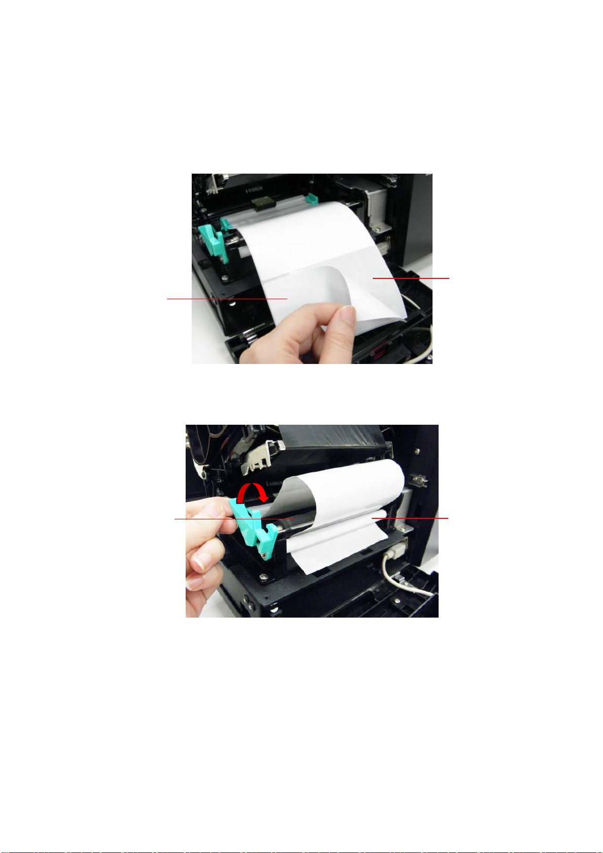
1. Please refer to section 3.3 to loarding the media and to calibrate the sensor
first.
2. Remove the foremost one or two labels from the liner.
3. Pull the print head release lever to feed the liner between the platen and the
white peel-off roller.
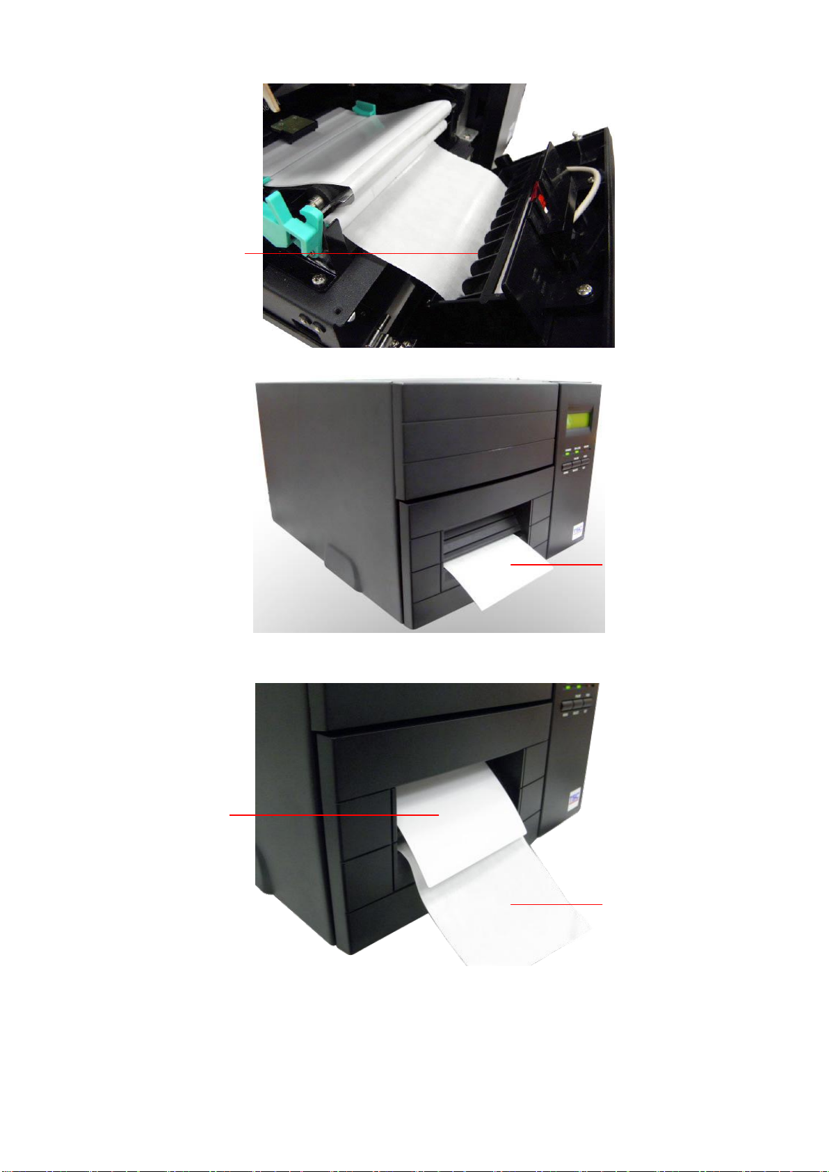
4. Feed the liner through the liner opening in the front panel.
Page 20
17
Liner
opening
Label
Liner
Liner
5. Close the print head, front panel and printer cover.
6. Set the “post-print action” to “peel”. Peeling will automatically start. Press the
FEED button to test.
Note: Please calibrate the gap/black mark sensor when changing media.
Page 21
18
3.5 Loading Media in Cutter Mode (Option)
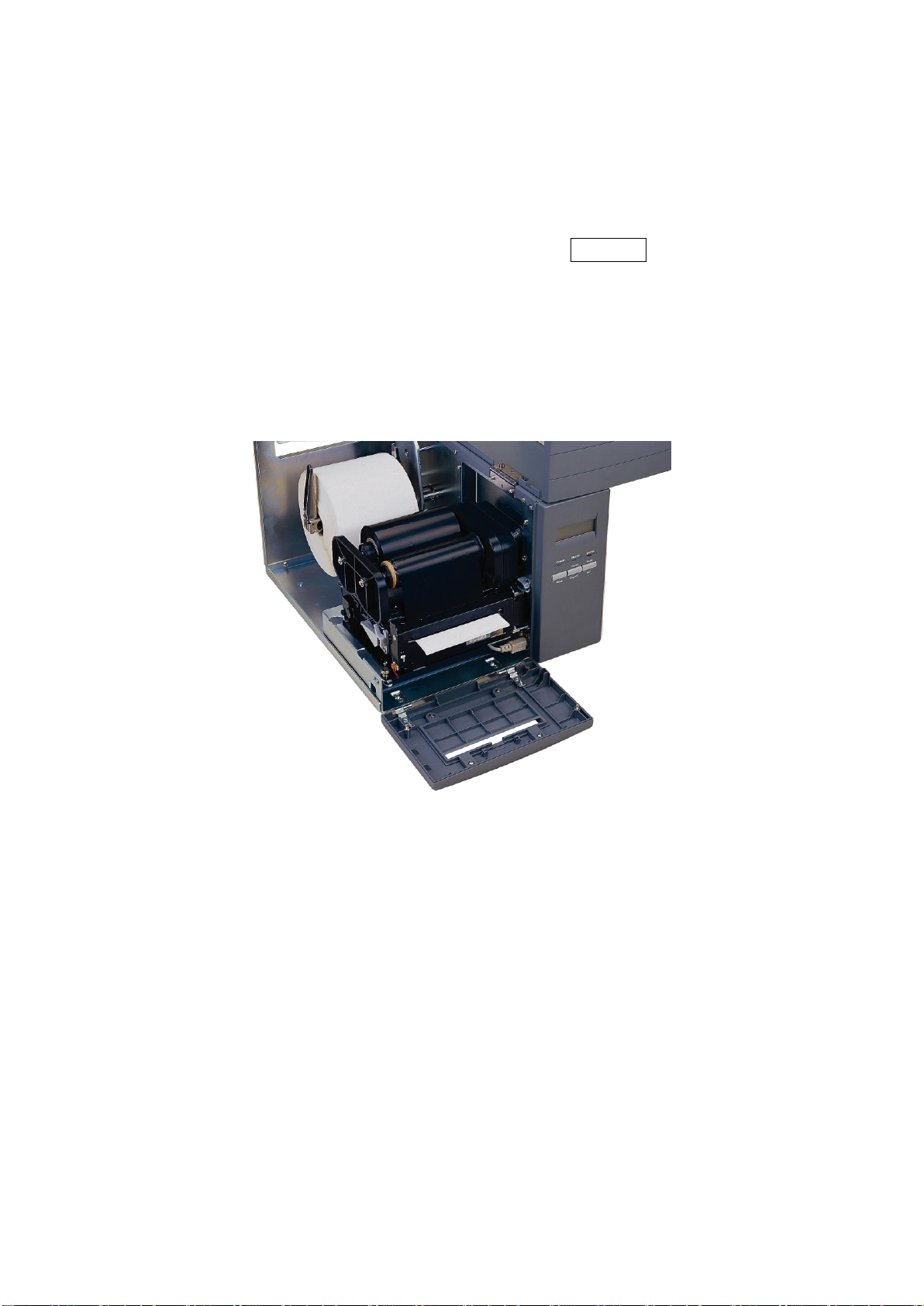
1. Please refer to section 3.3 to loarding the media.
2. Install the label so that it goes (when using an external label roll mount:
through the label feed slot) in the direction of the LABEL label and under the
ribbon mechanism. Feed the label through the cutter opening.
3. Adjust the label guide to fit the width of the media.
4. Engage the printer carriage.
5. Close the printer cover and front panel.
6. Use “Diagnostic Tool” to set the media sensor type and calibrate the selected
sensor. And set the “post-print action” to “cutter”.
Note:
Please calibrate the gap/black mark sensor when changing the media.
When the printer is out of ribbon or label, the ON-LINE LED will not come on
and the ERROR LED will flash. Reload the ribbon or media without turning off
the printer. Press the FEED button a few times until the ON-LINE LED illuminates,
the printing job will be resumed without data loss.
Cutter module specification:
− Rotary regular cutter
− Paper thickness: Min. 0.12mm, 500,000 cuts
Max. 0.20mm, 250,000 cuts
− Rotary heavy duty cutter
− Paper thickness: Min. 0.12mm, 500,000 cuts
Max. 0.25mm, 250,000 cuts
Except for the linerless cutter, all regular/heavy duty/care label cutters DO NOT
cut on media with glue.
Page 22
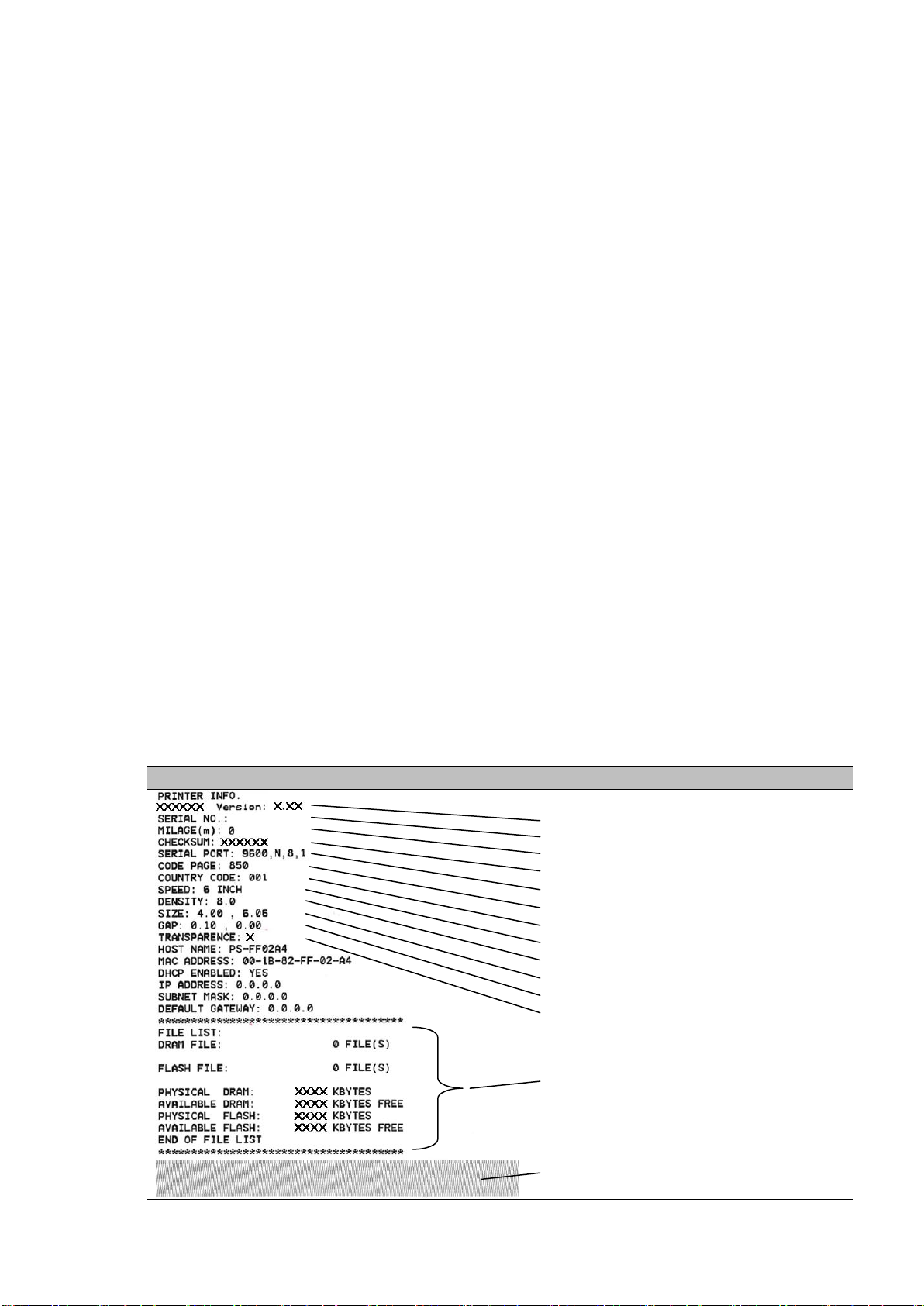
19
Self-test printout
Model name and F/W version
Serial no.
Printed mileage (meter)
Firmware checksum
Serial port configuration
Code page
Country code
Print speed (inch/sec)
Print darkness
Label size (inch)
Gap distance (inch)
Gap/black mark sensor sensitivity
Numbers of download files
Total & available memory space
Print head check pattern
4. POWER-ON UTILITIES
There are three power-on utilities to set up and test the printer hardware. These
utilities are activated by pressing the FEED or PAUSE button and turning on the
printer power simultaneously. The utilities are listed below:
1. Self test
2. Gap sensor calibration
3. Printer initialization
4.1 Self Test Utility
Install the label first. Press the FEED button and then turn on the printer power.
Do not release the FEED button until the printer feeds labels. The printer performs the following:
1. Calibrate label pitch
2. Print out thermal print head check pattern
3. Print the internal settings
4. Enter dump mode
To initiate the self test mode, hold down the FEED button and activate the printer
power simultaneouly. The printer will calibrate the label length. If the label gap is
not detected within 7", the printer stops feeding labels and the media is regarded
as continuous paper. In self test, a check pattern is used to check the performance of the thermal print head. Following the check pattern, the printer prints its
internal settings as listed below:
Page 23
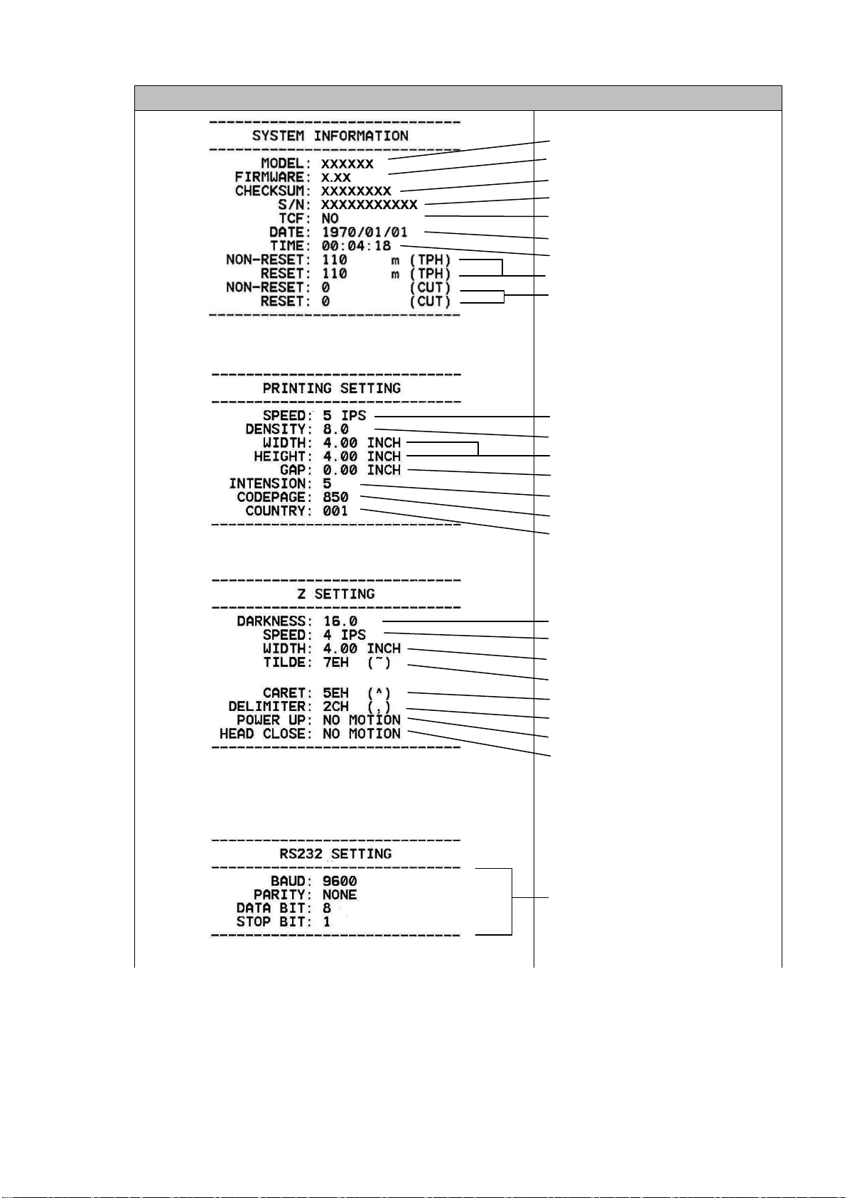
20
Self-test printout (with printer firmware V7.0 and later version)
Model name
F/W version
Firmware checksum
Printer S/N
TSC configuration file
System date
System time
Printed mileage (meter)
Cutting counter
Print speed (inch/sec)
Print darkness
Label size (inch)
Gap distance (inch)
Gap/black mark sensor intension
Code page
Country code
ZPL setting information
Print darkness
Print speed (inch/sec)
Label size
Control prefix
Format prefix
Delimiter prefix
Printer power up motion
Printer head close motion
Note:
ZPL is emulating for Zebra®
language.
RS232 serial port
configuration
Page 24
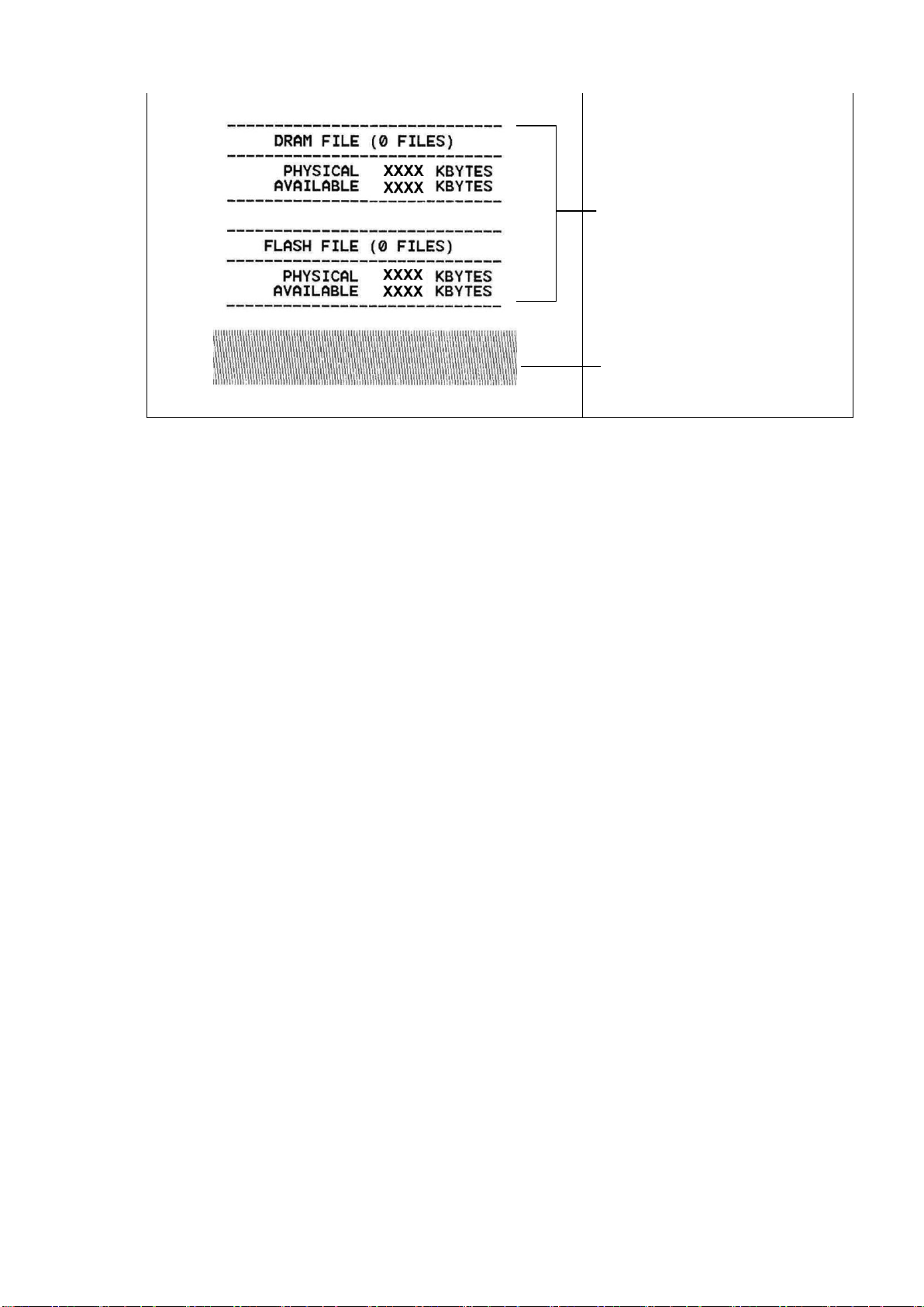
21
Numbers of download files
Total & available memory
space
Print head check pattern
When the self test is completed, the printer enters the dump mode. Please turn
the printer's power off and then on again to resume normal printing.
Note:
The physical flash memory on board is 4MB respectively. Due to system
firmware will occupy 1.5MB, so total available flash memory space for
downloads is 2.5MB bytes.
The DRAM on board is 8MB respectively. For DRAM, system and image
buffer will occupy it, so total available DRAM for downloads will be 256 K
bytes.
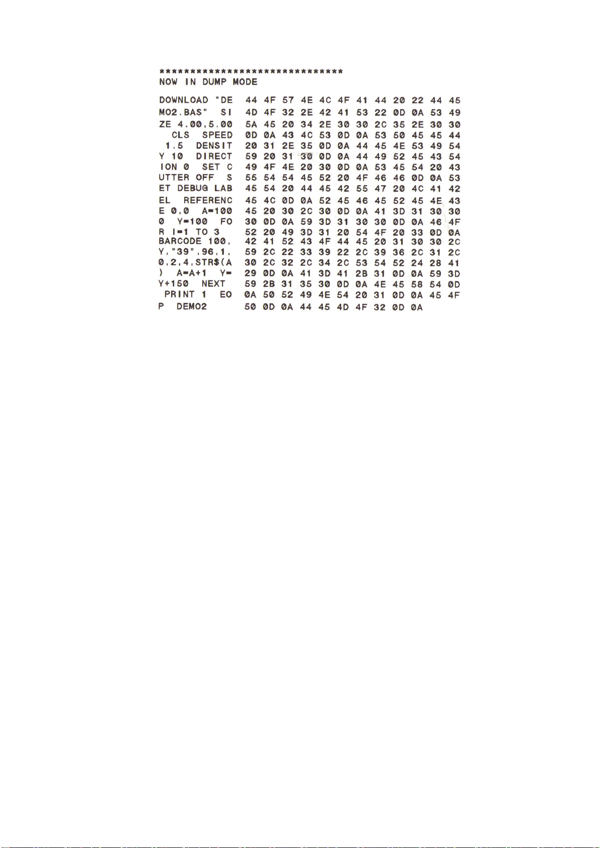
Dump Mode
After the self test, the printer enters the dump mode. In this mode, any characters sent from the host computer will be printed in two columns, as shown. The
characters received will be shown in the first column, and their corresponding
hexadecimal values, in the second. This is often helpful to users for the verification of programming commands or debugging of printer programs. Reset the
printer by turning the POWER switch off and on.
Page 25
22
4.2 Gap Sensor Calibration Utility
This utility is used to calibrate the sensitivity of the gap sensor. Users may have
to calibrate the gap sensor on two occasions:
1. Changing to a new type of label media.
2. Initializing the printer.
Note: The ERROR LED may flash if gap sensor is not calibrated properly.
Please follow the steps below to calibrate the gap sensor:
1. Turn off the printer power and install blank labels (without any logo or
character) on the printer.
2. Hold down the PAUSE button and turn on the printer power.
3. Release PAUSE button when the printer feeds labels. Do not turn off the
printer power until the printer stops and the two green LEDs light on.
Note: Black mark sensor has fixed sensitivity. It is no need to calibrate the
black mark sensor
Page 26
23
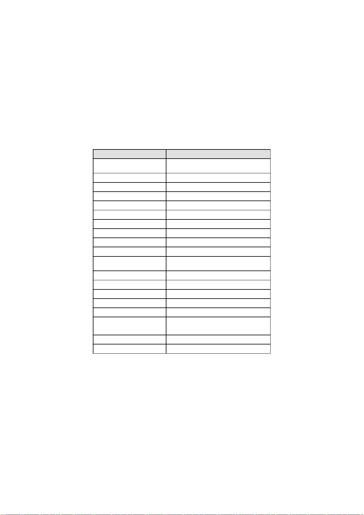
Parameter
Default setting
Speed
50.8 mm/sec(2 ips)(203DPI)
38.1 mm/sec(1.5 ips)(300DPI)
Density
8
Label width
4” (101.6 mm)
Label height
4” (101.6 mm)
Sensor type
Gap sensor
Gap setting
0.12” (3.0 mm)
Print direction
0
Reference point
0,0 (upper left corner)
Offset
0
Print mode
Tear Mode
Serial port settings
9600 bps, none parity, 8 data bits, 1
stop bit
Code page
850
Country code
001
Clear flash memory
Yes
Shift X
0
Shift Y
0
Gap sensor
sensitivity
8
LCD Language
ENGLISH
IP address
DHCP
4.3 Printer Initialization
Printer initialization clears all downloaded files resident in the flash memory and
sets printer parameters to default values.
Please follow the steps below to initialize the printer:
1. Turn off the printer power.
2. Hold down the PAUSE and FEED buttons and turn on the printer power.
3. Do not release the buttons until the three LEDs flash in turn.
Note:
Printing method (thermal transfer or thermal direct printing ) will be set
automatically at the activation of printer power.
Download files will be deleted after printer initialization.
Sensor calibration is required after printer initialization before printing
labels.
Page 27
24
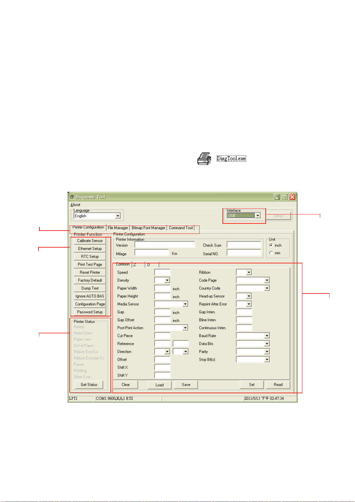
Features tab
Printer functions
Interface
Printer Status
Printer setup
5. DIAGNOSTIC TOOL
TSC’s Diagnostic Utility is an integrated tool incorporating features that enable
you to explore a printer’s settings/status; change a printer’s settings; download
graphics, fonts and firmware; create a printer bitmap font; and send additional
commands to a printer. With the aid of this powerful tool, you can review printer
status and settings in an instant, which makes it much easier to troubleshoot
problems and other issues.
5.1 Start the Diagnostic Tool
1. Double click on the Diagnostic tool icon to start the software.
2. There are four features (Printer Configuration, File Manager, Bitmap Font
Manager, Command Tool) included in the Diagnostic utility.
Page 28
25
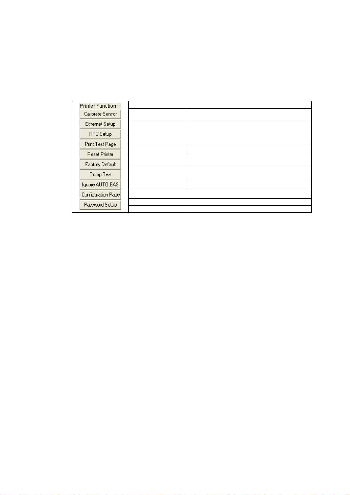
Function
Description
Calibrate Sensor
Calibrate the sensor specified in the Printer
Setup group media sensor field
Ethernet Setup
Setup the IP address, subnet mask, gateway
for the on board Ethernet
RTC Time
Synchronize printer Real Time Clock with PC
Print Test Page
Print a test page
Reset Printer
Reboot printer
Factory Default
Initialize the printer and restore the settings
to factory default.
Dump Text
To activate the printer dump mode.
Ignore AUTO.BAS
Ignore the downloaded AUTO.BAS program
Configuration Page
Print printer configuration
Password Setup
Set the password to protect the settings
5.2 Printer Function
1. Select the PC interface connected with bar code printer.
2. Click the “Function” button to setting.
3. The detail functions in the Printer Function Group are listed as below.
Note:
For more information about Diagnostic Tool, please refer to the diagnostic utility quick
start guide in the CD disk \ Utilities directory.
Page 29

26
Problem
Solution
Ribbon does not advance or
rewind
The media and ribbon must be installed
and close print head mechanism prior to
turning on printer power.
Poor print quality
Clean the thermal print head.
Adjust the print density setting.
Ribbon and media are not compatible.
Media thickness is over spec.
Power indicator does not
illuminate
Check the power cord, see whether it is
properly connected.
ON-LINE indicator is off, ERROR
indicator is on
Out of paper or out of ribbon
Calibrate the sensitivity of gap sensor.
Rewind ribbon paper core is not installed.
Continuous feeding when printing
labels
Calibrate the gap sensor.
6. TROUBLESHOOTING
The following guide lists some of the most common problems that may be
encountered when operating the bar code printer. If the printer still does not
function after all suggested solutions have been invoked, please contact the
Customer Service Department of your purchased reseller or distributor for
assistance
Page 30
27
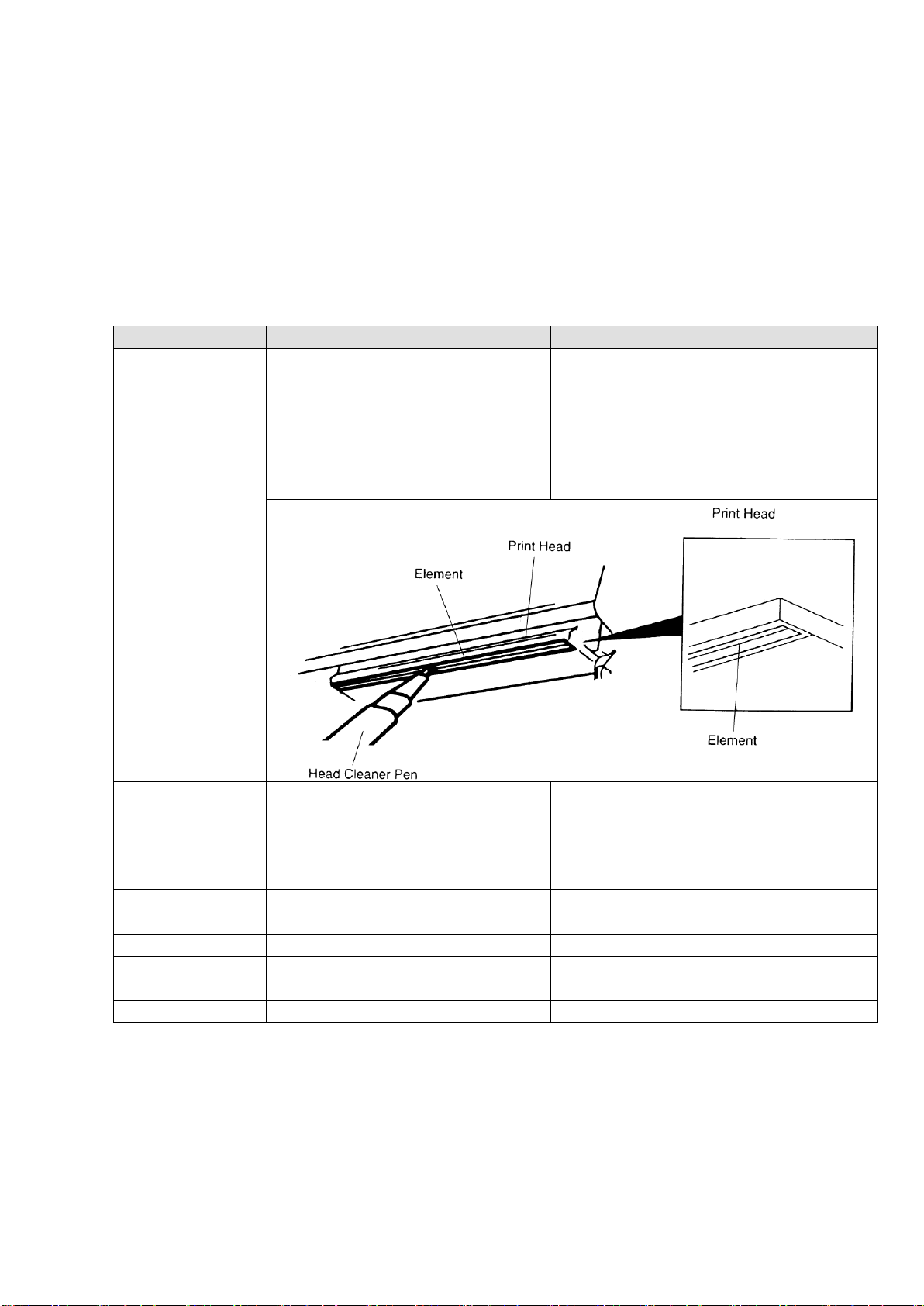
Printer Part
Method
Interval
Print Head
1. Always turn off the printer
before cleaning the print head.
2. Allow the print head to cool for
a minimum of one minute.
3. Use a cotton swab (Head
cleaner pen) and 100% ethanol
to clean the print head surface.
Clean the print head when changing a
new label roll
Platen Roller
1. Turn the power off.
2. Rotate the platen roller and
wipe it thoroughly with 100%
ethanol and a cotton swab, or
lint-free cloth.
Clean the platen roller when changing
a new label roll
Tear Bar/Peel
Bar
Use the lint-free cloth with 100%
ethanol to wipe it.
As needed
Sensor
Compressed air or vacuum
Monthly
Exterior
Wipe it with water-dampened
cloth
As needed
Interior
Brush or vacuum
As needed
7. MAINTENANCE
This session presents the clean tools and methods to maintain your printer.
1. Please use one of following material to clean the printer.
Cotton swab (Head cleaner pen)
Lint-free cloth
Vacuum / Blower brush
100% ethanol
2. The cleaning process is described as following,
Note:
Do not touch printer head by hand. If you touch it careless, please use ethanol
to clean it.
Please use 100% Ethenol. DO NOT use medical alcohol, which may damage
the printer head.
Regularly clean the print head and supply sensors once change a new ribbon to
keep printer performance and extend printer life.
Page 31

28
Date
Content
Editor
2013/3/21
Modify section 4.1
Camille
2013/4/3
Add cutter module specification on section 3.5
Add V7.0 F/W self test on section 4.1
Add TSC YouTube web address
Camille
Revise History
Page 32
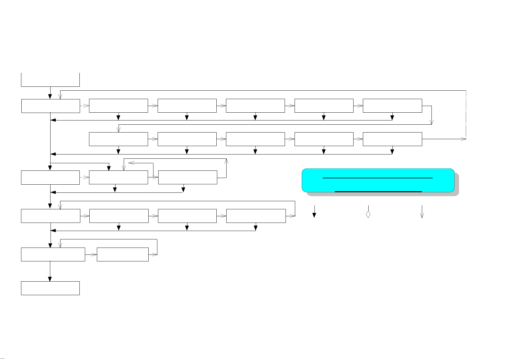
1
A-
PANEL CONTROL
FLOW CHART
MENU SELECT SET
PRINTER INFO.:
TTP243M V1.XX
FILE LIST:
END OF LIST
READY
FILE LIST:
XXXXXXXX.XXX
FILE LIST:
END OF LIST
PRINTER INFO.:
SPEED:3
PRINTER INFO.:
DENSITY:8
PRINTER INFO.:
COM1:96,N,8,1
PRINTER INFO.:
CODE PAGE:437
PRINTER INFO.:
COUNTRY:001
PRINTER INFO.:
SIZE:X.XX,X.XX
PRINTER INFO.:
GAP:X.XX,X.XX
PRINTER INFO.:
PEEL-OFF:OFF
PRINTER INFO.:
CUTTER:ON
PRINTER INFO.:
RIBBON:ON
MEMORY INFO.:
F-TOTAL: XXXX K
MEMORY INFO.:
F-AVAIL: XXXX K
DATE/TIME:
DATE:XXXX/XX/XX
PRINTER SETUP:
LANG:ENG
MEMORY INFO.:
D-AVAIL: XXXX K
MEMORY INFO.:
D-TOTAL: XXXX K
DATE/TIME:
TIME:XX:XX
Appendix A Menu Control Flowchart (Option)
The following shows the control flowchart of the menu.
(Continued on next page)
Page 33
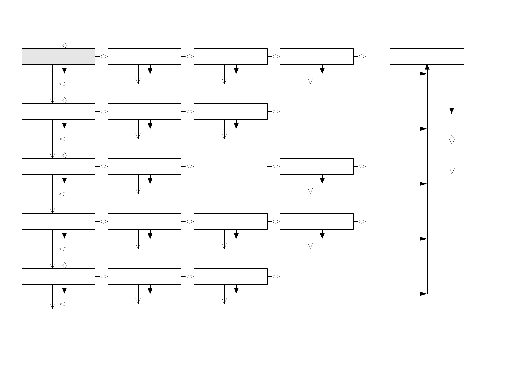
2
A-
PRINTER SETUP:
LANG:ENG
PRINTER SETUP:
SPEED:1.5
MENU
SELECT
SET
PRINTER SETUP:
LANG:
繁體中文
PRINTER SETUP:
LANG:
日本語
PRINTER SETUP:
LANG:
簡体中文
READY
PRINTER SETUP:
SPEED:2
PRINTER SETUP:
SPEED:3
PRINTER SETUP:
DENSITY:0
PRINTER SETUP:
DENSITY:1
PRINTER SETUP:
DENSITY:15
......
PRINTER SETUP:
BAUD RATE:19200
PRINTER SETUP:
BAUD RATE:9600
PRINTER SETUP:
BAUD RATE:2400
PRINTER SETUP:
BAUD RATE:4800
PRINTER SETUP:
PARITY:NONE
PRINTER SETUP:
PARITY:EVEN
PRINTER SETUP:
PARITY:ODD
PRINTER SETUP:
DATA BITS:8
(Continued on next page)
Page 34
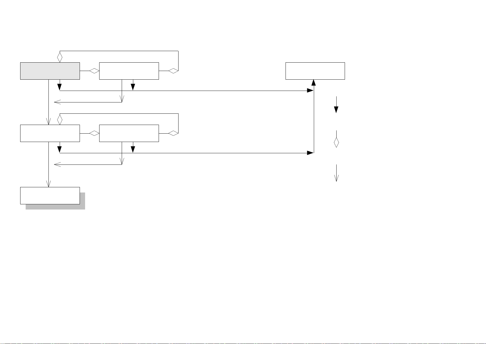
3
A-
PRINTER SETUP:
DATA BITS:8
PRINTER SETUP:
DATA BITS:7
PRINTER SETUP:
STOP BITS:1
PRINTER SETUP:
STOP BITS:2
READY
PRINTER SETUP:
LANG:ENG
MENU
SELECT
SET
Page 35

Corporate Headquarters Li Ze Plant
9F., No.95, Minquan Rd., Xindian Dist., No.35, Sec. 2, Ligong 1st Rd., Wujie Township,
New Taipei City 23141, Taiwan (R.O.C.) Yilan County 26841, Taiwan (R.O.C.)
TEL: +886-2-2218-6789 TEL: +886-3-990-6677
FAX: +886-2-2218-5678 FAX: +886-3-990-5577
Web site: www.tscprinters.com
E-mail: [email protected]
TSC Auto ID Technology Co., Ltd.
 Loading...