

Page 1

CPX4D / CPX4P Series
COLOR INKJET LABEL PRINTER
Installation Procedure
Printed in Japan
Page 2

Page 3

Installation
How to Utilize this Installation ............................................................................................... 1
Symbols in the Illustration ................................................................................................................... 1
Checking before Installation .................................................................................................. 2
Checking the Power Supply ................................................................................................................. 2
Checking the Installation Environment ................................................................................................ 2
Checking the Installation Space ........................................................................................................... 3
Installation Precautions ......................................................................................................... 4
Checking the Contents ........................................................................................................... 5
Unpacking Procedure ............................................................................................................. 6
Installation Procedure ............................................................................................................ 8
Mounting Printhead Unit ..................................................................................................................... 8
Loading Ink Tanks ............................................................................................................................... 13
Installing Cutter Unit .......................................................................................................................... 14
Initial Ink Loading ............................................................................................................................... 15
Checking after Installation ................................................................................................... 16
Setting of Test Label........................................................................................................................... 16
Printing and Checking a Nozzle Check Pattern .................................................................................. 17
Cleaning Procedure of Printhead Face ............................................................................................... 20
Confirmation of Printhead Position ................................................................................................... 22
Page 4

How to Utilize this Installation
Screw
Packaged Item
Unused Parts
Install
Remove
Tighten
Loosen
Harness
(Common for Guides and Clamps)
Connector
Power Cord
Install
Remove
Connect
Disconnect
Disconnect
Connect
Power
Check the
sound
Check
visually
Symbols in the Illustration
The frequently-performed operations are described with symbols in this procedure.
ON OFF
Check Push Cleaning
1
Page 5

Checking before Installation
Following shows requirements for the installation site. Therefore, it is desirable to see the installation site in
advance before bringing in this Printer to the user's site.
Checking the Power Supply
1. Printer must be connectable to the outlet that can supply the rated voltage +10/-15% at the
specified ampere or higher.
2. Install this Printer near the power outlet and leave sufficient space around the power plug so that it
can be unplugged easily in an emergency.
Checking the Installation Environment
1. The installation environment must be as described below. Avoid installing Printer near the faucet,
water heater, humidifier, or refrigerator.
Operating temperature range: 15 to 30 degrees Celsius
Operating humidity range: 10%RH to 80%RH
2. Avoid placing Printer in place exposed to high temperature and humidity, extremely low
temperature, severe temperature changes, and direct sunlight. Especially, avoid placing Printer near
fire, out of doors, in distribution warehouse, or in refrigerator.
3. Avoid installing Printer in an area subject to dust.
4. The room must be well-ventilated properly.
5. None of Printer feet should float. The machine must be held level constantly.
6. When placing Printer on desk, table or the like, it must be sturdy and stable enough to support
weight of Printer.
2
Page 6

Checking the Installation Space
The minimum space required for installation is shown below.
3
Page 7

Installation Precautions
When installing Printer, observe the following precautions.
• Imaging faults can result due to dew condensation that occurs when the machine is moved from a cold
place to a warm place. Leave the machine kept packed for at least 2 hours before installing it.
(Dew condensation: When a metallic object is brought from a low-temperature place to a
high-temperature place, water vapor around it is cooled abruptly and consequently water drops stick to
the surface of the metallic object.)
• Printer weighs about 24 kg. At least two persons are required to install it. In addition, be sure to keep
the machine leveled when lifting it.
• Be sure to wear a grounding wrist strap prior to the service work to prevent electrostatic destruction of the
printheads, PCB's, etc.
4
Page 8

Checking the Contents
<Others>
• Including guides
• Printer Software CD-ROM
CAUTION:
Several types of Power Cords come with Printer. Use appropriate Power Cord for the power supply used at the
installation site.
5
Page 9
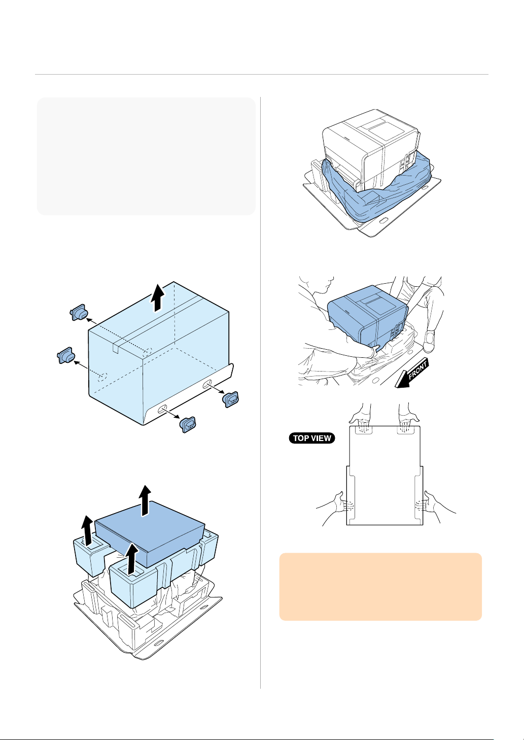
Unpacking Procedure
3. Strip the plastic bag from top to bottom.
relocation or repair of Printer.
Do not hold the front side of Printer.
NOTE:
Printer is secured using shipping tapes and
cushioning materials to protect it against the
vibrations and shocks applied during transportation.
By following the procedure described below, remove
all pieces of shipping tapes and cushioning materials
before installing Printer. Keep the removed
cushioning materials for future transportation for
1. Remove 4 grips from the packing carton, and
then remove the outer casing.
4. Holding the handles at the bottom of Printer,
lift Printer to take it out from the package
base.
B
A
2. Remove Accessory Box, and then remove
Upper Pads.
B
A
CAUTION:
Printer weights about 24 kg. At least, two
persons are required to lift it up.
5. Place Printer on a horizontal table, and then
remove all pieces of shipping tape and
cushioning materials visible on the exterior of
Print e r.
6
Page 10
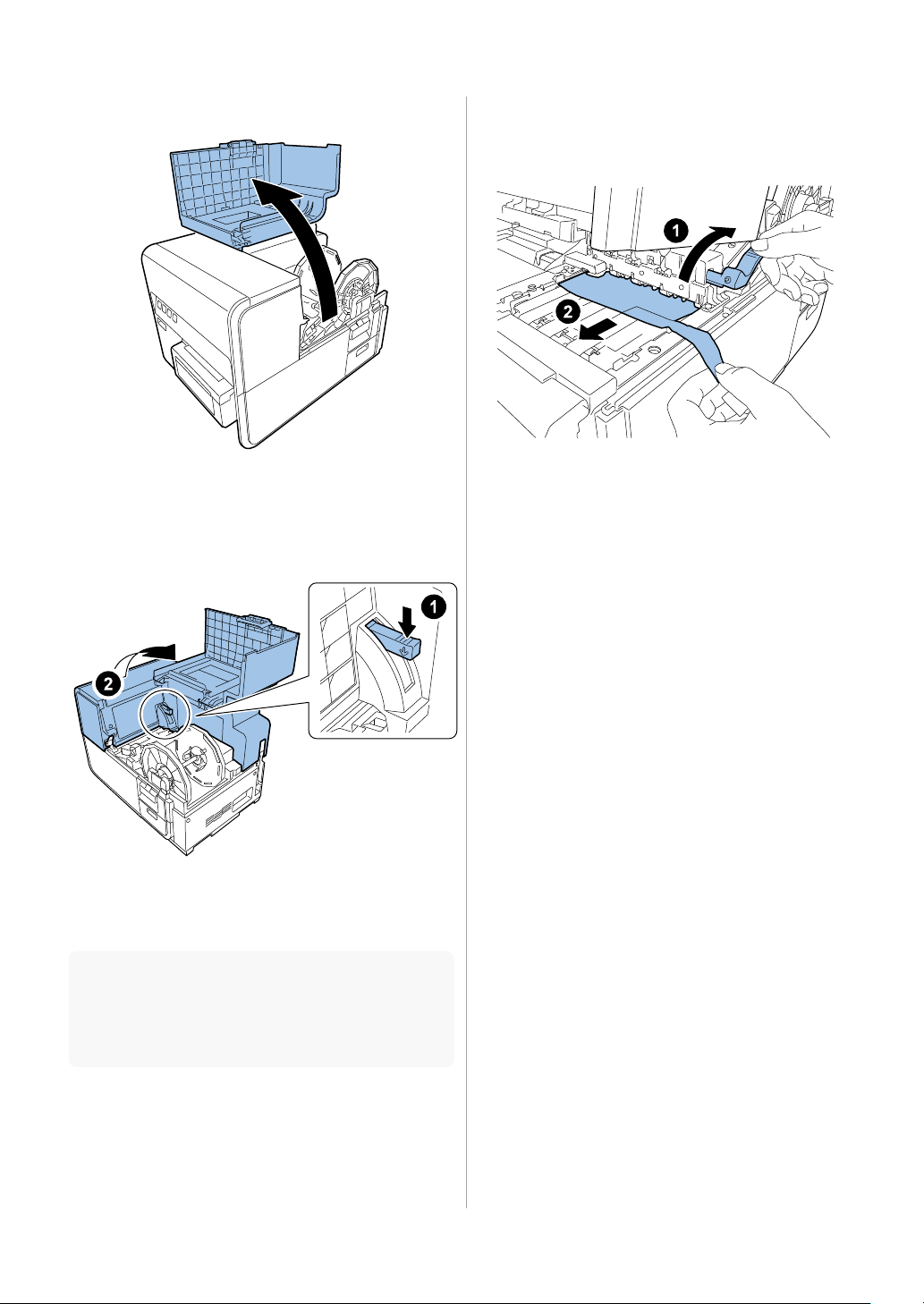
6. Open Roll Cover.
10. Turn Pinch Roller Release Lever, and then
Printer, etc.
7. Remove all pieces of the tape securing Roll
Holder.
8. Push down Upper Unit Open Lever, and then
open Upper Unit.
remove the protection sheet.
9. Remove shipping tapes and cushioning
materials from inside of Printer.
NOTE:
Save and store the removed cushioning materials for
future transportation in relocation, repairing of
7
Page 11
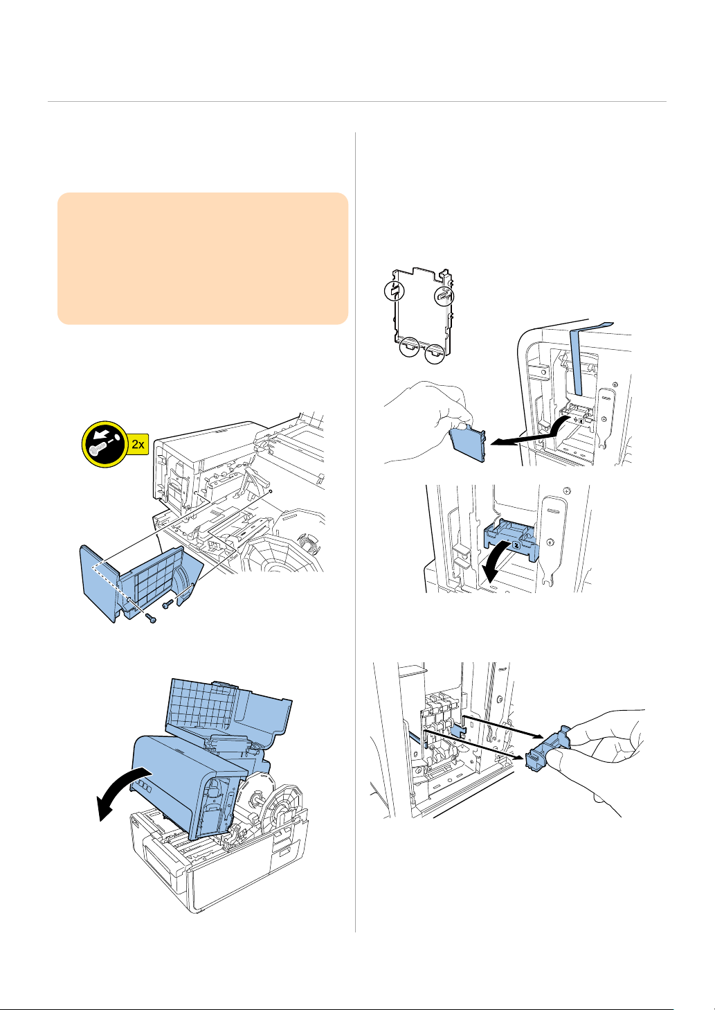
Installation Procedure
the handling.
Mounting Printhead Unit
CAUTION:
Semiconductive components are used in the
printhead.
As careless handling of the printhead under low
humidity may cause electrostatic destruction in it,
be sure to wear a grounding wrist strap prior to
1. Remove 2 screws to remove Maintenance
Cover from Upper Unit.
2 screws
3. Remove the shipping tape, remove Print
Module Cover, and then open Lower
Printhead Release Lever.
2. Close Upper Unit.
4. Remove Blade Cleaner.
8
Page 12
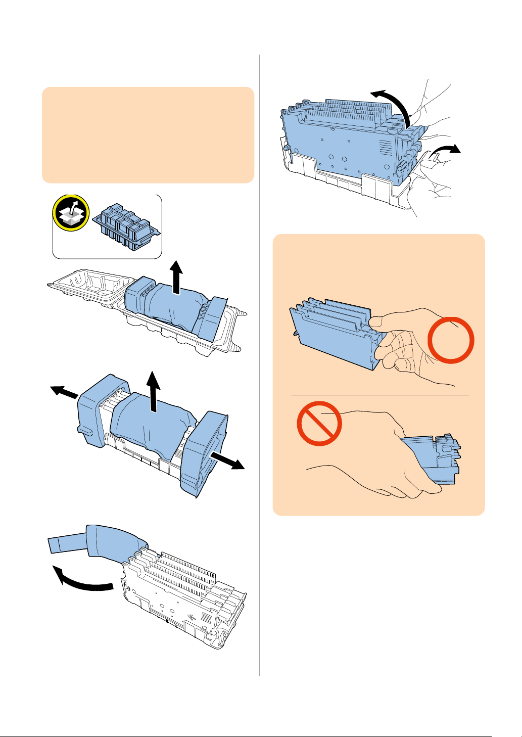
5. Take out included Printhead from the
8. Take Printhead Unit out of the case.
the handling.
package.
CAUTION:
Semiconductive components are used in the
printhead.
As careless handling of the printhead under low
humidity may cause electrostatic destruction in it,
be sure to wear a grounding wrist strap prior to
6. Remove the cover and cushioning materials.
CAUTION:
Do not touch the circuit boards and Printhead
face. An ink injection problem can occur.
7. Remove the protection.
9
Page 13
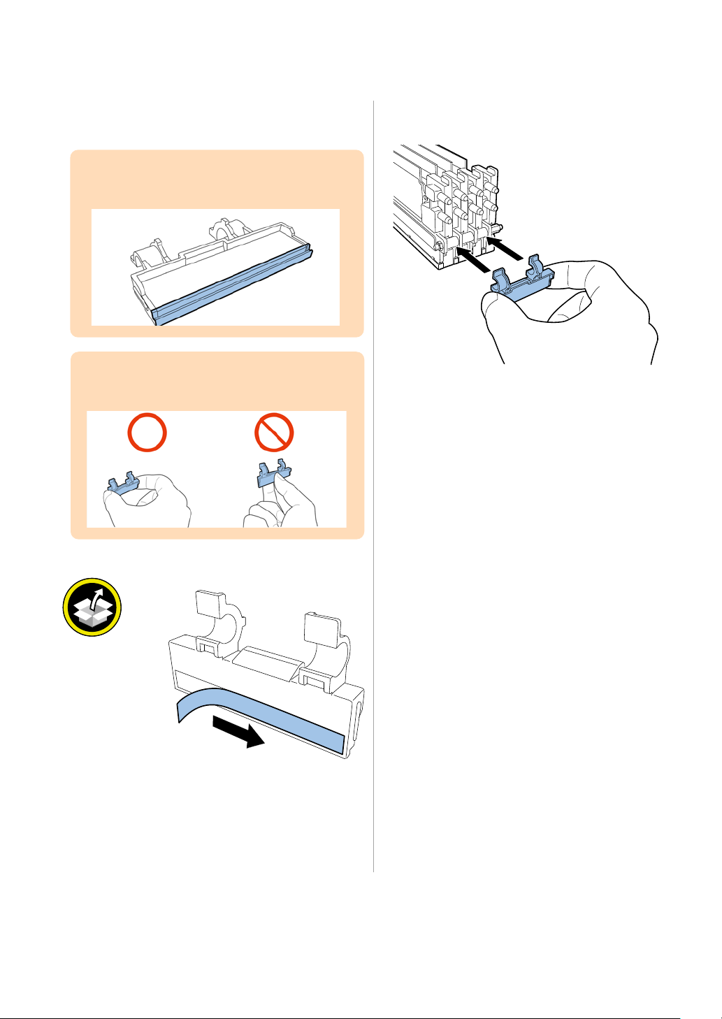
For CPX4P model ONLY [For CPX4D model, please go to next page (Step 11) to install the Printhead Unit.]
9. For C PX4P, peel the release paper from bundled
10. For C PX 4 P, attach Scraper to Printhead.
Scra p e r.
CAUTION:
Do not touch the area indicated in the following
figure.
CAUTION:
Handle scraper as following figure.
10
Page 14
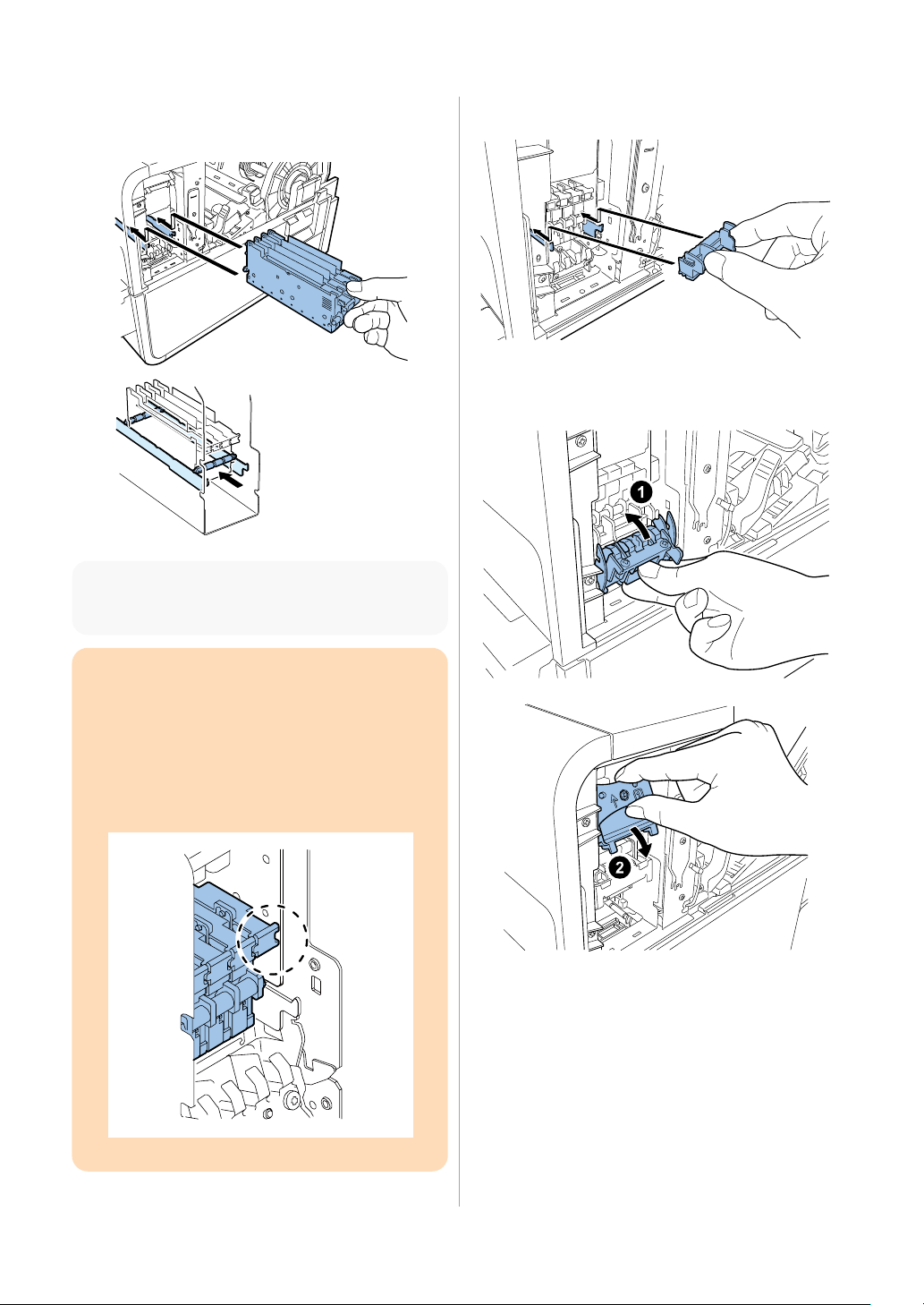
11. Put Printhead Unit on the rail guide, and then
12. Mount Blade Cleaner.
Skewering Shaft must be on Printhead Guide Rails.
insert it into Printer until it stops.
NOTE:
CAUTION:
To confirm Printhead Unit is in the correct
position, see if the end of Printhead Unit grip
and the edge of the inner metal plate are in the
same plane as shown in the figure.
If Printhead Unit is insufficiently inserted, Lower
Printhead Release Lever cannot be closed.
13. Close Lower Printhead Release Lever and
Upper Printhead Release Lever.
11
Page 15

14. Check that numbers [1] , [2], and [3]
15. Attach Print Module Cover to Print Module.
mounted. Follow the steps 11 and 11 again.
apertures.
indicated on Print Module are visible.
NOTE:
If any one of numbers [1] , [2], and [3] is invisible,
Printhead Release Lever ( [1] ,[2] ) has not been
closed or Blade Cleaner ( [3] ) has not been
CAUTION:
After removing the shipping tapes, Upper/Lower
Printhead Release Levers could slightly be opened
and therefore confirm these levers are firmly
closed as shown in the figure.
CAUTION:
Set Print Module Cover surely.
Confirm that claws are in the rectangular
16. Push down Upper Unit Open Lever, and then
open Upper Unit.
12
Page 16
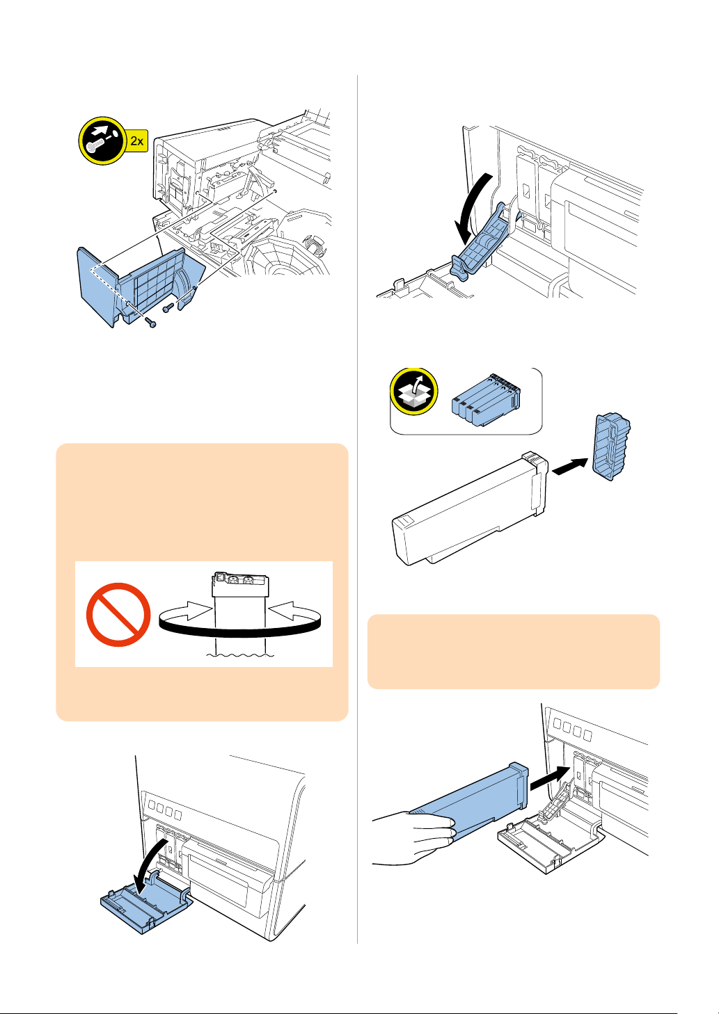
17. Mount Maintenance Cover on Upper Unit.
2. Open Ink Tank Lever for each color while
from Printer and reinstall it.
in a wrong Ink Tank Slot.
18. Close Upper Unit, and then close Roll Cover.
Loading Ink Tanks
CAUTION:
Do not shake the Ink Tank (Dye Ink/ For CPX4D).
Shaking Ink Tank makes bubbles in Ink Tank. The
bubbles cause misdetection of ink remaining, and
operator call error (XXXX Ink Empty/error code:
20XX) might be occur.
In the case shaking Ink Tank by mistake, remove it
1. Open Ink Tank Door.
pushing it downward.
3. Take out included Ink Tanks from the packages,
and then remove the cushioning materials.
4. Slowly insert Ink Ta n k as far as it will go.
CAUTION:
Ink Tank cannot be loaded properly if it is inserted
13
Page 17
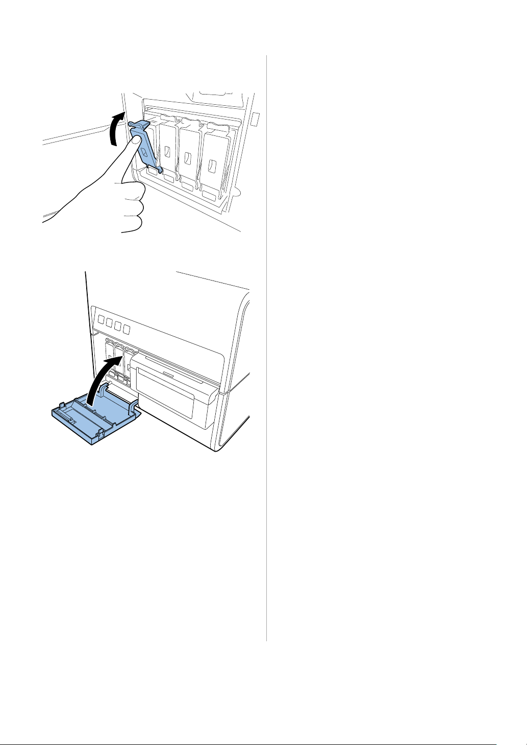
5. Close Ink Tank Lever.
6. Set the rest of Ink Tanks and close Ink Tank Door.
Installing Cutter Unit
In the case installing Optional Cutter Unit, follow
the installation procedure of Optional Cutter Unit.
14
Page 18
goes back to lighting and a buzzer sounds.
Initial Ink Loading
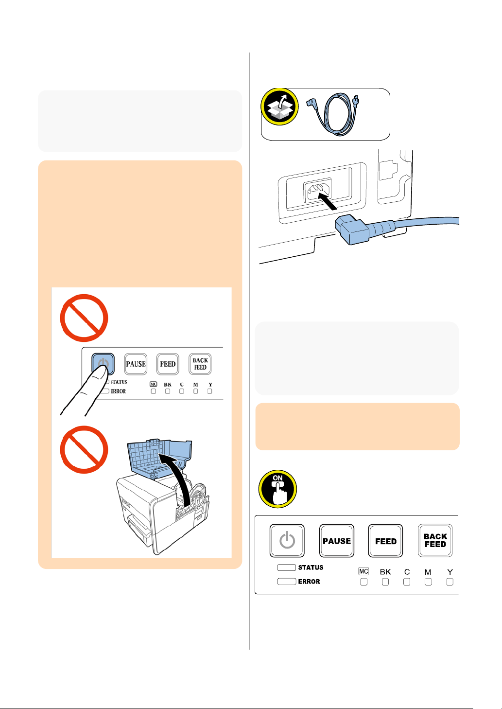
Note:
Initial ink loading takes about 25 minutes.
Ink loading time might be changed due to the
design change.
CAUTION:
Do not turn the power OFF or open covers and
doors such as Roll Cover during ink loading.
Should Power key be switched OFF or covers be
opened during ink loading, its operation will be
terminated and has to be started from the
beginning. In such a case, turn on the power to
start ink loading again.
Restarting the ink loading results in more ink
consumption.
1. Connect Power Cord to Printer.
2. Connect Power Cord to the outlet.
3. Press Power key to turn the main power ON.
Note:
When [STATUS] Lamp changes from lighting to
flashing, initial ink loading starts automatically.
When the ink loading has completed, the lamp
CAUTION:
Ensure that [STATUS] Lamp went lighting before
moving to the next step.
15
Page 19
Checking after Installation
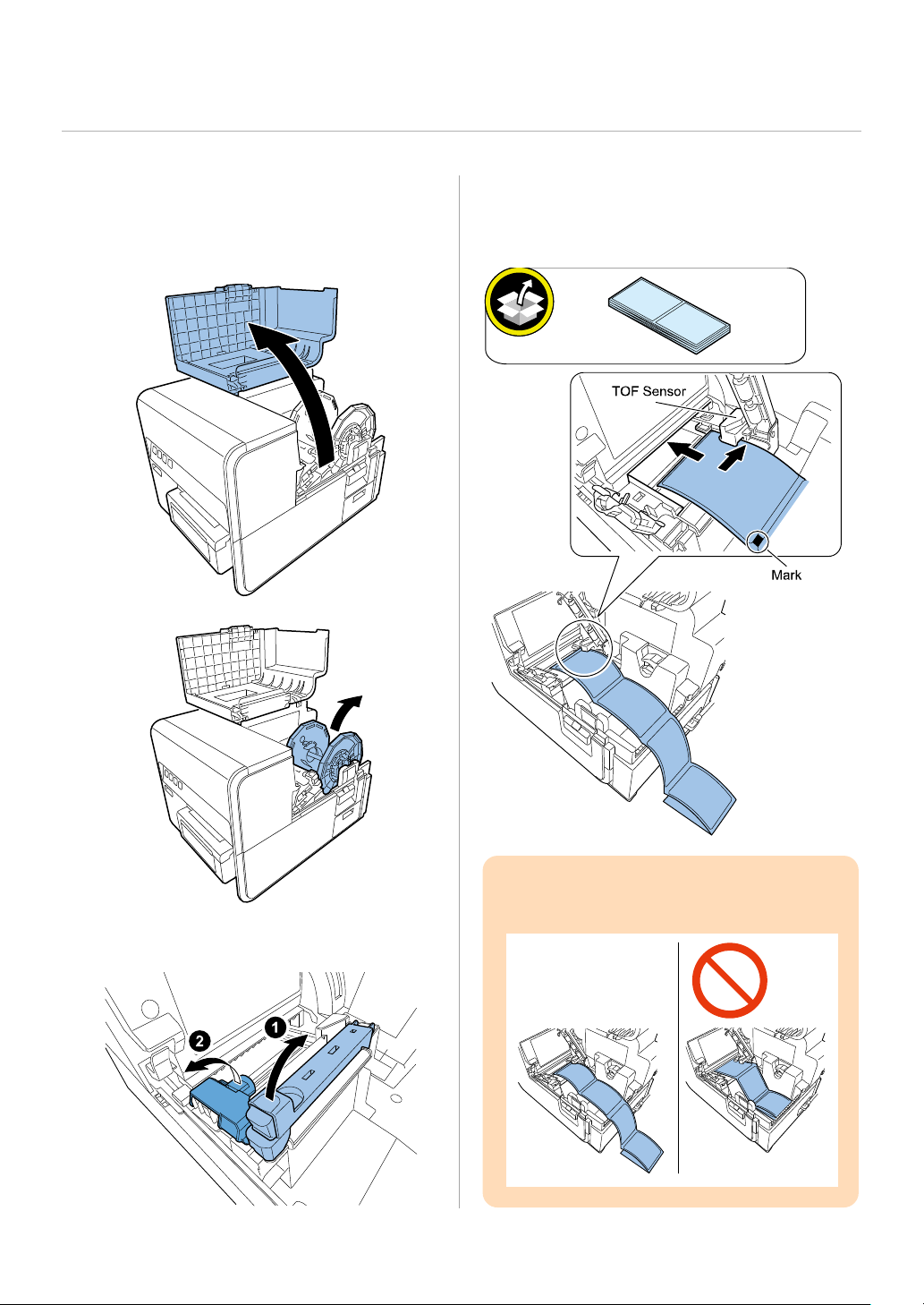
3. Insert Test Label along the left-side guide
Setting of Test Label
1. Open Roll Cover and take out Roll Holder.
under TOF Sensor until it stops at the roller in
the feeder slot.
2. Open Paper Guide and Transport Guide.
Attention:
16
Do not put Test Label inside Printer.
Page 20
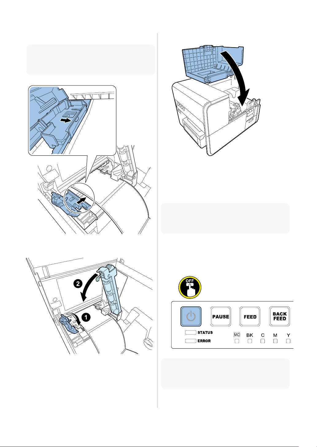
4. Slide and align Transport Guide with the paper.
6. Close Roll Cover.
a paper jam.
Utility.
to shutdown Printer.
Note:
Do not give too much stress on the paper to avoid
5. Slowly close Transport Guide and Paper Guide.
Printing and Checking a
Nozzle Check Pattern
Note:
Nozzle Check Pattern can be printed using Service
1. Shutdown Printer as follows:
* Press and hold Power key down.
* Release Power key after a sound of the beep.
Note:
It takes approx. 30 sec. for the power off sequence
17
Page 21
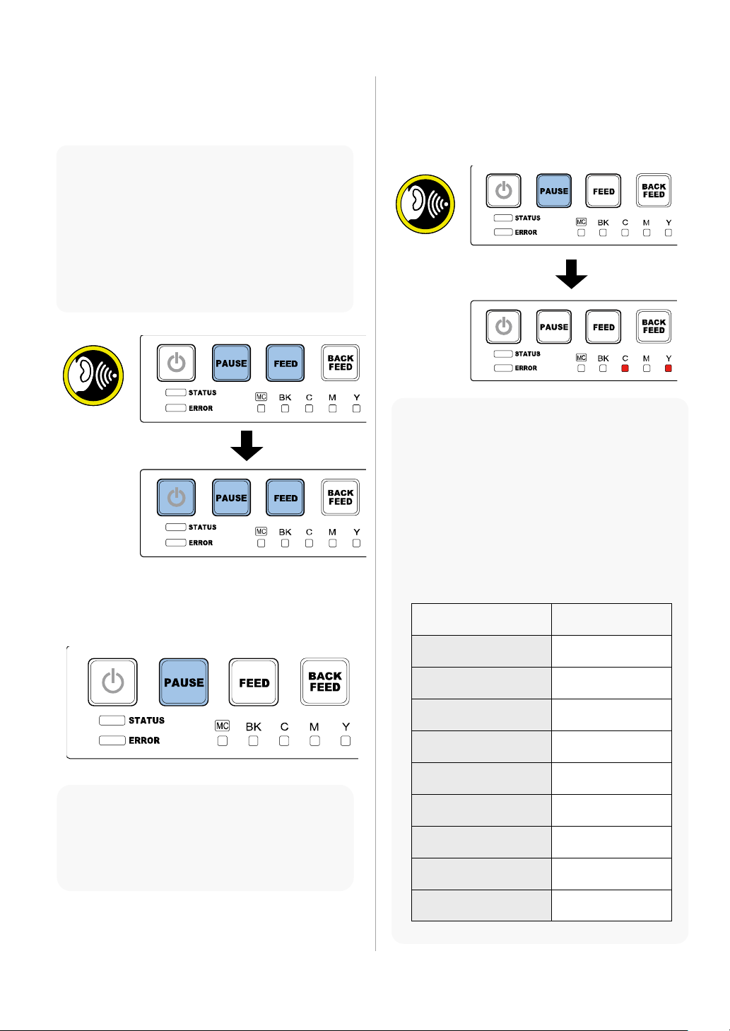
2. Press Power key while holding [PAUSE] and
4. Hold [PAUSE] Key down again. Release [PAUSE]
shutdown and try again.
flash.
[PAUSE] Key release
timing
Function to execute
Buzzer sounds once
(1 second later)
Strong cleaning
Buzzer sounds twice
(2 seconds later)
Initial ink loading
Buzzer sounds 3 times
(3 seconds later)
Shipping the printer
Buzzer sounds 4 times
(4 seconds later)
Printhead
replacement
Buzzer sounds 5 times
(5 seconds later)
Nozzle check
pattern printing
Buzzer sounds 6 times
(6 seconds later)
Setting value
printing
Buzzer sounds 7 times
(7 seconds later)
Printhead moving
to print position
Buzzer sounds 8 times
(8 seconds later)
Not to execute
9 seconds or more later
(no buzzer)
Not to execute (no
buzzer)
[FEED] Keys ON at a time. Release all keys when
the second buzzer sounds.
Note:
Keep pressing 3 keys down until the second
buzzer sounds.
<Timing when the buzzer sounds>
1st time: Immediately after pressing 3 Keys.
2nd time: 7 seconds after the first
Check that power lamp is repeating 3-time
3. Press [PAUSE ] Key once to enter Maintenance
Mode.
Key when the buzzer sounds 5 times. After
releasing [PAUSE] Key, confirm Ink Warning
Lamps of cyan (C) and yellow (Y) are lit.
Note:
Buzzer beeps every 1 sec. When [PAUSE] Key is
holding pressed at Maintenance Mode.
If a wrong function has mistakenly been
selected, try again to select the Nozzle Check
Pattern Printing by simply pressing [PAUSE] Key
down and wait for 5 buzzer sounds.
When Printer is left untouched for 15 sec. or
more after selecting the function, the current
selection is canceled and the function should be
selected again with [PAUSE] Key.
<Table 1>
Note:
When Printer enters Maintenance Mode, power
lamp is repeating 4-time flash. If power lamp is lit,
hold Power key for 1 second or longer to
18
Page 22

5. Press [PAUSE] Key once. A Nozzle Check Pattern
7. Observe printed Nozzle Check Pattern. In the
to "Cleaning Procedure of Printhead Face."
to shutdown Printer.
is printed.
Note:
To cancel the operation after executing some
function, press Power key for 1 sec. or more to
shutdown.
If "Shipping the printer" or "Printhead
replacement" is mistakenly executed, ink
drainage is executed. In such the cases, turn off
the power and enter Maintenance Mode again.
Then load ink manually and execute Nozzle
Check Pattern printing.
6. When the Optional Cutter Unit is not installed,
open Cutter Cover and slide the cutter to cut the
paper.
case that white streak is in solid printed area,
execute strong cleaning once. Refer to the
table 1 in step 4.
Note:
Strong cleaning takes approx. 8 min.
In the case that the white streak is only in the
hatched area, not in the solid printed area,
strong cleaning is not required.
Strong cleaning can also be executed using
Service Utility.
When Optional Cutter Unit is installed, the paper
is automatically cut.
8. Confirm that the white streak has been
eliminated.
Note:
If there is still white streak remaining after the
strong cleaning, clean the printhead face referring
9. Shutdown Printer as follows:
* Press and hold Power key down.
* Release Power key after a sound of the beep.
Note:
It takes approx. 30 sec. for the power off sequence
19
Page 23
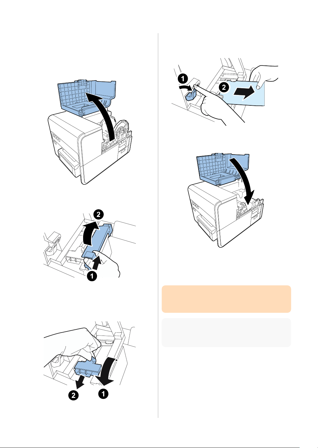
Cleaning Procedure of
4. While pressing Jam Release Lever down, pull
time.
print position.
Printhead Face
1. Open Roll Cover.
2. Open Paper Guide.
out paper.
5. Close Roll Cover.
3. Open Transport Guide and slide it in the arrow
direction.
6. Refer to the table 1 in step 4 of "Printing and
Checking a Nozzle Check Pattern" to move
Printhead to the print position.
CAUTION:
Do not keep Printhead at print position for a long
Note:
It takes approx. 5 sec. that Printhead comes to the
7. Open Upper Unit.
20
Page 24
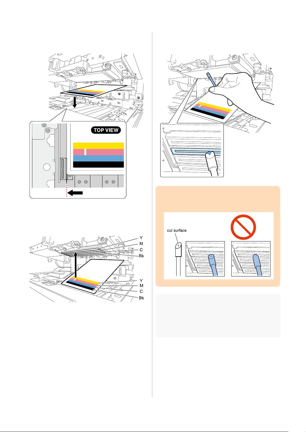
8. Place the Nozzle Check Pattern as shown in the
10. Put the cleaning stick on the nozzles for
figure.
9. Identify the position of non-discharging
nozzle(s) depending on the corresponding
position of the white streak(s).
approx. 5 sec. to have it soaked with ink.
CAUTION:
Do not have the cut surface contact the Printhead
face.
Note:
1 Cleaning Stick covers all the 4 colors of Printhead
for the cleaning. Cleaning Printheads for different
colors with the same Cleaning Stick does not affect
the quality of printed colors.
21
Page 25
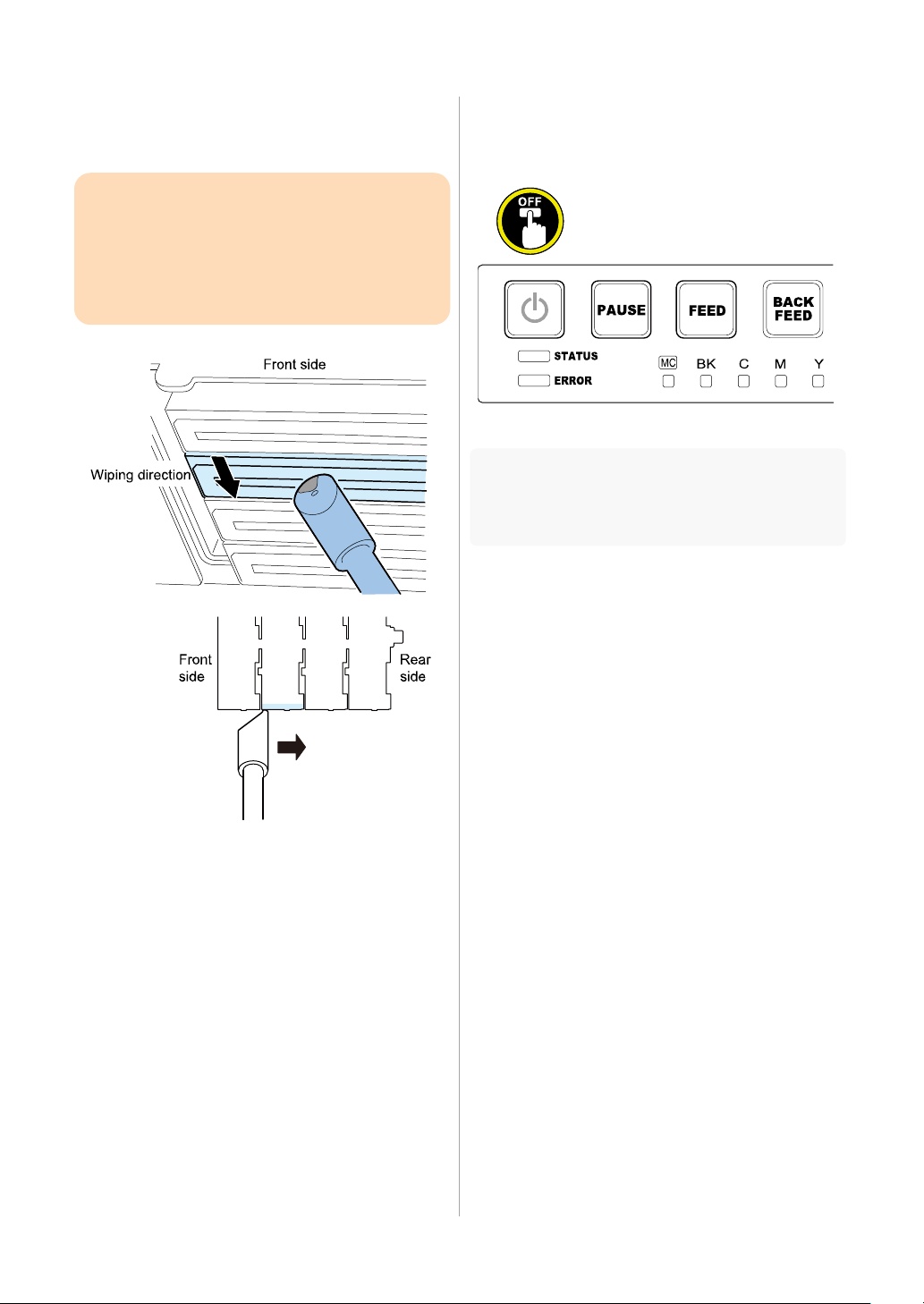
11. Confirm that ink is absorbed in the tip of
14. Shutdown Printer as follows:
damage may result on it.
Cleaning Stick. Then wipe off Printhead surface
from front to rear several times.
CAUTION:
Do not wipe the face of Printhead too hard.
Wiping the surface too hard may cause damage
on the printhead.
Never touch the Printhead surface. Fatal
* Press and hold Power key down.
* Release Power key after a sound of the beep.
Note:
It may take 30 sec. or more for shutdown sequence
after releasing the Power key.
12. Remove Nozzle Check Pattern.
13. Close Upper Unit and print the Nozzle Check
Pattern again to check if the white streak is
eliminated.
Confirmation of Printhead
Position
Confirm that the relative mis-registrations among
different colors are not observed in printed
image. If there should be the mis-registration,
adjust Printhead positions via Service Utility or
Printer Driver.
22
Page 26

TSC Auto ID Technology America Inc.
TSC Auto ID Technology EMEA GmbH
TSC Auto ID Technology Co., Ltd.
Corpo rate Headquarters
9F., No.95, Minquan Rd., X indian Dist.,
Ne w Ta ipei City 23141 , Taiwan ( R.O.C.)
TEL: +886-2-2218-6789
FAX: +886-2-2218-5678
Web site: www.tscprinters.com
E-mail: printer_sales @tscprinters.com
3040 Saturn Street Suite # 200
Brea, CA 92821 (U.S.A.)
TEL: +1 657 258 08 08
Technical Support TEL: +1 657 220 7995
FAX: +1 657 258 0809
E-mail: [email protected]
Georg -Wimmer-Ring 8b
85604 Zorneding (Germany)
TEL: +49 (0) 8106 3 7979 00
FAX: +49 (0) 8106 37979 05
Web site: www.tscprinters.com
E-mail: [email protected]
 Loading...