

Page 1

TTP-244ME Plus / 342M Plus
THERMAL TRANSFER / DIRECT THERMAL
BAR CODE PRINTER
USER’S
MANUAL
Page 2

CONTENTS
1. PRODUCT INTRODUCTION..........................................................1
1.1 Compliances..................................................................................................... 1
2. GETTING STARTED ......................................................................3
2.1 Unpacking and Inspection............................................................................ 3
2.2 Equipment Checklist..................................................................................... 3
2.3 Printer Parts................................................................................................. 4
2.4 Buttons and Indicators.................................................................................. 7
3. SET UP...........................................................................................9
3.1 Setting Up the Printer................................................................................... 9
3.2 Loading Label Stock..................................................................................... 9
3.3 Self-Peeling Function................................................................................. 12
3.4 Cutter Function........................................................................................... 14
3.5 Ribbon Loading Instructions....................................................................... 15
3.6 Self Test..................................................................................................... 18
3.7 Dump Mode................................................................................................ 20
4. USING THE PRINTER..................................................................21
4.1 Power-on Utilities ....................................................................................... 21
4.1.1 Self Test Utility.................................................................................... 21
4.1.2 Gap Sensor Calibration Utility............................................................. 21
4.1.3 Printer Initialization.............................................................................. 22
4.2 Troubleshooting Guide............................................................................... 23
APPENDIX A MENU CONTROL FLOWCHART....................................1
i
Page 3

1. PRODUCT INTRODUCTION
Thank you very much for purchasing this bar code printer. The attractive printer
delivers superior performance at an economical price. Both powerful and easy-touse, this printer is your best choice.
The printer offers both thermal transfer and direct thermal printing at user
selectable speeds: either 1.5, 2.0, 3.0 and 4.0 IPS (Inch Per Second) for 203 DPI
model; 1.0, 1.5 and 2.0 IPS for 300 DPI model. It can accept a wide range of
media, including roll feed, die-cut, and fan-fold labels for both thermal transfer
and direct thermal printing. All of the most frequently used bar code formats are
available. Fonts and bar codes can be printed in any one of the four directions.
This printer provides a choice of five different sizes of alphanumeric fonts. By
using font multiplication, an even greater range of sizes is possible. Smooth fonts
can be down-loaded from the user friendly, Windows labeling software. In
addition, this printer is capable of independently executing BASIC programming
functions, including arithmetic, logical operation, loop, flow-control and file
management, among others. This programming capability provides the greatest
efficiency in label printing. The status of printer and error messages can be
displayed on the LCD screen. Unlike its predecessors, this model features an
LCD screen to facilitate the operation of the printer. This new feature enables the
user to view printer status or set printing parameters directly on the printer unit in
English, Chinese, Japanese, Italian…etc., making interfacing with the printer all
the more simple and viable!
1.1 Compliances
CE:
EN55022:1998+A1: 2000+A2: 2003, Class A
EN55024: 1998+A1: 2001+A2: 2003 IEC 61000-4 Series
EN61000-3-2: 2000 & EN61000-3-3: 1995+A1: 2001
UL/CUL:
UL1950, File Number: 178707
1
Page 4

FCC Class A
This equipment has been tested and found to comply with the limits for a Class A
digital device, pursuant to Part 15 of the FCC Rules. These limits are designed
to provide reason-able protection against harmful interference when the
equipment is operated in a commercial environment. This equipment generates,
uses and can radiate radio frequency energy, and if not installed and used in
accordance with the instruction manual, may cause harmful interference to radio
communications. Operation of this equipment in a residential area is likely to
cause harmful interference in which the user will be required to correct the
interference at his or her own expense.
TUV/ Safety:
EN60950, Certificate Number: AL990636129001
Wichtige Sicherheits-Hinweise
1. Bitte lesen Sie Diese Hinweis sorgfältig durch
2. Heben Sie diese Anleitung fűr den späteren Gebrauch auf.
3. Vor jedem Reinigen ist das Gerät vom Stromentz zu trennen. Verwenden Sie
Keine Flűssig-oder Aerosolreiniger. Am besten eignet sich ein angefeuchtetes
Tuch zur Reinigung.
4. Die Netzanschlußsteckdose soll nahe dem Gerät angebraucht und leicht
zugänglich sein.
5. Das Gerät ist vor Feuchtigkeit zu schűtzen.
6. Bei der Aufstellung des Gerätes ist auf sicheren Stand zu achten. Ein Kippen
oder Fallen könnte Beschädigungen hervorrufen.
7. Beáchten Sie beim Anschluß an das stromnetz die Anschlußwerte.
8. Dieses das Gerät kann bis zu einer Außentemperatur von maximal 40℃
betieben werden.
CAUTION
1. HAZARDOUS MOVING PARTS IN CUTTER MODULE. KEEP FINGER AND OTHER
BODY PARTS AWAY.
2. THE MAIN BOARD INCLUDES REAL TIME CLOCK FEATURE HAS LITHIUM BATTERY
CR2032 INSTALLED. RISK OF EXPLOSION IF BATTERY IS REPLACED BY AN
INCORRECT TYPE.
3. DISPOSE OF USED BATTERIES ACCORDING TO THE MANUFACTURER
INSTRUCTIONS.
2
Page 5

2. GETTING STARTED
2.1 Unpacking and Inspection
This printer has been specially packaged to withstand damage in the shipping
process. However, for fear that unexpected damage might occur, upon receiving
the bar code printer, carefully inspect the package and the device. In case of
evident damage, contact the carrier directly to specify the nature and extent of
the damage. Please retain the packaging materials in case you need to reship
the printer.
2.2 Equipment Checklist
z Bar code printer unit
z Ribbon paper core
z Ribbon supply/rewind spindle (2 pcs.)
z Centronics port cable
z Power cord
z Software/Windows driver CD disk
z Quick start guide
Separately purchased items may also be included. These additional items may
include:
z Labels
z Ribbons
z Memory module
z Cutter module
z Stand-alone keyboard
If any parts are missing, please contact the Customer Service Department of
your purchased reseller or distributor.
3
Page 6

2.3 Printer Parts
1
9
8
7
6
5
4
3
1. Cover Open/Release Handle
2. Label Dispense Opening
3. Backing Paper Opening
4. MENU Button
5. PAUSE/SELECT Button
6. FEED/SET Button
7. Error Indicator
8. On-line Indicator
9. Power Indicator
Figure 1. Top Front View
2
4
Page 7

4
3
2
1
5
6
7
8
Figure 2 Interior View
1. Printer Cover (in open position)
2. Ribbon Rewind Spindle
3. Ribbon Supply Roll Spindle
4. Label Roll Guard
5. Label Supply Roll Spindle
6. Ribbon Mechanism
7. Carriage Release Lever
8. Front Panel
9. Peel Off Sensor
10. Backing Paper Opening
11. Peel-Off Sensor / Cutter Power Connector
11
10
9
5
Page 8

3
4
5
2
1
Figure 3. Rear View
1. Label Insert Opening (for use with external labels)
2. Centronics Interface Connector
3. RS-232C DB-9 Interface Connector
4. Power On/Off Switch
5. AC Power Cord Socket
6
Page 9

2.4 Buttons and Indicators
POWER Indicator
The green POWER indicator illuminates when the power switch is turned on.
ON-LINE Indicator
The green ON-LINE indicator illuminates when the printer is ready to print. When
the PAUSE button is pressed, the ON-LINE indicator flashes.
ERROR Indicator (Error/Paper Empty)
The red ERROR indicator illuminates in the event of a printer error, such as
paper empty, ribbon empty, out of memory, and so forth. For a full list of error
messages, please refer to Section 4.2, Troubleshooting Guide.
MENU Button
Provided with a built-in menu, the printer allows the user to directly set printing
parameters or view printer status on the LCD display panel. To enter the Menu
mode, press the MENU button. Press the button over again to proceed form one
menu item to another or to revert to the original Ready status. The menu is
comprised of these major items: Printer Info, File List, Memory Info, Date/Time,
and Printer Setup. Each of said items, in turn, is made up of a number of subitems, which can be selected by pressing the SELECT button, or viewed or set
by pressing the SET button. Refer to Appendix for the structure and operation
logic of the menu.
PAUSE/SELECT Button
This button combines two functions: PAUSE if the printer is in the Ready status,
or SELECT if in the Menu mode.
The PAUSE button allows the user to hold a print job and then resume the
printing with a second depression of the button. By pressing the PAUSE button:
(1) the printer stops at the completion of printing of the current label, (2) the
PAUSE LED flashes, and (3) the printer holds all data in memory. This allows for
trouble-free replacement of label stock and thermal transfer ribbon. A second
depression of the PAUSE button will restart the printer.
Note: If the PAUSE button is held down for more than 3 seconds, the
printer will be reset and all data of the previous printing job will be lost.
7
Page 10

The SELECT button allows the user select for the sub-item to be processed.
Once the sub-item has been selected, the user can change its setting by pressing the SET button.
FEED/SET Button
As does the PAUSE/SELECT button, this button also has dual functions: FEED
and SET.
Press the FEED button for label to advance to the next print position.
Press the SET button to change parameter settings or view printer status on the
LCD screen.
8
Page 11

3. SET UP
3.1 Setting Up the Printer
1. Place the printer on a flat, secure surface.
2. Make sure the power switch is off.
3. Connect the printer to the computer mainframe with the provided Centronics
cable.
4. Plug the power cord into the AC power cord socket at the rear of the printer,
and then plug the power cord into a properly grounded receptable.
3.2 Loading Label Stock
1. Open the printer cover
2. Disengage the printer carriage by pulling the printer carriage release lever
located to the left side of the platen.
3. Lower the label roll guard to the horizontal position, slide the label stock into
label roll spindle, and then flip back the label roll guard.
4. Feed the label under the carriage and over the platen.
5. Adjust the label guide to fit the width of the media.
6. Engage the printer carriage.
7. Wind the label roll until it becomes adequately stretched for the intended
purpose.
8. Close the printer cover and press the FEED button three or four times until the
green ON-LINE indicator illuminates.
9. When the printer is out of ribbon or media, the ON-LINE LED will not illuminate
and the ERROR LED will flash. Reload the ribbon or media without turning off
the printer power. Press the FEED button three or four times until the ON-
LINE LED illuminates. The printing job will be resumed without data loss.
9
Page 12
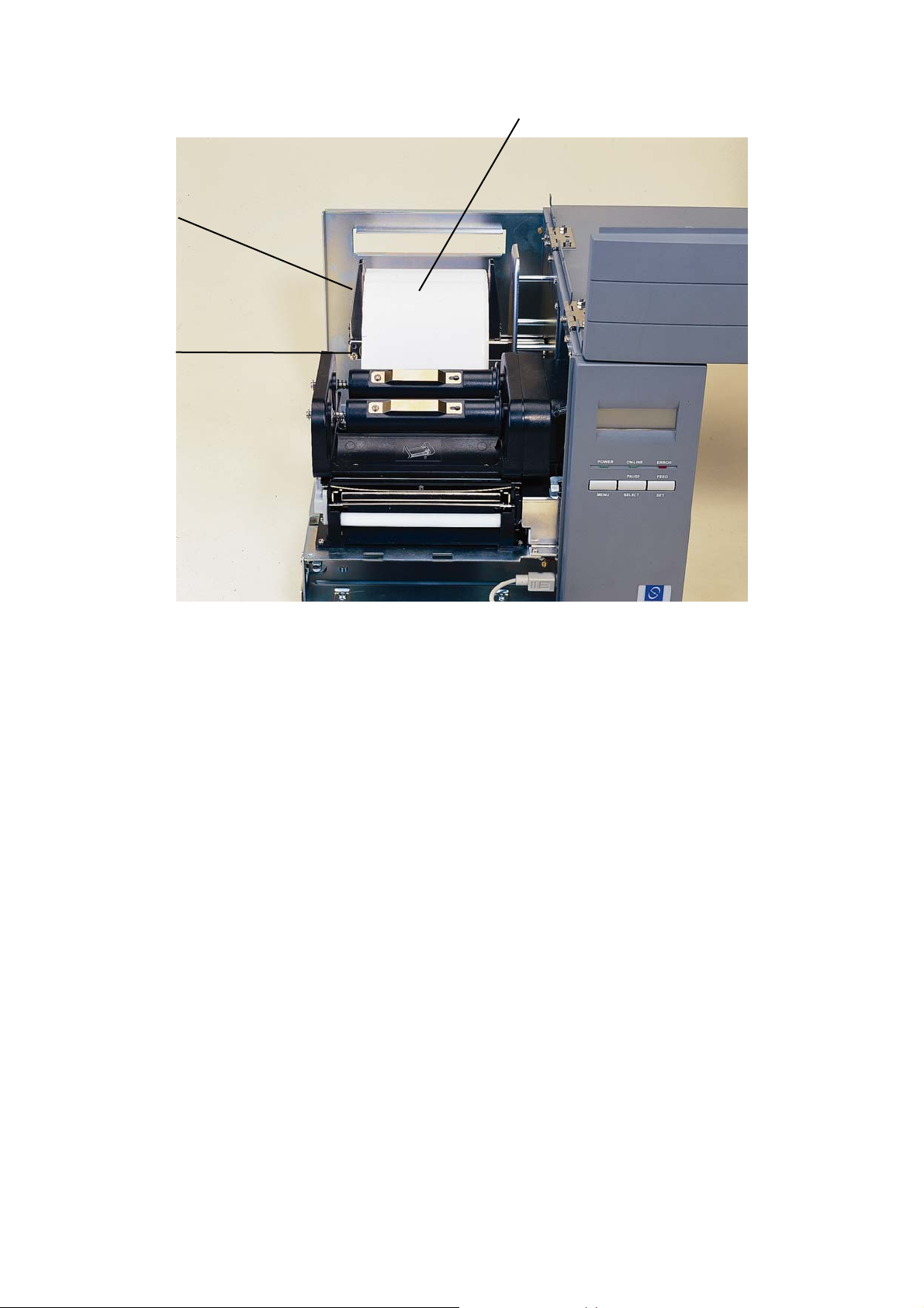
1
2
3
Figure 4. Inserting Label Supply Roll Onto Label Roll Spindle
1. Label Roll
2. Label Roll Guard
3. Label Supply Roll Spindle
10
Page 13
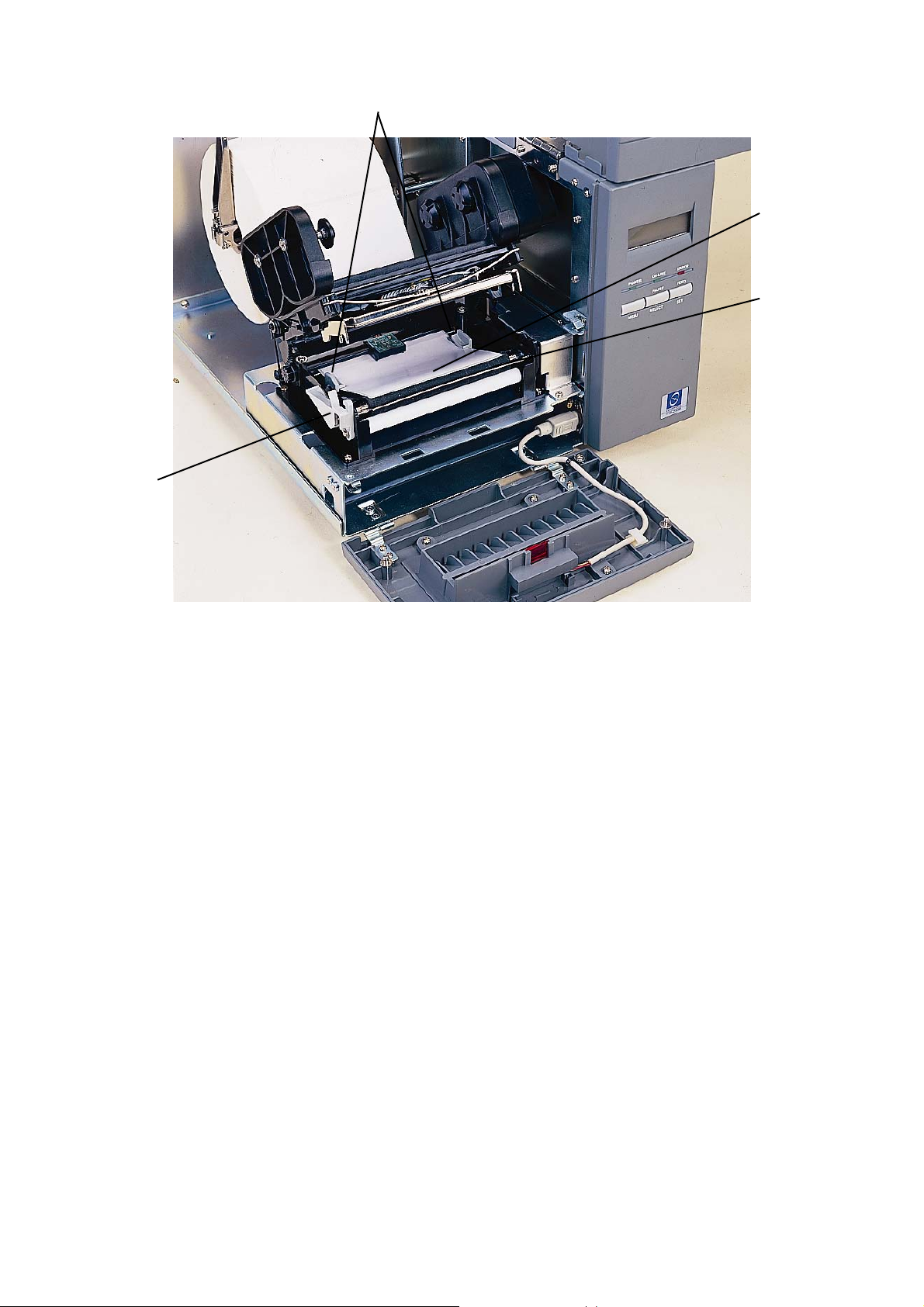
4
1
2
3
Figure 5. Feeding Labels Through Adjustable Label Guide
1. Adjustable Label Guide
2. Label Media
3. Platen
4. Printer Carriage Release Lever
11
Page 14
3.3 Self-Peeling Function
(The self-peeling function and the cutter function cannot be installed at the same
time. To uninstall the cutter, refer to Section 3.4)
To employ the self-peeling function, load the label stock according to the following steps.
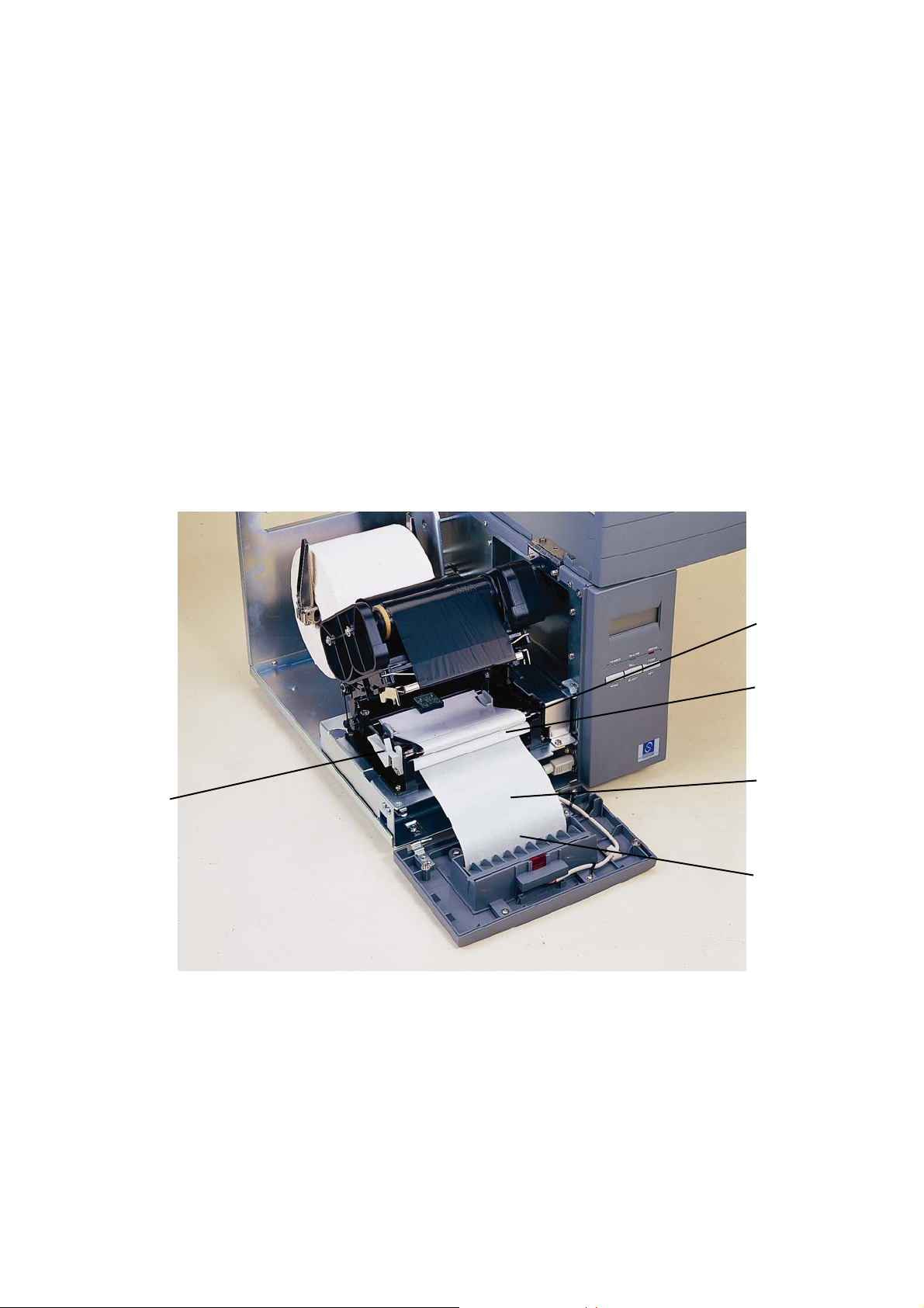
1. Open the printer cover and front panel.
2. Tear off the foremost one or two labels of the label stock, as befits the case.
Feed the backing paper between the platen and the white “self-peeling” roller,
as shown in Figure 6.
3. Feed the backing paper through the backing paper opening in the front panel,
as shown in Figure 7.
4. Close the front panel and printer cover.
5
Figure 6. Setting Up Printer for Self-Peeling Function
1. Platen
2. Self-Peeling Roller
3. Backing Paper
4. Backing Paper Opening
5. Carriage Release Lever
1
2
3
4
12
Page 15
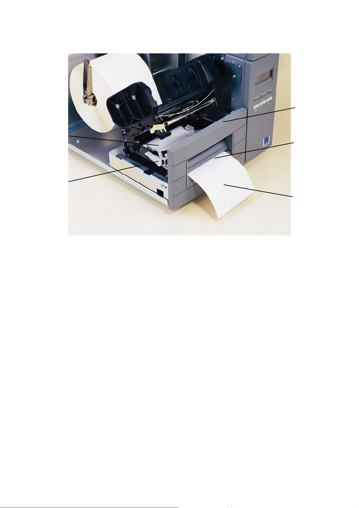
1
5
2
4
3
Figure 7. Printer Ready for Self-Peeling Function
1. Printer Front Panel
2. Backing Paper Opening
3. Backing Paper
4. Printer Carriage Release Lever
5. Label (Media)
13
Page 16
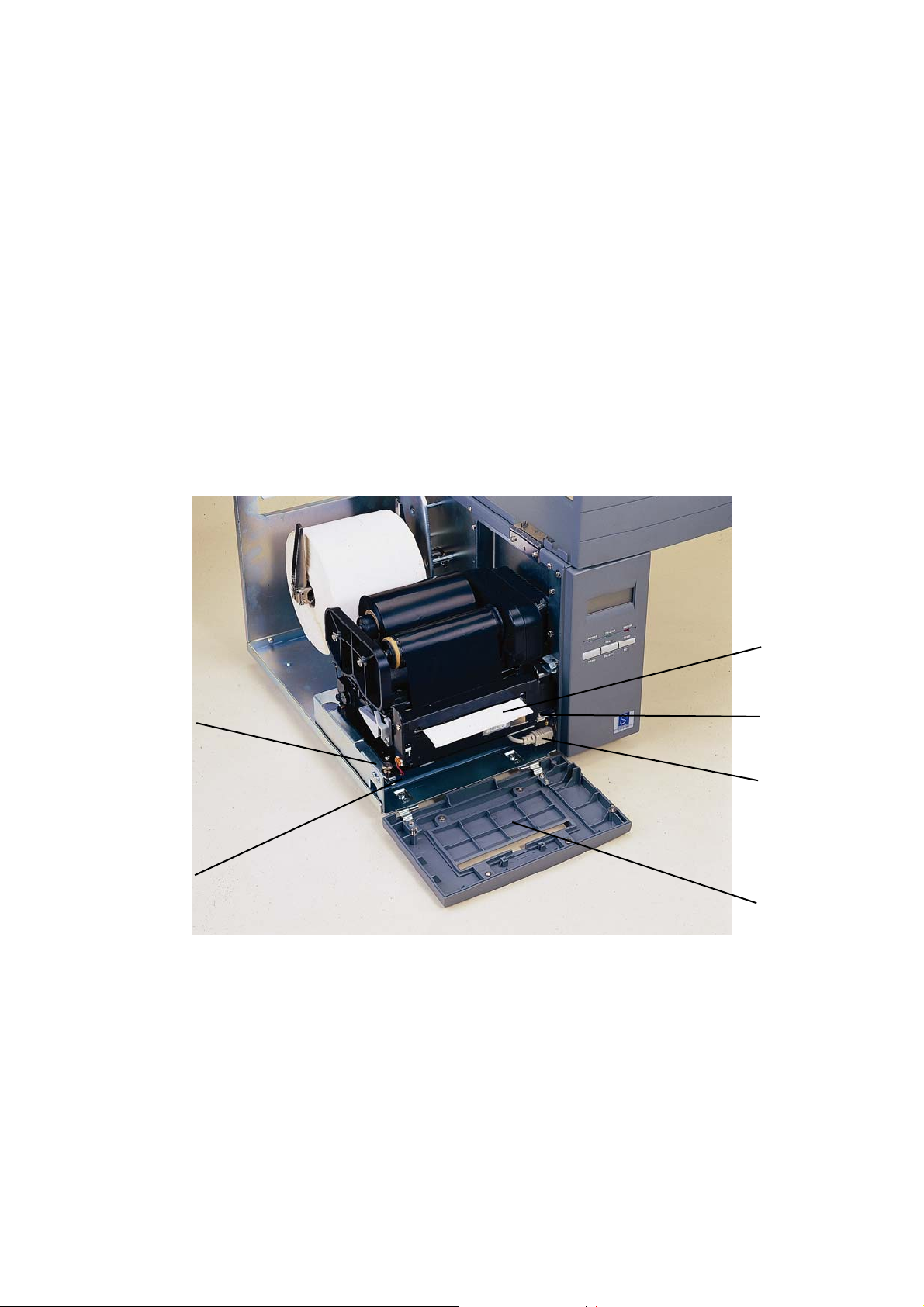
3.4 Cutter Function
(Unlike the aforesaid self-peeling function, the cutter function is not a standard
device of this printer. To have this function, user should additionally purchase the
cutter set, which includes a cutter module and a detachable front panel.)
To employ the cutter function, follow the steps below.
1. Open the printer cover and front panel.
2. Unfasten the front panel, replace it with the one that goes with the cutter
module.
3. Install the cutter module. First fit the cutter module in the slits at the front edge
of the carriage and slide the module to the right. After that, fix the cutter
module in place with the provided tap screw; and then connect the cutter to
the power connector below and to the right of the carriage.
4. Install the ribbon and feed the labels as shown.
5. Put back the front panel and top cover.
6
5
Figure 8 Cutter Function Installation
1. Label
2. Cutter Module
3. Cutter Power Connector
4. Cutter Mode Front Panel
1
2
3
4
5. Cutter Power Cord (Insert the cord in cord clips right under the carriage)
6. Screw
14
Page 17

3.5 Ribbon Loading Instructions
1. Place an empty paper core on the ribbon rewind spindle.
2. Install the ribbon on the ribbon supply spindle.
3. Disengage the printer carriage.
4. Pull the ribbon leader to the front from beneath the printer carriage. Attach the
ribbon leader to the ribbon rewind paper core (with a tape).
5. Rotate the ribbon rewind roller until the ribbon leader is thoroughly, firmly
encompassed by the black section of the ribbon.
6. Engage the printer carriage.
7. Close the printer cover and press the FEED button until the green ON-LINE
LED illuminates.
15
Page 18
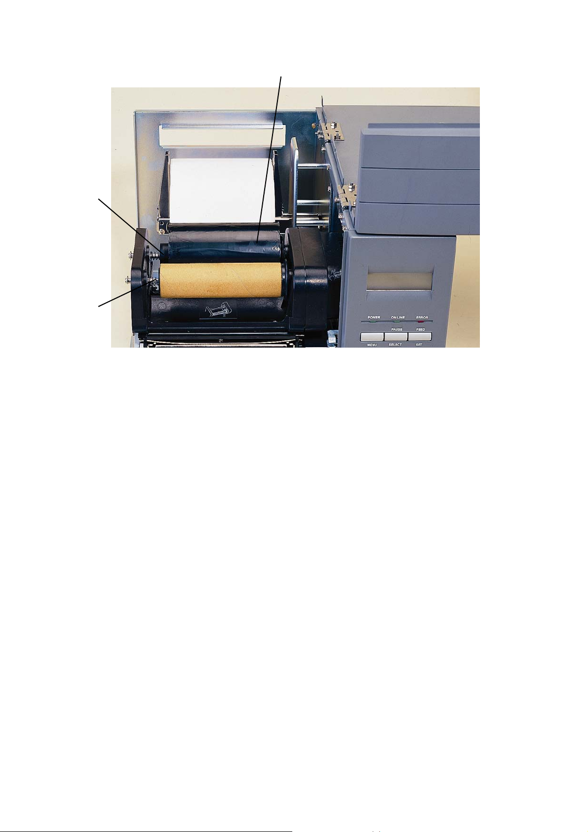
1
2
3
Figure 9. Placement of Ribbon Supply Roll
1. Thermal Transfer Ribbon
2. Ribbon Supply Spindle
3. Ribbon Rewind Spindle
16
Page 19
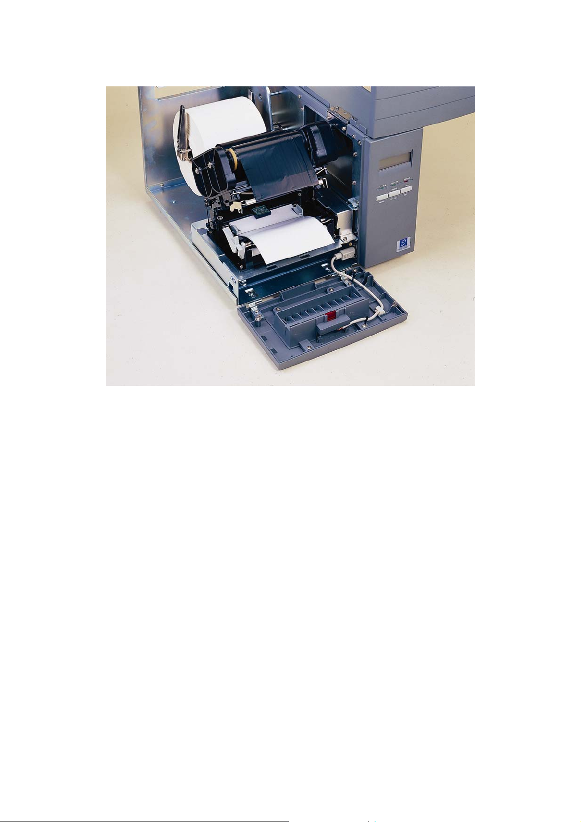
Figure 10. Installation of Label Stock and Thermal Transfer Ribbon
17
Page 20

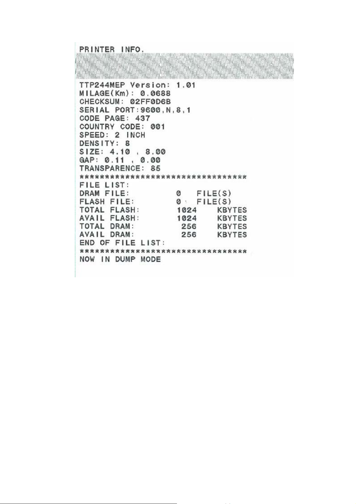
3.6 Self Test
To initiate the self test mode, hold down the FEED button and activate the printer
power simultaneouly. The printer will calibrate the label length. If the label gap is
not detected within 7", the printer stops feeding labels and the media is regarded
as continuous paper. In self test, a check pattern is used to check the performance of the thermal print head. Following the check pattern, the printer prints its
internal settings as listed below:
1. Printer model and firmware version
2. Mileage
3. Flash times
4. Check sum
5. Serial port setting
6. Code page setting
7. Country code setting
8. Print speed setting
9. Print density setting
10. Label size setting
11. Gap (Bline) width and offset setting
12. Backing paper transparence
13. File list
14. Memory available
When the self test is completed, the printer enters the dump mode. Please turn
the printer's power off and then on again to resume normal printing.
18
Page 21
Note:
The physical flash memory and DRAM on board is 2MB respectively. Due to
system firmware will occupy 1MB, so total available flash memory space
for downloads is 1024 K bytes.
For DRAM, system and image buffer will occupy 1792 K bytes, so total
available DRAM for downloads will be 256 K bytes.
19
Page 22
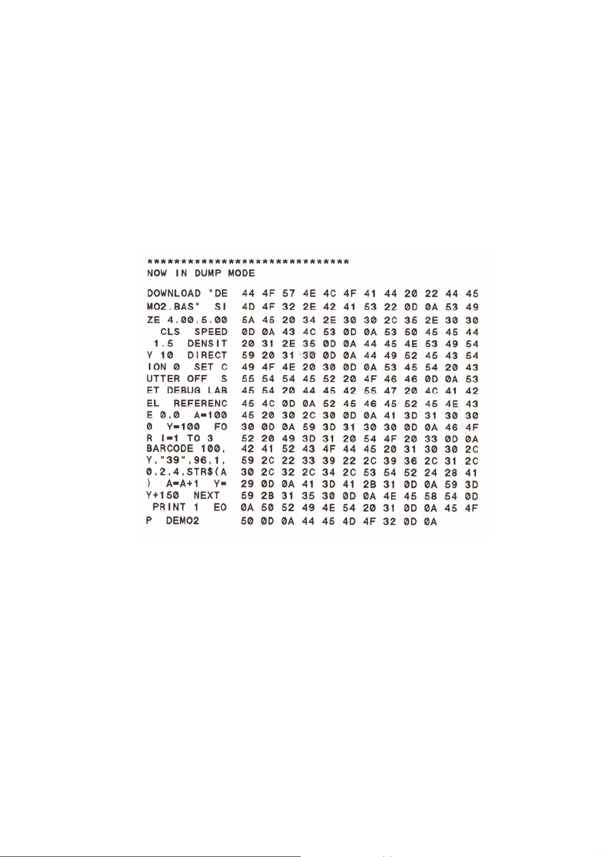
3.7 Dump Mode
After the self test, the printer enters the dump mode. In this mode, any characters sent from the host computer will be printed in two columns, as shown. The
characters received will be shown in the first column, and their corresponding
hexadecimal values, in the second. This is often helpful to users for the verification of programming commands or debugging of printer programs. Reset the
printer by turning the POWER switch off and on.
20
Page 23

4. USING THE PRINTER
4.1 Power-on Utilities
There are three power-on utilities to set up and test the printer hardware. These
utilities are activated by pressing the FEED or PAUSE button and turning on the
printer power simultaneously. The utilities are listed below:
1. Self test
2. Gap sensor calibration
3. Printer initialization
4.1.1 Self Test Utility
Install the label first. Press the FEED button and then turn on the printer power.
Do not release the FEED button until the printer feeds labels. The printer performs the following:
1. Calibrate label pitch
2. Print out thermal print head check pattern
3. Print the internal settings
4. Enter dump mode
For more information on self test and dump mode, refer to Section 3.6, Self Test,
and Section 3.7, Dump Mode.
4.1.2 Gap Sensor Calibration Utility
This utility is used to calibrate the sensitivity of the gap sensor. Users may have
to calibrate the gap sensor on two occasions:
1. Changing to a new type of label media.
2. Initializing the printer.
Note: The ERROR LED may flash if gap sensor is not calibrated properly.
Please follow the steps below to calibrate the gap sensor:
1. Turn off the printer power and install blank labels (without any logo or
character) on the printer.
2. Hold down the PAUSE button and turn on the printer power.
3. Release PAUSE button when the printer feeds labels. Do not turn off the
printer power until the printer stops and the two green LEDs light on.
Note: Black mark sensor has fixed sensitivity. It is no need to calibrate the
black mark sensor
21
Page 24

4.1.3 Printer Initialization
Printer initialization clears all downloaded files resident in the flash memory and
sets printer parameters to default values.
Parameter Default Value
MILEAGE Automatic
FLASH TIMES Automatic
CHECK SUM Automatic
SERIAL PORT 96,N,8,1
CODE PAGE 437 (8 bit), USA (7 bit)
COUNTRY CODE 001
SPEED 2.0”/sec (1.5"/sec, 342M)
DENSITY 8
SIZE 4"x2.5"
GAP(BLINE) 3 mm
TRANSPARANCY Will be reset. Need to re-
calibrate the gap sensor
LCD Language English
Please follow the steps below to initialize the printer:
1. Turn off the printer power.
2. Hold down the PAUSE and FEED buttons and turn on the printer power.
3. Do not release the buttons until the three LEDs flash in turn.
Note:
Printing method (thermal transfer or thermal direct printing ) will be set
automatically at the activation of printer power.
Download files will be deleted after printer initialization.
Sensor calibration is required after printer initialization before printing
labels.
22
Page 25

4.2 Troubleshooting Guide
The following guide lists some of the most common problems that may be
encountered when operating the bar code printer. If the printer still does not
function after all suggested solutions have been invoked, please contact the
Customer Service Department of your purchased reseller or distributor for
assistance
Problem Solution
Ribbon does not advance or rewind The media and ribbon must be
installed and close print head
mechanism prior to turning on printer
power.
Poor print quality Clean the thermal print head.
Adjust the print density setting.
Ribbon and media are not compatible.
Media thickness is over spec.
Power indicator does not illuminate
ON-LINE indicator is off, ERROR
indicator is on
Continuous feeding when printing
labels
Check the power cord, see whether it
is properly connected.
Out of paper or out of ribbon
Calibrate the sensitivity of gap sensor.
Rewind ribbon paper core is not
installed.
Calibrate the gap sensor.
23
Page 26

24
Page 27
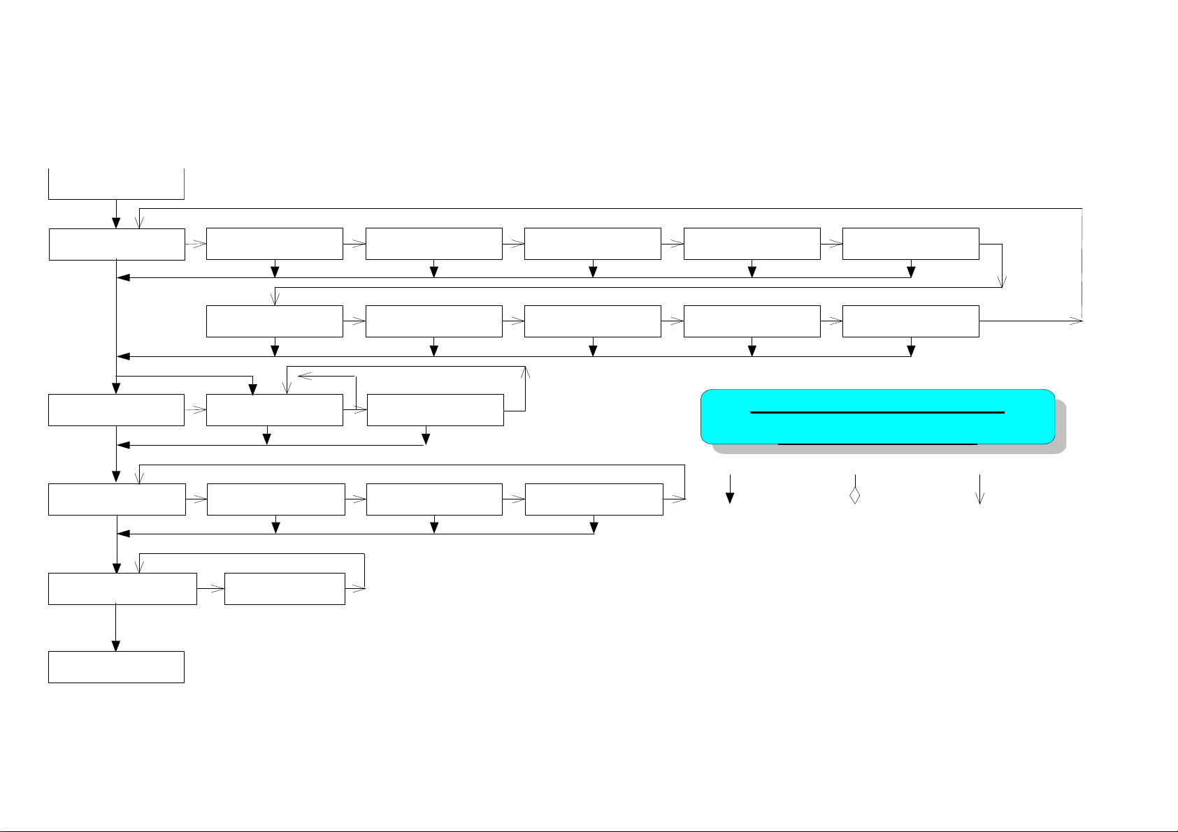
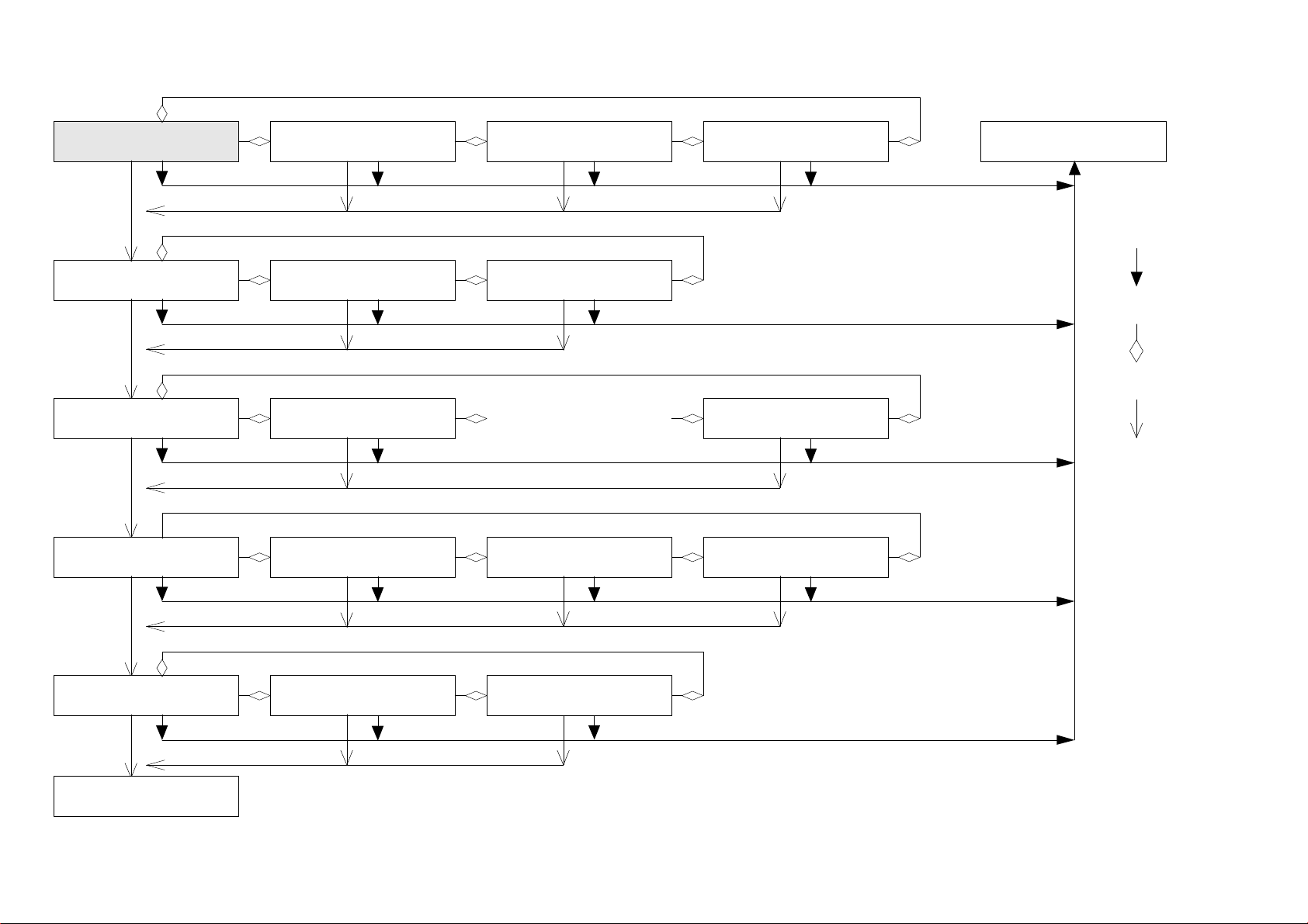
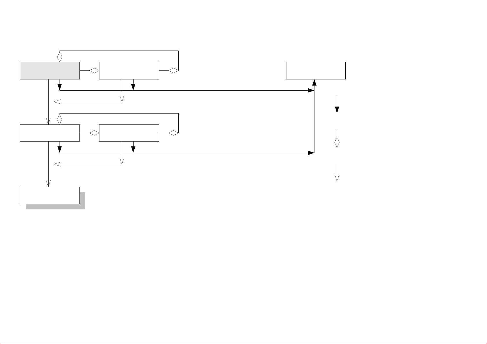
Appendix A Menu Control Flowchart
The following shows the control flowchart of the menu.
READY
PRINTER INFO.:
TTP243M V1.XX
FILE LIST:
END OF LIST
MEMORY INFO.:
F-TOTAL: XXXX K
DATE/TIME:
DATE:XXXX/XX/XX
PRINTER INFO.:
SPEED:3
PRINTER INFO.:
SIZE:X.XX,X.XX
FILE LIST:
XXXXXXXX.XXX
MEMORY INFO.:
F-AVAIL: XXXX K
DATE/TIME:
TIME:XX:XX
PRINTER INFO.:
DENSITY:8
PRINTER INFO.:
GAP:X.XX,X.XX
FILE LIST:
END OF LIST
MEMORY INFO.:
D-TOTAL: XXXX K
PRINTER INFO.:
COM1:96,N,8,1
PRINTER INFO.:
PEEL-OFF:OFF
MEMORY INFO.:
D-AVAIL: XXXX K
PRINTER INFO.:
CODE PAGE:437
PRINTER INFO.:
CUTTER:ON
PANEL CONTROL
FLOW CHART
MENU SELECT SET
PRINTER INFO.:
COUNTRY:001
PRINTER INFO.:
RIBBON:ON
PRINTER SETUP:
LANG:ENG
(Continued on next page)
A-
1
Page 28
PRINTER SETUP:
LANG:ENG
PRINTER SETUP:
SPEED:1.5
PRINTER SETUP:
DENSITY:0
PRINTER SETUP:
BAUD RATE:19200
PRINTER SETUP:
LANG:
PRINTER SETUP:
SPEED:2
PRINTER SETUP:
DENSITY:1
PRINTER SETUP:
BAUD RATE:9600
繁體中文
PRINTER SETUP:
LANG:
PRINTER SETUP:
SPEED:3
日本語
......
PRINTER SETUP:
BAUD RATE:4800
PRINTER SETUP:
LANG:
PRINTER SETUP:
DENSITY:15
PRINTER SETUP:
BAUD RATE:2400
簡体中文
READY
MENU
SELECT
SET
PRINTER SETUP:
PARITY:NONE
PRINTER SETUP:
DATA BITS:8
PRINTER SETUP:
PARITY:EVEN
PRINTER SETUP:
PARITY:ODD
(Continued on next page)
A-
2
Page 29
PRINTER SETUP:
DATA BITS:8
PRINTER SETUP:
STOP BITS:1
PRINTER SETUP:
LANG:ENG
PRINTER SETUP:
DATA BITS:7
PRINTER SETUP:
STOP BITS:2
READY
MENU
SELECT
SET
A-
3
Page 30

TSC Auto ID Technology Co., Ltd.
Headquarters / Factory
No. 35, Sec. 2, Ligong 1st Rd., Wujie Town 11F, No. 205, Sec. 3, Beishin Rd., Shindian City,
, I-Lan County 268, Taiwan, R.O.C. Taipei 231, Taiwan, R.O.C.
TEL: +886-3-990-6677
FAX: +886-3-990-5577
Web site: www.tscprinters.com
E-mail: [email protected]
Taipei Office
TEL: +886-2-8913-1308
FAX: +886-2-8913-1808
 Loading...