


Limited One Year Warranty
T&S warrants to the original purchaser (other than for purposes of resale) that such product is free from defects in material and workmanship for a period of one (1) year from the date of purchase. During this one-year warranty period, if the product is found to be defective, T&S shall, at its options, repair and/ or replace it. To obtain warranty service, products must be returned to...
T&S Brass and Bronze Works, Inc.
Attn: Warranty Repair Department
2 Saddleback Cove
Travelers Rest, SC 29690
Shipping, freight, insurance, and other transportation charges of the product to T&S and the return of repaired or replaced product to the purchaser are the responsibility of the purchaser. Repair and/or replacement shall be made within a reasonable time after receipt by T&S of the returned product. This warranty does not cover Items which have received secondary finishing or have been altered or modified after purchase, or for defects caused by physical abuse to or misuse of the product, or shipment of the products.
Any express warranty not provided herein, and any remedy for Breach of Contract which might arise, is hereby excluded and disclaimed. Any implied warranties of merchantability or fitness for a particular purpose are limited to one year in duration. Under no circumstances shall T&S be liable for loss of use or any specialconsequential costs, expenses ordamages.
Some states do not allow limitations on how long and implied warranty lasts or the exclusion or limitation of incidental or consequential damages, so the above limitations or exclusions may not apply to you. Specific rights under this warranty and other rights vary from state to state.
P/N: 098-006106-45 Rev.2
Date: 980724
Drawn: CW
Checked: MAB 9-8-98
Approved: MW 9-3-98
Installation and
Maintenance
Instructions
B-0873, B-0874, B-1873, B-1874 and B-2973
CENTERSET LAVATORY FAUCETS (with or without Pop-Up)
Deutsch: Installationsund Wartungsanleitungen
Español: la Instalación y las Instrucciones de Mantenimiento
Français: les Instructions d’Installation et d’Entretien

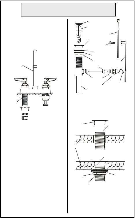
Exploded View
23
16
15
22
12 14
11
8
7
6
10
5
9
1
2
3
4
21
12 |
|
11 |
20 |
|
|
17 |
19 |
|
15 |
18
13
1
* Some items are listed for instructional purposes and may not be sold as separate parts.

Part Number Guide
Base Faucet Assemblies
1 |
Body Faucet for Pop-up |
B-0873 |
* |
|
Body Faucet w/o Pop-up |
B-0874 |
* |
2 |
Washer, Rosette |
|
001000-45 |
3 |
Locknut |
|
002954-45 |
4 |
Nut, Nipple Coupling |
|
000958-20 |
5 |
Asm, Metering Valve - Hot |
002879-40 |
|
|
Asm, Metering Valve - Cold |
002880-40 |
|
6 |
Insulator, Cap |
|
000535-20 |
7 |
Set Screw |
|
000938-45 |
8 |
Cap - Cold |
|
000628-40 |
|
Cap - Hot |
|
000627-40 |
9 |
Asm, Eterna Spindle - LH |
|
005959-40 |
|
Asm, Eterna Spindle - RH |
|
005960-40 |
10 |
Handle, Lever - Cold |
001636-45 |
|
|
Handle, Lever - Hot |
|
001637-45 |
11 |
Index Button, Blue - Cold |
001660-45 |
|
|
Index Button, Red - Hot |
001661-45 |
|
12 |
Screw, Lever Handle |
000922-45 |
|
13 |
Asm, Meter Valve - Hot |
|
002879-40 |
|
Asm, Meter Valve - Cold |
|
002880-40 |
14 |
Handle, Alpine Lexan |
001144-45 |
|
15 |
Screw, Lever Handle |
000925-45 |
|
16 |
Index, Button - Blue, Cold |
001327-40 |
|
|
Index, Button - Red, Hot |
001328-40 |
|
17 |
Handle, Lavatory - 3 Wing - Cold |
001784-40 |
|
|
Handle, Lavatory - 3 Wing - Hot |
001783-40 |
|
18 |
Asm, Eterna Spindle - Cold |
006009-40 |
|
|
Asm, Eterna Spindle - Hot |
006010-40 |
|
19 |
Handle, Wrist Action 4" Cold |
B-WH4C |
|
|
Handle, Wrist Action 4" Hot |
B-WH4H |
|
20 |
Index, Snapin - Red, Hot |
* |
|
|
Index, Snapin - Blue, Cold |
* |
|
21 |
Asm, Drain Pop-up |
|
B-0898 |
|
|
|
|
Nozzle Assemblies
22 |
Nozzle, Gooseneck |
BL-5570-01 |
005028-40 |
|
|
Nozzle, Gooseneck |
B-0892 |
000393-40 |
|
23 |
Aerator |
3/8-18 Male Thread |
B-0199-02 |
|
|
Aerator |
55/64-27 Female Thread |
B-0199-01 |
|
|
|
|
|
|
General Instructions
Nozzle Installation: B-0873
Note: Nozzle should be installed first.
1. Apply teflon tape or pipe joint compound to threaded end of no.22. Screw no.22 into no.1, rotate no.22 to face front of sink.
22
1 


sink
shank


 2
2 
 3
3

 4
4
Faucet Installation: B-0873
2.Shut off water supply and drain lines. Drill (2) two holes into sink or countertop.
3.Remove no.4, 3, and 2 from no.1 shank, then install no.1 thru holes in sink, replace no.2, 3, and 4. Tighten no.3 with a wrench.
4.Connect water supply lines and check for leaks.
Installation: (Pop-Up Valve)
1.Remove pop-up drain stopper, with ‘o’-ring and flange from pop-up assembly.
2.Remove rod clip, lift rod, rod guide nut, rubber washer androd ball assembly from drain body.
‘o’-ring |
|
pop-up drain |
|
stopper |
|
stem |
|
flange |
|
screw |
|
rubber washer |
|
washer |
|
locknut |
lift rod |
ball rod |
|
gasket |
|
nut |
rod clip |
drain body |
|
3. Insert drain body from bottom of sink drain hole, reassemble flange to drain body, tightening as far possible.
flange |
drain pipe |
|
|
||
|
drain body |
|
sink base |
|
|
|
flange flush with |
|
|
sink bottom |
|
washer |
rubber |
|
washer |
||
|
||
locknut |
|
4. Slide rubber washer on drain pipe up against bottom of sink. Tighten washer and locknut firmly against base for a tight seal.
 Loading...