

Page 1
Installation and
Maintenance
Limited One Year Warranty
T&S warrants to the original purchaser
(other than for purposes of resale) that such
product is free from defects in material and
workmanship for a period of one (1) year
from the date of purchase. During this oneyear warranty period, if the product is found
to be defec ve, T&S shall, at its op ons,
repair and/or replace it. To obtain warranty
service, products must be returned to...
T&S Brass and Bronze Works, Inc.
AƩ n: Warranty Repair Department
2 Saddleback Cove
Travelers Rest, SC 29690
Shipping, freight, insurance, and other
transportation charges of the product
to T&S and the return of repaired or
replaced product to the purchaser are the
responsibility of the purchaser. Repair
and/or replacement shall be made within a
reasonable me a er receipt by T&S of the
returned product. This warranty does not
cover Items which have received secondary
fi nishing or have been altered or modifi ed
a er purchase, or for defects caused by
physical abuse to or misuse of the product,
or shipment of the products.
Any express warranty not provided
herein, and any remedy for Breach of
Contract which might arise, is hereby
excluded and disclaimed. Any implied
warran es of merchantability or fi tness for
a par cular purpose are limited to one year
in dura on. Under no circumstances shall
T&S be liable for loss of use or any special
consequen al costs, expenses or damages.
Some states do not allow limitations
on how long and implied warranty lasts
or the exclusion or limita on of incidental
or consequen al damages, so the above
limita ons or exclusions may not apply to
you. Specifi c rights under this warranty and
other rights vary from state to state.
Instructions
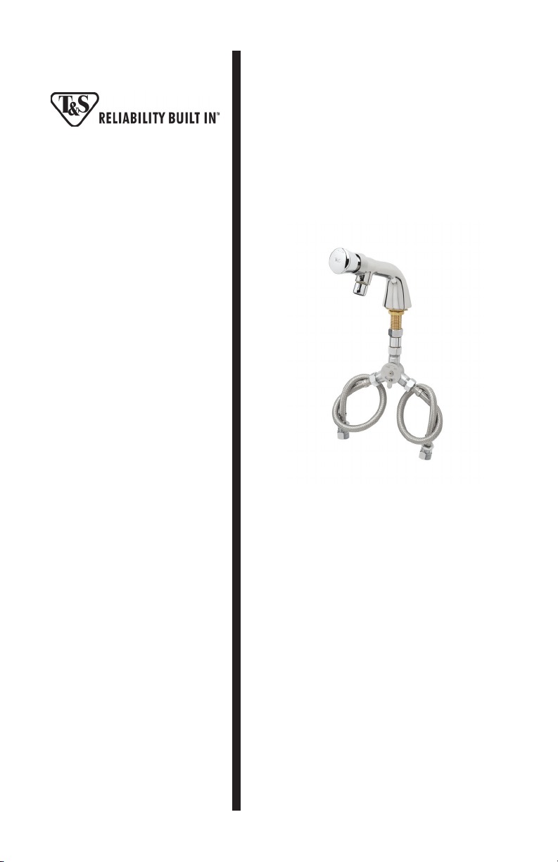
B-0805 SERIES
METERING FAUCETS
Deutsch: InstallaƟ ons- und
Wartungsanleitungen
Español: la Instalación y las
Instrucciones de
Mantenimiento
P/N: 098-003151-45 Rev.5
Date: 03-11-15
Drawn: TEH
Checked: JRM 03-30-15
Approved: JHB 03-31-15
Français: les InstrucƟ ons
d’InstallaƟ on et
d’EntreƟ en
Page 2
11
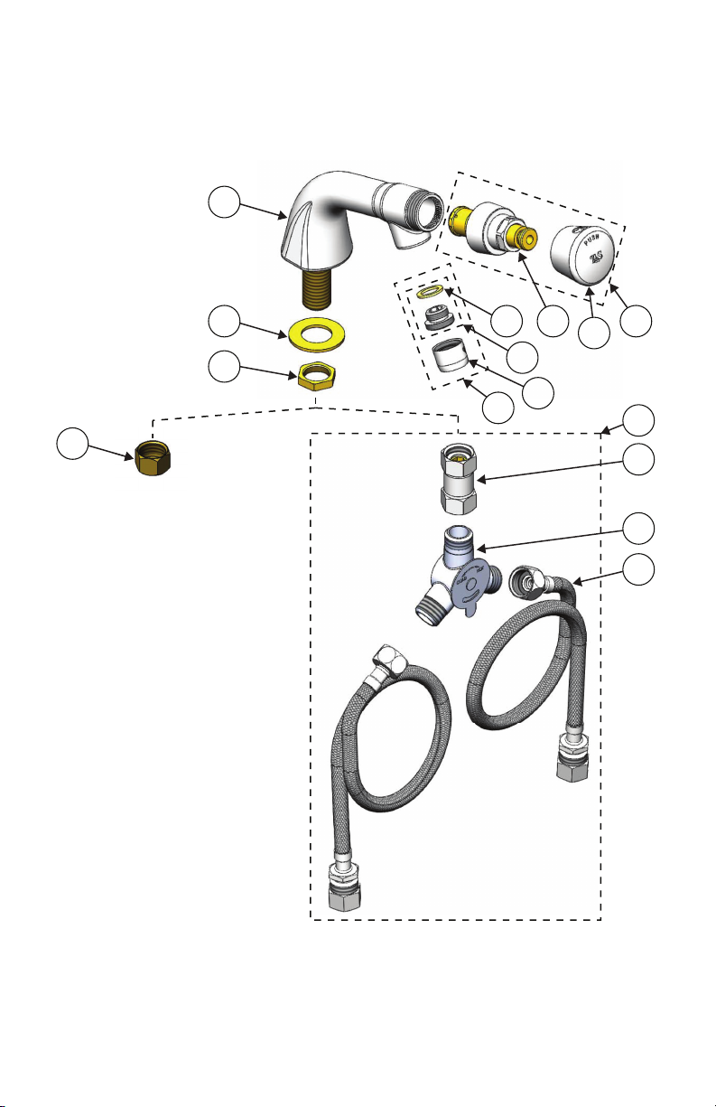
Exploded View
8
9
10
4
7
3
6
5
1
2
12
13
B-0805/B-0806
Series
14
15
B-0807/B-0808
Series
2
Page 3

Part Number Guide
Metering Faucet Assembly
1 Asm, Push Bu on Metering Cartridge & Cap 238AB
2 Asm, Push Bu on Cap - Blank 014193-40
3 Push Bu on Metering Cartridge 238A
4 Aerator, 2.2 GPM, Adapter & Washer B-0199-02
5 Aerator, 2.2 GPM B-0199-01
6 Adapter, 3/8” to Aerator 044A
7 Washer 001043-45
8 Body, Faucet N/A
9 Washer, Brass Lock 000999-45
10 Locknut, Shank 002954-45
11 Nut, Nipple Coupling (B-0805/B-0806 Series) 000958-20
Parts Applicable to the B-0807/B-0808 Series Only
12 Asm, Mixing Valve with Flexible 1/2” Male Inlets 019321-40
13 Coupling, 1/2” NPSM Swivel Coupling 017506-45
14 Mechanical Mixing Valve 5EF-0006
15 Hoses, Flexible Connector (Qty 2) 019192-45
3
Page 4

General Instructions
InstallaƟ on: B-0805/B-0806 Series
1. Turn off water supply and drain lines. Flush lines thoroughly of debris.
2. Drill a 1” diameter hole through sink or countertop in desired loca on.
3. Remove no.11, no.10 and no.9 from no.8. Place no.8 through opening in sink.
4. Replace no.9, no.10 and no.11 onto no.8 and ghten against bo om of sink.
Hold no.8 fl at against sink while ghtening no.10.
5. Connect water supply to no.11 and check for leaks.
Note: Flow is adjustable from instantaneous shut-off to extended fl ow by
external adjustment:
Note: Each metering cartridge is preset for approximately 10 seconds at the
factory. They may be reset at installaƟ on. If water pressure varies, the cycle Ɵ me
will also vary.
Note: See installa on instruc on 098-014733-45 for cartridge adjustment.
InstallaƟ on: B-0807/B-0808 Series
1. Turn off water supply and drain lines. Flush lines
thoroughly of debris.
2. Drill a 1” diameter hole through sink or
countertop in desired loca on.
3. Remove no.10 and no.9 from no.8. Place no.8
through opening in sink.
4. Replace no.9 and no.10 onto no.8 and ghten
against bo om of sink. Hold no.8 fl at against sink
while ghtening no.10.
5. Place no.13 on no.8 and ghten.
6. Place no.14 on no.13 and ghten.
7. Place both no.15’s on each side of no.14 and
ghten.
8. Connect water supply to no.15’s and check for
leaks.
4
8
9
10
13
14
15
Page 5

Instrucciones Generales
Instalación: B-0805/B-0806 la Serie
1. Desconecte el suministro de agua y drene las tuberías. Limpie bien la suciedad
de las tuberías.
2. Haga un agujero de 25 mm con un taladro en la pila o en la encimera en la
ubicación deseada.
3. Separe el no. 11, el no. 10 y el no. 9 del no. 8. Coloque el no. 8 a través del
agujero de la pila.
4. Vuelva a colocar en su si o el no. 9, el no. 10 y el no. 11 en el no. 8 y ajuste
contra la parte inferior de la pila. Sostenga el no. 8 en plano contra la pila
mientras ajusta el no. 10.
5. Conecte el suministro de agua al no. 11 y busque posibles fugas.
Nota: El fl ujo se puede ajustar de automá co a ampliado mediante un ajuste
externo:
Nota: La válvula de medición viene ajustada de fábrica con una duración de 10
segundos. Se puede volver a confi gurar durante la instalación. Si varía la presión
del agua, la duración del ciclo también variará.
Nota: Consulte las instrucciones de instalación 098-014733-45 para ajustar la
válvula.
Instalación: B-0807/B-0808 la Serie
1. Desconecte el suministro de agua y drene las
tuberías. Limpie bien la suciedad de las tuberías.
2. Haga un agujero de 25 mm con un taladro en la pila
o en la encimera en la ubicación deseada.
3. Separe el no. 10 y el no. 9 del no. 8. Coloque el no.
8 a través del agujero de la pila.
4. Vuelva a colocar el no. 9 y el no. 10 en el no. 8 y
ajuste contra la parte inferior de la pila. Sostenga el
no. 8 en plano contra la pila mientras ajusta el no. 10.
5. Coloque el no. 13 en el no. 8 y ajuste.
6. Coloque el no. 14 en el no. 13 y ajuste.
7. Coloque los dos no. 15 en cada lado del no. 14 y
ajuste.
8. Conecte el suministro de agua al no. 15 y busque
posibles fugas.
5
8
9
10
13
14
15
Page 6

Instructions Générales
InstallaƟ on: B-0805/B-0806 Série
1. Couper l’arrivée d’eau et vider les tuyaux. Ne oyer les canalisa ons.
2. Percer un trou de 2,5 cm de diamètre dans l’évier ou sur le plan de travail à
l’endroit souhaité.
3. Re rer le N° 11, le N° 10 et le N° 9 du N° 8. Placer le N° 8 dans l’ouverture de
l’évier.
4. Replacer le N° 9, le N° 10 et le N° 11 sur le N° 8 et serrer en bas de l’évier.
Tenir le N° 8 à plat contre l’évier tout en serrant le N° 10.
5. Connecter l’arrivée d’eau au N° 11 et vérifi er les fuites éventuelles.
Remarque : un réglage externe vous permet d’ajuster le fl ux (arrêt total
jusqu’à fl ux maximum).
Remarque : chaque cartouche de mesure est préconfi gurée pendant environ 10
secondes à l’usine. Elles peuvent être reconfi gurées lors de l’installaƟ on. Si la
pression de l’eau varie, la durée du cycle sera également modifi ée.
Note : consulter les instruc ons d’installa on 098-014733-45 pour le réglage
de la cartouche.
InstallaƟ on: B-0807/B-0808 Série
1. Couper l’arrivée d’eau et vider les tuyaux.
Ne oyer les canalisa ons.
2. Percer un trou de 2,5 cm de diamètre dans l’évier
ou sur le plan de travail à l’endroit souhaité.
3. Re rer le N° 10 et le N° 9 du N° 8. Placer le N° 8
dans l’ouverture de l’évier.
4. Replacer le N° 9 et le N° 10 sur le N° 8 et serrer en
bas de l’évier. Tenir le N° 8 à plat contre l’évier tout en
serrant le N° 10.
5. Placer le N° 13 sur le N° 8 et serrer.
6. Placer le N° 14 sur le N° 13 et serrer.
7. Placer les deux N° 15 de chaque côté du N° 14 et
serrer.
8. Connecter l’arrivée d’eau aux deux N° 15 et vérifi er
les fuites éventuelles.
6
8
9
10
13
14
15
Page 7

Allgemeine Anleitungen
InstallaƟ on: B-0805/B-0806 Serie
1. Wasserzufuhr ausschalten und Rohre entleeren. Alle Rückstände aus den Rohren
spülen.
2. An der gewünschten Stelle eine Öff nung mit einem Durchmesser von 2,5 cm im
Spülbecken oder in der Arbeitsfl äche anbringen.
3. Nr. 11, Nr. 10 und Nr. 9 von Nr. 8 abnehmen. Nr.8 durch die Öff nung im Spülbecken
einbringen.
4. Nr. 9, Nr. 10 und Nr. 11 wieder an Nr. 8 anbringen und unten am Spülbecken befes gen.
Nr. 8 gegen das Spülbecken drücken und Nr. 10 festziehen.
5. Wasserzufuhr wieder an Nr. 11 anschließen und auf undichte Stellen prüfen.
Hinweis: Der Durchfl uss kann extern von einer Sofortsperre bis auf hohe
Strömungswerte eingestellt werden:
Hinweis: Jede Dosierpatrone ist ab Werk auf ca. 10 Sekunden voreingestellt. Diese
Einstellung kann beim Einbau geändert werden. Bei schwankendem Wasserdruck ändert
sich auch die Zukluszeit.
Hinweis: Informa onen zur Einstellung der Patrone fi nden Sie in Installa onsanleitung
098-014733-45.
InstallaƟ on: B-0807/B-0808 Serie
1. Wasserzufuhr ausschalten und Rohre entleeren.
Alle Rückstände aus den Rohren spülen.
2. An der gewünschten Stelle eine Öff nung mit einem
Durchmesser von 2,5 cm im Spülbecken oder in der
Arbeitsfl äche anbringen.
3. Nr. 10 und Nr. 9 von Nr. 8 abnehmen. Nr. 8 durch die
Öff nung im Spülbecken einbringen.
4. Nr. 9 und Nr. 10 wieder an Nr. 8 anbringen und unten
am Spülbecken befes gen. Nr. 8 gegen das Spülbecken
drücken und Nr. 10 festziehen.
5. Nr. 13 auf Nr. 8 platzieren und festziehen.
6. Nr. 14 auf Nr. 13 platzieren und festziehen.
7. Nr. 15 auf jede Seite von mit Nr. 14 gekennzeichneten
Komponenten platzieren und festziehen.
8. Wasserzufuhr wieder an alle mit Nr. 15
gekennzeichneten Komponenten anschließen und auf
undichte Stellen prüfen.
7
8
9
10
13
14
15
Page 8

RELATED T&S BRASS PRODUCT LINE
EC-3100
ChekPoint Electronic Faucet
Deck-Mount, Gooseneck, AD/DC Control Module
T&S BRASS AND BRONZE WORKS, INC.
A fi rm commitment to application-engineered plumbing products
Travelers Rest, SC 29690 ‘De Veenhoeve’
Phone: (864) 834-4102 Oude Nieuwveenseweg 84
Fax: (864) 834-3518 2441 CW Nieuwveen
E-mail:
2 Saddleback Cove, P.O. Box 1088, T & S Brass-Europe
tsbrass@tsbrass.com The Netherlands
 Loading...